WO2010013613A1 - エアクリーナ、及びエンジン制御システム - Google Patents
エアクリーナ、及びエンジン制御システム Download PDFInfo
- Publication number
- WO2010013613A1 WO2010013613A1 PCT/JP2009/063017 JP2009063017W WO2010013613A1 WO 2010013613 A1 WO2010013613 A1 WO 2010013613A1 JP 2009063017 W JP2009063017 W JP 2009063017W WO 2010013613 A1 WO2010013613 A1 WO 2010013613A1
- Authority
- WO
- WIPO (PCT)
- Prior art keywords
- air
- air cleaner
- cylinder filter
- flow rate
- egr valve
- Prior art date
- Legal status (The legal status is an assumption and is not a legal conclusion. Google has not performed a legal analysis and makes no representation as to the accuracy of the status listed.)
- Ceased
Links
Images




Classifications
-
- F—MECHANICAL ENGINEERING; LIGHTING; HEATING; WEAPONS; BLASTING
- F02—COMBUSTION ENGINES; HOT-GAS OR COMBUSTION-PRODUCT ENGINE PLANTS
- F02M—SUPPLYING COMBUSTION ENGINES IN GENERAL WITH COMBUSTIBLE MIXTURES OR CONSTITUENTS THEREOF
- F02M26/00—Engine-pertinent apparatus for adding exhaust gases to combustion-air, main fuel or fuel-air mixture, e.g. by exhaust gas recirculation [EGR] systems
-
- F—MECHANICAL ENGINEERING; LIGHTING; HEATING; WEAPONS; BLASTING
- F02—COMBUSTION ENGINES; HOT-GAS OR COMBUSTION-PRODUCT ENGINE PLANTS
- F02M—SUPPLYING COMBUSTION ENGINES IN GENERAL WITH COMBUSTIBLE MIXTURES OR CONSTITUENTS THEREOF
- F02M35/00—Combustion-air cleaners, air intakes, intake silencers, or induction systems specially adapted for, or arranged on, internal-combustion engines
- F02M35/02—Air cleaners
- F02M35/024—Air cleaners using filters, e.g. moistened
-
- B—PERFORMING OPERATIONS; TRANSPORTING
- B01—PHYSICAL OR CHEMICAL PROCESSES OR APPARATUS IN GENERAL
- B01D—SEPARATION
- B01D46/00—Filters or filtering processes specially modified for separating dispersed particles from gases or vapours
- B01D46/24—Particle separators, e.g. dust precipitators, using rigid hollow filter bodies
- B01D46/2403—Particle separators, e.g. dust precipitators, using rigid hollow filter bodies characterised by the physical shape or structure of the filtering element
- B01D46/2411—Filter cartridges
-
- B—PERFORMING OPERATIONS; TRANSPORTING
- B01—PHYSICAL OR CHEMICAL PROCESSES OR APPARATUS IN GENERAL
- B01D—SEPARATION
- B01D46/00—Filters or filtering processes specially modified for separating dispersed particles from gases or vapours
- B01D46/42—Auxiliary equipment or operation thereof
- B01D46/44—Auxiliary equipment or operation thereof controlling filtration
- B01D46/444—Auxiliary equipment or operation thereof controlling filtration by flow measuring
-
- B—PERFORMING OPERATIONS; TRANSPORTING
- B01—PHYSICAL OR CHEMICAL PROCESSES OR APPARATUS IN GENERAL
- B01D—SEPARATION
- B01D46/00—Filters or filtering processes specially modified for separating dispersed particles from gases or vapours
- B01D46/56—Filters or filtering processes specially modified for separating dispersed particles from gases or vapours with multiple filtering elements, characterised by their mutual disposition
- B01D46/62—Filters or filtering processes specially modified for separating dispersed particles from gases or vapours with multiple filtering elements, characterised by their mutual disposition connected in series
- B01D46/64—Filters or filtering processes specially modified for separating dispersed particles from gases or vapours with multiple filtering elements, characterised by their mutual disposition connected in series arranged concentrically or coaxially
-
- F—MECHANICAL ENGINEERING; LIGHTING; HEATING; WEAPONS; BLASTING
- F02—COMBUSTION ENGINES; HOT-GAS OR COMBUSTION-PRODUCT ENGINE PLANTS
- F02D—CONTROLLING COMBUSTION ENGINES
- F02D21/00—Controlling engines characterised by their being supplied with non-airborne oxygen or other non-fuel gas
- F02D21/06—Controlling engines characterised by their being supplied with non-airborne oxygen or other non-fuel gas peculiar to engines having other non-fuel gas added to combustion air
- F02D21/08—Controlling engines characterised by their being supplied with non-airborne oxygen or other non-fuel gas peculiar to engines having other non-fuel gas added to combustion air the other gas being the exhaust gas of engine
-
- F—MECHANICAL ENGINEERING; LIGHTING; HEATING; WEAPONS; BLASTING
- F02—COMBUSTION ENGINES; HOT-GAS OR COMBUSTION-PRODUCT ENGINE PLANTS
- F02D—CONTROLLING COMBUSTION ENGINES
- F02D35/00—Controlling engines, dependent on conditions exterior or interior to engines, not otherwise provided for
-
- F—MECHANICAL ENGINEERING; LIGHTING; HEATING; WEAPONS; BLASTING
- F02—COMBUSTION ENGINES; HOT-GAS OR COMBUSTION-PRODUCT ENGINE PLANTS
- F02D—CONTROLLING COMBUSTION ENGINES
- F02D41/00—Electrical control of supply of combustible mixture or its constituents
- F02D41/02—Circuit arrangements for generating control signals
- F02D41/18—Circuit arrangements for generating control signals by measuring intake air flow
-
- F—MECHANICAL ENGINEERING; LIGHTING; HEATING; WEAPONS; BLASTING
- F02—COMBUSTION ENGINES; HOT-GAS OR COMBUSTION-PRODUCT ENGINE PLANTS
- F02M—SUPPLYING COMBUSTION ENGINES IN GENERAL WITH COMBUSTIBLE MIXTURES OR CONSTITUENTS THEREOF
- F02M35/00—Combustion-air cleaners, air intakes, intake silencers, or induction systems specially adapted for, or arranged on, internal-combustion engines
- F02M35/02—Air cleaners
- F02M35/0201—Housings; Casings; Frame constructions; Lids; Manufacturing or assembling thereof
- F02M35/021—Arrangements of air flow meters in or on air cleaner housings
-
- F—MECHANICAL ENGINEERING; LIGHTING; HEATING; WEAPONS; BLASTING
- F02—COMBUSTION ENGINES; HOT-GAS OR COMBUSTION-PRODUCT ENGINE PLANTS
- F02M—SUPPLYING COMBUSTION ENGINES IN GENERAL WITH COMBUSTIBLE MIXTURES OR CONSTITUENTS THEREOF
- F02M35/00—Combustion-air cleaners, air intakes, intake silencers, or induction systems specially adapted for, or arranged on, internal-combustion engines
- F02M35/10—Air intakes; Induction systems
-
- G—PHYSICS
- G01—MEASURING; TESTING
- G01F—MEASURING VOLUME, VOLUME FLOW, MASS FLOW OR LIQUID LEVEL; METERING BY VOLUME
- G01F1/00—Measuring the volume flow or mass flow of fluid or fluent solid material wherein the fluid passes through a meter in a continuous flow
-
- F—MECHANICAL ENGINEERING; LIGHTING; HEATING; WEAPONS; BLASTING
- F02—COMBUSTION ENGINES; HOT-GAS OR COMBUSTION-PRODUCT ENGINE PLANTS
- F02B—INTERNAL-COMBUSTION PISTON ENGINES; COMBUSTION ENGINES IN GENERAL
- F02B29/00—Engines characterised by provision for charging or scavenging not provided for in groups F02B25/00, F02B27/00 or F02B33/00 - F02B39/00; Details thereof
- F02B29/04—Cooling of air intake supply
- F02B29/0406—Layout of the intake air cooling or coolant circuit
-
- F—MECHANICAL ENGINEERING; LIGHTING; HEATING; WEAPONS; BLASTING
- F02—COMBUSTION ENGINES; HOT-GAS OR COMBUSTION-PRODUCT ENGINE PLANTS
- F02D—CONTROLLING COMBUSTION ENGINES
- F02D41/00—Electrical control of supply of combustible mixture or its constituents
- F02D41/0002—Controlling intake air
- F02D41/0007—Controlling intake air for control of turbo-charged or super-charged engines
-
- F—MECHANICAL ENGINEERING; LIGHTING; HEATING; WEAPONS; BLASTING
- F02—COMBUSTION ENGINES; HOT-GAS OR COMBUSTION-PRODUCT ENGINE PLANTS
- F02D—CONTROLLING COMBUSTION ENGINES
- F02D41/00—Electrical control of supply of combustible mixture or its constituents
- F02D41/0025—Controlling engines characterised by use of non-liquid fuels, pluralities of fuels, or non-fuel substances added to the combustible mixtures
- F02D41/0047—Controlling exhaust gas recirculation [EGR]
- F02D41/005—Controlling exhaust gas recirculation [EGR] according to engine operating conditions
- F02D41/0052—Feedback control of engine parameters, e.g. for control of air/fuel ratio or intake air amount
-
- F—MECHANICAL ENGINEERING; LIGHTING; HEATING; WEAPONS; BLASTING
- F02—COMBUSTION ENGINES; HOT-GAS OR COMBUSTION-PRODUCT ENGINE PLANTS
- F02M—SUPPLYING COMBUSTION ENGINES IN GENERAL WITH COMBUSTIBLE MIXTURES OR CONSTITUENTS THEREOF
- F02M26/00—Engine-pertinent apparatus for adding exhaust gases to combustion-air, main fuel or fuel-air mixture, e.g. by exhaust gas recirculation [EGR] systems
- F02M26/02—EGR systems specially adapted for supercharged engines
- F02M26/04—EGR systems specially adapted for supercharged engines with a single turbocharger
- F02M26/05—High pressure loops, i.e. wherein recirculated exhaust gas is taken out from the exhaust system upstream of the turbine and reintroduced into the intake system downstream of the compressor
-
- F—MECHANICAL ENGINEERING; LIGHTING; HEATING; WEAPONS; BLASTING
- F02—COMBUSTION ENGINES; HOT-GAS OR COMBUSTION-PRODUCT ENGINE PLANTS
- F02M—SUPPLYING COMBUSTION ENGINES IN GENERAL WITH COMBUSTIBLE MIXTURES OR CONSTITUENTS THEREOF
- F02M26/00—Engine-pertinent apparatus for adding exhaust gases to combustion-air, main fuel or fuel-air mixture, e.g. by exhaust gas recirculation [EGR] systems
- F02M26/02—EGR systems specially adapted for supercharged engines
- F02M26/09—Constructional details, e.g. structural combinations of EGR systems and supercharger systems; Arrangement of the EGR and supercharger systems with respect to the engine
- F02M26/10—Constructional details, e.g. structural combinations of EGR systems and supercharger systems; Arrangement of the EGR and supercharger systems with respect to the engine having means to increase the pressure difference between the exhaust and intake system, e.g. venturis, variable geometry turbines, check valves using pressure pulsations or throttles in the air intake or exhaust system
-
- F—MECHANICAL ENGINEERING; LIGHTING; HEATING; WEAPONS; BLASTING
- F02—COMBUSTION ENGINES; HOT-GAS OR COMBUSTION-PRODUCT ENGINE PLANTS
- F02M—SUPPLYING COMBUSTION ENGINES IN GENERAL WITH COMBUSTIBLE MIXTURES OR CONSTITUENTS THEREOF
- F02M26/00—Engine-pertinent apparatus for adding exhaust gases to combustion-air, main fuel or fuel-air mixture, e.g. by exhaust gas recirculation [EGR] systems
- F02M26/13—Arrangement or layout of EGR passages, e.g. in relation to specific engine parts or for incorporation of accessories
- F02M26/22—Arrangement or layout of EGR passages, e.g. in relation to specific engine parts or for incorporation of accessories with coolers in the recirculation passage
- F02M26/23—Layout, e.g. schematics
-
- F—MECHANICAL ENGINEERING; LIGHTING; HEATING; WEAPONS; BLASTING
- F02—COMBUSTION ENGINES; HOT-GAS OR COMBUSTION-PRODUCT ENGINE PLANTS
- F02M—SUPPLYING COMBUSTION ENGINES IN GENERAL WITH COMBUSTIBLE MIXTURES OR CONSTITUENTS THEREOF
- F02M35/00—Combustion-air cleaners, air intakes, intake silencers, or induction systems specially adapted for, or arranged on, internal-combustion engines
- F02M35/10—Air intakes; Induction systems
- F02M35/10242—Devices or means connected to or integrated into air intakes; Air intakes combined with other engine or vehicle parts
- F02M35/10262—Flow guides, obstructions, deflectors or the like
Definitions
- the present invention relates to an air cleaner and an engine control system, and more particularly to an air cleaner that stabilizes the flow rate of air supplied to the engine and an engine control system.
- an exhaust gas recirculation system for supplying an intake line a portion of the exhaust gas discharged from the engine, so-called EGR (Exhaust Gas Recirculation) system It has been known. Also, in such an EGR system, a variable turbocharger is provided downstream of an air cleaner for taking in external air, and a system for pressurizing air taken in via the air cleaner and supplying it to the engine is also known. The opening control of the nozzle of the variable turbocharger is electronically controlled by the controller.
- control by the controller measures the flow rate of the air filtered by the air cleaner using a mass flow meter, and is performed based on the measured flow rate of air, and the accuracy of the flow measurement value of the mass flow meter is the controller It greatly affects the accuracy of control by
- an inner cylinder filter and an outer cylinder filter arranged concentrically in order to improve the dust trapping effect in the air by the air cleaner, and a case for housing these
- an air cleaner provided with In this air cleaner, since the air taken in from the outside is filtered by the double structure of the inner cylinder filter and the outer cylinder filter, there is an advantage that the cleanliness of the discharged air can be further improved.
- the inner cylinder filter is usually fixed in a housing for housing the filter, and the outer cylinder filter is replaced according to the state of the filter dirt.
- An object of the present invention is to provide an air cleaner and an engine control system capable of measuring the flow rate of air discharged from an air cleaner with high accuracy and significantly improving the cleanliness of filtered air. It is.
- the air cleaner according to the present invention is an air cleaner that takes in external air, removes dust in the air and discharges it, and includes an inner cylinder filter and an outer cylinder filter arranged concentrically, the inner cylinder filter, and the outer cylinder filter. And a case in which the cylindrical filter is housed and the bottomed cylindrical body end face is closed by the lid member, the housing is provided on the outer peripheral side surface of the bottomed cylindrical body, and the external air is received by the housing. It is provided approximately at the center of the upstream side piping taken in to the inside of the body and the end face of the bottomed cylindrical body downstream in the air flow direction, taken from the upstream side piping, and filtered by the inner cylinder filter and the outer cylinder filter.
- the rectification grid here refers to wire mesh, punching metal or the like.
- the outer diameter dimension of the flow straightening grid is substantially the same as the pipe diameter of the downstream pipe, or larger than the pipe diameter of the downstream pipe, and between the bottom surface and the inner cylinder filter It is preferable to be attached to.
- the rectifying grid may be welded between the bottom surface and the inner cylinder filter.
- an inner diameter dimension of the inner cylinder filter is substantially the same as an inner diameter of the downstream side pipe or larger than an inner diameter of the downstream side pipe.
- the rectifying grid is preferably formed of a wire mesh grid member, and the void percentage of the rectifying grid is preferably 30% to 50%.
- the rectifying grid be formed by knitting a wire having a wire diameter of 0.2 mm or more in a grid shape.
- the wire diameter refers to the thickness of the wire constituting the rectifying grid.
- an EGR valve provided in an exhaust gas recirculation passage for recirculating a part of the exhaust gas of the engine to the intake side, any of the air cleaners described above, and exhaust gas from the engine
- a variable turbocharger which is driven and sucks and pressurizes air filtered by the air cleaner to supply the engine, and control means for controlling the EGR valve and the variable turbocharger, the control means
- a flow rate detection unit for detecting a signal from a mass flow meter provided in the air cleaner
- an EGR valve opening degree control unit for controlling the opening degree of the EGR valve, and a nozzle opening degree constituting the variable turbocharger
- a nozzle opening degree control unit for performing control, wherein the EGR valve opening degree control unit and the nozzle opening degree control unit detect the flow rate detected by the flow rate detection unit. Based on the signal, and performs the opening degree control of the EGR valve and the nozzle.
- the flow of air in the downstream pipe can be rectified by providing the rectifying grid on the upstream side of the mass flow meter, so that the flow rate can be measured with high accuracy by the mass flow meter. it can.
- the filtration efficiency can be improved by the double-layered filter structure of the inner cylinder filter and the outer cylinder filter, and the cleanliness of the air to be discharged can be improved.
- the rectifying grid is mounted between the bottom surface and the inner cylinder filter, so the air generated by the positional relationship between the inner cylinder filter and the outer cylinder filter, etc. Even if there is a change in the flow of the air, the air flow in the downstream pipe is not rectified or rectified by the rectification grid and does not cause turbulence or drift.
- the inner diameter of the inner cylinder filter is approximately the same size as the inner diameter of the downstream side piping, or the inner diameter of the downstream side piping is also larger, thereby preventing turbulence due to expansion in the air flow from the inner cylinder filter to the downstream side piping It is possible to prevent the occurrence of turbulent flow and uneven flow inside the downstream side piping more reliably.
- the space ratio of the rectifying grid is 30 to 50% or the wire diameter is 0.2 mm or more, the accuracy of the flow rate measurement value with the mass flowmeter can be improved, and the pressure loss of the air flow in the air cleaner is also impaired. It can not be done.
- the wire diameter By setting the wire diameter to 0.2 mm or more, it is possible to prevent damage due to deterioration of the metal wire constituting the rectifying grid due to long-term use, breakage of the net due to foreign matter, and the like.
- the flow rate detection unit of the control means detects the detection signal from the mass flow meter to calculate the flow rate, and the valve opening degree of the EGR valve provided in the exhaust gas recirculation passage and the variable turbo according to the flow rate. Since the nozzle opening degree of the turbocharger is controlled and the mass flow rate of the rectified air is measured, precise EGR control can be performed according to the mass flow rate of this air, and the engine control is favorably performed. It can be performed.
- FIG. 2 is a schematic view of an engine control system according to the embodiment.
- FIG. 2 is a block diagram of the engine control system. Flow of the engine control system.
- the graph which shows the relationship between the space ratio of a rectification grid, error rate, and pressure loss in case 1 (15 inches).
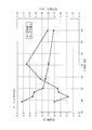
- the graph which shows the relationship between the space ratio of a rectification grid, error rate, and pressure loss in case 2 (13 inches).
- the graph which shows the relationship between the space ratio of a rectification grid, error rate, and pressure loss in case 3 (11 inches).
- FIG. 1 is a cross-sectional view of the air cleaner 10 in the present embodiment.
- the air cleaner 10 is an air flow filtering device that takes in external air, removes dust in the air and discharges it, and supplies the air from which the dust is removed to an engine or the like.
- the air cleaner 10 includes a housing 11, an outer cylinder filter 12, an inner cylinder filter 13, and a rectifying grid 18.
- the outer cylinder filter 12 and the inner cylinder filter 13 are concentrically arranged inside the housing 11.
- the housing 11 accommodates the outer cylindrical filter 12 and the inner cylindrical filter 13 for filtering air, and includes a case main body 11A and a lid member 14 for closing the open end face of the case main body 11A.
- the case main body 11A is a bottomed cylindrical body such as a synthetic resin.
- the lid member 14 is formed of a disk-like body that covers the open end face of the case main body 11A.
- a rib 141 protruding in the out-of-plane direction is formed on the outer periphery of the lid member 14, and the rib 141 engages with the outer peripheral surface of the case main body 11A.
- an intake port 15 is provided as an upstream side pipe for taking outside air into the inside of the housing 11.
- the intake port 15 is disposed eccentrically with respect to the center of the case body 11A. Then, air flows into the outer peripheral side surface of the outer cylinder filter 12.
- the open end face of the case body 11A, which is open, is closed by the lid member 14, and the air filtered by the outer cylinder filter 12 and the inner cylinder filter 13 is approximately at the center of the bottom surface 111 of the case body 11A.
- An exhaust port 16 is provided as a downstream pipe for exhausting. According to this, when the outer cylinder filter 12 is deteriorated due to dirt, the lid member 14 can be removed and the outer cylinder filter 12 can be replaced. Further, on the inner surface of the bottom surface 111 of the housing 11, an annular projection 17 is formed that protrudes annularly and has a diameter larger than the inner diameter of the exhaust port 16, and the inner cylindrical filter 13 described later 17 is engaged.
- the outer cylinder filter 12 is formed of a cylindrical portion 122 formed into a cylindrical shape by folding a general-purpose filter for filtering air taken into the inside of the housing 11 and a urethane circular shape holding one end of the cylindrical portion 122
- a holding member 123 and an annular holding member 124 made of urethane for holding the other end of the cylindrical portion 122 are provided.
- a circular holding member 123 is in contact with the bottom surface 111 of the housing 11 and is detachably attached to the outer peripheral surface of the annular projection 17.
- An annular protrusion 125 is formed on the outer surface side of the annular holding member 124, and the protrusion 125 is in contact with the lid member 14.
- the cover member 14 urges the projection 125, whereby the urethane annular holding member 124 which is an elastic body is contracted and the lid member 14 and the annular holding member 124 are in close contact with each other.
- the circular holding member 123 made of urethane which is an elastic body, presses the bottom surface 111 by urging the projection 125, the bottom surface 111 and the circular holding member 123 are in close contact with each other. Thereby, the air which has entered from the air intake port 15 flows only to the outer peripheral side surface of the cylindrical portion 122.
- the inner cylinder filter 13 further filters the air filtered by the outer cylinder filter 12, and further, prevents the contaminated air from entering the downstream side when the outer cylinder filter 12 is replaced. Further, the inner cylinder filter 13 is housed in the hollow portion 121 of the outer cylinder filter 12 and, similarly to the outer cylinder filter 12, a cylindrical portion 131 formed into a tubular shape by folding a general-purpose filter, and a cylindrical portion 131 A circular holding member 132 made of urethane, which holds one end of the above, and an annular holding member 133 made of urethane, which holds the other end of the cylindrical portion 131.
- An annular protrusion 134 is formed on the outer surface side of the circular holding member 132, and the protrusion 134 is in contact with the annular holding member 124 of the outer cylinder filter 12. Further, an annular holding member 133 is fitted and fixed to the inner circumferential surface of the annular protrusion 17.
- the rectifying grid 18 rectifies the flow of filtered air exhausted from the inside of the housing 11, and is formed by knitting a stainless steel wire in a grid shape. Moreover, the resin mold is given to the outer peripheral part of the rectification grid 18 over the perimeter. Then, the flow straightening grid 18 is welded to the annular projection 17 via the resin material 181.
- the annular holding member 124 of the outer cylinder filter 12 biases the projection 134 of the inner cylinder filter 13, the urethane annular holding member 124, which is an elastic body, is in close contact with the circular holding member 132.
- the annular holding member 133 urges the resin material 181, and the flow straightening grid 18 is pressed, so that the annular holding member 133 and the resin material 181 adhere closely. Thereby, the deformation of the rectifying grid 18 is suppressed.
- the rectifying grid 18 used in the present embodiment is the difference between the mass flow rate (actual flow rate) measured in advance at the intake port 15 side and the mass flow rate (measured flow rate) measured at the exhaust port 16 side.
- a value (hereinafter referred to as an error rate) divided by is small, and one having a low pressure loss due to the rectifying grid 18 is selected, and the specification in this embodiment is 30 mesh, wire diameter 0.29 (mm), space The rate is 43.2 (%).
- “mesh” is a unit indicating the number of meshes per inch.
- the “space factor” is calculated by the equation (1) described above with reference to FIG. The reason why the rectifying grid 18 of this specification is used will be described later.
- the rectifying grid 18 may be made of not only stainless steel but also another material, such as nickel, aluminum, copper, etc., and not only a wire mesh but also punching metal.
- the inner diameter of the inner cylinder filter 13 is substantially the same as the inner diameter of the exhaust port 16 or larger than the inner diameter of the exhaust port 16. According to this, the air filtered by the outer cylinder filter 12 and the inner cylinder filter 13 is discharged to the exhaust port 16 through the inner surface of the inner cylinder filter 13, but the inner diameter of the inner cylinder filter 13 Since the internal diameter of the exhaust port 16 is substantially the same size or larger than the internal diameter of the exhaust port 16, the disturbance of the air flow from the inner cylinder filter 13 to the exhaust port 16 is prevented. And there is no turbulence or the like. It can provide a rectifying effect to the flow of air.
- a mass flow sensor 19 as a mass flow meter is attached to the exhaust port 16 to measure the flow rate of air passing through the inside of the exhaust port 16.
- the mass flow sensor 19 measures the flow of air, it generates a detection signal and outputs it to the controller 30 as a control means.
- FIG. 3 is a schematic view showing an engine control system 20 in the present embodiment.
- the engine control system 20 includes a diesel engine (hereinafter simply referred to as an engine) 21, a variable turbocharger 24, an EGR line 25 as an exhaust gas recirculation passage, an EGR cooler 26 and an EGR valve provided in the middle of the EGR line 25. 27, the air cleaner 10 described above, a mass flow sensor 19 as a mass flow meter, and a controller 30 as control means.
- the variable turbocharger 24 is connected to the intake line 22 and the exhaust line 23 to the engine 21, and exhausts the exhaust gas of the engine 21 and a compressor 241 provided in the middle of the intake line 22 that supplies air to the engine 21. And a turbine 242 provided in the middle of the exhaust line 23.
- the turbine 242 is driven by the exhaust gas from the engine 21, and the intake air supercharged by the compressor 241 rotating with the turbine 242 is supplied to the engine 21 through the aftercooler 28.
- the variable turbocharger 24 is provided with an opening adjustment mechanism for adjusting the opening of the nozzle unit (not shown), and the controller 30 outputs a signal to the opening adjustment mechanism to open the opening of the nozzle unit. Control.
- the EGR line 25 is an exhaust gas recirculation passage branched from the exhaust line 23, shorts the intake line 22 and the exhaust line 23, extracts a part of exhaust gas of the engine 21 and takes it into the intake line 22, thereby exhausting the exhaust gas. Recirculate.
- An EGR cooler 26 and an EGR valve 27 are provided in the middle of the EGR line 25 to cool the exhaust gas returned to the intake side.
- the EGR valve 27 is an electromagnetic valve that opens and closes according to a signal output from the controller 30 and whose opening degree is controlled.
- the mass flow sensor 19 is a general-purpose mass air flow sensor (MAF sensor).
- the mass flow rate sensor 19 measures the flow rate of air passing through the exhaust port 16 and outputs a detection signal to the controller 30.
- the mass flow rate sensor 19 is attached to the downstream side of the air cleaner 10.
- FIG. 4 is a block diagram of the controller 30 used in the engine control system 20. As shown in FIG. As shown in FIG. 3, the controller 30 is electrically connected to the opening adjustment mechanism of the variable turbocharger 24, the EGR valve 27, and the mass flow sensor 19, and a detection signal output from the mass flow sensor 19. The EGR valve 27 and the nozzle portion (not shown) constituting the variable turbocharger 24 are controlled based on the above.
- the controller 30 is provided with a flow rate detection unit 31, an EGR valve opening degree control unit 32, and a nozzle opening degree control unit 33.
- the flow rate detection unit 31 detects a detection signal output from the mass flow rate sensor 19, calculates a mass flow rate, and outputs the mass flow rate to the EGR valve opening degree control unit 32 and the nozzle opening degree control unit 33. It is a thing.
- the EGR valve opening degree control unit 32 calculates the opening degree of the EGR valve 27 based on the mass flow rate output from the flow rate detection unit 31, and outputs a signal to the EGR valve 27.
- the nozzle opening degree control unit 33 calculates the nozzle opening degree of the variable turbocharger 24 based on the mass flow rate output from the flow rate detection unit 31, and outputs a signal to the opening degree adjusting mechanism.
- the mass flow sensor 19 measures the flow rate of air flowing through the exhaust port 16, and outputs a detection signal to the flow rate detection unit 31 of the controller 30.
- the flow rate detection unit 31 calculates the flow rate based on the detection signal (S1). Then, the flow rate detection unit 31 outputs the calculated flow rate to the nozzle opening degree control unit 33, and the nozzle opening degree control unit 33 calculates the opening degree of the nozzle portion of the variable turbocharger 24 based on the flow rate. (S2), and outputs a signal to the opening adjustment mechanism of the variable turbocharger 24.
- the flow rate detection unit 31 outputs the calculated flow rate to the EGR valve opening degree control unit 32, and the EGR valve opening degree control unit 32 calculates the opening degree of the EGR valve 27 based on the flow rate (S3) , And outputs a signal to the EGR valve 27.
- the opening adjustment mechanism of the variable turbocharger 24 controls the opening of the nozzle portion so as to be the calculated nozzle opening (S4).
- the EGR valve 27 controls the opening degree of the EGR valve 27 so as to be the calculated opening degree of the EGR valve 27 (S5).
- the rectifying grid 18 has a small error rate between the mass flow rate of air measured by the mass flow rate sensor 19 and the mass flow rate of air previously measured at the intake port 15 side, and pressure loss Since the low optimum one is selected, the flow rate of the air discharged from the air cleaner 10 can be measured with high accuracy regardless of the positional relationship between the outer cylinder filter 12 and the inner cylinder filter 13 or the like. Further, since the outer cylinder filter 12 and the inner cylinder filter 13 are housed inside the housing 11 of the air cleaner 10 and have a double structure, dust and the like contained in the air taken in from the outside can be reliably removed. , Air cleanliness can be improved. On the other hand, since the engine 21 is controlled based on the flow rate of air measured with high accuracy, the controller 30 can perform more precise EGR control.
- Case 1 is 15 inches
- case 2 is 13 inches
- case 3 is 11 inches
- case 4 is 10 inches.
- a plurality of sample rectification grids are disposed in the air cleaner 10 as in the previous embodiment.
- the commutation grid samples used in the experiments are shown in Tables 1-4.
- the attachment position of the outer cylinder filter 12 fluctuates due to the attachment / detachment at the time of replacement of the outer cylinder filter 12, and the air flow fluctuates, which causes an error in the flow rate. It rotated every 45 degrees, measured each error rate (%) and pressure loss (kPa), and experimented by employ
- the results are shown in FIGS. 6-9.
- the openings (mm) shown in Tables 1 to 4 are the dimensions between the wires B shown in FIG.
- the pressure drop (kPa) tends to increase as the porosity (%) decreases, and the tendency becomes stronger when it is less than 40%, and when it is less than 30%, the pressure loss becomes too large, It is assumed that sufficient air can not be supplied to the intake line 22.
- the error rate tends to increase as the space rate increases as a whole, but it is confirmed that the error rate takes the smallest value within the range of 40% to 50%.
- the error rate is the smallest, and the sample with the second smallest space rate is optimal. That is, referring to Table 3, a wire mesh with a wire diameter of 0.29 (mm) and 30 mesh is optimal.
- the error rate is the smallest, and the third smallest sample among the samples is optimal. That is, referring to Table 4, a straight mesh having a wire diameter of 0.29 (mm) and 30 mesh is optimal.
- the exhaust line 23 is not provided with the treatment device, but an exhaust gas treatment device such as a DPF (Diesel Particulate Filter) may be provided downstream of the variable turbocharger 24.
- DPF Diesel Particulate Filter
- the air cleaner and engine control system of the present invention can be suitably used for construction machines, civil engineering machines, agricultural machines, power generators, transport vehicles and the like.
Landscapes
- Engineering & Computer Science (AREA)
- Chemical & Material Sciences (AREA)
- Mechanical Engineering (AREA)
- Combustion & Propulsion (AREA)
- General Engineering & Computer Science (AREA)
- Chemical Kinetics & Catalysis (AREA)
- Physics & Mathematics (AREA)
- Manufacturing & Machinery (AREA)
- Geometry (AREA)
- General Physics & Mathematics (AREA)
- Fluid Mechanics (AREA)
- Processes For Solid Components From Exhaust (AREA)
- Exhaust-Gas Circulating Devices (AREA)
- Supercharger (AREA)
Abstract
Description
また、このようなEGRシステムにおいて、外部の空気を取り込むエアクリーナの下流側に可変ターボ過給機を設け、エアクリーナを介して取り込まれる空気を加圧してエンジンに供給するシステムも知られ、EGRバルブや可変ターボ過給機のノズルの開度制御は、コントローラによって電子的に制御される。
ここで、コントローラによる制御は、エアクリーナで濾過された空気の流量を質量流量計を用いて測定し、測定された空気の流量に基づいて行われ、質量流量計の流量測定値の精度は、コントローラによる制御の精度に大きく影響する。
このエアクリーナでは、外部から取り込まれた空気を内筒フィルタ及び外筒フィルタの二重構造で濾過しているため、排出される空気の清浄度をより向上させることができる、という利点がある。
このようなエアクリーナでは、通常内筒フィルタは、フィルタを収納する筐体内に固定されており、フィルタの汚れの状態に応じて、外筒フィルタを交換するようにしている。
しかしながら、このようなエアクリーナは、外筒フィルタ自体のフィルタ紙のバラつきや、筐体内部に固定された内筒フィルタと、装着した外筒フィルタとの位置関係で筐体内部の空気の流れが微妙に変化することがあり、単純に前記特許文献1に記載の技術を適用しただけでは、質量流量計によって空気の流量を高精度に測定できないという問題がある。
ここでの整流格子は、金網、パンチングメタル等をいう。
ここで、空間率(%)は、図2を参照し、以下の式(1)にて求められる。
空間率(%)=(B2/A2)×100・・・式(1)
ここで、線径とは、整流格子を構成する線材の太さをいう。
(エアクリーナ10の構造)
図1は、本実施形態でのエアクリーナ10の断面図である。
このエアクリーナ10は、外部の空気を取り込んで、空気中の塵埃を除去して排出し、塵埃が除去された空気をエンジン等に供給する気流濾過装置である。エアクリーナ10は、筐体11、外筒フィルタ12、内筒フィルタ13、及び整流格子18を備えている。外筒フィルタ12及び内筒フィルタ13は、筐体11の内部に同心円状に配置されている。
ケース本体11Aは、合成樹脂等の有底円筒状体である。蓋部材14は、ケース本体11Aの開口端面を覆う円板状体から構成されている。蓋部材14の外周には、面外方向に突出するリブ141が形成されており、リブ141がケース本体11Aの外周面に係合する。
円形保持部材123が、筐体11の底面111に当接され、環状突起部17の外周面に対して、着脱自在に取り付けられている。環状保持部材124の外面側には、環状の突起部125が形成され、突起部125は、蓋部材14に当接している。
すなわち、外筒フィルタ12の交換後、蓋部材14が突起部125を付勢することで、弾性体であるウレタン製の環状保持部材124が収縮し、蓋部材14と環状保持部材124とが密着する。さらに、突起部125が付勢されることで、弾性体であるウレタン製の円形保持部材123が底面111を押圧するので、底面111と円形保持部材123とが密着する。これにより、吸気口15から入ってきた空気は、筒部122の外周側面に対してのみ流れ込むようになっている。
円形保持部材132の外面側には、環状の突起部134が形成され、突起部134は、外筒フィルタ12の環状保持部材124に当接している。また、環状保持部材133が、環状突起部17の内周面に対して嵌合し、固定されている。
ここで、外筒フィルタ12の環状保持部材124が、内筒フィルタ13の突起部134を付勢するので、弾性体であるウレタン製の環状保持部材124と円形保持部材132とが密着する。突起部134が環状保持部材124に付勢されることで、環状保持部材133は樹脂材181を付勢し、整流格子18を押さえ付けて、環状保持部材133と樹脂材181とが密着する。これにより、整流格子18の変形を抑制している。
なお、「メッシュ」とは、1インチ当たりの網目の数を示す単位である。「空間率」は、図2を参照して、前述した式(1)にて算出される。この仕様の整流格子18が使用されている理由については、後述する。
また、整流格子18は、ステンレス製のみならず、別の材質であってもよく、例えば、ニッケル、アルミニウム、銅等があり、金網のみならず、パンチングメタルであってもよい。
外部の空気は、エアクリーナ10の吸気口15から筐体11内部に取り込まれると、まず外筒フィルタ12で濾過され、次に内筒フィルタ13で濾過される。そして、濾過された空気は、整流格子18で空気の流れが整流化され、排気口16から排気される。
図3は、本実施形態でのエンジン制御システム20を示す概略図である。
エンジン制御システム20は、ディーゼルエンジン(以下、単にエンジンと称する)21、可変ターボ過給機24、排気再循環通路としてのEGRライン25、EGRライン25の途中に設けられたEGRクーラ26およびEGRバルブ27、前述したエアクリーナ10、質量流量計としての質量流量センサ19、及び制御手段としてのコントローラ30を備えている。
タービン242は、エンジン21からの排気ガスにて駆動され、このタービン242と共に回転するコンプレッサ241で過給された吸気がアフタークーラ28を通って、エンジン21に供給される。ここで、可変ターボ過給機24には、図示しないノズル部の開度を調整する開度調整機構が設けられ、コントローラ30は、開度調整機構に信号を出力し、ノズル部の開度を制御する。
EGRバルブ27は、コントローラ30から出力された信号により開閉し、開度が制御される電磁弁である。
図4は、エンジン制御システム20に用いられるコントローラ30のブロック図である。
図3に示すように、コントローラ30は、可変ターボ過給機24の開度調整機構、EGRバルブ27、および質量流量センサ19にそれぞれ電気的に接続され、質量流量センサ19から出力される検出信号に基づいてEGRバルブ27及び可変ターボ過給機24を構成するノズル部(図示略)を制御する。
コントローラ30には、流量検出部31と、EGRバルブ開度制御部32と、ノズル開度制御部33とが設けられている。
EGRバルブ開度制御部32は、流量検出部31から出力された質量流量に基づいて、EGRバルブ27の開度を算出し、EGRバルブ27へ信号を出力するものである。
ノズル開度制御部33は、流量検出部31から出力された質量流量に基づいて、可変ターボ過給機24のノズル開度を算出し、開度調整機構へ信号を出力するものである。
質量流量センサ19は、排気口16を流れる空気流量を計測し、検出信号をコントローラ30の流量検出部31へ出力する。流量検出部31は、この検出信号に基づいて、流量を算出する(S1)。そして、流量検出部31は、算出した流量をノズル開度制御部33へ出力し、ノズル開度制御部33は、この流量に基づいて、可変ターボ過給機24のノズル部の開度を算出し(S2)、信号を可変ターボ過給機24の開度調整機構に出力する。また、流量検出部31は、算出した流量をEGRバルブ開度制御部32へ出力し、EGRバルブ開度制御部32は、この流量に基づいて、EGRバルブ27の開度を算出し(S3)、信号をEGRバルブ27に出力する。次に、可変ターボ過給機24の開度調整機構は、算出されたノズル開度となるように、ノズル部の開度を制御する(S4)。また、EGRバルブ27は、算出されたEGRバルブ27の開度となるように、EGRバルブ27の開度を制御する(S5)。
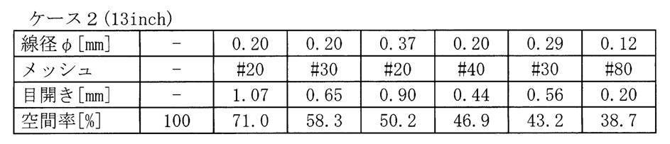
前述した実施形態と同様に、エアクリーナ10内に複数のサンプルの整流格子を配置する。実験で使用される整流格子のサンプルは、表1~表4に示している。外筒フィルタ12の交換時の着脱等により、外筒フィルタ12の取り付け位置が変動する等して、空気の流れが変動し、流量に誤差を生じることから、本実験では、外筒フィルタ12を45°毎に回転させ、それぞれの誤差率(%)および圧力損失(kPa)を計測し、この中で誤差率(%)が最も小さくなる整流格子18を採用する実験を行った。この結果は、図6~図9に示している。
表1~表4に示す目開き(mm)とは、図2に示す線材間Bの寸法である。



1.圧力損失(kPa)は、空間率(%)が小さくなるに従って、大きくなる傾向にあり、その傾向は、40%未満になると、一層強くなり、30%未満になると、圧力損失が大きくなり過ぎ、吸気ライン22に十分な空気を供給できなくなることが推認される。
2.一方、誤差率は、全体として空間率が増加するに従って、大きくなる傾向があるが、40%~50%の範囲内で誤差率が最も小さな数値を取ることが確認される。
3.エアクリーナ10として十分に機能させるには、圧力損失があまり大きくならない空間率30%以上、誤差率が最も小さくなり得る空間率50%以下の整流格子を採用するのが好ましい。
図6に示すケース1(15インチ)でのグラフを参照すると、誤差率が最小であり、サンプルの中で空間率が3番目に小さいものが最適となる。すなわち、表1を参照すると、線径0.29(mm)、30メッシュの整流格子が最適である。
図7に示すケース2(13インチ)でのグラフを参照すると、誤差率が最小であり、サンプルの中で空間率が2番目に小さいものが最適となる。すなわち、表2を参照すると、線径0.29(mm)、30メッシュの整流格子が最適である。
図9に示すケース4(10インチ)でのグラフを参照すると、誤差率が最小であり、サンプルの中で空間率が3番目に小さいものが最適となる。すなわち、表4を参照すると、線径0.29(mm)、30メッシュの整流格子が最適である。
従って、上記に開示した形状、数量などを限定した記載は、本発明の理解を容易にするために例示的に記載したものであり、本発明を限定するものではないから、それらの形状、数量などの限定の一部もしくは全部の限定を外した部材の名称での記載は、本発明に含まれるものである。
Claims (6)
- 外部の空気を取り込んで該空気中の塵埃を除去して排出するエアクリーナであって、
同心円状に配置される内筒フィルタ及び外筒フィルタと、
前記内筒フィルタ及び外筒フィルタを収納し、有底筒状体の開口端面が蓋部材で塞がれた筐体とを備え、
前記筐体は、前記有底筒状体の外周側面に設けられ、外部の空気を該筐体の内部に取り込む上流側配管と、前記有底筒状体の空気流れ方向下流側の底面の略中央に設けられ、前記上流側配管から取り込まれ、前記内筒フィルタ及び前記外筒フィルタで濾過された空気を排出する下流側配管とを備え、
前記下流側配管の内部には、該下流側配管中の空気の流量を計測する質量流量計が設けられ、
前記質量流量計の上流側には、前記下流側配管内の空気の流れを整流する整流格子が設けられている
ことを特徴とするエアクリーナ。 - 請求項1に記載のエアクリーナにおいて、
前記整流格子の外径寸法は、前記下流側配管の配管径と略同一か、または前記下流側配管の配管径よりも大きくなっており、前記底面と前記内筒フィルタとの間に装着されている
ことを特徴とするエアクリーナ。 - 請求項1又は請求項2に記載のエアクリーナにおいて、
前記内筒フィルタの内径寸法は、前記下流側配管の内径と略同一か、または前記下流側配管の内径よりも大きくなっている
ことを特徴とするエアクリーナ。 - 請求項1ないし請求項3のいずれかに記載のエアクリーナにおいて、
前記整流格子は、金網状の格子部材から構成され、該整流格子の空間率は、30%~50%である
ことを特徴とするエアクリーナ。 - 請求項4に記載のエアクリーナにおいて、
前記整流格子には、線径0.2mm以上の線材を格子状に編んで形成されている
ことを特徴とするエアクリーナ。 - エンジンの排気ガスの一部を吸気側に再循環させる排気再循環通路中に設けられるEGRバルブと、
請求項1ないし請求項5のいずれかに記載のエアクリーナと、
前記エンジンからの排気ガスにより駆動され、前記エアクリーナで濾過された空気を吸入、加圧して前記エンジンに供給する可変ターボ過給機と、
前記EGRバルブ及び前記可変ターボ過給機を制御する制御手段とを備え、
前記制御手段は、
前記エアクリーナに設けられる質量流量計からの信号を検出する流量検出部と、
前記EGRバルブの開度制御を行うEGRバルブ開度制御部と、
前記可変ターボ過給機を構成するノズル開度制御を行うノズル開度制御部とを備え、
前記EGRバルブ開度制御部及び前記ノズル開度制御部は、前記流量検出部で検出された検出信号に基づいて、前記EGRバルブ及び前記ノズルの開度制御を行う
ことを特徴とするエンジン制御システム。
Priority Applications (4)
| Application Number | Priority Date | Filing Date | Title |
|---|---|---|---|
| CN200980129318.7A CN102105667B (zh) | 2008-08-01 | 2009-07-21 | 空气过滤器及发动机控制系统 |
| SE1150172A SE1150172A1 (sv) | 2008-08-01 | 2009-07-21 | Luftrenare och motorstyrsystem |
| US13/057,094 US8844286B2 (en) | 2008-08-01 | 2009-07-21 | Air cleaner, and engine control system |
| KR1020117002282A KR101237844B1 (ko) | 2008-08-01 | 2009-07-21 | 에어 클리너 및 엔진 제어 시스템 |
Applications Claiming Priority (2)
| Application Number | Priority Date | Filing Date | Title |
|---|---|---|---|
| JP2008199449A JP5219679B2 (ja) | 2008-08-01 | 2008-08-01 | エアクリーナ、及びエンジン制御システム |
| JP2008-199449 | 2008-08-01 |
Publications (1)
| Publication Number | Publication Date |
|---|---|
| WO2010013613A1 true WO2010013613A1 (ja) | 2010-02-04 |
Family
ID=41610313
Family Applications (1)
| Application Number | Title | Priority Date | Filing Date |
|---|---|---|---|
| PCT/JP2009/063017 Ceased WO2010013613A1 (ja) | 2008-08-01 | 2009-07-21 | エアクリーナ、及びエンジン制御システム |
Country Status (6)
| Country | Link |
|---|---|
| US (1) | US8844286B2 (ja) |
| JP (1) | JP5219679B2 (ja) |
| KR (1) | KR101237844B1 (ja) |
| CN (1) | CN102105667B (ja) |
| SE (1) | SE1150172A1 (ja) |
| WO (1) | WO2010013613A1 (ja) |
Cited By (2)
| Publication number | Priority date | Publication date | Assignee | Title |
|---|---|---|---|---|
| CN102536461A (zh) * | 2010-11-22 | 2012-07-04 | 通用电气公司 | 结合涡轮发动机系统使用的滤筒组件 |
| WO2013035602A1 (ja) * | 2011-09-05 | 2013-03-14 | 株式会社小松製作所 | エアクリーナ |
Families Citing this family (18)
| Publication number | Priority date | Publication date | Assignee | Title |
|---|---|---|---|---|
| US8828112B2 (en) * | 2010-09-07 | 2014-09-09 | Hdt Expeditionary Systems, Inc. | Air filter |
| CN102454489A (zh) * | 2010-10-15 | 2012-05-16 | 北汽福田汽车股份有限公司 | 气体整流装置以及发动机的进气系统 |
| JP5912276B2 (ja) * | 2011-03-29 | 2016-04-27 | 株式会社クボタ | エアクリーナ |
| JP2013053543A (ja) * | 2011-09-02 | 2013-03-21 | Kubota Corp | 空気浄化装置 |
| KR102032001B1 (ko) * | 2011-10-31 | 2019-10-14 | 도날드슨 컴파니, 인코포레이티드 | 에어 필터 어셈블리 |
| NL2008494C2 (en) * | 2012-03-15 | 2013-09-18 | Global Power Netherlands B V | Screen panel for covering at least partly an air intake opening of an air inlet house of a combustion engine or a compressor. |
| US10914229B2 (en) | 2012-09-14 | 2021-02-09 | Ford Global Technologies, Llc | Charge air cooler condensation dispersion element |
| DE102013012013A1 (de) * | 2013-07-18 | 2015-01-22 | Mann + Hummel Gmbh | Stützrohr, Filterelement und Filtersystem mit einem Stützrohr sowie Verfahren und Vorrichtung zur Herstellung des Stützrohrs |
| DE102013218217A1 (de) * | 2013-09-11 | 2015-03-26 | Mahle International Gmbh | Luftfilter |
| CN104747328A (zh) * | 2015-03-06 | 2015-07-01 | 广西华原过滤系统股份有限公司 | 一种新型空气滤清器滤芯 |
| CN105833641B (zh) * | 2016-04-19 | 2018-01-02 | 贾克 | 双滤芯反向旋转超重力湿法除尘器 |
| CN106321410A (zh) * | 2016-08-23 | 2017-01-11 | 柳州市国正机电物资有限责任公司 | 压缩机空气滤清器 |
| JP2018035570A (ja) * | 2016-08-31 | 2018-03-08 | 住友建機株式会社 | ショベル |
| GB2586664B (en) * | 2019-08-30 | 2022-03-02 | Indufil BV | Flow optimized filter |
| DE102019006128A1 (de) * | 2019-08-30 | 2021-03-04 | Deutz Aktiengesellschaft | Saugmotor mit Reflektor Ansaugsystem |
| DE102020128475B4 (de) | 2020-10-29 | 2022-11-17 | Mann+Hummel Gmbh | Strömungsgleichrichteranordnung, Strömungsgleichrichter, Strömungsgleichrichterset und Verfahren zur Montage einer Strömungsgleichrichteranordnung |
| CN112555068B (zh) * | 2020-12-04 | 2021-11-12 | 隆鑫通用动力股份有限公司 | 空滤器及工作机 |
| CN119345840B (zh) * | 2023-07-11 | 2025-12-09 | 中国石油化工股份有限公司 | 一种气井井口气液计量装置 |
Citations (6)
| Publication number | Priority date | Publication date | Assignee | Title |
|---|---|---|---|---|
| JPH0510771U (ja) * | 1991-07-16 | 1993-02-12 | 日産工機株式会社 | 空気整流部を備えたエアクリーナー |
| JP2001286715A (ja) * | 2000-04-07 | 2001-10-16 | Toyo Element Industry Co Ltd | フィルタエレメント及びフィルタ装置 |
| JP2001289132A (ja) * | 2000-04-04 | 2001-10-19 | Denso Corp | 吸気装置 |
| JP2003315126A (ja) * | 2002-04-18 | 2003-11-06 | Hitachi Ltd | 空気流量計 |
| US20060162303A1 (en) * | 2005-01-27 | 2006-07-27 | Gunderson Larry T | Performance air filtration cartridge |
| JP2008106636A (ja) * | 2006-10-24 | 2008-05-08 | Mazda Motor Corp | エンジンの異常検出装置 |
Family Cites Families (16)
| Publication number | Priority date | Publication date | Assignee | Title |
|---|---|---|---|---|
| DE4013351A1 (de) * | 1989-04-25 | 1990-10-31 | Mitsubishi Motors Corp | Wirbelstroemungsmesser |
| US5253517A (en) * | 1990-05-30 | 1993-10-19 | Siemens Aktiengesellschaft | Flow converter |
| DE59010035D1 (de) | 1990-05-30 | 1996-02-15 | Siemens Ag | Strömungswandler |
| US5547480A (en) * | 1994-01-21 | 1996-08-20 | Donaldson Company, Inc. | Cylindrical air filter with radially directed seal |
| JP3245362B2 (ja) | 1996-08-05 | 2002-01-15 | 株式会社日立製作所 | 空気流量測定装置用整流格子 |
| JP3713865B2 (ja) * | 1997-01-23 | 2005-11-09 | 株式会社デンソー | 内燃機関の吸気装置 |
| US5953920A (en) * | 1997-11-21 | 1999-09-21 | Regent Of The University Of California | Tapered pulse tube for pulse tube refrigerators |
| US6797027B2 (en) * | 2001-04-11 | 2004-09-28 | Donaldson Company, Inc. | Filter assemblies and systems for intake air for fuel cells |
| DE10126676A1 (de) | 2001-06-01 | 2002-12-05 | Bosch Gmbh Robert | Vorrichtung zur Bestimmung zumindest eines Parameters eines in einer Leitung strömenden Mediums mit einem Filter zur Aufnahme von Schadstoffen in der Leitung |
| US6951697B2 (en) * | 2001-09-11 | 2005-10-04 | Donaldson Company, Inc. | Integrated systems for use with fuel cells, and methods |
| JP2003120445A (ja) * | 2001-10-05 | 2003-04-23 | Tokyo Roki Co Ltd | エアクリーナ |
| JP3873742B2 (ja) * | 2001-12-28 | 2007-01-24 | いすゞ自動車株式会社 | 可変容量ターボチャージャの制御装置 |
| DE102004000048B4 (de) * | 2004-11-17 | 2008-08-14 | Mann + Hummel Gmbh | Luftfilter |
| DE102008049806A1 (de) * | 2008-09-30 | 2010-04-01 | Man Nutzfahrzeuge Ag | Anordnung einer Luftmassen-Durchflussmesseinrichtung in einem Ansaugsystem einer Brennkraftmaschine |
| DE102010029217A1 (de) * | 2010-05-21 | 2011-11-24 | Robert Bosch Gmbh | Vorrichtung zur Erfassung einer Eigenschaft eines strömenden fluiden Mediums |
| JP2014218894A (ja) * | 2011-09-05 | 2014-11-20 | 株式会社小松製作所 | エアクリーナ |
-
2008
- 2008-08-01 JP JP2008199449A patent/JP5219679B2/ja active Active
-
2009
- 2009-07-21 US US13/057,094 patent/US8844286B2/en active Active
- 2009-07-21 WO PCT/JP2009/063017 patent/WO2010013613A1/ja not_active Ceased
- 2009-07-21 SE SE1150172A patent/SE1150172A1/sv not_active Application Discontinuation
- 2009-07-21 CN CN200980129318.7A patent/CN102105667B/zh active Active
- 2009-07-21 KR KR1020117002282A patent/KR101237844B1/ko not_active Expired - Fee Related
Patent Citations (6)
| Publication number | Priority date | Publication date | Assignee | Title |
|---|---|---|---|---|
| JPH0510771U (ja) * | 1991-07-16 | 1993-02-12 | 日産工機株式会社 | 空気整流部を備えたエアクリーナー |
| JP2001289132A (ja) * | 2000-04-04 | 2001-10-19 | Denso Corp | 吸気装置 |
| JP2001286715A (ja) * | 2000-04-07 | 2001-10-16 | Toyo Element Industry Co Ltd | フィルタエレメント及びフィルタ装置 |
| JP2003315126A (ja) * | 2002-04-18 | 2003-11-06 | Hitachi Ltd | 空気流量計 |
| US20060162303A1 (en) * | 2005-01-27 | 2006-07-27 | Gunderson Larry T | Performance air filtration cartridge |
| JP2008106636A (ja) * | 2006-10-24 | 2008-05-08 | Mazda Motor Corp | エンジンの異常検出装置 |
Cited By (4)
| Publication number | Priority date | Publication date | Assignee | Title |
|---|---|---|---|---|
| CN102536461A (zh) * | 2010-11-22 | 2012-07-04 | 通用电气公司 | 结合涡轮发动机系统使用的滤筒组件 |
| US8997450B2 (en) | 2010-11-22 | 2015-04-07 | Bha Altair, Llc | Filter cartridge assembly for use with turbine engine systems |
| WO2013035602A1 (ja) * | 2011-09-05 | 2013-03-14 | 株式会社小松製作所 | エアクリーナ |
| JP2014218894A (ja) * | 2011-09-05 | 2014-11-20 | 株式会社小松製作所 | エアクリーナ |
Also Published As
| Publication number | Publication date |
|---|---|
| KR101237844B1 (ko) | 2013-02-27 |
| CN102105667A (zh) | 2011-06-22 |
| US20110219768A1 (en) | 2011-09-15 |
| SE1150172A1 (sv) | 2011-02-25 |
| CN102105667B (zh) | 2014-08-13 |
| US8844286B2 (en) | 2014-09-30 |
| JP2010037977A (ja) | 2010-02-18 |
| KR20110025860A (ko) | 2011-03-11 |
| JP5219679B2 (ja) | 2013-06-26 |
Similar Documents
| Publication | Publication Date | Title |
|---|---|---|
| JP5219679B2 (ja) | エアクリーナ、及びエンジン制御システム | |
| RU2704382C9 (ru) | Система (варианты) и способ обнаружения твердых частиц | |
| CN101165321B (zh) | 微粒物质传感器 | |
| CN102844553B (zh) | 排气传感器 | |
| EP2236786B1 (en) | Particulate matter concentration measuring apparatus | |
| US20130133631A1 (en) | System to measure parameters of a particulate laden flow | |
| US8056405B2 (en) | Particulate matter concentration measuring apparatus | |
| KR20080034801A (ko) | 배기 가스 정화 장치 | |
| US10006416B2 (en) | Air filter | |
| US20130008243A1 (en) | Air flow measuring device | |
| JP2010138845A (ja) | 吸気整流装置 | |
| CN107631966B (zh) | 用于排气微粒物质感测的方法和系统 | |
| JP5736662B2 (ja) | 排気センサー | |
| CN107916979B (zh) | 用于排气微粒物质感测的方法和系统 | |
| US20180347437A1 (en) | Method and system for exhaust particulate matter sensing | |
| JP2011075538A (ja) | 微粒子濃度測定装置 | |
| US10267204B2 (en) | Method and system for exhaust particulate matter sensing | |
| JP5520870B2 (ja) | 空気浄化装置 | |
| CN112673163B (zh) | 空气滤清器 | |
| JP2010112297A (ja) | 内燃機関の吸気装置 | |
| JP5324408B2 (ja) | Egrクーラ | |
| JP6036635B2 (ja) | 吸気装置 | |
| JP2019148501A (ja) | 流体用センサ |
Legal Events
| Date | Code | Title | Description |
|---|---|---|---|
| WWE | Wipo information: entry into national phase |
Ref document number: 200980129318.7 Country of ref document: CN |
|
| 121 | Ep: the epo has been informed by wipo that ep was designated in this application |
Ref document number: 09802856 Country of ref document: EP Kind code of ref document: A1 |
|
| ENP | Entry into the national phase |
Ref document number: 20117002282 Country of ref document: KR Kind code of ref document: A |
|
| NENP | Non-entry into the national phase |
Ref country code: DE |
|
| WWE | Wipo information: entry into national phase |
Ref document number: 13057094 Country of ref document: US |
|
| 122 | Ep: pct application non-entry in european phase |
Ref document number: 09802856 Country of ref document: EP Kind code of ref document: A1 |