WO2010010781A1 - 落下検知装置、磁気ディスク装置および携帯電子機器 - Google Patents
落下検知装置、磁気ディスク装置および携帯電子機器 Download PDFInfo
- Publication number
- WO2010010781A1 WO2010010781A1 PCT/JP2009/061559 JP2009061559W WO2010010781A1 WO 2010010781 A1 WO2010010781 A1 WO 2010010781A1 JP 2009061559 W JP2009061559 W JP 2009061559W WO 2010010781 A1 WO2010010781 A1 WO 2010010781A1
- Authority
- WO
- WIPO (PCT)
- Prior art keywords
- value
- determination
- fall
- detection
- detection device
- Prior art date
- Legal status (The legal status is an assumption and is not a legal conclusion. Google has not performed a legal analysis and makes no representation as to the accuracy of the status listed.)
- Ceased
Links
Images


Classifications
-
- G—PHYSICS
- G11—INFORMATION STORAGE
- G11B—INFORMATION STORAGE BASED ON RELATIVE MOVEMENT BETWEEN RECORD CARRIER AND TRANSDUCER
- G11B19/00—Driving, starting, stopping record carriers not specifically of filamentary or web form, or of supports therefor; Control thereof; Control of operating function ; Driving both disc and head
- G11B19/02—Control of operating function, e.g. switching from recording to reproducing
- G11B19/04—Arrangements for preventing, inhibiting, or warning against double recording on the same blank or against other recording or reproducing malfunctions
- G11B19/041—Detection or prevention of read or write errors
- G11B19/043—Detection or prevention of read or write errors by detecting a free-fall condition
-
- G—PHYSICS
- G01—MEASURING; TESTING
- G01P—MEASURING LINEAR OR ANGULAR SPEED, ACCELERATION, DECELERATION, OR SHOCK; INDICATING PRESENCE, ABSENCE, OR DIRECTION, OF MOVEMENT
- G01P15/00—Measuring acceleration; Measuring deceleration; Measuring shock, i.e. sudden change of acceleration
- G01P15/18—Measuring acceleration; Measuring deceleration; Measuring shock, i.e. sudden change of acceleration in two or more dimensions
Definitions
- the present invention relates to a fall detection device that detects whether or not the device is in a fall state based on acceleration, a magnetic disk device including the fall detection device, and a portable electronic device.
- patent document 1 is disclosed as an apparatus which detects the fall state of an apparatus.
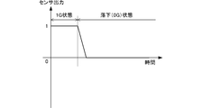
- FIG. 1 shows how the output (az) of the acceleration sensor in the Z-axis direction of Patent Document 1 changes from 1 to almost 0.
- an arithmetic circuit that calculates the magnitude of acceleration from an output signal of an acceleration sensor, a comparison circuit that compares whether or not the magnitude of acceleration is a value close to 0, and the acceleration are almost zero. Whether or not a state in which all the accelerations in the (X-axis, Y-axis, Z-axis) are substantially zero continues for the reference duration. For example, it is determined whether or not the magnetic disk device is free-falling.
- the determination circuit determines that the output of all three axes is almost “0” when the output is almost 0 for the reference time or more.
- the acceleration sensor has variations in its manufacture, and variations in characteristics due to changes in temperature and changes with time, the following problems arise in the above-described determination method.
- the fall determination becomes impossible.
- the threshold value is set to a large value in consideration of variations in the characteristics of the acceleration sensor, malfunctions such as erroneous determination of “falling” even though the vehicle is not falling will increase.
- the variation in the characteristics of the acceleration sensor can be calibrated (corrected) by several methods. For this reason, a correction circuit is separately required, which is a factor that hinders downsizing and cost reduction.
- an object of the present invention is to eliminate the problem of variation in the characteristics of the acceleration sensor to prevent the drop detection from becoming impossible, to suppress a malfunction, and to achieve a small and low cost drop detection device, and a magnetic device equipped with the fall detection device.
- a disk device and a portable electronic device To provide a disk device and a portable electronic device.
- a fall detection device that detects fall based on an output signal of an acceleration sensor, Acceleration detecting means for obtaining a detection value corresponding to acceleration in three orthogonal directions; A determination value that is a difference with respect to a detection value in the reference axial direction among the detection values in the three axial directions detected by the acceleration detecting means is obtained, and a determination preliminary state in which the determination value is within a predetermined value range is predetermined for a predetermined duration.
- Drop determination output means for generating a falling state signal when it lasts for more than a time.
- the detection value of the acceleration detection means is a value determined according to a steady error such as an offset and acceleration. During the fall, even if the detected value of the acceleration sensor does not become substantially zero, the constant value corresponding to the acceleration 0 is continuously output, and the determination value is also kept within a predetermined range.
- the falling state signal indicates that the vehicle is falling.
- a falling state canceling unit that cancels the falling state signal when the preliminary determination state exceeds an upper limit time longer than the duration. Even if it is not actually falling but in the 1G state, if the acceleration sensor is stationary, the detected value remains constant. Therefore, even in that case, the judgment value may accidentally keep a value within a predetermined range. At this time, the falling state signal is generated, and the magnetic disk device or portable electronic device on which the fall detection device is mounted is shocked. The prepared process is executed. This operation is not a fatal malfunction in which a falling state signal is not generated even though the vehicle is actually falling, but is a malfunction to the safe side.
- the preliminary determination state is continued for a longer time than the falling time, and therefore the falling state signal is released by the falling state release means. Therefore, the fall determination can be performed again.
- Steady state detection value storage means for storing the detected values in the three axial directions when the falling state releasing means performs the release, and the detected values in the three axial directions are stored in the steady state detected value storage means.
- a prohibiting unit that prohibits the fall detection determination or prohibits the output of the fall determination result when the stored value matches or approximates within a predetermined value range.
- a magnetic disk device including the fall detection device, wherein a head for recording or reading data on the magnetic disk, and when the fall detection device generates the falling state signal, the head is Head retraction means for retreating to the retreat area.
- the magnetic disk device can be protected against dropping.
- a portable electronic device including the fall detection device and a device capable of handling an impact, and when the fall detection device generates the falling state signal, the impact countermeasure processing is performed on the device.
- Shock countermeasure processing means for applying for applying thereby, the safety of the portable electronic device is enhanced by effectively controlling the device capable of handling the shock.
- the fall determination can be performed even if the output signal of the acceleration sensor includes a stationary error such as an offset.
- the falling state release means even if the 1G state is erroneously determined as “falling”, the falling state signal is subsequently released, so that the drop determination can be performed again.
- FIG. 3 is a flowchart illustrating a processing procedure in which a control unit 74 illustrated in FIG. 2 performs drop detection based on an output value of an A / D converter 72. It is a flowchart showing the process sequence in the control part of the fall detection apparatus which concerns on 2nd Embodiment.
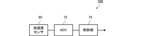
- FIG. 2 is a block diagram showing the configuration of the fall detection device according to the first embodiment.
- the fall detection device 100 includes an acceleration sensor 60 that detects acceleration and outputs an analog voltage signal corresponding to the acceleration, an A / D converter 72 that converts the output voltage of the acceleration sensor 60 into digital data, and an A / D converter 72.
- the control unit 74 is configured to detect a drop based on the output data and output the detection result to the outside (host device).
- the acceleration sensor 60 corresponds to “acceleration detecting means” according to the present invention.
- the acceleration sensor 60 includes three acceleration sensors that detect accelerations in the X-axis direction, the Y-axis direction, and the Z-axis direction that are orthogonal to each other, and the A / D converter 72 converts the output voltage of each acceleration sensor into digital data. These are output as detected values ax, ay, az of accelerations in the respective axial directions.
- the control unit 74 performs the fall determination by a process described later.
- acceleration sensor 60 various types of acceleration sensors such as a piezoelectric type, a piezoresistive type, and a capacitive type can be used.
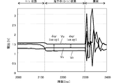
- FIG. 3 shows an example of the passage of time of the output voltages Vx, Vy, Vz and detected values az, ay, az of the respective axes of the acceleration sensor 60 before and after dropping.
- the vertical axis represents the detected value of each axis of the acceleration sensor 60 in voltage
- the horizontal axis represents the elapsed time t [ms].
- the detected value (voltage) of each axis of the acceleration sensor 60 maintains a predetermined value. If it is in a falling state (0G) at a certain time, the detected value (voltage) of each axis of the acceleration sensor 60 maintains a value corresponding to 0G. Thereafter, the output of each axis of the acceleration sensor 60 greatly fluctuates by colliding with the floor or the ground.
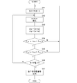
- FIG. 4 is a flowchart showing a processing procedure in which the control unit 74 shown in FIG. 2 performs drop detection based on the output value of the A / D converter 72.
- ax is a detection value of an acceleration sensor that detects acceleration in the x-axis direction (A / D converted value of the output voltage of the acceleration sensor)
- ay is a detection value of an acceleration sensor that detects acceleration in the y-axis direction
- az is a detection value of an acceleration sensor that detects acceleration in the z-axis direction.
- a timer is started (S11), and detection values ax, ay, and az of the acceleration sensor 60 are read (S12).
- an absolute value dxy of an ax difference with respect to ay is obtained, and an absolute value dzy of an az difference with respect to ay is obtained (S13). Subsequently, it is determined whether or not the absolute values dxy and dzy of the two difference values are within a range of ⁇ xy ⁇ ⁇ and a range of ⁇ zy ⁇ ⁇ described later (S14, S15).
- steps S14 and S15 are both “Yes”, and steps S12 to S15 are repeated until the “preliminary determination state” reaches a predetermined duration T.
- the process of S16 is repeated (S16 ⁇ S12 ⁇ ).
- a falling state signal is output (S17). Steps S13 to S17 correspond to “drop determination output means” described in claim 2.
- drop detection is performed.
- the determination is made on the basis of the absolute value of the difference between the detected values between the two axes in the acceleration of the three orthogonal axes.
- the detected value (ax, ay, az) by the acceleration sensor has a relationship of (gx + ⁇ x, gy + ⁇ y, gz + ⁇ z) with respect to the actual acceleration (gx, gy, gz).
- the sensor output is ( ⁇ x, ⁇ y, ⁇ z). Therefore, if these are larger than the threshold value, they are not regarded as falling even in the weightless state. Or, a correction circuit for making them zero is required.
- the output value ( ⁇ x, ⁇ y, ⁇ z) of each axis at 0G of the acceleration sensor can be obtained in advance with the acceleration detection axis kept horizontal for each acceleration sensor of each axis, and based on that value
- may be determined in advance.
- the relative voltage of the x and z axes with respect to the y axis is used as the determination value.
- the reference axis may be the x and z axes.
- FIG. 5 is a flowchart showing a processing procedure in the control unit 74 shown in FIG. First, a timer is started (S21), and detection values ax, ay, and az of the acceleration sensor 60 are read (S22).
- an absolute value dxy of an ax difference with respect to ay is obtained, and an absolute value dzy of an az difference with respect to ay is obtained (S23). Subsequently, it is determined whether or not the absolute values dxy and dzy of the two difference values are within the range of ⁇ xy ⁇ ⁇ and the range of ⁇ zy ⁇ ⁇ (S24, S25).
- the ranges ⁇ xy ⁇ ⁇ and ⁇ zy ⁇ ⁇ are the same as those shown in the first embodiment.
- the falling state signal is output (S26 ⁇ S27).
- step S29 corresponds to the “falling state canceling means” described in claim 2.
- step S27 if the absolute value dxy or dzy of the difference value between the detected values of the two axes fluctuates so as to exceed the above ⁇ xy ⁇ ⁇ range or ⁇ zy ⁇ ⁇ range, the fall will occur. It is considered that the vehicle is not in the middle (it is a collision state during normal movement or after dropping), and the falling state signal is canceled (S24, S25 ⁇ S29).
- the fall detection device According to the fall detection device according to the second embodiment, even if the falling state signal is once output even though it is not in the 1G state, that is, the falling (0G) state, Since the falling state signal is canceled, there is no inconvenience that the falling state signal continues to be output.
- sx, sy, and sz are data serving as a basis for prohibiting the fall detection determination based on ax, ay, and az or prohibiting the output of the fall determination result. If the detected values ax, ay, and az of the three axes read in step S33 coincide with sx, sy, and sz within a predetermined error range, the subsequent drop determination process is not performed (S34). ⁇ S35 ⁇ S36 ⁇ S31).
- Step S43 corresponds to “steady state detection value storage means” described in claim 3. Further, the above steps S33, S34 to S36 correspond to “prohibiting means”.
- FIG. 7 is a block diagram showing a configuration of a magnetic disk device such as a hard disk drive device.
- the read / write circuit 202 uses the head 201 to read or write data written on a track on the magnetic disk.
- the control circuit 200 performs data read / write control via the read / write circuit 202 and communicates this read / write data with the host device via the interface 205.
- the control circuit 200 controls the spindle motor 204 and controls the voice coil motor 203.
- the configuration of the fall detection device 100 is as shown in the first to fourth embodiments.
- the control circuit 200 reads the fall detection signal from the fall detection device 100, and when in the fall state, controls the voice coil motor 203 to retract the head 201 to the retract area.
- the control circuit 200 reads the fall detection signal from the fall detection device 100, and when in the fall state, controls the voice coil motor 203 to retract the head 201 to the retract area.
- FIG. 8 is a block diagram showing the configuration of a portable electronic device such as a notebook computer or a music / video playback device with a built-in hard disk drive device.
- the configuration of the drop detection device 100 is as shown in the first to fourth embodiments.
- the device 301 is a device that needs to be protected from an impact caused by a collision at the time of falling, and is a device capable of taking countermeasures therefor. For example, a hard disk drive device.
- the control circuit 300 controls the device 301 based on the output signal of the fall detection device 100. For example, when a falling state signal is received from the fall detection device 100, the device 301 is controlled in preparation for an impact when dropped.
Landscapes
- Physics & Mathematics (AREA)
- General Physics & Mathematics (AREA)
- Time Recorders, Dirve Recorders, Access Control (AREA)
- Moving Of Head For Track Selection And Changing (AREA)
- Moving Of The Head To Find And Align With The Track (AREA)
Abstract
Description
図1は、特許文献1のZ軸方向の加速度センサの出力(az)が1からほぼ0に変化する様子を示している。特許文献1には、加速度センサの出力信号から加速度の大きさを算出する演算回路と、加速度の大きさが0付近の値になったか否かを比較する比較回路と、加速度がほぼ0になって所定時間継続したか否かを判定する継続判定回路を備えていて、(X軸,Y軸,Z軸)の全ての加速度がほぼ0となる状態が基準継続時間の間継続したか否かによって、例えば磁気ディスク装置が自由落下しているか否かを判別する。
(2)加速度センサの特性バラツキを考慮して上記しきい値を予め大きめに設定すると、落下していないにも拘わらず「落下中」と誤判定するといった誤動作が増すことになる。
(3)加速度センサの特性バラツキは幾つかの方法で校正(補正)可能であるが、そのために補正用回路が別途必要となり、小型化・低コスト化を阻む要因となる。
(1)加速度センサの出力信号を基に落下検知を行う落下検知装置であって、
直交3軸方向の加速度に応じた検出値を求める加速度検出手段と、
前記加速度検出手段により検出された3軸方向の検出値のうち基準とする軸方向の検出値に対する差分である判定値を求め、当該判定値が所定値範囲内である判定予備状態が所定の持続時間以上持続するとき落下中状態信号を発生する落下判定出力手段と、を設ける。
実際に落下中ではなくて1G状態であっても、加速度センサが静止していればその検出値は一定値を保つ。したがってその場合にも判定値が偶然に所定範囲内の値を保つことがあり、このとき前記落下中状態信号が発生され、この落下検出装置が搭載された磁気ディスク装置や携帯電子機器は衝撃に備える処理を実行する。この動作は、実際に落下中であるにも拘わらず落下中状態信号が発生されないという致命的な誤動作ではなく、安全な側への誤動作である。
これにより落下に対してその磁気ディスク装置を保護することができる。
これにより、衝撃対策処理可能なデバイスを有効に制御して携帯電子機器の安全性が高められる。
図2は第1の実施形態に係る落下検知装置の構成を示すブロック図である。落下検知装置100は、加速度を検出して加速度に対応したアナログ電圧信号を出力する加速度センサ60、加速度センサ60の出力電圧をディジタルデータに変換するA/Dコンバータ72、およびA/Dコンバータ72の出力データを基にして落下検知を行い、検知結果を外部(ホスト装置)へ出力する制御部74から構成している。ここで加速度センサ60はこの発明に係る「加速度検出手段」に相当する。
図中axはx軸方向の加速度を検出する加速度センサの検出値(加速度センサの出力電圧をA/D変換した値)、ayはy軸方向の加速度を検出する加速度センサの検出値、同様にazはz軸方向の加速度を検出する加速度センサの検出値である。
そしてタイマの値が上記Tに達した時、落下中状態信号を出力する(S17)。
上記ステップS13~S17が請求項2に記載の「落下判定出力手段」に相当する。
(ax,ay,az)=(gx+δx,gy+δy,gz+δz)
で表される。
|δx-δy|-α < |ax-ay| < |δx-δy|+α (α>0)
且つ
|δz-δy|-α < |az-ay| < |δz-δy|+α
の状態が所定の持続時間以上持続した場合に落下中と判定するので、無重力状態では、理論上上記判定値はそれぞれ|δx-δy|,|δz-δy|となることを利用している。
0.15 < |ax-ay| < 0.23
且つ
0.31 < |az-ay| < 0.39
の基準範囲で判定を行うことになる。
|ax-ay|≒ 0.30[V]
|az-ay|≒ 0.08[V]
であるため、基準範囲外となり、落下中とは見なされない。
|ax-ay|≒ 0.20[V]
|az-ay|≒ 0.36[V]
となって、基準範囲内となる。この場合、基準時間を100[ms]とすれば、センサが床に衝突する前に落下中状態信号を発生させることができる。
|(ax+Δ)-(ay+Δ)|=|ax-ay|
の関係であるので、その影響を打ち消せる。このように温度変化や経年変化の影響を受けないため,これらに起因する誤動作を防止できる。または対策のための補正回路が不要となる。
第2の実施形態に係る落下検知装置について図5を基に説明する。
第2の実施形態に係る落下検知装置の構成はブロック図で表せば図2に示したものと同様である。図5は図2に示した制御部74における処理手順を示すフローチャートである。まずタイマをスタートし(S21)、加速度センサ60の検出値ax,ay,azを読み込む(S22)。
そしてタイマ値が上記T1に達した時、落下中状態信号を出力する(S26→S27)。
図6においてsx,sy,szはax,ay,azを基にした落下検知判定を禁止または落下判定結果の出力を禁止するための基になるデータである。ステップS33で読み込んだ3軸の検出値ax,ay,azのそれぞれがsx,sy,szに対して所定の誤差範囲内で一致すれば、それ以降の落下判定のための処理は行わない(S34→S35→S36→S31)。
そしてタイマ値が上記T1に達した時、落下中状態信号を出力する(S40→S41)。
上記ステップS43が請求項3に記載の「定常状態検出値記憶手段」に相当する。また、上記ステップS33,S34~S36が請求項3に記載の「禁止手段」に相当する。
図7はハードディスクドライブ装置等の磁気ディスク装置の構成を示すブロック図である。ここで、読み書き回路202はヘッド201を用いて磁気ディスク上のトラックに、書き込まれているデータの読み取りまたは書き込みを行う。制御回路200は読み書き回路202を介してデータの読み書き制御を行い、この読み書きデータを、インタフェース205を介してホスト装置との間で通信する。また制御回路200はスピンドルモータ204を制御し、ボイスコイルモータ203を制御する。落下検知装置100の構成は第1~第4の実施形態で示したとおりである。また制御回路200は落下検知装置100による落下検知信号を読み取って、落下状態の時、ボイスコイルモータ203を制御してヘッド201を退避領域に退避させる。これにより、たとえば、ハードディスク装置が搭載された携帯機器を落下させた際に、携帯機器が床や地面に衝突するまでにヘッドを磁気ディスクの領域から退避領域へ退避させるので、ヘッド201の磁気ディスクの記録面に対する接触による損傷が防止できる。
図8は、ハードディスクドライブ装置を内蔵したノートパソコンや音楽・映像再生装置等の携帯電子機器の構成を示すブロック図である。ここで落下検知装置100の構成は第1~第4の実施形態で示したとおりである。デバイス301は落下時の衝突による衝撃から保護する必要のあるデバイスであり、且つそのための対策処理可能なデバイスである。例えばハードディスクドライブ装置である。制御回路300は落下検知装置100の出力信号を基にしてデバイス301を制御する。例えば落下検知装置100から落下中状態信号を受け取ったなら、デバイス301に対して落下時の衝撃に備えた制御を行う。
72…A/Dコンバータ
74…制御部
100…落下検知装置
205…インタフェース
ax…x軸の加速度の検出値
ay…y軸の加速度の検出値
az…z軸の加速度の検出値
ax0,ay0,az0…前回値
T…持続時間
T1…持続時間
T2…上限時間
Claims (5)
- 加速度センサの出力信号を基に落下検知を行う落下検知装置であって、
直交3軸方向の加速度に応じた検出値を求める加速度検出手段と、
前記加速度検出手段により検出された3軸方向の検出値のうち基準とする軸方向の検出値に対する差分である判定値を求め、当該判定値が所定値範囲内である判定予備状態が所定の持続時間以上持続するとき落下中状態信号を発生する落下判定出力手段と、を設けた落下検知装置。 - 前記判定予備状態が前記持続時間より長い上限時間を超えたとき、前記落下中状態信号を解除する落下中状態解除手段を備えた請求項1に記載の落下検知装置。
- 前記落下中状態解除手段が前記解除を行うときの前記3軸方向の検出値を記憶する定常状態検出値記憶手段と、前記3軸方向の検出値が前記定常状態検出値記憶手段に記憶された値に一致または所定値範囲内で近似するとき落下検知判定を禁止または落下判定結果の出力を禁止する禁止手段と、を備えた請求項2に記載の落下検知装置。
- 請求項1~3のいずれかに記載の落下検知装置と、磁気ディスクに対してデータの記録または読み出しを行うヘッドと、前記落下検知装置が前記落下中状態信号を発生したとき、前記ヘッドを退避領域に退避させるヘッド退避手段とを備えた磁気ディスク装置。
- 請求項1~3のいずれかに記載の落下検知装置と、衝撃対策処理可能なデバイスとを備えた携帯電子機器であって、前記落下検知装置が前記落下中状態信号を発生したとき、前記デバイスに対して衝撃対策処理を施す衝撃対策処理手段とを備えた携帯電子機器。
Priority Applications (3)
| Application Number | Priority Date | Filing Date | Title |
|---|---|---|---|
| JP2010521652A JP4905592B2 (ja) | 2008-07-23 | 2009-06-25 | 落下検知装置、磁気ディスク装置および携帯電子機器 |
| CN200980128918.1A CN102099859B (zh) | 2008-07-23 | 2009-06-25 | 下落检测装置、磁盘装置、以及便携式电子设备 |
| US13/011,126 US20110149431A1 (en) | 2008-07-23 | 2011-01-21 | Fall Detection Apparatus, Magnetic Disk Apparatus, and Portable Electronic Apparatus |
Applications Claiming Priority (2)
| Application Number | Priority Date | Filing Date | Title |
|---|---|---|---|
| JP2008-189786 | 2008-07-23 | ||
| JP2008189786 | 2008-07-23 |
Related Child Applications (1)
| Application Number | Title | Priority Date | Filing Date |
|---|---|---|---|
| US13/011,126 Continuation US20110149431A1 (en) | 2008-07-23 | 2011-01-21 | Fall Detection Apparatus, Magnetic Disk Apparatus, and Portable Electronic Apparatus |
Publications (1)
| Publication Number | Publication Date |
|---|---|
| WO2010010781A1 true WO2010010781A1 (ja) | 2010-01-28 |
Family
ID=41570247
Family Applications (1)
| Application Number | Title | Priority Date | Filing Date |
|---|---|---|---|
| PCT/JP2009/061559 Ceased WO2010010781A1 (ja) | 2008-07-23 | 2009-06-25 | 落下検知装置、磁気ディスク装置および携帯電子機器 |
Country Status (4)
| Country | Link |
|---|---|
| US (1) | US20110149431A1 (ja) |
| JP (1) | JP4905592B2 (ja) |
| CN (1) | CN102099859B (ja) |
| WO (1) | WO2010010781A1 (ja) |
Cited By (1)
| Publication number | Priority date | Publication date | Assignee | Title |
|---|---|---|---|---|
| US11585828B2 (en) | 2019-02-01 | 2023-02-21 | Seiko Epson Corporation | Sensor system and sensor drop determination method |
Families Citing this family (3)
| Publication number | Priority date | Publication date | Assignee | Title |
|---|---|---|---|---|
| CN103581852B (zh) * | 2013-09-30 | 2018-03-06 | 吴家宝 | 人体摔倒检测的方法、装置及移动终端系统 |
| US11200656B2 (en) * | 2019-01-11 | 2021-12-14 | Universal City Studios Llc | Drop detection systems and methods |
| CN113374464B (zh) * | 2021-06-15 | 2023-06-23 | 中国矿业大学(北京) | 一种顶煤流动时间测量装置及方法 |
Citations (2)
| Publication number | Priority date | Publication date | Assignee | Title |
|---|---|---|---|---|
| JP2005346840A (ja) * | 2004-06-03 | 2005-12-15 | Sony Corp | 落下検出装置、ハードディスク装置、落下検出方法 |
| JP2007042244A (ja) * | 2005-08-05 | 2007-02-15 | Hitachi Metals Ltd | 落下検知装置 |
Family Cites Families (17)
| Publication number | Priority date | Publication date | Assignee | Title |
|---|---|---|---|---|
| US5982573A (en) * | 1993-12-15 | 1999-11-09 | Hewlett-Packard Company | Disk drive and method for minimizing shock-induced damage |
| JP3441668B2 (ja) * | 1999-02-22 | 2003-09-02 | シャープ株式会社 | 落下検出機構、磁気ディスク装置の保護機構および携帯型機器 |
| WO2001004897A1 (en) * | 1999-07-09 | 2001-01-18 | Fujitsu Limited | Portable information processor |
| JP2002296294A (ja) * | 2001-03-29 | 2002-10-09 | Mitsumi Electric Co Ltd | 加速度検出装置 |
| US7830630B2 (en) * | 2001-06-28 | 2010-11-09 | Stmicroelectronics, Inc. | Circuit and method for detecting the phase of a servo signal |
| US7059182B1 (en) * | 2004-03-03 | 2006-06-13 | Gary Dean Ragner | Active impact protection system |
| US7324298B2 (en) * | 2004-04-28 | 2008-01-29 | Sony Corporation | Electronic appliance and fall detection method |
| CN1806177A (zh) * | 2004-04-28 | 2006-07-19 | 索尼株式会社 | 电子设备和下落检测方法 |
| US7190540B2 (en) * | 2004-06-03 | 2007-03-13 | Sony Corporation | Portable apparatus having head retracting function and head retracting method |
| ITTO20040436A1 (it) * | 2004-06-28 | 2004-09-28 | St Microelectronics Srl | Dispositivo di rilevamento di caduta libera per la protezione di apparecchi portatili. |
| JP4569290B2 (ja) * | 2004-12-22 | 2010-10-27 | ソニー株式会社 | ディスク駆動装置 |
| EP1850138A4 (en) * | 2005-01-31 | 2011-05-18 | Hitachi Metals Ltd | METHOD AND DEVICE FOR DETECTING A FALL |
| JP4364157B2 (ja) * | 2005-04-22 | 2009-11-11 | トレックス・セミコンダクター株式会社 | 落下検出装置 |
| JP2007095182A (ja) * | 2005-09-29 | 2007-04-12 | Tdk Corp | 落下検出方法、落下検出装置及びコンピュータプログラム |
| DE602006009611D1 (de) * | 2006-01-20 | 2009-11-19 | St Microelectronics Srl | Freifalldetektor und Freifalldetektionsverfahren |
| JP4749907B2 (ja) * | 2006-03-27 | 2011-08-17 | Okiセミコンダクタ株式会社 | 落下検出装置 |
| TW200918898A (en) * | 2007-06-05 | 2009-05-01 | Murata Manufacturing Co | Drop detector, magnetic disc drive and portable electronic apparatus |
-
2009
- 2009-06-25 CN CN200980128918.1A patent/CN102099859B/zh not_active Expired - Fee Related
- 2009-06-25 WO PCT/JP2009/061559 patent/WO2010010781A1/ja not_active Ceased
- 2009-06-25 JP JP2010521652A patent/JP4905592B2/ja not_active Expired - Fee Related
-
2011
- 2011-01-21 US US13/011,126 patent/US20110149431A1/en not_active Abandoned
Patent Citations (2)
| Publication number | Priority date | Publication date | Assignee | Title |
|---|---|---|---|---|
| JP2005346840A (ja) * | 2004-06-03 | 2005-12-15 | Sony Corp | 落下検出装置、ハードディスク装置、落下検出方法 |
| JP2007042244A (ja) * | 2005-08-05 | 2007-02-15 | Hitachi Metals Ltd | 落下検知装置 |
Cited By (1)
| Publication number | Priority date | Publication date | Assignee | Title |
|---|---|---|---|---|
| US11585828B2 (en) | 2019-02-01 | 2023-02-21 | Seiko Epson Corporation | Sensor system and sensor drop determination method |
Also Published As
| Publication number | Publication date |
|---|---|
| JP4905592B2 (ja) | 2012-03-28 |
| US20110149431A1 (en) | 2011-06-23 |
| CN102099859A (zh) | 2011-06-15 |
| JPWO2010010781A1 (ja) | 2012-01-05 |
| CN102099859B (zh) | 2015-04-15 |
Similar Documents
| Publication | Publication Date | Title |
|---|---|---|
| JP4471389B2 (ja) | デュアル加速度センサシステム | |
| US8164847B2 (en) | Fall detection device, magnetic disk device, and portable electronic apparatus | |
| US7979235B2 (en) | Method and device for detecting anomalous events for an electronic apparatus, in particular a portable apparatus | |
| US7706097B2 (en) | Magnetic disk drive with head retraction control | |
| JP4905592B2 (ja) | 落下検知装置、磁気ディスク装置および携帯電子機器 | |
| US7551388B2 (en) | Fall detection device and magnetic disk drive | |
| US9514780B2 (en) | Free fall detection system for protecting hard drives in mobile devices | |
| JP2009192417A (ja) | 落下検出装置およびこれを備えた携帯型装置 | |
| US8804271B2 (en) | Information processing apparatus and head evacuation processing method therefor | |
| CN100383875C (zh) | 下落检测方法和系统 | |
| KR20090007685A (ko) | 자유 낙하를 인지하기 위한 방법 및 장치 | |
| US7350394B1 (en) | Zero-g offset identification of an accelerometer employed in a hard disk drive | |
| US20090027798A1 (en) | Impact protection for a retractable control object | |
| JP4589859B2 (ja) | 記憶装置、制御方法及びプログラム | |
| JP2007178295A (ja) | 落下検出装置及び落下検出方法 | |
| JP2005037300A (ja) | 加速度履歴記録機能付き携帯型機器及びそれに用いられる加速度センサ装置 | |
| JP5024250B2 (ja) | 落下検知装置、磁気ディスク装置および携帯電子機器 | |
| JP2009036782A (ja) | 携帯型機器の落下衝突を判定する方法 | |
| US9076471B1 (en) | Fall detection scheme using FFS | |
| US20070297086A1 (en) | Hdd write control method and apparatus | |
| KR100693433B1 (ko) | 정전기에 의한 통신오류를 방지하는 구조가 구비된광디스크 드라이브 | |
| US20090245057A1 (en) | Sensor detachment detection circuit, sensor detachment detection method, and information storage device | |
| WO2012127520A1 (ja) | 処理装置、処理装置の制御方法及び制御プログラム | |
| JP2008022060A (ja) | 撮影装置及び撮影装置の制御方法 |
Legal Events
| Date | Code | Title | Description |
|---|---|---|---|
| WWE | Wipo information: entry into national phase |
Ref document number: 200980128918.1 Country of ref document: CN |
|
| 121 | Ep: the epo has been informed by wipo that ep was designated in this application |
Ref document number: 09800296 Country of ref document: EP Kind code of ref document: A1 |
|
| WWE | Wipo information: entry into national phase |
Ref document number: 2010521652 Country of ref document: JP |
|
| NENP | Non-entry into the national phase |
Ref country code: DE |
|
| 122 | Ep: pct application non-entry in european phase |
Ref document number: 09800296 Country of ref document: EP Kind code of ref document: A1 |