WO2010004697A1 - 転がり軸受装置 - Google Patents
転がり軸受装置 Download PDFInfo
- Publication number
- WO2010004697A1 WO2010004697A1 PCT/JP2009/002960 JP2009002960W WO2010004697A1 WO 2010004697 A1 WO2010004697 A1 WO 2010004697A1 JP 2009002960 W JP2009002960 W JP 2009002960W WO 2010004697 A1 WO2010004697 A1 WO 2010004697A1
- Authority
- WO
- WIPO (PCT)
- Prior art keywords
- ring
- raceway
- annular wall
- grease
- spacer
- Prior art date
- Legal status (The legal status is an assumption and is not a legal conclusion. Google has not performed a legal analysis and makes no representation as to the accuracy of the status listed.)
- Ceased
Links
Images



Classifications
-
- F—MECHANICAL ENGINEERING; LIGHTING; HEATING; WEAPONS; BLASTING
- F16—ENGINEERING ELEMENTS AND UNITS; GENERAL MEASURES FOR PRODUCING AND MAINTAINING EFFECTIVE FUNCTIONING OF MACHINES OR INSTALLATIONS; THERMAL INSULATION IN GENERAL
- F16C—SHAFTS; FLEXIBLE SHAFTS; ELEMENTS OR CRANKSHAFT MECHANISMS; ROTARY BODIES OTHER THAN GEARING ELEMENTS; BEARINGS
- F16C33/00—Parts of bearings; Special methods for making bearings or parts thereof
- F16C33/30—Parts of ball or roller bearings
- F16C33/66—Special parts or details in view of lubrication
- F16C33/6637—Special parts or details in view of lubrication with liquid lubricant
- F16C33/6659—Details of supply of the liquid to the bearing, e.g. passages or nozzles
- F16C33/6674—Details of supply of the liquid to the bearing, e.g. passages or nozzles related to the amount supplied, e.g. gaps to restrict flow of the liquid
-
- F—MECHANICAL ENGINEERING; LIGHTING; HEATING; WEAPONS; BLASTING
- F16—ENGINEERING ELEMENTS AND UNITS; GENERAL MEASURES FOR PRODUCING AND MAINTAINING EFFECTIVE FUNCTIONING OF MACHINES OR INSTALLATIONS; THERMAL INSULATION IN GENERAL
- F16C—SHAFTS; FLEXIBLE SHAFTS; ELEMENTS OR CRANKSHAFT MECHANISMS; ROTARY BODIES OTHER THAN GEARING ELEMENTS; BEARINGS
- F16C33/00—Parts of bearings; Special methods for making bearings or parts thereof
- F16C33/30—Parts of ball or roller bearings
- F16C33/66—Special parts or details in view of lubrication
- F16C33/6603—Special parts or details in view of lubrication with grease as lubricant
- F16C33/6607—Retaining the grease in or near the bearing
Definitions
- This invention relates to a rolling bearing device with a lubrication mechanism for grease lubrication of machine tool spindles and the like.
- this air oil lubrication method has a problem from the viewpoint of cost, noise, energy saving, and resource saving because it requires an air oil supply device as ancillary equipment and requires a large amount of air. There is also a problem of deteriorating the environment due to the scattering of oil. In order to avoid these problems, recently, speeding up by grease lubrication has begun to attract attention, and requests are increasing.
- Patent Document 1 One such attempt is, for example, Patent Document 1.
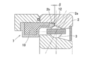
- the rolling bearing described in Patent Document 1 is opposed to the stepped surface 2 b of the fixed-side raceway ring 2 (for example, the outer ring) via a gap 12, and the internal grease reservoir 10 and the gap 12 are separated from each other.
- An annular grease reservoir forming component 7 is provided, and the base oil in the grease is supplied from the gap 12 to the raceway surface 2a of the fixed-side raceway ring 2 due to a temperature difference during operation.
- the base oil of the grease moves to the gap 12 due to the thickener in the grease and the capillary phenomenon of the gap 12, and when the bearing is operated, the base oil stored in the gap 12 is It is discharged from the gap 12 due to the temperature change of the fixed-side raceway 2 generated and the air flow generated by the revolution and rotation of the rolling element 3.
- the discharged base oil moves while adhering to the raceway surface 2a of the fixed-side raceway ring 2 and is continuously supplied to the rolling element contact portion.
- the base oil in the grease can be effectively discharged and stably supplied as the lubricating oil for the bearing, leading to an extension of the bearing life.
- the gap amount ⁇ is preferably 0.05 to 0.1 mm.
- the object of the present invention is to lubricate the raceway surface by using the grease sealed in the bearing and the grease sealed in the grease reservoir provided in the bearing, and continuously stabilize the base oil of the grease sealed in the grease reservoir.
- a rolling bearing device capable of achieving high speed, long life, and maintenance-free by supplying to the raceway surface of the stationary side raceway is provided.
- a rolling bearing device is a rolling bearing device having an inner ring, an outer ring, and a plurality of rolling elements interposed between the raceway surfaces of the inner and outer rings.
- a stepped surface following the raceway surface is provided on the side raceway in a direction away from the rolling element, and a spacer is provided adjacent to the stationary side raceway in a direction in which the stepped surface faces.
- An annular grease reservoir forming part that is fitted to the peripheral surface and has a grease reservoir formed therein is provided.
- the grease reservoir forming component includes a main body portion that fits into the spacer, and the stepped surface from the main body portion.
- a hollow gap forming piece that extends along a bearing space side peripheral surface of the fixed-side raceway and has a tip surface facing the step surface.
- a gap between a portion of the end surface where the convex portion does not exist and the stepped surface is an oil passage that communicates with the grease reservoir and guides the base oil of grease to the raceway surface of the stationary side raceway, and the gap is formed.
- a surface is formed, and the end surface of the spacer comes into contact with the step surface, and the end surface of the spacer and the step surface of the stationary side race ring sandwich the race ring side annular wall portion.
- the fixed-side raceway can be an outer race.
- the rolling bearing device of this configuration is used by filling the grease reservoir with grease.
- a temperature change occurs due to a heat cycle in the grease reservoir accompanying the operation and stop of the rolling bearing device, and the base oil separated from the grease is supplied to the raceway surface of the fixed-side raceway through the gap.
- the base oil separated from the grease is supplied to the raceway surface of the fixed-side raceway through the gap.
- the grease pool forming component is assembled so that the raceway-side annular wall portion of the gap forming piece is sandwiched between the end face of the spacer and the stepped surface of the fixed-side raceway. Thereby, the front-end
- the grease base oil sealed in the grease reservoir can be continuously and stably supplied to the raceway surface of the stationary raceway. Since the grease reservoir forming part is an independent and integral part, the grease can be sealed in a sealed state before assembly. Therefore, it is possible to prevent leakage of grease or its base oil at the time of assembly and entry of foreign matters such as dust. Also, the assemblability is good.
- the non-race ring side annular wall portion that is not the race ring side annular wall portion is more than the race ring side annular wall portion. It is preferable that the front end protrudes toward the step surface and the convex portion is provided on the front end surface of the non-orbital ring-side annular wall. With this configuration, the tip of the convex portion provided on the tip surface of the gap forming piece can be reliably brought into contact with the step surface.
- an annular notch is provided in the tip surface of the race ring-side annular wall portion, and a gap between the tip surface of the race ring-side annular wall portion and the step surface is closed in this notch.
- An oil leakage prevention body made of an elastic body may be fitted and provided. If it is the said structure, base oil may leak out of a bearing from the clearance gap between the front end surface and level
- the oil leakage prevention body By making the oil leakage prevention body an elastic body, the oil leakage prevention body is in close contact with the step surface when the raceway ring-side annular wall is sandwiched between the end face of the spacer and the step surface of the stationary raceway. The oil leakage prevention effect is enhanced.
- the bearing ring side annular wall portion of the gap forming piece when the bearing ring side annular wall portion of the gap forming piece is fitted to the bearing space side peripheral surface of the fixed side race ring, the fixed side race ring side peripheral surface of the race ring side annular wall portion It is preferable to provide an annular groove in the middle portion of this, and to insert an oil leakage prevention body made of an elastic body into this groove.
- an annular groove may be provided in an intermediate portion of the peripheral surface on the bearing space side of the fixed-side bearing ring, and an oil leakage prevention body made of an elastic body may be fitted into the groove.
- the base oil may leak out of the bearing from the contact portion between the two.
- the oil leakage prevention body as described above, it is possible to prevent the base oil from leaking from the contact portion between the race ring side annular wall portion and the fixed side race ring.
- the grease reservoir forming component A stopper that prevents the spacer from coming off from the main body may be provided. If the stopper is provided, the grease reservoir forming component and the spacer can be handled in an integrated manner, and the handleability during assembly is good.
- the rolling bearing device according to the present invention can be suitably used for supporting a machine tool spindle because the above-described effects can be obtained.
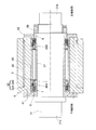
- FIG. 3 is a cross-sectional view of a spindle device using the rolling bearing device shown in FIGS. 1 (A), 1 (B) and 2. It is sectional drawing of the conventional rolling bearing with a lubrication mechanism.
- this rolling bearing device includes a rolling bearing A having a plurality of rolling elements 3 interposed between raceway surfaces 1a and 2a of an inner ring 1, an outer ring 2, and inner and outer rings 1 and 2.
- the outer ring positioning spacer 6 and the grease reservoir forming part 7 are provided.
- the plurality of rolling elements 3 are held by a cage 4, and one end of the bearing space between the inner and outer rings 1 and 2 is sealed with a seal 5.
- the rolling bearing A is an angular ball bearing, the outer ring positioning spacer 6 and the grease reservoir forming component 7 are provided on the front side of the bearing, and the seal 5 is provided on the end on the back side of the bearing.
- the grease reservoir forming component 7 also serves as a seal on the front side of the bearing, thereby preventing leakage of grease from the front side of the bearing.
- a portion indicated by crossed hatching indicates a portion filled with grease.
- the inner ring 1 is fitted to a main shaft (not shown) so as to be rotatable, and the outer ring 2 is fixedly supported in a fitted state on the inner periphery of a housing (not shown) in the main shaft device.
- a step surface 2b following the raceway surface 2a follows the outer ring front side away from the rolling elements 3, that is, the edge on the opposite side to the direction in which the contact angle occurs on the raceway surface 2a.
- the step surface 2b is a surface that extends from the raceway surface 2a to the outer diameter side and faces the outer ring front side.
- An inner peripheral surface portion 2c continuing from the step surface 2b to the outer ring front side is a cylindrical surface.
- the shoulder 1b on the front side of the inner ring 1 is shaped to recede from the front side end surfaces of the inner and outer rings 1 and 2 in order to avoid interference with the body part 7a of the grease pool forming component 7 described later.
- the outer ring positioning spacer 6 is provided in contact with the front end face of the outer ring 2.
- the end surfaces 2d and 6a that are the mating surfaces of the outer ring 2 and the outer ring positioning spacer 6 are both the same diameter at the outer diameter edge, and the outer ring positioning spacer 6 is smaller in diameter than the outer ring 2 at the inner diameter edge.
- An inner ring positioning spacer 8 is provided on the front side of the inner ring 1 in contact with the width surface.
- the grease reservoir forming component 7 is an annular component, and a main body portion 7a having a grease reservoir 10 formed therein, and a flow path extending from the main body portion 7a toward the stepped surface 2b and communicating with the grease reservoir 10 therein.
- 11 is formed with a hollow gap forming piece 7b.
- the front end of the channel 11 is the smallest width portion 11a having the smallest radial width.
- the main body portion 7 a is fitted to the inner circumference of the outer ring positioning spacer 6, and the gap forming piece 7 b is fitted to the inner circumferential surface portion 2 c of the outer ring 2.
- the grease reservoir forming component 7 can be an integral part, but may be configured by joining an inner diameter side member and an outer diameter side member.
- the outer peripheral surface 9 of the grease reservoir forming component 7 includes a race ring fitting surface 9a that fits to the inner peripheral surface portion 2c of the outer ring 2 and a spacer fitting surface 9b that fits to the inner peripheral surface of the outer ring positioning spacer 6. And a step surface 9c formed at the boundary between the bearing ring fitting surface 9a and the spacer fitting surface 9b.
- the bearing ring fitting surface 9a corresponds to the outer periphery of the gap forming piece 7b
- the spacer fitting surface 9b corresponds to the outer periphery of the main body portion 7a.
- the step surface 9c is formed at the base end of the race ring-side annular wall portion 7bb of the inner and outer annular wall portions 7ba, 7bb constituting the gap forming piece 7b, and has a step in the outer diameter direction with respect to the main body portion 7a. It is a surface that has.
- the step surface 9c contacts the mating surface 6a which is the end surface of the outer ring positioning spacer 6, whereby the axial position of the grease reservoir forming component 7 is positioned.
- the gap forming piece 7b is sandwiched between the end surface 6a of the spacer 6 and the step surface 2b of the outer ring 2.
- an oil discharge gap 12 is formed between the step surface 2b of the outer ring 2 and the tip surface 13 of the gap forming piece 7b. Facing the gap 12, the minimum width portion 11a of the flow path 11 is opened.
- the tip end of the non-race ring side annular wall portion 7ba is protruded toward the step surface 2b side than the race ring side annular wall portion 7bb. It is. In other words, of the front end surface 13 of the gap forming piece 7b, the front end surface 13a of the non-race ring side annular wall portion 7ba is closer to the step surface 2b than the front end surface 13b of the race ring side annular wall portion 7bb. Yes. And the convex part 14 which the front-end
- the oil discharge gap 12 is substantially between the portion where the convex portion 14 of the tip surface 13a does not exist and the step surface 2b.
- the protruding amount of the convex portion 14 is set so that the gap amount ⁇ of the gap 12 is, for example, 0.05 to 0.1 mm.
- the outer peripheral surface raceway fitting surface 9a of the grease reservoir forming component 7 is fitted to the inner peripheral surface portion 2c of the outer ring 2, and the outer peripheral surface spacer fitting surface of the grease reservoir forming component 7 is fitted.
- the outer ring positioning spacer 6 is fitted to 9b.
- the end surface 6 a of the outer ring positioning spacer 6 is brought into contact with the step surface 9 c of the grease reservoir forming component 7, and the gap forming piece 7 b is sandwiched between the end surface 6 a of the spacer 6 and the step surface 2 b of the outer ring 2.
- the convex portion 14 of the gap forming piece 7b comes into contact with the step surface 2b of the outer ring 2, and a gap of a predetermined gap amount ⁇ is formed between the tip surface 13 of the gap forming piece 7b and the step surface 2b of the outer ring 2. 12 is formed. Since the grease reservoir forming part 7 is an independent and integral part, the grease can be sealed in a sealed state before assembly. Therefore, it is possible to prevent leakage of grease or its base oil at the time of assembly and entry of foreign matters such as dust. Also, the assemblability is good.
- a base oil discharge action by the capillary phenomenon shown below is also added. That is, when the bearing is stopped, the grease base oil moves from the flow path 11 to the gap 12 due to the thickener in the grease and the capillary phenomenon of the gap 12, and the capillary phenomenon and the surface tension of the oil combine to form the gap 12.
- the base oil is kept oily.
- the bearing When the bearing is operated, the base oil stored in the clearance 12 flows out of the clearance 12 due to the temperature rise of the outer ring 2 generated by the operation and the air flow generated by the revolution and rotation of the rolling element 3, and the race of the outer ring 2. It moves while adhering to the surface 2a and is continuously supplied to the rolling element contact portion.
- the base oil separated from the grease is supplied to the raceway surface 2a of the outer ring 2 through the gap 12 due to the temperature fluctuation due to the heat cycle in the grease reservoir 10 accompanying the repeated operation stop and operation restart. Therefore, the lubricating oil is reliably supplied.
- the base oil is discharged to the raceway surface 2a of the outer ring 2 also by the capillary phenomenon in the gap 12, the lubrication is further ensured. As a result, using only the grease sealed in the bearing, it is possible to increase the speed, extend the service life, eliminate maintenance, and supply a stable lubricant.
- the fixed-side raceway is the outer ring 2
- the stepped surface 2b is provided on the outer ring 2
- the sealed grease is applied to the inner diameter of the outer ring by centrifugal force.
- the base oil is reliably connected between the gap 12 and the raceway surface 2a.
- the base oil that is consumed as the lubricating oil in the rolling element contact portion is replenished to the raceway surface 2a from the grease reservoir 10 via the gap 12, and the lubricating oil is more stably replenished.
- the rolling bearing is an angular ball bearing
- the stepped surface 2b is formed following the edge on the side opposite to the direction in which the contact angle occurs on the raceway surface 2a.
- step difference surface 2b can be closely approached to the center vicinity of the rolling element 3, and the replenishment of the lubricating oil from the clearance gap 12 to the track surface 2a can be performed more efficiently.
- FIG. 3 shows a different embodiment of the present invention. This embodiment is different from the above-described embodiment in that an annular notch 15 is provided in the tip surface 13b of the race ring-side annular wall portion 7bb of the gap forming piece 7b, and the race ring-side annular wall portion is provided in the notch 15.
- the sheet-like oil leakage prevention body 16 made of an elastic body such as rubber that closes the gap between the front end surface 13b of the 7bb and the stepped surface 2b is fitted, and the race-ring-side annular wall portion of the gap forming piece 7b
- An annular groove 17 is provided in an intermediate portion of the outer peripheral surface raceway fitting surface 9a which is an outer peripheral surface of 7bb, and an oil leakage prevention body 18 made of an elastic body is fitted in the groove 17.
- the oil leakage prevention body 18 is an O-ring.
- the race ring-side annular wall portion 7bb of the gap forming piece 7b is fitted to the outer ring 2
- the race ring-side annular wall portion 7bb and the outer ring 2 are fitted in a loose fit in order to improve assemblability. Is done. In that case, the base oil may leak out of the bearing from the contact portion between the two.
- the oil leakage prevention bodies 16 and 18 as described above, it is possible to prevent the base oil from leaking from the contact portion between the grease reservoir forming component 7 and the outer ring 2.
- the oil leakage prevention body 16 has the oil leakage prevention body 18 in close contact with the step surface 2b when the raceway ring-side annular wall portion 7bb is sandwiched between the end surface 6a of the outer ring positioning spacer 6 and the step surface 2b of the outer ring 2.
- the oil leakage prevention effect from the gap is enhanced. Only one of the oil leakage prevention bodies 16 and 18 may be provided.
- annular groove 19 is provided in an inner peripheral surface portion 2 c that is a peripheral surface on the bearing space side of the outer ring 2, and an oil leakage prevention body 18 such as an O-ring is fitted in the groove 19. Similarly, the base oil can be prevented from leaking from the contact portion between the race-ring-side annular wall portion 7bb and the outer ring 2.
- FIG. 5 shows a further different embodiment.
- This embodiment is different from the embodiments of FIGS. 1A, 1B, and 2 in that the central portion in the axial direction of the inner peripheral surface of the outer ring positioning spacer 6 is a cylindrical surface having a smaller inner diameter than the other.
- a step portion 6c perpendicular to the axial direction is formed at the bearing front side end of the guide portion 6b.
- a stopper 21 that slightly rises to the outer diameter side is provided near the bearing front side end of the outer peripheral face spacer fitting surface 9b of the grease reservoir forming component 7.
- the retainer 21 has a shape in which the bearing rear side end is formed on a surface perpendicular to the axial direction, and the bulging amount gradually decreases toward the bearing front side.
- the outer ring positioning spacer 6 can be slid from the bearing front side and fitted to the grease reservoir forming component 7.
- the surface of the bearing back side end of the retainer 21 is engaged with the inner peripheral surface step portion 6 c of the outer ring positioning spacer 6, thereby preventing the outer ring positioning spacer 6 from slipping out of the grease pool forming component 7. Therefore, the assembly can be performed in a state where the grease reservoir forming component 7 and the outer ring positioning spacer 6 are integrated in advance, and the assembling work is easy.
- FIGS. 6A, 6B and 7 show a rolling bearing as a reference example.
- this rolling bearing includes an inner ring 1, an outer ring 2, a plurality of rolling elements 3, an outer ring positioning spacer 6, and a grease reservoir forming component 7, like the rolling bearing.
- Each of the rolling bearings has a grease reservoir 10 formed inside a single grease reservoir forming component 7, whereas this rolling bearing has a grease reservoir between the grease reservoir forming component 7 and the outer ring positioning spacer 6. The difference is that 10 is formed.
- the differences in configuration other than the above are listed below. Parts having the same configuration are denoted by the same reference numerals in the drawings, and description thereof is omitted.
- the outer ring 2 serving as a fixed-side raceway has a shape cut off at the front end of the raceway surface 2a, and the step surface 2b following the raceway surface 2a and the end face 2d with the outer ring positioning spacer 6 are flush with each other. .
- the step surface 2b is representatively shown.
- the outer ring positioning spacer 6 is provided with a flange-shaped side wall portion 6b that is in contact with the stepped surface 2b of the outer ring 2 at the end surface 6a on the back side and extends toward the inner diameter side at the front side end.
- the inner peripheral surface excluding the side wall portion 6b is cylindrical.
- the grease reservoir forming component 7 is an annular component arranged on the inner peripheral side of the outer ring positioning spacer 6, and the body portion 7 a that forms the grease reservoir 10 between the outer ring positioning spacer 6 and the outer ring positioning spacer 6.
- a gap forming piece 7b that forms a flow path 11 communicating with the grease reservoir 10 with the seat 6 is formed.
- the front end of the channel 11 is the smallest width portion 11a having the smallest radial width.
- the main body portion 7a is located substantially outside the end face on the bearing front side of the inner ring 1, and the gap forming piece 7b is located substantially inside the end face.
- the tip surface 13 of the gap forming piece 7b facing the step surface 2b is provided with convex portions 14 whose tips are in contact with the step surface 2b in the assembled state at a plurality of locations in the circumferential direction (FIG. 7). Therefore, the gap between the portion of the tip surface 13 where the convex portion 14 does not exist and the step surface 2b is substantially the oil discharge gap 12.
- the protruding amount of the convex portion 14 is set so that the gap amount ⁇ of the gap 12 is, for example, 0.05 to 0.1 mm.
- the side wall portion 7aa of the grease pool forming component main body portion 7a faces the bearing back side of the side wall portion 6b of the outer ring positioning spacer 6 and is provided at a plurality of locations in the circumferential direction of the grease pool forming component main body portion side wall portion 7aa.
- the grease reservoir forming component 7 is pressed to the outer ring 2 side by a spring 24 interposed between the bottom of the recess 23 and the outer ring positioning spacer side wall 6b. Therefore, the convex portion 14 is always in contact with the step surface 2b of the outer ring 2, and the gap amount ⁇ of the gap 12 can be kept constant.
- the spring 24 is a biasing means that biases the grease pool forming component 7 in a direction in which the convex portion 14 is pressed against the outer ring step surface 2b.
- This rolling bearing is also assembled in a state where the grease reservoir 10 and the flow path 11 are filled with grease, and grease is sealed for initial lubrication in the bearing, so that the same effect as the rolling bearing can be obtained.
- an O-ring 25 is provided between the grease reservoir forming component main body side wall portion 7aa and the outer ring positioning spacer side wall portion 6b.
- the grease pool forming component 7 can be urged in the direction in which the convex portion 14 is pressed against the outer ring step surface 2b by interposing the urging means comprising
- the urging means is the O-ring 25
- oil can be prevented from leaking from the contact portion between the grease reservoir forming component 7 and the outer ring positioning spacer 6.
- an annular groove 26 is provided in the end face 6 a of the outer ring positioning spacer 6 and an oil leakage prevention body 18 such as an O-ring is fitted into the groove 26, the oil is removed from the contact portion between the outer ring 2 and the outer ring positioning spacer 6. Prevents leakage.
- the outer peripheral surface of the side wall portion 7aa of the grease reservoir forming component main body portion 7a is arranged on the outer peripheral surface. If a similar retaining member 21 is provided and a step portion 6c that engages with the retaining member 21 is provided on the inner peripheral surface of the outer ring positioning spacer 6, the grease reservoir forming component 7 and the outer ring positioning spacer 6 are integrated in advance. Assembling can be performed in a state of being assembled, and assembling work is easy.
- FIG. 9 shows an example of a spindle device for a machine tool using the rolling bearing device shown in FIGS. 1 (A), (B) and FIG.
- This main shaft device uses two rolling bearing devices 30A and 30B in combination on the back surface, and supports both ends of the main shaft 31 rotatably by these rolling bearing devices 30A and 30B.
- the inner ring 1 of each of the rolling bearing devices 30 ⁇ / b> A and 30 ⁇ / b> B is positioned by the inner ring positioning spacer 8 and the inner ring spacer 37, and is fastened and fixed to the main shaft 31 by an inner ring fixing nut 39.
- the outer ring 2 is positioned and fixed in the housing 32 by an outer ring positioning spacer 6, an outer ring spacer 40, and outer ring pressing lids 41 and 42.
- the housing 32 is formed by fitting a housing inner cylinder 32A and a housing outer cylinder 32B, and an oil passage groove 43 for cooling is provided in the fitting portion.
- the spindle 31 is provided with a chuck (not shown) for detachably attaching a tool or a workpiece (not shown) to the lower end 31a, and the upper end 31b is driven by a rotation transmission mechanism (not shown) such as a motor. ).
- the motor may be built in the housing 32.
- This spindle device can be applied to various machine tools such as a machining center, a lathe, a milling machine, and a grinding machine.
- the speed of the rolling bearings 30A and 30B is increased, the service life is increased, and the maintenance is made free by appropriately adjusting the amount of the lubricating oil discharged from the gap 12 between the rolling bearings 30A and 30B. Is effectively demonstrated.
- Inner ring 1a Raceway surface 2 Outer ring (fixed side raceway) 2a raceway surface 2b stepped surface 3 rolling element 6 outer ring positioning spacer 7 grease reservoir forming component 7a main body 7b gap forming pieces 7ba, 7bb annular wall portion 9 outer peripheral surface 9a raceway ring fitting surface 9b spacer fitting surface 9c stepped surface DESCRIPTION OF SYMBOLS 10 Grease pool 11 Flow path 12 Crevice 13 Front end surface 14 Convex part 15 Notch 16, 18 Oil leak prevention body 17, 19, 25 Groove 21 Retaining prevention 24 Spring (biasing means) 25 O-ring (biasing means) 30A, 30B Rolling bearing 31 Spindle
Landscapes
- Engineering & Computer Science (AREA)
- General Engineering & Computer Science (AREA)
- Mechanical Engineering (AREA)
- Rolling Contact Bearings (AREA)
Abstract
グリース溜まりに封入したグリースの基油を継続的に安定して固定側軌道輪の軌道面に供給することにより、高速化と長寿命化、メンテナンスフリーを達成できる転がり軸受装置を提供する。内輪(1)、外輪(2)、および転動体(3)を有する。例えば、固定側軌道輪が外輪(2)とする。外輪(2)に隣接して間座(6)を設ける。この間座(6)の内周に、内部にグリース溜まり(10)が形成された環状のグリース溜まり形成部品(7)を設ける。グリース溜まり形成部品(7)の隙間形成片(7b)の先端面(13)に、先端が段差面(2b)に当接する凸部(14)を設け、凸部(14)が存在しない先端面(13)の箇所と段差面(2b)との間の隙間(12)を、グリース溜まり(10)のグリースの基油を外輪軌道面(2a)へ導く油路とする。間座(6)の端面と段差面(2b)とで隙間形成片(7b)を挟み込む。
Description
本願は2008年7月8日出願の特願2008-177485の優先権を主張するものであり、その全体を参照により本出願の一部をなすものとして引用する。
この発明は、工作機械主軸等のグリース潤滑とされる潤滑機構付きの転がり軸受装置に関する。
工作機械主軸軸受の潤滑方法として、メンテナンスフリーで使用可能なグリース潤滑、搬送エアに潤滑オイルを混合してオイルをノズルより軸受内に噴射するエアオイル潤滑、軸受内に潤滑油を直接に噴射するジェット潤滑等の方法がある。最近の工作機械は、加工能率を上げるために、ますます高速化の傾向にあり、主軸軸受の潤滑も比較的安価で簡単に高速化が可能なエアオイル潤滑が多く用いられてきている。しかし、このエアオイル潤滑法は、付帯設備としてエアオイル供給装置が必要であることと、多量のエアを必要とすることから、コスト、騒音、省エネ、省資源の観点から問題がある。また、オイルの飛散によって環境を悪化させる問題もある。これらの問題を回避するために、最近ではグリース潤滑による高速化が注目され始め、要望も多くなってきている。
このような試みの一つに、例えば特許文献1が挙げられる。特許文献1に記載の転がり軸受は、図10に示すように、固定側軌道輪2(例えば外輪)の段差面2bと隙間12を介して対向し、内部のグリース溜まり10と前記隙間12とが連通した環状のグリース溜まり形成部品7を設け、グリース中の基油を、運転時の温度差により前記隙間12から固定側軌道輪2の軌道面2aに供給するようにしたものである。
詳しくは、軸受の停止時には、グリース中の増稠剤および隙間12の毛細管現象によりグリースの基油が隙間12に移動し、軸受を運転すると、隙間12に貯油されていた基油は、運転で生じる固定側軌道輪2の温度変化と、転動体3の公転・自転で生じる空気流とにより隙間12から吐出される。吐出された基油は、固定側軌道輪2の軌道面2aに付着しながら移動して転動体接触部に連続的に補給される。
詳しくは、軸受の停止時には、グリース中の増稠剤および隙間12の毛細管現象によりグリースの基油が隙間12に移動し、軸受を運転すると、隙間12に貯油されていた基油は、運転で生じる固定側軌道輪2の温度変化と、転動体3の公転・自転で生じる空気流とにより隙間12から吐出される。吐出された基油は、固定側軌道輪2の軌道面2aに付着しながら移動して転動体接触部に連続的に補給される。
この種の潤滑機構付きの転がり軸受では、グリース中の基油を効果的に吐出させて、軸受の潤滑油として安定して供給することが軸受寿命の延長につながる。継続的に安定した量の基油を吐出させるには、隙間12の隙間量δを適正範囲内に管理することが重要である。例えば、隙間量δは0.05~0.1mmが良いとされている。しかし、部品の寸法誤差や組立誤差等により、隙間量δを適正に管理するのが難しかった。
この発明の目的は、軸受内に封入したグリースと軸受に設けたグリース溜まりに封入したグリースとを使用して軌道面の潤滑を行え、さらにグリース溜まりに封入したグリースの基油を継続的に安定して固定側軌道輪の軌道面に供給することにより、高速化と長寿命化、メンテナンスフリーを達成できる転がり軸受装置を提供することである。
この発明にかかる転がり軸受装置は、内輪、外輪、およびこれら内外輪の軌道面間に介在する複数の転動体を有する転がり軸受装置であって、軌道輪である内輪および外輪のうち、回転しない固定側軌道輪に、軌道面に続く段差面を転動体から離れる方向に設け、前記固定側軌道輪に対し、前記段差面が向く方向に隣接して間座を設け、この間座の軸受空間側の周面に嵌合して、内部にグリース溜まりが形成された環状のグリース溜まり形成部品を設け、このグリース溜まり形成部品は、前記間座に嵌合する本体部と、この本体部から前記段差面側へ前記固定側軌道輪の軸受空間側の周面に沿って延びて先端面が前記段差面に対向する中空の隙間形成片とを有し、この隙間形成片の先端面に、先端が前記段差面に当接する凸部を設け、この先端面の前記凸部が存在しない箇所と前記段差面との間の隙間が、前記グリース溜まりと連通してグリースの基油を前記固定側軌道輪の軌道面へ導く油路となり、かつ前記隙間形成片を構成する内外の環状壁部のうち、前記固定側軌道輪の軸受空間側の周面に沿う軌道輪側環状壁部の基端に、前記本体部に対して径方向の段差を有する段面が形成され、この段面に前記間座の端面が当接してこの間座の端面と前記固定側軌道輪の段差面とで前記軌道輪側環状壁部を挟み込んでいる。例えば、前記固定側軌道輪を外輪とすることができる。
この構成の転がり軸受装置は、グリース溜まりにグリースを充填して使用される。転がり軸受装置の運転と停止に伴うグリース溜まりでのヒートサイクルによる温度変化が発生し、グリースから分離した基油が隙間を通って固定側軌道輪の軌道面に供給される。これにより、軸受内に封入したグリースだけを使用して高速化と長寿命化、メンテナンスフリーを達成できる。
間座の端面と固定側軌道輪の段差面とで隙間形成片の軌道輪側環状壁部を挟み込む状態に、グリース溜まり形成部品を組み込む。これにより、凸部の先端が段差面に当接する状態に維持することができる。隙間形成片の先端面における凸部が存在しない箇所と固定側軌道輪の段差面との間に隙間が形成されているため、凸部の軸方向長さを目標とする隙間量に設定しておくことで、目標隙間量の隙間が得られる。これにより、グリース溜まりに封入したグリースの基油を継続的に安定して固定側軌道輪の軌道面に供給することができる。
グリース溜まり形成部品は独立した一体型の部品であるため、組立前にグリースを密封状態に封入しておくことができる。そのため、組立時におけるグリースまたはその基油の漏れ、およびゴミ等の異物の混入を防げる。また、組立性も良い。
グリース溜まり形成部品は独立した一体型の部品であるため、組立前にグリースを密封状態に封入しておくことができる。そのため、組立時におけるグリースまたはその基油の漏れ、およびゴミ等の異物の混入を防げる。また、組立性も良い。
この発明において、前記隙間形成片を構成する内外の環状壁部を比較して、前記軌道輪側環状壁部ではない非軌道輪側環状壁部の方を前記軌道輪側環状壁部よりも、先端を前記段差面側へ突出させ、前記非軌道輪側環状壁部の先端面に前記凸部を設けるのが良い。
この構成とすれば、隙間形成片の先端面に設けた凸部の先端を確実に段差面に当接させることができる。
この構成とすれば、隙間形成片の先端面に設けた凸部の先端を確実に段差面に当接させることができる。
上記構成とした場合、前記軌道輪側環状壁部の先端面に環状の切欠きを設け、この切欠きに、前記軌道輪側環状壁部の先端面と前記段差面との間の隙間を塞ぐ弾性体からなる油漏れ防止体を嵌め込んで設けるのが良い。
前記構成であると、軌道輪側環状壁部の先端面と段差面との間の隙間から基油が軸受外へ漏れる可能性がある。そこで、前記隙間を油漏れ防止体で塞ぐことで、油漏れを防止できる。油漏れ防止体を弾性体とすることにより、間座の端面と固定側軌道輪の段差面とで軌道輪側環状壁部を挟み込んだときに、油漏れ防止体が段差面に密着した状態となり、油漏れ防止効果が高まる。
前記構成であると、軌道輪側環状壁部の先端面と段差面との間の隙間から基油が軸受外へ漏れる可能性がある。そこで、前記隙間を油漏れ防止体で塞ぐことで、油漏れを防止できる。油漏れ防止体を弾性体とすることにより、間座の端面と固定側軌道輪の段差面とで軌道輪側環状壁部を挟み込んだときに、油漏れ防止体が段差面に密着した状態となり、油漏れ防止効果が高まる。
この発明において、前記隙間形成片の軌道輪側環状壁部が前記固定側軌道輪の軸受空間側の周面に嵌合する場合、前記軌道輪側環状壁部における固定側軌道輪側の周面の中間部に環状の溝を設け、この溝に弾性体からなる油漏れ防止体を嵌め込んで設けるのが良い。または、前記固定側軌道輪の軸受空間側の周面の中間部に環状の溝を設け、この溝に弾性体からなる油漏れ防止体を嵌め込んで設けても良い。
軌道輪側環状壁部が固定側軌道輪の軸受空間側の周面に嵌合する場合、組立性を良くするために、軌道輪側環状壁部と固定側軌道輪とをルーズフィットで嵌合させることがある。その場合、両者の接触部から基油が軸受外に漏れる可能性がある。上記のように油漏れ防止体を設けることで、軌道輪側環状壁部と固定側軌道輪の接触部から基油が漏れるのを防げる。
軌道輪側環状壁部が固定側軌道輪の軸受空間側の周面に嵌合する場合、組立性を良くするために、軌道輪側環状壁部と固定側軌道輪とをルーズフィットで嵌合させることがある。その場合、両者の接触部から基油が軸受外に漏れる可能性がある。上記のように油漏れ防止体を設けることで、軌道輪側環状壁部と固定側軌道輪の接触部から基油が漏れるのを防げる。
この発明において、前記グリース溜まり形成部品本体部の前記間座に対する嵌合面に、前記間座の軸受空間側の周面に前記グリース溜まり形成部品本体部が嵌合した状態で、グリース溜まり形成部品本体部に対して間座が抜けるのを防ぐ抜け止めを設けても良い。
抜け止めが設けられていれば、グリース溜まり形成部品と間座とを一体化して取り扱うことができ、組立時の取扱性が良い。
抜け止めが設けられていれば、グリース溜まり形成部品と間座とを一体化して取り扱うことができ、組立時の取扱性が良い。
この発明の転がり軸受装置は、上記作用効果が得られるため、工作機械主軸の支持に好適に用いることができる。
この発明は、添付の図面を参考にした以下の好適な実施形態の説明からより明瞭に理解されるであろう。しかしながら、実施形態および図面は単なる図示および説明のためのものであり、この発明の範囲を定めるために利用されるべきでない。この発明の範囲は添付のクレームによって定まる。添付図面において、複数の図面における同一の部品番号は、同一部分を示す。
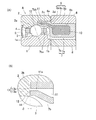
(A)はこの発明の実施形態に係る転がり軸受装置の断面図、(B)はその部分拡大図である。
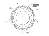
同転がり軸受装置のグリース溜まり形成部品の側面図である。
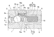
この発明の異なる実施形態に係る転がり軸受装置の断面図である。
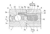
この発明のさらに異なる実施形態に係る転がり軸受装置の断面図である。
この発明のさらに異なる実施形態に係る転がり軸受装置の断面図である。
(A)は参考例としての転がり軸受装置の断面図、(B)はその部分拡大図である。
同転がり軸受装置のグリース溜まり形成部品の側面図である。
異なる参考例としての転がり軸受装置の断面図である。
図1(A),(B)および図2に示す転がり軸受装置を用いた主軸装置の断面図である。
従来の潤滑機構付きの転がり軸受の断面図である。
この発明の実施形態を図1(A),(B)および図2と共に説明する。図1(A),(B)において、この転がり軸受装置は、内輪1、外輪2、および内外輪1,2の軌道面1a,2a間に介在する複数の転動体3を有する転がり軸受Aと、外輪位置決め間座6と、グリース溜まり形成部品7とを備える。複数の転動体3は、保持器4に保持され、内外輪1,2間の軸受空間の一端は、シール5によって密封されている。転がり軸受Aはアンギュラ玉軸受であり、外輪位置決め間座6およびグリース溜まり形成部品7は軸受正面側に設けられ、シール5は軸受背面側の端部に設けられる。軸受正面側ではグリース溜まり形成部品7がシールを兼ねており、軸受正面側からのグリースの漏れが防止される。図1(A)において、交差したハッチングで示す部分は、グリースの充填された部分を示す。内輪1は、図示しない主軸に嵌合して回転可能とされ、外輪2は主軸装置における図示しないハウジングの内周に嵌合状態で固定支持される。
固定側軌道輪となる外輪2には、その軌道面2aに続く段差面2bが、転動体3から離れる外輪正面側、つまり軌道面2aにおける接触角が生じる方向と反対側の縁部に続いて設けられている。この段差面2bは、軌道面2aから外径側に延びて外輪正面側に対面する面である。段差面2bから外輪正面側に続く内周面部分2cは、円筒状の面とされている。
内輪1の正面側の肩部1bは、後記グリース溜まり形成部品7の本体部7aとの干渉を避けるために、内外輪1,2の正面側端面よりも後退した形状としてある。
内輪1の正面側の肩部1bは、後記グリース溜まり形成部品7の本体部7aとの干渉を避けるために、内外輪1,2の正面側端面よりも後退した形状としてある。
外輪位置決め間座6は、外輪2の正面側の端面に接して設けられる。外輪2および外輪位置決め間座6の合わせ面となるそれぞれの端面2d,6aは、外径縁では両者共に同径で、内径縁では外輪2よりも外輪位置決め間座6の方が小径である。なお、内輪1の正面側には、幅面に接して内輪位置決め間座8が設けられている。
グリース溜まり形成部品7は環状の部品であり、内部にグリース溜まり10が形成された本体部7aと、この本体部7aから前記段差面2b側へ延び、内部に前記グリース溜まり10に連通する流路11が形成された中空の隙間形成片7bとでなる。流路11は、その先端部が径方向幅の最も小さい最小幅部11aになっている。本体部7aは外輪位置決め間座6の内周に嵌合し、隙間形成片7bは外輪2の前記内周面部分2cに嵌合している。グリース溜まり形成部品7は一体物とすることもできるが、内径側の部材と外径側の部材を接合した構成してもよい。
グリース溜まり形成部品7の外周面9は、外輪2の内周面部分2cに嵌合する軌道輪嵌合面9aと、外輪位置決め間座6の内周面に嵌合する間座嵌合面9bと、これら軌道輪嵌合面9aと間座嵌合面9bとの境界に形成された段面9cとでなる。軌道輪嵌合面9aは隙間形成片7bの外周に相当し、間座嵌合面9bは本体部7aの外周に相当する。段面9cは、隙間形成片7bを構成する内外の環状壁部7ba,7bbのうちの軌道輪側環状壁部7bbの基端に形成され、前記本体部7aに対して外径方向の段差を有する面である。
組立状態では、段面9cが外輪位置決め間座6の端面である合わせ面6aに当接することにより、グリース溜まり形成部品7の軸方向位置が位置決めされる。言い換えると、間座6の端面6aと外輪2の段差面2bとで、隙間形成片7bを挟み込んだ状態になる。この組立状態では、外輪2の段差面2bと隙間形成片7bの先端面13との間に、油吐出用の隙間12が形成される。この隙間12に面して、前記流路11の最小幅部11aが開口している。
隙間形成片7bを構成する内外の環状壁部7ba,7bbを比較して、非軌道輪側環状壁部7baの方が軌道輪側環状壁部7bbよりも、先端を段差面2b側へ突出させてある。言い換えると、隙間形成片7bの先端面13のうち、非軌道輪側環状壁部7baの先端面13aの方が軌道輪側環状壁部7bbの先端面13bよりも、段差面2bに接近している。そして、非軌道輪側環状壁部7baの先端面13aの周方向複数箇所(図2)に、組立状態において先端が段差面2bに当接した凸部14が設けられている。つまり、先端面13aの凸部14が存在しない箇所と段差面2bとの間が、実質上の前記油吐出用隙間12になっている。凸部14の突出量は、隙間12の隙間量δが例えば0.05~0.1mmになるように設定されている。
この転がり軸受装置の組立に際し、グリース溜まり形成部品7の外周面軌道輪嵌合面9aを外輪2の内周面部分2cに嵌合させ、かつグリース溜まり形成部品7の外周面間座嵌合面9bに外輪位置決め間座6を嵌合させる。その際、グリース溜まり形成部品7の段面9cに外輪位置決め間座6の端面6aを当接させて、間座6の端面6aと外輪2の段差面2bとで隙間形成片7bを挟み込む。この組立状態では、隙間形成片7bの凸部14が外輪2の段差面2bに当接し、隙間形成片7bの先端面13と外輪2の段差面2bとの間に所定の隙間量δの隙間12が形成される。グリース溜まり形成部品7は独立した一体型の部品であるため、組立前にグリースを密封状態に封入しておくことができる。そのため、組立時におけるグリースまたはその基油の漏れ、およびゴミ等の異物の混入を防げる。また、組立性も良い。
この転がり軸受の作用を説明する。軸受内には、初期潤滑用としてグリースを封入しておく。軸受を回転すると、運転時の起動、停止により軸受に温度変化が発生し、グリース溜まり10内のグリースから基油が分離する。同時に、密閉状態にあるグリース溜まり10の内部の温度が上昇する。この温度上昇により、分離した基油が流路11を通って隙間12から軸受空間に吐出される。吐出された基油は、外輪2の軌道面2aに供給される。温度が上昇して定常状態になると、基油の吐出と並行して内部温度が徐々に下がり、単位時間当たりの基油吐出量も減少していく。その後、運転が停止されると、グリース溜まり10の温度も下降する。このとき、温度上昇による基油の吐出は無く、隙間12には基油が満たされる。したがって、運転停止状態では、グリース溜まり10は密閉された状態にある。
その後、運転が再開されると、グリース溜まり10の温度変化が再度発生する。このような温度上昇と下降のヒートサイクルによって、グリース溜まり10内での温度変動が繰り返され、グリースから分離した基油が確実に隙間12から吐出され、外輪2の軌道面2aに繰り返し供給される。
その後、運転が再開されると、グリース溜まり10の温度変化が再度発生する。このような温度上昇と下降のヒートサイクルによって、グリース溜まり10内での温度変動が繰り返され、グリースから分離した基油が確実に隙間12から吐出され、外輪2の軌道面2aに繰り返し供給される。
また、上記ヒートサイクルによる基油吐出作用とは別に、以下に示す毛細管現象による基油吐出作用も加わる。すなわち、軸受の停止時には、グリース中の増稠剤および前記隙間12の毛細管現象により、グリースの基油が流路11から隙間12に移動し、この毛細管現象と油の表面張力とが相まって隙間12に基油が油状で保持される。軸受を運転すると、隙間12に貯油されていた基油は、運転で生じる外輪2の温度上昇と、転動体3の公転・自転で生じる空気流とにより隙間12から流出して、外輪2の軌道面2aに付着しながら移動して転動体接触部に連続的に補給される。
このように、この転がり軸受では、運転停止と運転再開の繰り返しに伴うグリース溜まり10でのヒートサイクルによる温度変動で、グリースから分離した基油が隙間12を経て外輪2の軌道面2aに供給されるので、潤滑油の供給が確実に行われる。加えて、隙間12での毛細管現象によっても基油が外輪2の軌道面2aに吐出されるので、潤滑が一層確実なものとなる。これにより、軸受内に封入したグリースだけを使用して高速化と長寿命化、メンテナンスフリー化、および安定した潤滑油供給が可能である。
この実施形態では、固定側軌道輪が外輪2であり、この外輪2に前記段差面2bが設けられるが、グリース封入状態で軸受を回転させたときに、封入グリースが遠心力で外輪内径部に飛散するため、前記隙間12と軌道面2aとの間の基油の繋がりが確実となる。そのため、転動体接触部で潤滑油として消費される分の基油が、グリース溜まり10から隙間12を経て軌道面2aに補給される作用が高められ、より安定した潤滑油の補給が行われる。
また、この実施形態では、転がり軸受がアンギュラ玉軸受であり、前記段差面2bが、軌道面2aにおける接触角が生じる方向とは反対側の縁部に続いて形成されているので、段差面2bをより転動体3の直下に配置し易くなる。これにより、転動体3の中心付近に段差面2bを近づけることができ、隙間12から軌道面2aへの潤滑油の補給がより効率良く行える。
図3はこの発明の異なる実施形態を示す。この実施形態が前記実施形態と異なる点は、隙間形成片7bの軌道輪側環状壁部7bbの先端面13bに環状の切欠き15が設けられ、この切欠き15に、軌道輪側環状壁部7bbの先端面13bと段差面2bとの間の隙間を塞ぐゴム等の弾性体からなるシート状の油漏れ防止体16が嵌め込まれていること、および隙間形成片7bの軌道輪側環状壁部7bbの外周面である外周面軌道輪嵌合面9aの中間部に環状の溝17が設けられ、この溝17に弾性体からなる油漏れ防止体18が嵌め込まれていることである。この例では、油漏れ防止体18がOリングである。
隙間形成片7bの軌道輪側環状壁部7bbを外輪2と嵌合させた構成では、組立性を良くするために、軌道輪側環状壁部7bbと外輪2とをルーズフィットで嵌合させることが行われる。その場合、両者の接触部から基油が軸受外に漏れる可能性がある。上記のように油漏れ防止体16,18を設けることで、グリース溜まり形成部品7と外輪2の接触部から基油が漏れるのを防げる。特に、油漏れ防止体16は、外輪位置決め間座6の端面6aと外輪2の段差面2bとで軌道輪側環状壁部7bbを挟み込んだときに、油漏れ防止体18が段差面2bに密着した状態となり、前記隙間からの油漏れ防止効果が高まる。油漏れ防止体16,18はいずれか一方だけ設けても良い。
図4に示すように、外輪2の軸受空間側の周面である内周面部分2cに環状の溝19を設け、この溝19にOリング等の油漏れ防止体18を嵌め込んだ構成としても、前記同様、軌道輪側環状壁部7bbと外輪2の接触部から基油が漏れるのを防ぐことができる。
図5はさらに異なる実施形態を示す。この実施形態は、図1(A),(B)および図2の実施形態と異なり、外輪位置決め間座6の内周面の軸方向中央部が、他よりも内径の小さい円筒面からなるガイド部6bになっており、このガイド部6bの軸受正面側端に軸方向に垂直な段差部6cが形成されている。また、グリース溜まり形成部品7の外周面間座嵌合面9bの軸受正面側端近くには、外径側に若干盛り上がった抜け止め21が設けられている。この抜け止め21は、軸受背面側端は軸方向に垂直な面に形成され、軸受正面側に向かうに従い盛り上がり量が次第に小さくなる形状である。
抜け止め21の最大盛り上がり量は非常に小さいため、グリース溜まり形成部品7に対して外輪位置決め間座6を軸受正面側からスライドさせて嵌合するのは可能で、両者が嵌合した状態では、抜け止め21の軸受背面側端の面が外輪位置決め間座6の内周面段差部6cに係合することにより、グリース溜まり形成部品7に対し外輪位置決め間座6が抜けることが阻止される。そのため、予めグリース溜まり形成部品7と外輪位置決め間座6とを一体化させた状態で組立を行うことができ、組立作業が容易である。
次に、図6(A),(B)および図7は、参考例としての転がり軸受を示す。図6(A),(B)において、この転がり軸受は、前記転がり軸受と同様、内輪1、外輪2、複数の転動体3、外輪位置決め間座6、およびグリース溜まり形成部品7を備える。前記各転がり軸受が、単独のグリース溜まり形成部品7の内部にグリース溜まり10が形成されているのに対し、この転がり軸受は、グリース溜まり形成部品7と外輪位置決め間座6との間にグリース溜まり10が形成されている点が大きく異なる。これ以外の構成が異なる点について、以下に列挙する。構成が同じ箇所については、図面上に同一符号を付して示し、その説明を省略する。
固定側軌道輪となる外輪2は、軌道面2aの正面側端で切り落とされた形状で、軌道面2aに続く段差面2b、および外輪位置決め間座6との端面2dが同一面とされている。ここでは、代表して段差面2bとする。
外輪位置決め間座6は、背面側の端面6aで前記外輪2の段差面2bに接し、正面側端に、内径側に延びるつば状の側壁部6bが設けられている。側壁部6bを除く内周面は円筒状である。
グリース溜まり形成部品7は、外輪位置決め間座6の内周側に配置される環状の部品であり、外輪位置決め間座6との間にグリース溜まり10を形成する本体部7aと、同じく外輪位置決め間座6との間に前記グリース溜まり10に連通する流路11を形成する隙間形成片7bとでなる。流路11は、その先端部が径方向幅の最も小さい最小幅部11aになっている。この実施形態の場合、本体部7aは内輪1の軸受正面側端面よりもほぼ外側に位置し、隙間形成片7bは同端面よりもほぼ内側に位置する。
段差面2bに対向する隙間形成片7bの先端面13には、周方向複数箇所(図7)に、組立状態において先端が段差面2bに当接した凸部14が設けられている。したがって、先端面13の凸部14が存在しない箇所と段差面2bとの間が、実質上の前記油吐出用隙間12になっている。凸部14の突出量は、隙間12の隙間量δが例えば0.05~0.1mmになるように設定されている。
グリース溜まり形成部品本体部7aの側壁部7aaは、外輪位置決め間座6の側壁部6bの軸受背面側に対向しており、グリース溜まり形成部品本体部側壁部7aaの円周方向複数箇所に設けた凹部23の底と外輪位置決め間座側壁部6bとの間に介在するばね24によって、グリース溜まり形成部品7が外輪2側に押付けられている。そのため、前記凸部14が外輪2の段差面2bに常時当接する状態となり、隙間12の隙間量δを一定に維持できる。ばね24は、凸部14を外輪段差面2bに対して押付ける方向にグリース溜まり形成部品7を付勢する付勢手段である。
この転がり軸受も、グリース溜まり10および流路11にグリースが充填された状態に組立て、軸受内に初期潤滑用としてグリースを封入しておくことにより、前記転がり軸受と同様の作用が得られ、軸受内に封入したグリースだけを使用して高速化と長寿命化、メンテナンスフリー化、および安定した潤滑油供給が可能である。
上記実施形態のようにばね24からなる付勢手段を設ける代わりに、図8に示すように、グリース溜まり形成部品本体部側壁部7aaと外輪位置決め間座側壁部6bとの間に、Oリング25からなる付勢手段を介在させることによっても、凸部14を外輪段差面2bに対して押付ける方向にグリース溜まり形成部品7を付勢することができる。付勢手段をOリング25とした場合は、グリース溜まり形成部品7と外輪位置決め間座6との接触部から油が漏れるのを防げる。さらに、外輪位置決め間座6の端面6aに環状の溝26を設け、この溝26にOリング等の油漏れ防止体18を嵌め込めば、外輪2と外輪位置決め間座6との接触部から油が漏れるのを防げる。
グリース溜まり形成部品7と外輪位置決め間座6との間にグリース溜まり10が形成された転がり軸受についても、図8に示すように、グリース溜まり形成部品本体部7aの側壁部7aaの外周面に前記同様の抜け止め21を設けるとともに、外輪位置決め間座6の内周面に前記抜け止め21に係合する段差部6cを設ければ、予めグリース溜まり形成部品7と外輪位置決め間座6とを一体化させた状態で組立を行うことができ、組立作業が容易である。
図9は、図1(A),(B)および図2に示す転がり軸受装置を用いた工作機械用主軸装置の例を示す。この主軸装置は、2個の転がり軸受装置30A,30Bを背面組合せで用い、これらの転がり軸受装置30A,30Bにより主軸31の両端を回転自在に支持する。各転がり軸受装置30A,30Bの内輪1は、内輪位置決め間座8および内輪間座37により位置決めされ、内輪固定ナット39により主軸31に締め付け固定されている。外輪2は、外輪位置決め間座6、外輪間座40および外輪押え蓋41,42によりハウジング32内に位置決め固定されている。ハウジング32は、ハウジング内筒32Aとハウジング外筒32Bとを嵌合させたものであり、その嵌合部に冷却のための通油溝43が設けられている。
主軸31は、その下端部31aに工具またはワーク(図示せず)を着脱自在に取付けるチャック(図示せず)が設けられ、上端部31bは、モータ等の駆動源が回転伝達機構(図示せず)を介して連結される。モータは、ハウジング32に内蔵してもよい。この主軸装置は、例えばマシニングセンター、旋盤、フライス盤、研削盤等の各種工作機械に適用できる。
上記構成の主軸装置によると、転がり軸受30A,30Bの隙間12から吐出される潤滑油の量を適正に調整することで、転がり軸受30A,30Bにおける高速化、長寿命化、メンテナンスフリー化の作用が効果的に発揮される。
以上のとおり、図面を参照しながら好適な実施例を説明したが、当業者であれば、本件明細書を見て、自明な範囲内で種々の変更および修正を容易に想定するであろう。したがって、そのような変更および修正は、請求の範囲から定まる発明の範囲内のものと解釈される。
1 内輪
1a 軌道面
2 外輪(固定側軌道輪)
2a 軌道面
2b 段差面
3 転動体
6 外輪位置決め間座
7 グリース溜まり形成部品
7a 本体部
7b 隙間形成片
7ba,7bb 環状壁部
9 外周面
9a 軌道輪嵌合面
9b 間座嵌合面
9c 段面
10 グリース溜まり
11 流路
12 隙間
13 先端面
14 凸部
15 切欠き
16,18 油漏れ防止体
17,19,25 溝
21 抜け止め
24 ばね(付勢手段)
25 Oリング(付勢手段)
30A,30B 転がり軸受
31 主軸
1a 軌道面
2 外輪(固定側軌道輪)
2a 軌道面
2b 段差面
3 転動体
6 外輪位置決め間座
7 グリース溜まり形成部品
7a 本体部
7b 隙間形成片
7ba,7bb 環状壁部
9 外周面
9a 軌道輪嵌合面
9b 間座嵌合面
9c 段面
10 グリース溜まり
11 流路
12 隙間
13 先端面
14 凸部
15 切欠き
16,18 油漏れ防止体
17,19,25 溝
21 抜け止め
24 ばね(付勢手段)
25 Oリング(付勢手段)
30A,30B 転がり軸受
31 主軸
Claims (8)
- 内輪、外輪、およびこれら内外輪の軌道面間に介在する複数の転動体を有する転がり軸受装置であって、
軌道輪である内輪および外輪のうち、回転しない固定側軌道輪に、軌道面に続く段差面を転動体から離れる方向に設け、
前記固定側軌道輪に対し、前記段差面が向く方向に隣接して間座を設け、
この間座の軸受空間側の周面に嵌合して、内部にグリース溜まりが形成された環状のグリース溜まり形成部品を設け、
このグリース溜まり形成部品は、前記間座に嵌合する本体部と、この本体部から前記段差面側へ前記固定側軌道輪の軸受空間側の周面に沿って延びて先端面が前記段差面に対向する中空の隙間形成片とを有し、
この隙間形成片の先端面に、先端が前記段差面に当接する凸部を設け、
この先端面の前記凸部が存在しない箇所と前記段差面との間の隙間が、前記グリース溜まりと連通してグリースの基油を前記固定側軌道輪の軌道面へ導く油路となり、かつ前記隙間形成片を構成する内外の環状壁部のうち、前記固定側軌道輪の軸受空間側の周面に沿う軌道輪側環状壁部の基端に、前記本体部に対して径方向の段差を有する段面が形成され、
この段面に前記間座の端面が当接してこの間座の端面と前記固定側軌道輪の段差面とで前記軌道輪側環状壁部を挟み込んだ転がり軸受装置。 - 請求項1において、前記固定側軌道輪が外輪である転がり軸受装置。
- 請求項1において、前記隙間形成片を構成する内外の環状壁部を比較して、前記軌道輪側環状壁部ではない非軌道輪側環状壁部の方を前記軌道輪側環状壁部よりも、先端を前記段差面側へ突出させ、前記非軌道輪側環状壁部の先端面に前記凸部を設けた転がり軸受装置。
- 請求項3において、前記軌道輪側環状壁部の先端面に環状の切欠きを設け、この切欠きに、前記軌道輪側環状壁部の先端面と前記段差面との間の隙間を塞ぐ弾性体からなる油漏れ防止体を嵌め込んで設けた転がり軸受装置。
- 請求項1において、前記隙間形成片の軌道輪側環状壁部が前記固定側軌道輪の軸受空間側の周面に嵌合し、前記軌道輪側環状壁部における固定側軌道輪側の周面の中間部に環状の溝を設け、この溝に弾性体からなる油漏れ防止体を嵌め込んで設けた転がり軸受装置。
- 請求項1において、前記隙間形成片の軌道輪側環状壁部が前記固定側軌道輪の軸受空間側の周面に嵌合し、前記固定側軌道輪の軸受空間側の周面の中間部に環状の溝を設け、この溝に弾性体からなる油漏れ防止体を嵌め込んで設けた転がり軸受装置。
- 請求項1において、前記グリース溜まり形成部品本体部の前記間座に対する嵌合面に、前記間座の軸受空間側の周面に前記グリース溜まり形成部品本体部が嵌合した状態で、グリース溜まり形成部品本体部に対して間座が抜けるのを防ぐ抜け止めを設けた転がり軸受装置。
- 請求項1において、工作機械主軸の支持に用いられる転がり軸受装置。
Priority Applications (1)
| Application Number | Priority Date | Filing Date | Title |
|---|---|---|---|
| DE112009001504T DE112009001504T5 (de) | 2008-07-08 | 2009-06-26 | Rollenlagervorrichtung |
Applications Claiming Priority (2)
| Application Number | Priority Date | Filing Date | Title |
|---|---|---|---|
| JP2008177485A JP5137719B2 (ja) | 2008-07-08 | 2008-07-08 | 転がり軸受装置 |
| JP2008-177485 | 2008-07-08 |
Publications (1)
| Publication Number | Publication Date |
|---|---|
| WO2010004697A1 true WO2010004697A1 (ja) | 2010-01-14 |
Family
ID=41506825
Family Applications (1)
| Application Number | Title | Priority Date | Filing Date |
|---|---|---|---|
| PCT/JP2009/002960 Ceased WO2010004697A1 (ja) | 2008-07-08 | 2009-06-26 | 転がり軸受装置 |
Country Status (4)
| Country | Link |
|---|---|
| JP (1) | JP5137719B2 (ja) |
| DE (1) | DE112009001504T5 (ja) |
| TW (1) | TW201005193A (ja) |
| WO (1) | WO2010004697A1 (ja) |
Cited By (2)
| Publication number | Priority date | Publication date | Assignee | Title |
|---|---|---|---|---|
| EP2781777A1 (en) * | 2013-03-21 | 2014-09-24 | Jtekt Corporation | Rolling bearing unit |
| CN110936235A (zh) * | 2019-12-04 | 2020-03-31 | 航天精工股份有限公司 | 一种轴承套圈装球缺口加工方法及其装夹装置 |
Families Citing this family (9)
| Publication number | Priority date | Publication date | Assignee | Title |
|---|---|---|---|---|
| US20120301065A1 (en) * | 2010-02-17 | 2012-11-29 | Ntn Corporation | Rolling bearing lubrication structure and rolling bearing |
| JP5549349B2 (ja) * | 2010-04-21 | 2014-07-16 | 日本精工株式会社 | 電動モータの潤滑構造 |
| JP5908732B2 (ja) * | 2012-01-19 | 2016-04-26 | Ntn株式会社 | 転がり軸受装置 |
| DE102014213256B3 (de) * | 2014-07-08 | 2015-11-19 | Schaeffler Technologies AG & Co. KG | Kugellager für einen Turbolader |
| JP6582566B2 (ja) * | 2015-06-03 | 2019-10-02 | 株式会社ジェイテクト | 転がり軸受 |
| DE102015212602B4 (de) | 2015-07-06 | 2023-02-16 | Schunk Gmbh & Co. Kg Spann- Und Greiftechnik | Aktive Schmierung von Spann- oder Greifvorrichtungen |
| JP6957836B2 (ja) | 2016-01-26 | 2021-11-02 | 株式会社ジェイテクト | 転がり軸受 |
| JP6874455B2 (ja) | 2017-03-22 | 2021-05-19 | 株式会社ジェイテクト | 転がり軸受 |
| JP6950430B2 (ja) | 2017-10-04 | 2021-10-13 | 株式会社ジェイテクト | 玉軸受 |
Citations (3)
| Publication number | Priority date | Publication date | Assignee | Title |
|---|---|---|---|---|
| JP2004225807A (ja) * | 2003-01-23 | 2004-08-12 | Ntn Corp | 転がり軸受の潤滑装置 |
| JP2006132765A (ja) * | 2004-10-08 | 2006-05-25 | Ntn Corp | 転がり軸受 |
| JP2007120698A (ja) * | 2005-10-31 | 2007-05-17 | Ntn Corp | 転がり軸受 |
Family Cites Families (2)
| Publication number | Priority date | Publication date | Assignee | Title |
|---|---|---|---|---|
| JP4256391B2 (ja) | 2006-01-05 | 2009-04-22 | Ntn株式会社 | 転がり軸受 |
| JP2008177485A (ja) | 2007-01-22 | 2008-07-31 | Univ Kinki | 裏面照射型撮像素子の製造方法及び裏面照射型撮像素子 |
-
2008
- 2008-07-08 JP JP2008177485A patent/JP5137719B2/ja active Active
-
2009
- 2009-06-26 DE DE112009001504T patent/DE112009001504T5/de not_active Withdrawn
- 2009-06-26 WO PCT/JP2009/002960 patent/WO2010004697A1/ja not_active Ceased
- 2009-07-06 TW TW98122747A patent/TW201005193A/zh unknown
Patent Citations (3)
| Publication number | Priority date | Publication date | Assignee | Title |
|---|---|---|---|---|
| JP2004225807A (ja) * | 2003-01-23 | 2004-08-12 | Ntn Corp | 転がり軸受の潤滑装置 |
| JP2006132765A (ja) * | 2004-10-08 | 2006-05-25 | Ntn Corp | 転がり軸受 |
| JP2007120698A (ja) * | 2005-10-31 | 2007-05-17 | Ntn Corp | 転がり軸受 |
Cited By (4)
| Publication number | Priority date | Publication date | Assignee | Title |
|---|---|---|---|---|
| EP2781777A1 (en) * | 2013-03-21 | 2014-09-24 | Jtekt Corporation | Rolling bearing unit |
| US9004772B2 (en) | 2013-03-21 | 2015-04-14 | Jtekt Corporation | Rolling bearing unit |
| CN110936235A (zh) * | 2019-12-04 | 2020-03-31 | 航天精工股份有限公司 | 一种轴承套圈装球缺口加工方法及其装夹装置 |
| CN110936235B (zh) * | 2019-12-04 | 2021-11-02 | 航天精工股份有限公司 | 一种轴承套圈装球缺口加工方法及其装夹装置 |
Also Published As
| Publication number | Publication date |
|---|---|
| JP5137719B2 (ja) | 2013-02-06 |
| TW201005193A (en) | 2010-02-01 |
| DE112009001504T5 (de) | 2011-05-12 |
| JP2010019268A (ja) | 2010-01-28 |
Similar Documents
| Publication | Publication Date | Title |
|---|---|---|
| JP5137719B2 (ja) | 転がり軸受装置 | |
| WO2006041040A1 (ja) | 転がり軸受 | |
| JP2008240796A (ja) | シール付きアンギュラ玉軸受及び主軸装置 | |
| JP2009138897A (ja) | 転がり軸受およびその潤滑方法 | |
| WO2018181752A1 (ja) | グリース補給用軸受間座、軸受組およびスピンドル装置 | |
| WO2007077706A1 (ja) | 転がり軸受 | |
| JP2007010026A (ja) | 円筒ころ軸受及び円筒ころ軸受用保持器 | |
| JP2005106245A (ja) | 潤滑機構付き軸受およびそれを用いた工作機械用スピンドル装置 | |
| JP4256391B2 (ja) | 転がり軸受 | |
| JP2011058520A (ja) | 転がり軸受装置 | |
| JP2010156376A (ja) | 転がり軸受装置 | |
| JP5018334B2 (ja) | 転がり軸受装置 | |
| JP2005180629A (ja) | 転がり軸受 | |
| JP2011169362A (ja) | 転がり軸受の潤滑構造 | |
| JP2009162341A (ja) | 転がり軸受 | |
| JP2006132765A (ja) | 転がり軸受 | |
| JP2006226427A (ja) | 転がり軸受 | |
| JP2012127396A (ja) | 円筒ころ軸受及び工作機械用主軸装置 | |
| JP2005221042A (ja) | 転がり軸受 | |
| JP2006234072A (ja) | 転がり軸受 | |
| JP6213189B2 (ja) | 軸受装置及びスピンドル装置 | |
| JP2004225807A (ja) | 転がり軸受の潤滑装置 | |
| JP2009097553A (ja) | 転がり軸受 | |
| JP2008240828A (ja) | 転がり軸受のグリース溜り部品およびグリース溜り付き転がり軸受 | |
| JP2005299757A (ja) | 転がり軸受 |
Legal Events
| Date | Code | Title | Description |
|---|---|---|---|
| 121 | Ep: the epo has been informed by wipo that ep was designated in this application |
Ref document number: 09794145 Country of ref document: EP Kind code of ref document: A1 |
|
| RET | De translation (de og part 6b) |
Ref document number: 112009001504 Country of ref document: DE Date of ref document: 20110512 Kind code of ref document: P |
|
| 122 | Ep: pct application non-entry in european phase |
Ref document number: 09794145 Country of ref document: EP Kind code of ref document: A1 |