WO2009157451A1 - インクジェット記録装置およびインクジェット記録方法 - Google Patents
インクジェット記録装置およびインクジェット記録方法 Download PDFInfo
- Publication number
- WO2009157451A1 WO2009157451A1 PCT/JP2009/061422 JP2009061422W WO2009157451A1 WO 2009157451 A1 WO2009157451 A1 WO 2009157451A1 JP 2009061422 W JP2009061422 W JP 2009061422W WO 2009157451 A1 WO2009157451 A1 WO 2009157451A1
- Authority
- WO
- WIPO (PCT)
- Prior art keywords
- ink
- ejected
- recording medium
- recording
- image data
- Prior art date
- Legal status (The legal status is an assumption and is not a legal conclusion. Google has not performed a legal analysis and makes no representation as to the accuracy of the status listed.)
- Ceased
Links
Images


















Classifications
-
- B—PERFORMING OPERATIONS; TRANSPORTING
- B41—PRINTING; LINING MACHINES; TYPEWRITERS; STAMPS
- B41J—TYPEWRITERS; SELECTIVE PRINTING MECHANISMS, i.e. MECHANISMS PRINTING OTHERWISE THAN FROM A FORME; CORRECTION OF TYPOGRAPHICAL ERRORS
- B41J2/00—Typewriters or selective printing mechanisms characterised by the printing or marking process for which they are designed
- B41J2/005—Typewriters or selective printing mechanisms characterised by the printing or marking process for which they are designed characterised by bringing liquid or particles selectively into contact with a printing material
- B41J2/01—Ink jet
- B41J2/21—Ink jet for multi-colour printing
- B41J2/2132—Print quality control characterised by dot disposition, e.g. for reducing white stripes or banding
-
- B—PERFORMING OPERATIONS; TRANSPORTING
- B41—PRINTING; LINING MACHINES; TYPEWRITERS; STAMPS
- B41J—TYPEWRITERS; SELECTIVE PRINTING MECHANISMS, i.e. MECHANISMS PRINTING OTHERWISE THAN FROM A FORME; CORRECTION OF TYPOGRAPHICAL ERRORS
- B41J2/00—Typewriters or selective printing mechanisms characterised by the printing or marking process for which they are designed
- B41J2/005—Typewriters or selective printing mechanisms characterised by the printing or marking process for which they are designed characterised by bringing liquid or particles selectively into contact with a printing material
- B41J2/01—Ink jet
- B41J2/21—Ink jet for multi-colour printing
- B41J2/2107—Ink jet for multi-colour printing characterised by the ink properties
Definitions
- the present invention relates to an ink jet recording apparatus and an ink jet recording method, and more particularly, to a configuration that reduces graininess in a recorded image by ink ejection control.
- an inkjet recording apparatus that performs recording by discharging ink onto a recording medium such as paper has various advantages and is becoming a mainstream for personal use.
- inkjet recording apparatuses are required to further improve image quality.
- they are suitable for silver salt photography as a printing system that can easily print photos at home.
- the quality of images has been demanded.
- graininess in a recorded image is one of the conventional problems when compared with a silver salt photograph.
- an ink jet recording apparatus includes an ink system in which light cyan or light magenta having a lower colorant density is added to normal cyan, magenta, yellow, and black. That is, by using such an ink system, it is possible to reduce graininess by using light cyan or light magenta in an area where the recording density is low. Further, by performing recording using normal cyan or magenta in a region having a high recording density, it is possible to realize wider color reproduction and smooth gradation.
- Factors that deteriorate the graininess include ink bleeding and beading in addition to the above-described ink having a high colorant density and the size of dots to be formed. Since there is a limit to the amount of ink absorbed by the recording medium, for example, if ink exceeding the limit is ejected to a certain area of the recording medium, ink bleeding may occur, which may give a grainy feeling. In particular, when two or more colors of ink are superimposed and ejected on one pixel, ink bleeding due to exceeding the limit of the ink absorption amount is likely to occur.
- ink of cyan, magenta, yellow, and black for example, when expressing secondary colors of red, blue, and green, when expressing primary colors of yellow, magenta, and cyan.
- the amount of ink ejected per pixel increases.
- a plurality of ink droplets are not absorbed on the paper surface but exist as a liquid, and they attract each other to form a larger droplet, which eventually forms a larger dot than the original dot. Beading may occur.
- the following methods have been proposed in order to suppress the deterioration of graininess caused by bleeding and beading. That is, by performing so-called multi-pass printing, it is possible to reduce the amount of ink applied to the unit area of the printing medium in one scan or unit time. Accordingly, it is possible to reduce ink bleeding on the recording medium and beading caused by ink droplets coming into contact with each other in a liquid state without being absorbed on the recording medium.
- Patent Document 1 discloses yellow, magenta, cyan, and black inks as well as red, blue, and green secondary inks. Is described. That is, when recording the secondary colors of red, blue, and green, the amount of ink that is shot into one pixel can be reduced by using the red, blue, and green inks, respectively.
- Patent Document 2 provides a restriction that the maximum discharge amount of each color ink is 100% or less when recording a secondary color, and recording can be performed using two primary color inks and a secondary color ink. Are listed.
- the ink that has already been applied to the recording medium has a longer time for completion of the penetration than the ink that has been initially applied to the recording medium. It has been confirmed that it tends to occur.
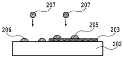
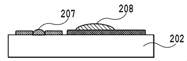
- FIGS. 1A and 1B and FIGS. 2A to 2F are diagrams for explaining this phenomenon.
- FIGS. 1A and 1B show a state when ink is first applied to a recording medium where ink has not yet been applied. Specifically, it represents a state in which cyan pigment ink is applied to a recording medium which is so-called glossy paper.
- the cyan pigment ink 101 is driven into the recording medium 102 (FIG. 1A)
- the moisture and solvent of the ink penetrate into the recording medium and evaporate, and the solid content 103 of the pigment ink is fixed on the recording medium 102 (FIG. 1B).
- FIGS. 2A to 2F show the fixing state when ink is applied to a recording medium, which is glossy paper, and the ink is fixed, and another ink is applied to that portion.
- a sufficient amount of cyan ink 201 is applied to the recording medium 202 (FIG. 2A)
- a cyan ink layer 203 is formed (FIG. 2B).
- the magenta ink 204 is ejected (FIG. 2C)
- the magenta ink ejected on the cyan ink layer 203 is compared with the magenta ink droplet 206 ejected in a place where the ink layer 203 is not present.
- the penetration completion time of the droplet 205 is delayed (FIG. 2D).
- the ink layer 210 formed by beading in this way exhibits a grainy feeling in the recorded image and causes a reduction in image quality.
- the reason for the difference in the permeation completion time is considered to be that the ink layer has a pore structure packed more densely than the recording medium.
- FIGS. 2A to 2F an example in which inks that are sequentially ejected are ejected to adjacent positions (the relationship between the ink droplet 205 and the ink 207 shown in FIG. 2D) has been described. Of course, it does not occur only in examples.
- the same permeation speed problem also occurs when ink ejected at a certain timing overlaps with the same position as the ink ejected at the previous timing.
- the same problem may occur when the dots are sequentially shot at a contactable distance depending on the size of the landed ink droplet.
- the time required for completion of penetration may vary depending on the ink characteristics of the inks that are sequentially ejected. I understand. That is, when two or more types of ink are used, the order in which the inks overlap depends on the order in which these inks are ejected, and the overall penetration completion time varies accordingly. May cause beading.
- the permeation speed with respect to the ink layer varies depending on the type of ink, but the main factor is the filling rate of the pore structure formed by the ink solid content on the recording medium.
- a pigment and a resin are included in the ink, a pore structure is formed in a form in which the resin is buried between the pigment particles on the recording medium.
- the permeation rate with respect to the ink layer varies depending on the remaining ratio of pores not filled in the pore structure (hereinafter also referred to as “P / B value”). That is, as the P / B value increases, the ink layer has a sparse filling structure, so that the penetration of ink that is subsequently applied becomes faster.
- carbon black generally used as a black pigment forms a tufted structure of grapes in which primary particles are fused together.
- the permeation speed with respect to the ink layer varies depending on the structure.
- the degree of structure size is indicated by the DBP oil absorption, and this DBP oil absorption indicates a value measured by the JIS K6221 A method. That is, when the amount of DBP oil absorption is high, a bulky ink layer is formed when the ink layer is formed, and the permeation speed of the ink to be driven next is increased.
- the DBP oil absorption amount is low, an ink layer having a high density is formed when the ink layer is formed, and the permeation speed of the subsequent ink is slowed down.
- An object of the present invention is to reduce image quality degradation due to beading or the like caused by contact of different types of ink.
- the first ejection unit for ejecting the first ink the second ejection unit for ejecting the second ink of a different type from the first ink, and recording.
- An inkjet recording apparatus that records an image on the recording medium by ejecting the first and second inks from the first and second ejection units, respectively, during relative movement with the medium.
- the permeation speed of the first ink when the first ink is ejected on the second ink ejected onto the medium is such that the second ink is ejected onto the first ink ejected onto the recording medium.
- the ratio of the pixels that are slower than the permeation rate of the second ink when ejected in layers and the second ink is ejected after the first ink is ejected is that the second ink is ejected.
- the first ink is ejected after the first ink is discharged So that more than the proportion, an ink jet recording apparatus is provided which ejection timing of the first and second ink according to the first and second discharge portion is controlled.
- the first ejection unit for ejecting the first ink and the second ejection unit for ejecting the second ink of a different type from the first ink are used.
- An inkjet recording apparatus for recording on a recording medium wherein the first and second ejection units and the recording medium are moved by means of relative movement, and the first ejection unit First image data to be recorded in a predetermined area is divided into a first divided image data group corresponding to a plurality of relative movements by the moving means, and the recording medium is predetermined by the second ejection unit.
- Dividing means for dividing the second image data to be recorded in the area into the second image data group corresponding to the plurality of relative movements, and during the plurality of relative movements with respect to the predetermined area of the recording medium.
- the first divided image data Ejection control means for ejecting the first ink from the first ejection unit according to the data group and ejecting the second ink from the second ejection unit according to the second divided image data group.
- the permeation speed of the first ink when the first ink is ejected on top of the second ink ejected onto the recording medium is determined based on the first ink ejected onto the recording medium.
- the dividing speed is slower than the permeation speed of the second ink, and the dividing means is the ratio of the pixels from which the second ink is ejected after the first ink is ejected.
- an ink jet recording apparatus that divides the first and second image data so that the ratio of the pixels from which the first ink is ejected after the second ink is ejected is larger. .
- the first ejection unit for ejecting the first ink and the second ejection unit for ejecting the second ink of a different type from the first ink are used.
- An inkjet recording apparatus for recording on a recording medium wherein the first and second ejection units and the recording medium are moved by means of relative movement, and the first ejection unit
- the first image data to be recorded in the predetermined area is a first mask corresponding to the plurality of relative movements using a first mask having a recording allowable ratio corresponding to the plurality of relative movements by the moving means.
- the second cell that has And dividing means for dividing into a second image data group corresponding to the plurality of relative movements, and the first divided image data during the plurality of relative movements with respect to a predetermined area of the recording medium.
- Discharge control means for discharging the first ink from the first discharge unit according to a group and discharging the second ink from the second discharge unit according to the second divided image data group.
- the permeation speed of the first ink when the first ink is ejected over the second ink ejected onto the recording medium is the first ink ejected onto the recording medium.
- the recording allowable ratio corresponding to the relative movement of the second half of the plurality of relative movements in the second mask is slower than the permeation speed of the second ink when two inks are ejected in a superimposed manner.
- mask Serial plurality of high jet recording apparatus from the print permitting ratio corresponding to the relative movement of the last half of one of the relative movement is provided.
- the first ejection unit for ejecting the first ink and the second ejection unit for ejecting the second ink of a different type from the first ink are used.
- An inkjet recording apparatus for recording on a recording medium wherein the first and second ejection units and the recording medium are moved by means of relative movement, and the first ejection unit
- the first image data to be recorded in the predetermined area is a first mask corresponding to the plurality of relative movements using a first mask having a recording allowable ratio corresponding to the plurality of relative movements by the moving means.
- the second cell that has And dividing means for dividing into a second image data group corresponding to the plurality of relative movements, and the first divided image data during the plurality of relative movements with respect to a predetermined area of the recording medium.
- Discharge control means for discharging the first ink from the first discharge unit according to a group and discharging the second ink from the second discharge unit according to the second divided image data group.
- the permeation speed of the first ink when the first ink is ejected over the second ink ejected onto the recording medium is the first ink ejected onto the recording medium.
- the first ejection section for ejecting the first ink and the second ejection section for ejecting the second ink of a different type from the first ink and the recording are ejecting the first and second inks from the first and second ejection units, respectively, during relative movement with the medium.
- the permeation speed of the first ink when the first ink is ejected on the second ink ejected onto the medium is such that the second ink is ejected onto the first ink ejected onto the recording medium.
- the ratio of the pixels that are slower than the permeation rate of the second ink when ejected in layers and the second ink is ejected after the first ink is ejected is that the second ink is ejected.
- the first ink is ejected after the first ink is discharged As many consisting ratio, said first and inkjet recording method of the second ejection timing of the first and second ink by the ejection portion is being controlled is provided.
- the first ejection unit for ejecting the first ink and the second ejection unit for ejecting the second ink of a different type from the first ink are used.
- An ink jet recording method for recording on a recording medium comprising: preparing a moving means for performing relative movement between the first and second ejection units and the recording medium; and First image data to be recorded in a predetermined area of the recording medium is divided into a first divided image data group corresponding to a plurality of relative movements by the moving means, and the second ejection unit A dividing step for dividing the second image data to be recorded in the predetermined area of the recording medium into the second image data group corresponding to the plurality of relative movements, and a plurality of times for the predetermined area of the recording medium;
- the second ink is ejected after the first ink is ejected.
- An ink jet recording method that divides the first and second image data so that a ratio is larger than a ratio of pixels from which the first ink is ejected after the second ink is ejected. Provided .
- the first ejection unit for ejecting the first ink and the second ejection unit for ejecting the second ink of a different type from the first ink are used.
- An ink jet recording method for recording on a recording medium comprising: preparing a moving means for performing relative movement between the first and second ejection units and the recording medium; and First image data to be recorded in a predetermined area of the recording medium is subjected to the plurality of relative movements using a first mask having a recording allowable ratio corresponding to the plurality of relative movements by the moving unit. Recording the second image data to be recorded in a predetermined area of the recording medium by the second ejection unit and corresponding to the plurality of relative movements.
- a recording allowable ratio corresponding to the relative movement of the second half of the plurality of relative movements in the second mask is slower than the permeation speed of the second ink when the second ink is ejected in an overlapping manner.
- the first It said plurality of high jet recording method the recording permitting ratio corresponding to the relative movement of the last half of one of the relative movement in the disk are provided.
- the first ejection unit for ejecting the first ink and the second ejection unit for ejecting the second ink of a different type from the first ink are used.
- An ink jet recording method for recording on a recording medium comprising: preparing a moving means for performing relative movement between the first and second ejection units and the recording medium; and First image data to be recorded in a predetermined area of the recording medium is subjected to the plurality of relative movements using a first mask having a recording allowable ratio corresponding to the plurality of relative movements by the moving unit. Recording the second image data to be recorded in a predetermined area of the recording medium by the second ejection unit and corresponding to the plurality of relative movements.
- the recording allowable ratio corresponding to the final relative movement among the plurality of relative movements in the second mask is slower than the permeation speed of the second ink when the second ink is ejected in an overlapping manner.
- the first machine Wherein the plurality of times of the last round of high jet recording method the recording permitting ratio corresponding to the relative movement of the relative movement is provided in the click.
- the permeation speed of the first ink when the first ink is ejected over the second ink ejected onto the recording medium is the first ink ejected onto the recording medium.
- the ratio of pixels from which the second ink is ejected after the first ink is ejected when the penetration speed of the second ink is slower than when the second ink is ejected over the ink.
- the first and second inks by the first and second ejection portions are larger in proportion to the ratio of pixels from which the first ink is ejected after the second ink is ejected.
- the discharge timing is controlled.
- the proportion of pixels from which the second ink is ejected after the first ink is ejected is that the first ink is ejected after the second ink is ejected.
- the first image data and the second image data are divided so as to be larger than the ratio of pixels to be processed.
- the print allowable ratio corresponding to the second half or the last half of the plurality of relative movements is set to be greater than the second mask for the first ink than the second mask for the second ink. Increase in one mask.
- FIG. 1A is a diagram for explaining fixing of ink according to a penetration speed.
- FIG. 1B is a diagram for explaining fixing of ink according to the penetration speed.
- FIG. 2A is a diagram for explaining that beading is likely to occur according to the penetration rate.
- FIG. 2B is a diagram for explaining that beading is likely to occur according to the penetration rate.
- FIG. 2C is a diagram for explaining that beading is likely to occur according to the penetration rate.
- FIG. 2D is a diagram for explaining that beading is likely to occur according to the penetration rate.
- FIG. 2E is a diagram for explaining that beading is likely to occur according to the penetration rate.
- FIG. 2F is a diagram for explaining that beading is likely to occur according to the penetration rate.
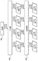
- FIG. 3 is a diagram schematically showing the relationship between the print head and the print medium in 2-pass multi-pass printing.
- FIG. 4A is a diagram for explaining the printing order with respect to the unit area when performing two-pass multi-pass printing using C, M, and Y inks as shown in FIG.
- FIG. 4B is a diagram for explaining the recording order with respect to the unit area when performing two-pass multi-pass printing using C, M, and Y inks as shown in FIG.
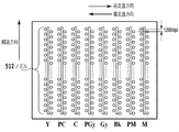
- FIG. 5 shows yellow (Y), light cyan (PC), cyan (C), light gray (PGy), gray (Gy), black (Bk), light magenta (PM), and magenta (M) inks. It is a figure which shows the recording head which arranged the nozzle.
- FIG. 4A is a diagram for explaining the printing order with respect to the unit area when performing two-pass multi-pass printing using C, M, and Y inks as shown in FIG.
- FIG. 4B is a diagram for explaining the recording order with
- FIG. 6 is a block diagram mainly showing hardware and software configurations of a personal computer as an image data generation apparatus according to an embodiment of the present invention.
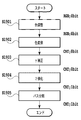
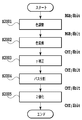
- FIG. 7 is a flowchart illustrating binary (ejection) data generation processing for each pass according to the first embodiment of the present invention.
- FIG. 8A is a diagram showing a recording ratio of a mask according to one conventional example.
- FIG. 8B is a diagram showing a mask printing ratio according to a conventional example.
- FIG. 9A is a view showing a mask used in the first embodiment.
- FIG. 9B is a diagram showing a mask used in the first embodiment as well.
- FIG. 10 is a diagram showing a mask pattern in which a recording ratio is determined for each of the C and M ink passes shown in FIGS. 9A and 9B.
- FIG. 10 is a diagram showing a mask pattern in which a recording ratio is determined for each of the C and M ink passes shown in FIGS. 9A and 9B.
- FIG. 11A is a diagram illustrating the ink ejection amount for each pass when the mask according to the above-described conventional example is used.
- FIG. 11B is a diagram showing the amount of ink applied for each pass when the mask according to the conventional example is used.
- FIG. 12A is a diagram showing a mask for 2-pass multi-pass printing according to a conventional example.
- FIG. 12B is a diagram showing a mask for 2-pass multi-pass printing according to a conventional example.
- FIG. 13 is a diagram showing a mask for two-pass multi-pass printing according to the second embodiment of the present invention.
- FIG. 14 is a diagram illustrating an example of processing for distributing binary data to four planes for two colors of ink and two passes when performing two-pass multi-pass printing according to a modification of the second embodiment. is there.
- FIG. 15 is a diagram showing a mask pattern in which a printing ratio is determined for each pass of two types of black ink used in the third embodiment of the present invention.
- FIG. 16A is a diagram showing a mask of a conventional example for comparison.
- FIG. 16B is a diagram showing a conventional mask for comparison.
- FIG. 16C is a diagram showing a conventional mask for comparison.
- FIG. 17A is a diagram showing a printing ratio for each pass of the mask of each color ink according to the fourth embodiment of the present invention.
- FIG. 17B is a diagram showing the printing ratio for each pass of the mask of each color ink according to the fourth embodiment of the present invention.
- FIG. 17C is a diagram illustrating a printing ratio for each pass of the mask of each color ink according to the fourth embodiment of the present invention.
- FIG. 18 is a diagram showing a mask pattern according to the fourth embodiment.
- FIG. 19 is a flowchart showing the processing of the first to fourth embodiments of the present invention.
- FIG. 20 is a flowchart showing the processing of the fifth embodiment of the present invention.
- FIG. 21 is a flowchart for explaining the path division and binarization processing according to the fifth embodiment.
- FIG. 22 is a block diagram illustrating details of the path division processing according to the fifth embodiment.
- FIG. 23A is a diagram illustrating the recording density of each color and each pass in the pass division processing according to the fifth embodiment.
- FIG. 23B is a diagram illustrating the recording density of each color and each pass in the pass division processing according to the fifth embodiment.
- One embodiment of the present invention relates to so-called multi-pass printing in which ink is ejected in two scans for each of cyan (C), magenta (M), and yellow (Y) inks.
- binary image data hereinafter referred to as “dot data” or “ejection data” for driving the recording heads for C, M, and Y inks corresponding to the recording operation divided into two scans.
- ejection data binary image data
- a set of image data (binary data or multi-value data) distinguished by these colors and scanning is referred to as a “plane”.
- FIG. 3 is a diagram schematically showing the relationship between the print head and the print medium in 2-pass multi-pass printing.
- an image to be recorded in a predetermined unit area of the recording medium is completed by scanning the recording head twice.
- each color nozzle group of cyan, magenta, and yellow is divided into two groups of a first group and a second group, and each group includes 256 nozzles. Accordingly, the number of nozzles of each color of the recording head is 512 each.
- Each color nozzle group discharges ink to each unit area corresponding to the arrangement width of the nozzle group on the recording medium while scanning in a direction substantially perpendicular to the nozzle arrangement direction ("head scanning direction" indicated by an arrow in the drawing).
- C, M, and Y inks are ejected to each unit area based on binary image data of C, M, and Y, respectively.
- the recording medium has a width equal to the width of one group (here, the same 256 as the width of the unit area) in the direction orthogonal to the scanning direction (the “recording medium conveyance direction” indicated by the arrow in the figure). It is transported pixel by pixel). Thereby, an image to be recorded in each unit area is completed by two scans.
- the first group of the C nozzle group, the first group of the M nozzle group, and the first group of the Y nozzle group are used in the order of CMY. Recording is performed.
- the second group of the C nozzle group, the second group of the M nozzle group, and the second group of the Y nozzle group are arranged in the order of YMC with respect to the area A where the printing in the first scan is completed. Used to record the rest.
- recording is performed in the order of YMC using the first group of the C nozzle group, the first group of the M nozzle group, and the first group of the Y nozzle group. Further, by continuing such an operation, recording is performed for each unit area in the order of C1M1Y1Y2M2C2 or in the order of Y1M1C1C2M2Y2.
- FIGS. 4A and 4B are diagrams for explaining the recording order with respect to unit areas when performing 2-pass multi-pass printing using C, M, and Y inks as shown in FIG.
- FIG. 4A shows a state where an image of an area (area A in FIG. 3) recorded in the order of forward scanning and backward scanning is completed.
- the forward scan (first pass) which is the first scan
- a cyan image is recorded based on cyan binary data.
- images of magenta and yellow are similarly recorded based on the binary data. That is, the magenta image is overlaid on the cyan image recorded before that, and the yellow image is overlaid on the preceding cyan and magenta images, and sequentially recorded.
- beading may occur as described above with reference to FIGS. 2A to 2F. Therefore, in the backward scanning (second pass) which is the second scanning, the data is sequentially generated by data division described later. Based on binary data of yellow, magenta, and cyan, respectively, images are sequentially recorded so as to be superimposed on images recorded before that.
- FIG. 4B shows a state in which an image of an area (area B in FIG. 3) recorded in the order of backward scanning and forward scanning is completed.
- the reverse scan which is the first scan
- a yellow image is recorded based on the binary binary data.
- the same scanning is performed for each of magenta and cyan based on the binary data. That is, the magenta image is overlaid on the yellow image recorded earlier than that, and the cyan image is overlaid on the yellow and magenta images recorded earlier than the yellow image.
- the forward scan which is the second scan after the recording medium is transported by a predetermined amount, similarly, based on binary data of cyan, magenta, and yellow respectively, Overlapping and recording sequentially.
- FIG. 5 shows yellow (Y), light cyan (PC), cyan (C), light gray (PGy), gray (Gy), black (Bk), light magenta (PM), and magenta (M) inks.
- Y yellow
- PC light cyan
- C cyan
- PEG light gray
- Gy gray
- Bk light magenta
- M magenta
- FIG. 6 is a block diagram mainly showing hardware and software configurations of a personal computer (hereinafter also simply referred to as a PC) as an image data generation apparatus according to an embodiment of the present invention.
- a PC personal computer
- the PC 100 that is the host computer operates each software of the application software 101, the printer driver 103, and the monitor driver 105 by the operating system (OS) 102.
- the application software 101 performs processing related to a word processor, spreadsheet, internet browser, and the like.
- the monitor driver 104 executes processing such as creating image data to be displayed on the monitor 106.
- the printer driver 103 performs image processing on image data or the like issued from the application software 101 to the OS 102 and finally generates binary ejection data used by the printer 104. Specifically, binary image data of C, M, and Y used in the printer 104 is generated from multivalued image data of C, M, and Y. The binary image data generated in this way is transferred to the printer 104.
- the host computer 100 includes a CPU 108, a hard disk drive (HD) 107, a RAM 109, a ROM 110, and the like as various hardware for operating the above software. That is, the CPU 108 executes the process according to the software program stored in the hard disk 107 or the ROM 110, and the RAM 109 is used as a work area when the process is executed.
- a CPU 108 executes the process according to the software program stored in the hard disk 107 or the ROM 110
- the RAM 109 is used as a work area when the process is executed.
- the printer 104 of the present embodiment is a so-called serial printer that performs recording by scanning a recording medium that ejects ink with respect to a recording medium and ejecting ink during that time, as described with reference to FIG.
- a recording medium such as recording paper.
- a recording element such as an electrothermal conversion element or a piezoelectric element is provided in a flow path communicating with each ejection port of the recording head, and ink is ejected from the ejection port by driving these recording elements.
- the array density of each ejection port is 1200 dpi, and 3.0 picoliters of ink is ejected from each ejection port.
- the number of discharge ports in each color discharge port group is 512.
- the printer 104 includes a CPU, a memory, and the like (not shown).
- the binary image data transferred from the host computer 100 is stored in the memory of the printer 104. Then, the binary image data stored in the memory is read out under the control of the CPU of the printer, and the processing described later in FIG. 7, FIG. 14 and FIG. 21 is performed, and then the binary data is recorded. It is sent to the head drive circuit.
- the drive circuit drives the recording element of the recording head based on the sent binary image data, and ejects ink from the ejection port.
- the CPU of the printer functions as a unit that causes each component unit to execute multi-pass printing as described in some embodiments below.
- ink having a smaller P / B value is printed in a later pass.
- C ink ink having a relatively small P / B value
- M ink ink having a relatively large P / B value
- the amount of C ink having a relatively small P / B value is increased in a pass after the relatively large M ink.
- the “amount of ink to be ejected” or the “injection amount of ink” refers to the amount of ink that is ejected (discharged) per unit area, specifically the number of ejections (the number of ejections). More specifically, it refers to the ratio of the number of inks that are applied to the pixels that constitute the unit area region. For example, the ejection when ink is applied once to all the pixels that constitute the unit area region. The amount can be expressed as 100%.
- 4-pass multi-pass printing is performed in both directions of reciprocating scanning.
- FIG. 7 is a flowchart illustrating binary (discharge) data generation processing for each pass according to the present embodiment. The process shown in FIG. 7 is executed by the printer 104 of this embodiment.
- step 701 binary data for one scan sent from the PC 100 and stored in a predetermined memory is acquired.
- information on the amount of ink applied for each unit area for which printing is completed in four passes and information on the permeation speed described below for each ink to be used are acquired.
- the unit area is an area having a size of 16 pixels ⁇ 16 pixels in this embodiment, and binary data generation (pass division) for each scan using a mask as will be described later for each unit area. ) Process.
- step 702 it is determined whether or not the permeation speeds VMC and VCM between the C and M inks differ for each unit region, and whether the ink placement amount in the unit region is equal to or greater than a predetermined amount. Specifically, the combination of the ink colors of the binary data constituting the unit area and the hit amount are determined. In the case of the present embodiment, the type of ink used in the apparatus is determined, and the ink permeation speed varies with any combination of inks used. Therefore, actually, in step 702, only the amount of driving is determined. That is, the process proceeds to the next step 703 or 706 in accordance with the determination of the ink ejection amount of binary data constituting the unit area.
- the binary data constituting the unit area is two types of C and M.
- C and M For example, when two types of Y and M inks are used to record a green color, other two types of binary data are used.
- the same processing as that described below is performed.
- the same processing is basically applied to the case of recording a gray or black tertiary color with three types of C, M, and Y, and the case of recording using three or more types of ink, as will be described later. I do.
- the same processing can be performed even when a light ink having a lighter color material density such as a dye or a pigment is used.
- the P / B value of the C ink for the recording medium is smaller than the P / B value of the M ink. That is, the C ink has a sealing action on the M ink.
- the relationship of the permeation speed when one ink is driven into the other ink layer is determined. That is, the C and M inks have a relationship of VCM ⁇ VMC with respect to the penetration speed.
- VAB represents the permeation speed of ink B when ink B is ejected into a layer formed by ink A having already been ejected
- VBA represents the opposite.
- VCM and VMC are different, it is determined that “the permeation speeds are different”. In the present embodiment, as described above, this determination is not performed, only the ink ejection amount is determined, and the process proceeds to the next step according to the determination.
- the driving amount is a predetermined amount or more.
- step 702 When it is determined in step 702 that the condition that “the permeation speeds VMC and VCM between the C and M inks are different and the ink ejection amount in the unit area is equal to or larger than the predetermined amount” is not satisfied (cases 1 and 3 described later are included)
- step 705 path division is performed. That is, the acquired binary data is subjected to mask processing using a mask that defines a unit area for completing printing in four passes and a printing ratio for each pass, and generates ejection data for each pass. As this mask, the mask described for cases 1 and 3 is used.
- step 702 when it is determined in step 702 that the condition that “the permeation speeds VMC and VCM between the C and M inks are different and the ink ejection amount in the unit area is equal to or greater than the predetermined amount” is satisfied (case 2 described later is included).
- step 703 VAB and VBA are compared.
- VAB is smaller than (slower) than VBA
- step 704 A ink is driven in a later pass.
- step 705 when VBA is smaller than VAB (slow), in step 705, B ink is driven in a later pass.
- step 704 or step is performed according to the combination of the ink types of the data constituting the unit area obtained in step 702.
- a mask used for path division is set. More specifically, for each combination of two types of ink used in the apparatus, a mask for each type of ink is determined in advance.
- step 704 or step 705 a mask corresponding to the combination obtained in step 702 is read out. Process.
- a mask is not defined for each of two types of combinations obtained from these four types of inks, but relative penetration of each of the four types of inks. Based on the speed relationship, a mask for each of the four types of ink may be determined. The mask determined in this way may satisfy the relationship described below as a mask for each of the two types of ink obtained in step 702.
- the amount (ratio) of C ink that makes the permeation speed slower is driven in the later passes among the four passes that complete the recording.
- a process of setting a mask used in the pass division in step 706 is performed according to the magnitude relationship of the penetration speed.
- the center of gravity of the recording ratio with respect to the pass of the C ink mask that slows the permeation speed is set to be a pass relatively later than the center of gravity of the M ink mask.
- the pass is determined according to the combination of the color (ink type) of the binary data constituting the image of the unit area determined in step 702 and the ink ejection amount obtained from the binary data. Carving out the mask used for division. Even in the case where there are three or more types of binary data ink constituting the image of the unit area, the mask to be used can be divided in the same manner.
- the binary data constituting the image of the unit area includes C, M, and Y types in the same manner as described above. It detects that it is a combination of inks.
- the ink used in the apparatus of this embodiment since it is known that the ink used in the apparatus of this embodiment has different permeation speeds, immediately determine the ink ejection amount of each ink of the combination and the total ink ejection amount that is the sum thereof, It is determined whether or not each is a predetermined amount or more.
- the criteria for this determination are, for example, that the amount of ink injected in the order of slowing the permeation rate is 60% or more, 40% or more, 30% or more, and the total of C, M, and Y inks. When the hit amount exceeds 120%, it can be determined that “the ink hit amount is a predetermined amount or more”.
- step 702 the mask use separation processing is performed in the same manner as described above, and the first mask is set using the mask set thereby.
- the path division is performed as described later in the fourth embodiment.
- Cases 1, 2 and 3 are distinguished according to the combination of the hit amounts for the unit areas of C and M inks, respectively.
- Case 1 When C ink is applied alone (100%: 0%)
- Case 2 When a large amount of C ink and M ink is applied (100%: 100%)
- Case 3 C ink and M ink When a small amount is hit (25%: 25%)
- Case 1 is a case where only C ink is printed, and corresponds to a case where a cyan image is recorded.
- This case 1 is an example in which it is determined in step 702 of FIG. 7 that the condition that “the permeation speeds VMC and VCM between the C and M inks are different and the ink ejection amount in the unit area is not less than a predetermined amount” is not satisfied. is there.
- the permeation speeds VMC and VCM between the C and M inks used in this embodiment are different. That is, this case is a case where the permeation speeds VMC and VCM between the C and M inks are different, but the condition that “the ink ejection amount in the unit area is equal to or larger than the predetermined amount” is not satisfied.
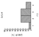
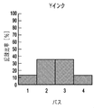
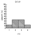
- FIG. 8A and 8B are diagrams showing the masks used in case 1. Specifically, FIG. 8A shows the recording ratio for each pass of C ink, and FIG. 8B shows the recording ratio for each pass of M ink.
- the mask is constituted by a mask element that defines “output (recording allowance)” / “non-output (recording nonallowance)” of the recording data of the pixel corresponding to the pixel of the recording data, and the “recording ratio” (Also referred to as “recording allowance ratio”) represents the ratio of mask elements that define “output (recording allowance)” of the record data.
- the patterns of the mask elements of the respective masks corresponding to the multiple passes used for completing the recording of the unit area by multiple passes (scanning) as in this example are complementary to each other.
- the sum of the mask recording allowable ratios corresponding to these multiple passes is 100%.
- the contents of the C and M ink masks used in Case 1 are the same. That is, these masks are so-called gradation masks in which the printing allowance ratio of the first pass and the fourth pass is lower than the printing allowance ratio of the second pass and the third pass.
- the recording allowable ratio is 12.5%, 37.5%, 37.5%, and 12.5% in order from the first pass.
- the amount of M ink applied to the unit area is 0% as described above, so an M ink image is not actually recorded.
- Case 2 corresponds to recording a dark blue image.
- Case 2 is an example in which inks of two colors C and M are equally used, and both inks are recorded in a relatively large amount.
- This case 2 is a case where it is determined in step 702 of FIG. 7 that the condition that “the permeation speeds VMC and VCM between the C and M inks are different and the ink ejection amount in the unit area is a predetermined amount or more” is satisfied. .
- the occurrence of beading due to the capping of the C ink that has been previously printed becomes significant. Therefore, in order to improve the decrease in the entire permeation rate due to the sealing of the C ink, a mask is used in which the C ink is driven in as many passes as possible.
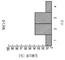
- FIGS. 9A and 9B are diagrams showing masks used in case 2, in which FIG. 9A shows a print allowable ratio for each pass of C ink, and FIG. 9B shows a print allowable ratio for each pass of M ink.
- the allowable recording ratios of the first to fourth pass masks of C ink are 6.2%, 37.5%, 37.5%, and 18.8%, respectively.
- the print allowable ratios of the first to fourth pass masks of M ink are 12.5%, 37.5%, 37.5%, 12. 5%.
- the C ink has a higher print allowable ratio in the last fourth pass than that of the M ink, and accordingly, the print allowable ratio in the first pass becomes a mask lower than that of the M ink.
- the C ink uses a mask that has a higher printing allowance ratio in the latter half pass than the M ink (in the case of 4 passes, the total print allowance ratio of the third pass and the fourth pass), and the M ink is more than the C ink
- the amount of M ink to be subsequently applied to C ink having a high sealing effect can be reduced, and the overall decrease in the permeation speed is suppressed. be able to.
- having the above relationship in the second half pass is a reverse relationship to the above in the first half pass because each mask has a complementary relationship between the passes.
- the above relationship in the second half pass guarantees that each mask is determined so that more C ink is applied in a later pass as compared with M ink in the entire mask corresponding to each pass.
- the C ink uses a mask having a higher printing allowance ratio in the final pass than the M ink
- the M ink uses a mask having a lower print allowance ratio in the final pass than the C ink. You may do it.
- the C ink that acts to “reducing the penetration rate of ink to be ejected later by sealing” is subsequently applied. It is possible to reduce the amount of M ink that is driven in, and to suppress a decrease in the permeation speed as a whole. As a result, occurrence of beading due to a long penetration completion time can be suppressed.
- the above-mentioned “second half pass” is, for example, the (n + 2) th pass and (n + 3) pass excluding the center pass. Eyes, 2nd pass, (2n + 1) th pass.
- the center of gravity can be expressed by the following equation. ⁇ (n ⁇ fX (n)) / ⁇ fX (n)
- fX (n) means the allowable printing ratio for the nth pass of X ink
- ⁇ means the sum from 1 to the total number N of passes for n.
- 9A means that the center of gravity is between the second pass and the third pass and is closer to the third pass. And, when the center of gravity is “near the third pass between the second pass and the third pass” than when the center of gravity is “just in the middle of the second pass and the third pass”, that is, A larger value means that the amount of ink that is ejected in a later pass increases.
- the position of the center of gravity is 2.5, that is, exactly the middle between the second pass and the third pass.
- FIG. 10 is a diagram showing a mask pattern in which a print allowable ratio is determined for each pass of C and M inks shown in FIGS. 9A and 9B.
- a mask element indicated by black or diagonal lines corresponds to a pixel of print data.
- a mask element that defines “output (recording allowance)” of recording data of the pixel is shown.
- a blank mask element indicates a mask element that defines “non-output (non-permitted recording)” of recording data.
- the number of mask elements of each mask shown in FIG. 10 is 16, but this is for simplification of illustration, and the number in the nozzle arrangement direction actually corresponds to the number of nozzles of each color ink of the recording head. is doing.
- FIG. 10 also shows an ink dot pattern formed for each pass when the C and M inks are image data with 100% strike amount.
- the M and C ink masks have a print allowance ratio of 12.5% and 18.8%, respectively, so 2 and 3 mask elements out of 16 mask elements, respectively.
- the C ink that acts so as to “lower the permeation speed of ink to be ejected later by sealing” uses a mask that is ejected in a later pass as compared to the M ink.
- the proportion of pixels from which C ink is ejected after M ink is ejected is greater than the proportion of pixels from which M ink is ejected after C ink is ejected. be able to.
- Case 3 corresponds to recording a light blue image.
- the condition that “the permeation speeds VMC and VCM between the C and M inks are different and the ink ejection amount in the unit area is equal to or greater than the predetermined amount” is not satisfied.
- the permeation speeds VMC and VCM between the C and M inks used in this embodiment are different. That is, this case 3 is also a case where the permeation speeds VMC and VCM between the C and M inks are different, but the condition that “the ink ejection amount in the unit region is equal to or larger than the predetermined amount” is not satisfied.
- Case 3 is a case where the two colors C and M are used equally, but both inks are recorded in a small amount. Since the total ink ejection amount is small in this way, the same mask as in Case 1 is used for both C and M inks in order to achieve the effects of conventional multi-pass printing and gradation masks as well as Case 1. As a result, the driving amount for each pass with respect to the unit region is as shown in FIGS. 11A and 11B.
- the ink ejection amount condition for a predetermined area is used when the predetermined condition is not satisfied only when the predetermined condition is satisfied.
- the mask is changed to the characteristic mask of this embodiment described above.
- the amount of ink for each color and each pass is determined using a mask, but it is needless to say that the present invention is not limited to the form using a mask.
- the binary data is distributed to the 8 planes for 4 passes of each color ink according to the above-described print allowance ratio of each color and each pass.
- the driving amount of each plane may be determined.
- FIG. 12A and 12B are diagrams showing a mask for two-pass multi-pass recording according to a conventional example. That is, FIG. 12A shows the masks for the first pass and the second pass of the C ink, and FIG. 12B shows the masks for the first pass and the second pass of the M ink. As is apparent from these drawings, the masks for the C and M inks have the same mask (element) patterns with the same print allowable ratio in the first pass and the second pass.
- the C ink is M
- the number of pixels that overlap the ink and the number of pixels that overlap the M ink with the C ink are the same, which is 50% of the image with the 100% shot amount.
- FIG. 13 is a view showing a mask for two-pass multi-pass printing according to the second embodiment of the present invention.
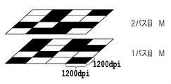
- FIG. 13 shows a case in which an image in which C and M inks are printed at 100% in the order of M ⁇ C in the first pass and C ⁇ M in the second pass is the same as the conventional example. A pattern of ink dots formed for each pass is also shown.
- the recording allowable ratio of the first pass mask of M ink is 56.25%, and the recording allowable ratio of the second pass mask is 43.75%.
- the allowable recording ratio of the mask is 50% for both the first pass and the second pass of C ink.
- the condition described above in the first embodiment is satisfied that “the center of gravity of the print allowable ratio of the C ink mask is in a pass after the center of gravity of the print allowable ratio of the M ink mask”.
- the number of pixels in which the C ink and the M ink are overlapped is 100. %. Then, 56.25% of the pixels where the C ink (first pass, second pass) is applied over the M ink are superimposed on the C ink (first pass, second pass). 43.75% will be driven in. As a result, it is possible to reduce the probability that C ink having a greater effect of “reducing the penetration speed of ink that is ejected later by the sealing” is greater, and to suppress beading.
- FIG. 14 is a diagram illustrating an example of this process. As shown in the figure, when it is determined in step 1402 that the image data of the unit area uses inks having different penetration speeds, pixels in which the penetration speed inks overlap are extracted in step 1404.
- the ink that slows the permeation speed of ink to be ejected later is distributed so as to be ejected in the later pass as much as possible.
- the C ink is distributed so as to be driven in a pass after the M ink.
- the third embodiment of the present invention relates to a mode in which a unit area is recorded by multi-pass printing of 8 passes using two types of black (K) inks using two types of carbon black as color materials as pigment color materials.
- K black
- these two types of K inks have different DBP oil absorption amounts, and an ink having a lower DBP oil absorption amount (hereinafter referred to as K ink A) has a higher DBP oil absorption amount (hereinafter referred to as K ink B). )
- K ink A an ink having a lower DBP oil absorption amount
- K ink B DBP oil absorption amount
- the components of the two types of K ink are as follows.
- the black image data has a maximum driving amount of 200% in total, that is, 100% K ink A with high DBP oil absorption and 100% K ink B with low DBP oil absorption.
- the shot amount 100% is an amount in which four 4.5 pl four ink droplets are shot into a pixel corresponding to 600 dpi ⁇ 600 dpi. That is, as described above, this is the amount that one ink droplet is driven into a pixel corresponding to 1200 dpi ⁇ 1200 dpi. That is, at the maximum hit amount, K ink A and K ink B are shot at all the pixels.
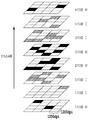
- FIG. 15 is a diagram showing masks (element patterns) in which recording ratios are determined for each pass of K ink A and K ink B used in the present embodiment.
- the mask of K ink A having a high DBP oil absorption amount injects ink into all the pixels in the unit area in the first four passes (first pass to fourth pass) (mask element 401).
- the mask of K ink B having a low DBP oil absorption amount injects ink into all the pixels in the unit area in the 4th pass (5th pass to 8th pass) after the 5th pass (mask element 402).
- the K ink A having a high DBP oil absorption amount is driven in advance of the K ink B having a low DBP oil absorption amount for all the pixels. That is, the ratio of the number of pixels in which the high DBP oil absorption K ink A is driven into the recording medium prior to the low DBP oil absorption K ink B with respect to the total number of pixels in which the high DBP oil absorption K ink A is applied. Is 100%. On the other hand, the ratio at which the low DBP oil absorption K ink B is driven before the high DBP oil absorption K ink A is 0%.
- the center of gravity of the printing allowable ratio of the ink having the lower P / B value is relatively set. Record as later.
- the following components and three types of Y, C, and M inks having P / B values are used.
- this example is a case where multi-pass printing of 4 passes is performed in both directions of the print head scanning.
- the P / B values of the Y, C, and M inks are Y ink ⁇ C ink ⁇ M ink, and the permeation speed with respect to the recording medium has the same relationship. That is, VYC ⁇ VCY, VYM ⁇ VMY, and VCM ⁇ VMC. Therefore, in the present embodiment, the recording ratio determined for each pass is made different for each of the Y, C, and M inks in accordance with the above relationship.
- the mask is set as follows.
- 16A to 16C are diagrams showing a mask of a conventional example for comparison.
- the recording allowable ratio for each color ink pass is the same, and the recording ratio is symmetrical with respect to the pass.
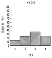
- FIGS. 17A to 17C are diagrams showing the print allowable ratio for each pass of the mask of each color ink according to the present embodiment.
- the Y ink mask recording allowable ratio is 12.5%, 25.0%, 37.5%, 25.0% for the first to fourth passes, respectively, and the same for C ink, 12.5%, 37.5. % 37.5%, 12.5%, and M ink is 25.0%, 37.5%, 25.0%, 12.5%.
- the relationship of the center of gravity of the print allowable ratio regarding the Y ink, C ink, and M ink passes is ⁇ (n ⁇ fY2 (n)) / ⁇ fY2 (n)> ⁇ (n ⁇ fC2 (n)) / ⁇ fC2 (n) ⁇ (n ⁇ fY2 (n)) / ⁇ fY2 (n)> ⁇ (n ⁇ fM2 (n)) / ⁇ fM2 (n) ⁇ (n ⁇ fC2 (n)) / ⁇ fC2 (n)> ⁇ (n ⁇ fM2 (n)) / ⁇ fM2 (n) It becomes.
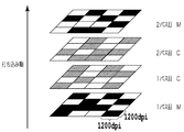
- FIG. 18 is a diagram showing the mask of this embodiment as a mask element pattern.
- the pattern of ink dots formed for each pass when Y, C, and M inks are image data with 100% ejection amount, respectively. It is also an indication.
- the P / B value of each of the Y, C, and M inks the smaller the P / B value, the larger the amount to be ejected in the later pass. This makes it possible to increase the amount of ink to be applied in a later pass and to suppress beading as the degree of the ink having the effect of “decreasing the permeation rate of ink to be applied later by sealing” increases. Become.
- the first to fourth embodiments described above are processed according to the flowchart shown in FIG. That is, after binarization processing (S1904), processing for distributing to each path (S1905; path division) is performed.
- the present invention can be applied to other processes. As an example, it can be applied to a process of performing binarization (S2005) after path division (S2004) according to the flowchart shown in FIG.
- FIG. 21 is a flowchart illustrating binary (discharge) data generation processing for each pass according to the present embodiment.
- the processing shown in FIG. 21 is executed by the printer 104 of this embodiment.
- the recording method is the same (multi-pass recording with four passes in both directions of reciprocating scanning).
- FIG. 22 is a diagram for explaining a specific example.
- Each of the ink amounts of C ink and M ink in the multi-value data is 100%.
- the pass division is performed with the multivalued data so that the center of gravity of the recording ratio with respect to the C ink pass is relatively behind the center of gravity of the M ink.
- FIG. 23A and FIG. 23B show the recording density (ink ejection amount) in each pass of C ink and M ink.
- the recording density of C ink in 1 to 4 passes is 6.2%, 37.5%, 37.5%, and 18.8%, respectively, and the recording density of M ink in 1 to 4 passes is 12.5%, respectively. 37.5%, 37.5%, and 12.5%.
- the path division unit 2202 adds 6.2%, 37. Multiply the ratios of 5%, 37.5%, and 18.8% to obtain 8-bit data for each pass.
- 8-bit data of each path is obtained by multiplying the 8-bit data of M by a ratio of 12.5%, 37.5%, 37.5%, and 12.5%.
- the binarization processing unit 2203 binarizes the data of each color and each pass obtained in this way to generate binary (ejection) data. Any known method can be used as the binarization method.
- the technique described in Japanese Patent No. 4273175 by the present applicant can be used as such a binarization technique.
- the recording density of each pass can be set so that more C ink is applied in a later pass than M ink. This makes it possible to reduce the amount of M ink to be applied later, and to suppress the overall decrease in the penetration speed, with respect to the C ink that acts to “lower the penetration speed of ink that is applied later by sealing”. It becomes possible. As a result, occurrence of beading due to a long penetration completion time can be suppressed.
Landscapes
- Engineering & Computer Science (AREA)
- Quality & Reliability (AREA)
- Ink Jet (AREA)
Abstract
インクジェット記録装置において、相互に重ねて打ち込まれるインクの相対的な浸透速度に応じた打ち込み順序とすることにより、ビーディングなどによる画質劣化を低減する。Cインクの1パス目~4パス目のマスクの記録比率は、それぞれ6.2%、37.5%、37.5%、18.8%である。一方、Mインクの1パス目~4パス目のマスクの記録比率は、それぞれ12.5%、37.5%、37.5%、12.5%である。このように、CインクはMインクと比べてより後のパスで多く打ち込まれるようにそれぞれのマスクが設定される。これにより、「目止めによって後から打ち込まれるインクの浸透速度を下げる」作用をするCインクに対して、後から打ち込まれるMインクの量を少なくでき、全体的に浸透速度が遅くなることを抑制することが可能となる。その結果、浸透完了時間が長くなることによるビーディングの発生を抑制することができる。
Description
本発明は、インクジェット記録装置およびインクジェット記録方法に関し、詳しくは、インク打ち込み制御によって記録画像における粒状感を低減する構成に関するものである。
近年のパーソナルコンピュータ等情報処理機器の普及に伴い、画像形成端末としての記録装置も急速に発展し、また、普及して来ている。種々の記録装置の中でも、紙などの記録媒体にインクを吐出して記録を行うインクジェット記録装置は様々な利点を有しており、パーソナルユースの主流となりつつある。インクジェット記録装置は、このような広範な普及に伴って画質のより一層の向上が求められるようになってきており、例えば、家庭で手軽に写真をプリントできるようなプリントシステムとして銀塩写真に見合う画像の品位が求められて来ている。インクジェット記録装置にあっては、銀塩写真と比べた場合、記録画像における粒状感が従来からの問題の一つである。
この粒状感を低減するための様々な対策が提案されている。例えば、通常のシアン、マゼンタ、イエローおよびブラックの外に、より色材濃度の低いライトシアンやライトマゼンタを加えたインクシステムを備えたインクジェット記録装置が知られている。すなわち、このようなインクシステムを用いることにより、記録濃度の低い領域でライトシアンやライトマゼンタを用いることによって、粒状感を低減することができる。そして、記録濃度の高い領域では通常のシアンやマゼンタを用いて記録を行うことにより、より広い色再現および滑らかな階調性を実現することも可能となる。
また、記録媒体においてインクによって形成されるドットの大きさをより小さく設計して粒状感を低減する方法もある。これは、記録ヘッドの吐出口から吐出されるインク滴を少量化するものである。この場合、インク滴の少量化のみならず、より多くの吐出口をより高い配列密度とすることによって記録速度を損なわずに高解像な画像を同時に得ることも可能となる。
粒状感を悪化させる要因としては、上述した色材濃度が高いインクや形成されるドットの大きさ以外に、インクのにじみやビーディングがある。記録媒体のインクの吸収量には限界があるので、例えば、記録媒体の一定の面積に限界を超えるインクを吐出するとインクのにじみが発生し、それが粒状感を呈する場合がある。特に、1つの画素に2色以上のインクを重ね合わせて吐出するような場合、インク吸収量の限界を超えることによるインクのにじみが発生しやすい。例えば、シアン、マゼンタ、イエローおよびブラックの4色のインクを使用する装置において、例えばレッド、ブルー、グリーンの2次色を表現する場合は、イエロー、マゼンタ、シアンの1次色を表現する場合に比べて1画素当たりに吐出するインク量が多くなる。また、このような場合に、複数のインク滴が紙面上に吸収されないで液体として存在し、それらが互いに引き合ってより大きな液滴となり、最終的に本来のドットより大きなドットを形成する現象であるビーディングが生じることもある。
これらにじみやビーディングに起因した粒状感の悪化を抑制するべく、以下のような方法が提案されている。すなわち、いわゆるマルチパス記録を行うことにより、1回の走査もしくは単位時間で、記録媒体の単位面積に打ち込まれるインクの量を少なくすることができる。これにより、記録媒体におけるインクのにじみや、記録媒体上で吸収できずに液体の状態でインク滴同士が接触することに起因したビーディングを低減できる。
また、単位時間で単位面積に打ち込まれるインク量を低減する他の方法として、特許文献1には、イエロー、マゼンタ、シアン、ブラックのインクの他、レッド、ブルーおよびグリーンの2次色に係るインクを用いることが記載されている。すなわち、レッド、ブルー、グリーンの2次色を記録するときは、上記のそれぞれレッド、ブルー、グリーンのインクを用いることにより、1つの画素に打ち込まれるインク量を少なくすることができる。
さらに、特許文献2には、2次色を記録する際に各色インクの最大吐出量を100%以下とする制限を設け、1次色インクの2色と2次色インクで記録を行うことが記載されている。
しかしながら、マルチパス記録方式において、単位時間に記録媒体の単位面積に打ち込むインク量を少なくするべくパス数を多くすると、記録に要する時間の増大を招く原因となり、スループットの向上や記録の高速化の妨げとなる。これに対し、パス数を多くする代わりに特許文献1や特許文献2に記載の方法を用い、単位面積あたりに打ち込まれるインク量を少なくすることは可能である。しかし、特許文献1、2に記載の方法を用いても、マルチパス記録のパス数が少ない場合は、2次色インクを用いることによる単位面積あたりのインクの打ち込み量の低減効果以上に、パス数が少ないことによる1回のパスあたりの打ち込み量の多さによる弊害が大きい場合がある。そして、この様な状況の場合、記録媒体の種類によっては、たとえ最終的に付与される総てのインクを吸収可能であったとしても、その途中におけるインク打ち込みに対応して吸収が不十分となることがある。
一方、本願発明者等の検討によれば、記録媒体に最初に打ち込んだインクよりも、既にインクが打ち込まれた領域に打ち込んだインクの方が、浸透が完了する時間が長く、よりビーディングを生じやすくなることが確認されている。
図1Aおよび1Bおよび図2A~2Fは、この現象を説明するための図である。
図1Aおよび1Bは、記録媒体の未だインクが打ち込まれていないところに最初にインクを打ち込んだときの状態を示している。具体的には、いわゆる光沢紙である記録媒体に対し、シアンの顔料インクを打ち込んだ状態を表している。記録媒体102に、シアン顔料インク101を打ち込むと(図1A)、インクの水分、溶剤が記録媒体内に浸透するとともに、蒸発し、顔料インクの固形分103が記録媒体102に定着する(図1B)。
一方、図2A~2Fは、光沢紙である記録媒体にインクが打ち込まれそれが定着し、その箇所にさらに別のインクが打ち込まれたときの定着の状態を示している。記録媒体202に、その表面を覆うのに十分な量のシアンのインク201が打ち込まれると(図2A)、シアンのインク層203が形成される(図2B)。そして、次に、マゼンタのインク204が打ち込まれると(図2C)、インク層203のない場所に打ち込まれたマゼンタのインク滴206と比較して、シアンインク層203上に打ち込まれたマゼンタのインク滴205の浸透完了時間が遅くなる(図2D)。その結果、さらにインク滴205、206それぞれに隣接した場所に、イエローのインク207が打ち込まれると(図2D)、インク滴205が十分に浸透していないため、インク滴205とインク滴207とによってビーディング208が引き起こされる(図2E)。そして、ビーディングによるインク層210が形成される(図2F)。一方、インク滴206はその液体成分が十分に浸透しているため、インク滴206と後から打ち込まれたインク207は連結せず(図2E)、最終的に分離した状態のインク層211が形成される(図2F)。このようにして形成されたビーディングによるインク層210は記録画像において粒状感を呈し画像品位の低下をもたらす。このような浸透完了時間に差異が生じる原因としては、インク層の方が記録媒体よりも密に充填した細孔構造になっているためと考えられる。なお、図2A~2Fを用いた説明では、順次打ち込まれるインクが隣接する位置に打ち込まれる例(図2Dに示すインク滴205とインク207との関係)について説明したが、浸透速度の問題はこの例に限って生じるものではないことはもちろんである。あるタイミングで吐出されるインクがその前のタイミングで吐出されたインクと同じ位置に打ち込まれて重なる場合も、同様の浸透速度の問題が生じる。また、逆に、打ち込まれる画素が隣接していない場合でも、着弾したインク滴の大きさによって接触可能な距離に順次打ち込まれる場合にも同様の問題を生じ得る。
さらに、本発明者等のさらなる検討によれば、既にインクが打ち込まれている箇所にインクを打ち込んだ場合、浸透が完了するまでの時間は順次に打ち込まれるインク相互の、インク特性によって異なることも判っている。すなわち、2種類以上のインクを用いた場合、これらのインクを打ち込む順序によってインクの重なる順序が異なることになり、それに応じて全体の浸透完了時間に違いを生じ、浸透完了時間が遅い場合にはビーディングを生じることがある。
インク層に対する浸透速度がインクの種類によって異なる理由は様々考えられるが、主要因としては、記録媒体上でのインク固形分が形成する細孔構造の充填率が挙げられる。例えば、インク中に顔料と樹脂が含まれる場合、記録媒体上では顔料粒子間に樹脂が埋められる形態で細孔構造が形成される。そして、これら細孔構造における、充填されていない細孔の残存比率(以下、「P/B値」とも言う)に応じてインク層に対する浸透速度が異なる。すなわち、P/B値が大きいほどインク層が疎な充填構造になるため、後続して打ち込まれるインクの浸透がより速くなる。
また、黒色顔料として一般的に使用されるカーボンブラックは、一次粒子同士が融着しぶどうの房状のストラクチャーを形成することが知られている。インクの色材にカーボンブラックが含まれる場合は、このストラクチャーの違いによってもインク層に対する浸透速度が異なる。ここで、ストラクチャーの大きさの程度はDBP吸油量で示され、このDBP吸油量は、JIS K6221 A法で測定した値を指す。つまり、このDBP吸油量が高いものはインク層を形成した際に嵩高いインク層を形成し、次に打ち込まれるインクの浸透速度が速くなる。一方、DBP吸油量が低いものはインク層を形成した際に密度の高いインク層を形成し、後続の打ち込みインクの浸透速度が遅くなる。
本発明の目的は、異なる種類のインクが接触することで生じるビーディングなどによる画質劣化を低減することにある。
本発明の第1の態様では、第1のインクを吐出するための第1の吐出部と前記第1のインクとは種類の異なる第2のインクを吐出するための第2の吐出部と記録媒体との相対移動中に、前記第1および第2の吐出部それぞれから前記第1および第2のインクを吐出して、前記記録媒体に画像の記録を行うインクジェット記録装置であって、前記記録媒体に吐出された第2インクの上に前記第1インクが重ねて吐出された場合の当該第1インクの浸透速度は、前記記録媒体に吐出された第1インクの上に前記第2インクが重ねて吐出された場合の当該第2インクの浸透速度より遅く、前記第1のインクが吐出された後に前記第2のインクが吐出される画素の割合の方が、前記第2のインクが吐出された後に前記第1のインクが吐出される画素の割合より多くなるように、前記第1および第2の吐出部による前記第1および第2のインクの吐出タイミングが制御されるインクジェット記録装置が提供される。
本発明の第2の態様では、第1のインクを吐出するための第1の吐出部と前記第1のインクとは種類の異なる第2のインクを吐出するための第2の吐出部を用いて記録媒体に記録を行うインクジェット記録装置であって、前記第1および第2の吐出部と前記記録媒体との相対移動を行うための移動手段と、前記第1の吐出部によって前記記録媒体の所定領域に記録されるべき第1の画像データを前記移動手段による複数回の相対移動に対応した第1の分割画像データ群に分割し、且つ、前記第2の吐出部によって前記記録媒体の所定領域に記録されるべき第2の画像データを前記複数回の相対移動に対応した第2の画像データ群に分割するための分割手段と、前記記録媒体の所定領域に対する複数回の相対移動中に、前記第1の分割画像データ群に従って前記第1の吐出部より前記第1のインクを吐出させると共に前記第2の分割画像データ群に従って前記第2の吐出部より前記第2のインクを吐出させる吐出制御手段と、を有し、前記記録媒体に吐出された第2インクの上に前記第1インクが重ねて吐出された場合の当該第1インクの浸透速度は、前記記録媒体に吐出された第1インクの上に前記第2インクが重ねて吐出された場合の当該第2インクの浸透速度より遅く、前記分割手段は、前記第1のインクが吐出された後に前記第2のインクが吐出される画素の割合の方が、前記第2のインクが吐出された後に前記第1のインクが吐出される画素の割合より多くなるように、前記第1および第2の画像データの分割を行うインクジェット記録装置が提供される。
本発明の第3の態様では、第1のインクを吐出するための第1の吐出部と前記第1のインクとは種類の異なる第2のインクを吐出するための第2の吐出部を用いて記録媒体に記録を行うインクジェット記録装置であって、前記第1および第2の吐出部と前記記録媒体との相対移動を行うための移動手段と、前記第1の吐出部によって前記記録媒体の所定領域に記録されるべき第1の画像データを、前記移動手段による複数回の相対移動に対応した記録許容比率をそれぞれ有する第1マスクを用いて、当該複数回の相対移動に対応した第1の分割画像データ群に分割し、且つ、前記第2の吐出部によって前記記録媒体の所定領域に記録されるべき第2の画像データを、前記複数回の相対移動に対応した記録許容比率をそれぞれ有する第2マスクを用いて、当該複数回の相対移動に対応した第2の画像データ群に分割するための分割手段と、前記記録媒体の所定領域に対する複数回の相対移動中に、前記第1の分割画像データ群に従って前記第1の吐出部より前記第1のインクを吐出させると共に前記第2の分割画像データ群に従って前記第2の吐出部より前記第2のインクを吐出させる吐出制御手段と、を有し、前記記録媒体に吐出された第2インクの上に前記第1インクが重ねて吐出された場合の当該第1インクの浸透速度は、前記記録媒体に吐出された第1インクの上に前記第2インクが重ねて吐出された場合の当該第2インクの浸透速度より遅く、前記第2マスクにおける前記複数回の相対移動のうち後半の回の相対移動に対応した記録許容比率が、前記第1マスクにおける前記複数回の相対移動のうち後半の回の相対移動に対応した記録許容比率より高いインクジェット記録装置が提供される。
本発明の第4の態様では、第1のインクを吐出するための第1の吐出部と前記第1のインクとは種類の異なる第2のインクを吐出するための第2の吐出部を用いて記録媒体に記録を行うインクジェット記録装置であって、前記第1および第2の吐出部と前記記録媒体との相対移動を行うための移動手段と、前記第1の吐出部によって前記記録媒体の所定領域に記録されるべき第1の画像データを、前記移動手段による複数回の相対移動に対応した記録許容比率をそれぞれ有する第1マスクを用いて、当該複数回の相対移動に対応した第1の分割画像データ群に分割し、且つ、前記第2の吐出部によって前記記録媒体の所定領域に記録されるべき第2の画像データを、前記複数回の相対移動に対応した記録許容比率をそれぞれ有する第2マスクを用いて、当該複数回の相対移動に対応した第2の画像データ群に分割するための分割手段と、前記記録媒体の所定領域に対する複数回の相対移動中に、前記第1の分割画像データ群に従って前記第1の吐出部より前記第1のインクを吐出させると共に前記第2の分割画像データ群に従って前記第2の吐出部より前記第2のインクを吐出させる吐出制御手段と、を有し、前記記録媒体に吐出された第2インクの上に前記第1インクが重ねて吐出された場合の当該第1インクの浸透速度は、前記記録媒体に吐出された第1インクの上に前記第2インクが重ねて吐出された場合の当該第2インクの浸透速度より遅く、前記第2マスクにおける前記複数回の相対移動のうち最終回の相対移動に対応した記録許容比率が、前記第1マスクにおける前記複数回の相対移動のうち最終回の相対移動に対応した記録許容比率より高いインクジェット記録装置が提供される。
本発明の第5の態様では、第1のインクを吐出するための第1の吐出部と前記第1のインクとは種類の異なる第2のインクを吐出するための第2の吐出部と記録媒体との相対移動中に、前記第1および第2の吐出部それぞれから前記第1および第2のインクを吐出して、前記記録媒体に画像の記録を行うインクジェット記録方法であって、前記記録媒体に吐出された第2インクの上に前記第1インクが重ねて吐出された場合の当該第1インクの浸透速度は、前記記録媒体に吐出された第1インクの上に前記第2インクが重ねて吐出された場合の当該第2インクの浸透速度より遅く、前記第1のインクが吐出された後に前記第2のインクが吐出される画素の割合の方が、前記第2のインクが吐出された後に前記第1のインクが吐出される画素の割合より多くなるように、前記第1および第2の吐出部による前記第1および第2のインクの吐出タイミングが制御されることを特徴とするインクジェット記録方法が提供される。
本発明の第6の態様では、第1のインクを吐出するための第1の吐出部と前記第1のインクとは種類の異なる第2のインクを吐出するための第2の吐出部を用いて記録媒体に記録を行うインクジェット記録方法であって、前記第1および第2の吐出部と前記記録媒体との相対移動を行うための移動手段を用意する工程と、前記第1の吐出部によって前記記録媒体の所定領域に記録されるべき第1の画像データを前記移動手段による複数回の相対移動に対応した第1の分割画像データ群に分割し、且つ、前記第2の吐出部によって前記記録媒体の所定領域に記録されるべき第2の画像データを前記複数回の相対移動に対応した第2の画像データ群に分割するための分割工程と、前記記録媒体の所定領域に対する複数回の相対移動中に、前記第1の分割画像データ群に従って前記第1の吐出部より前記第1のインクを吐出させると共に前記第2の分割画像データ群に従って前記第2の吐出部より前記第2のインクを吐出させる吐出制御工程と、を有し、前記記録媒体に吐出された第2インクの上に前記第1インクが重ねて吐出された場合の当該第1インクの浸透速度は、前記記録媒体に吐出された第1インクの上に前記第2インクが重ねて吐出された場合の当該第2インクの浸透速度より遅く、前記分割工程では、前記第1のインクが吐出された後に前記第2のインクが吐出される画素の割合の方が、前記第2のインクが吐出された後に前記第1のインクが吐出される画素の割合より多くなるように、前記第1および第2の画像データの分割を行うインクジェット記録方法が提供される。
本発明の第7の態様では、第1のインクを吐出するための第1の吐出部と前記第1のインクとは種類の異なる第2のインクを吐出するための第2の吐出部を用いて記録媒体に記録を行うインクジェット記録方法であって、前記第1および第2の吐出部と前記記録媒体との相対移動を行うための移動手段を用意する工程と、前記第1の吐出部によって前記記録媒体の所定領域に記録されるべき第1の画像データを、前記移動手段による複数回の相対移動に対応した記録許容比率をそれぞれ有する第1マスクを用いて、当該複数回の相対移動に対応した第1の分割画像データ群に分割し、且つ、前記第2の吐出部によって前記記録媒体の所定領域に記録されるべき第2の画像データを、前記複数回の相対移動に対応した記録許容比率をそれぞれ有する第2マスクを用いて、当該複数回の相対移動に対応した第2の画像データ群に分割するための分割工程と、前記記録媒体の所定領域に対する複数回の相対移動中に、前記第1の分割画像データ群に従って前記第1の吐出部より前記第1のインクを吐出させると共に前記第2の分割画像データ群に従って前記第2の吐出部より前記第2のインクを吐出させる吐出制御工程と、を有し、前記記録媒体に吐出された第2インクの上に前記第1インクが重ねて吐出された場合の当該第1インクの浸透速度は、前記記録媒体に吐出された第1インクの上に前記第2インクが重ねて吐出された場合の当該第2インクの浸透速度より遅く、前記第2マスクにおける前記複数回の相対移動のうち後半の回の相対移動に対応した記録許容比率が、前記第1マスクにおける前記複数回の相対移動のうち後半の回の相対移動に対応した記録許容比率より高いインクジェット記録方法が提供される。
本発明の第8の態様では、第1のインクを吐出するための第1の吐出部と前記第1のインクとは種類の異なる第2のインクを吐出するための第2の吐出部を用いて記録媒体に記録を行うインクジェット記録方法であって、前記第1および第2の吐出部と前記記録媒体との相対移動を行うための移動手段を用意する工程と、前記第1の吐出部によって前記記録媒体の所定領域に記録されるべき第1の画像データを、前記移動手段による複数回の相対移動に対応した記録許容比率をそれぞれ有する第1マスクを用いて、当該複数回の相対移動に対応した第1の分割画像データ群に分割し、且つ、前記第2の吐出部によって前記記録媒体の所定領域に記録されるべき第2の画像データを、前記複数回の相対移動に対応した記録許容比率をそれぞれ有する第2マスクを用いて、当該複数回の相対移動に対応した第2の画像データ群に分割するための分割工程と、前記記録媒体の所定領域に対する複数回の相対移動中に、前記第1の分割画像データ群に従って前記第1の吐出部より前記第1のインクを吐出させると共に前記第2の分割画像データ群に従って前記第2の吐出部より前記第2のインクを吐出させる吐出制御工程と、を有し、前記記録媒体に吐出された第2インクの上に前記第1インクが重ねて吐出された場合の当該第1インクの浸透速度は、前記記録媒体に吐出された第1インクの上に前記第2インクが重ねて吐出された場合の当該第2インクの浸透速度より遅く、前記第2マスクにおける前記複数回の相対移動のうち最終回の相対移動に対応した記録許容比率が、前記第1マスクにおける前記複数回の相対移動のうち最終回の相対移動に対応した記録許容比率より高いインクジェット記録方法が提供される。
以上の構成によれば、前記記録媒体に吐出された第2インクの上に前記第1インクが重ねて吐出された場合の当該第1インクの浸透速度が、前記記録媒体に吐出された第1インクの上に前記第2インクが重ねて吐出された場合の当該第2インクの浸透速度より遅い場合に、前記第1のインクが吐出された後に前記第2のインクが吐出される画素の割合の方が、前記第2のインクが吐出された後に前記第1のインクが吐出される画素の割合より多くなるように、前記第1および第2の吐出部による前記第1および第2のインクの吐出タイミングが制御される。また、他の態様では、前記第1のインクが吐出された後に前記第2のインクが吐出される画素の割合の方が、前記第2のインクが吐出された後に前記第1のインクが吐出される画素の割合より多くなるように、前記第1および第2の画像データの分割が行われる。さらに他の態様では、複数回の相対移動のうち後半の回あるいは最終回の相対移動に対応した記録許容比率を、第2インクのための第2マスクよりも前記第1のインクのための第1マスクにおいて高くする。
これにより、吐出されたインクの浸透速度が全体的に遅くなることを抑制でき、ビーディングを低減することが可能となる。
以下、図面を参照して本発明の実施形態を詳細に説明する。
本発明の一実施形態は、シアン(C)、マゼンタ(M)、およびイエロー(Y)それぞれのインクについて、2回の走査に分けてインク吐出を行ういわゆるマルチパス記録に関する。この場合、2回の走査に分割した記録動作に対応して、C、M、Yインクそれぞれの記録ヘッドを駆動するための2値の画像データ(以下、「ドットデータ」あるいは「吐出データ」とも言う)が存在する。本明細書では、これらの色および走査で区別される画像データ(2値データまたは多値データ)の集合を、「プレーン」と呼ぶ。
図3は、2パスのマルチパス記録における記録ヘッドと記録媒体との関係を模式的に示す図である。2パス記録の場合、記録ヘッドの2回の走査によって記録媒体の所定の単位領域に記録すべき画像を完成させる。
図3において、シアン、マゼンタ、イエローの各色ノズル群は第1グループおよび第2グループの2つのグループに分割され、各グループには256個ずつのノズルが含まれている。従って、記録ヘッドの各色のノズル数は、夫々512個ずつで構成されている。各色ノズル群はノズル配列方向と略直交する方向(図の矢印で示した「ヘッド走査方向」)へ走査しながら記録媒体の、ノズルグループの配列幅に対応した各単位領域にインクを吐出する。図に示す例では、C、M、Yそれぞれの2値の画像データに基づいて、各単位領域に対してC,M,Yのインク吐出が行われる。また、走査が終了するたびに、記録媒体は走査方向と直交する方向(図の矢印で示した「記録媒体搬送方向」)に1つのブループの幅分(ここでは、単位領域の幅と同じ256画素分)ずつ搬送される。これにより、各単位領域に記録されるべき画像は2回の走査によって完成される。
具体的に説明すると、第1走査では記録媒体上の領域Aに対して、Cノズル群の第1グループ、Mノズル群の第1グループ、Yノズル群の第1グループを用いてCMYの順番で記録が行われる。次に、第2走査では、第1走査での記録が終了した領域Aに対して、Cノズル群の第2グループ、Mノズル群の第2グループ、Yノズル群の第2グループをYMCの順番で用いて残りの記録が行われる。これとともに、未記録状態の領域Bに対して、Cノズル群の第1グループ、Mノズル群の第1グループ、Yノズル群の第1グループを用いてYMCの順番で記録が行われる。さらに、このような動作を続けることで、C1M1Y1Y2M2C2の順番、あるいはY1M1C1C2M2Y2の順番で各単位領域について記録が行われていく。
図4Aおよび4Bは、上記図3のようにC、M、Yのインクを用いて2パスのマルチパス記録を行う場合の、単位領域に対する記録順を説明する図である。
図4Aは、往走査、復走査の順で記録される領域(図3の領域A)の画像が完成していく様子を示したものである。1回目の走査である往走査(1パス目)では、最初に、シアンの2値データに基づいてシアン画像を記録する。続いて同じ走査で、マゼンタおよびイエローについても同様に2値データに基づいてそれぞれの画像を記録する。すなわち、マゼンタ画像をそれより前に記録したシアン画像に重ねて、さらに、イエロー画像をそれより前のシアン、マゼンタ画像に重ねて順次記録する。このとき、図2A~2Fにて前述したようにビーディングを生じるおそれがあることから、2回目の走査である復走査(2パス目)では、同様に、順次、後述のデータ分割によって生成したそれぞれイエロー、マゼンタおよびシアンの2値データに基づき、それより前に記録した画像に重ねて順次記録する。
一方、図4Bは、復走査、往走査の順で記録される領域(図3の領域B)の画像が完成していく様子を示したものである。1回目の走査である復走査(1パス目)では、最初に、イエローの2値データに基づいてイエロー画像を記録する。続いて同じ走査で、マゼンタおよびシアンそれぞれについて同じくそれぞれの2値データに基づいて記録する。すなわち、マゼンタ画像をそれより前に記録したイエロー画像に重ねて、さらに、シアン画像をそれより前に記録したイエロー、マゼンタ画像に重ねて順次記録する。記録媒体を所定量搬送した後の、2回目の走査である往走査(2パス目)では、同様に、順次それぞれシアン、マゼンタおよびイエローの2値データに基づき、それより前に記録した画像に重ねて順次記録する。
なお、ブラック(Bk)を加えた4色のインクを用いる場合、さらには色材濃度の低い淡インクやレッド、ブルー、グリーンなどの特色インクをさらに加えて用いる場合についても、同様に本発明を適用できることは、以下の説明からも明らかである。このような記録ヘッドの一例を図5に示す。図5は、イエロー(Y)、淡シアン(PC)、シアン(C)、淡グレー(PGy)、グレー(Gy)、ブラック(Bk)、淡マゼンタ(PM)、マゼンタ(M)のインクそれぞれについて、512個のノズルを配列した記録ヘッドを示している。
図6は、本発明の一実施形態に係る画像データ生成装置としてのパーソナルコンピュータ(以下、単にPCとも言う)のハードウェアおよびソフトウェアの構成を主に示すブロック図である。
図6において、ホストコンピュータであるPC100は、オペレーティングシステム(OS)102によって、アプリケーションソフトウェア101、プリンタドライバ103、モニタドライバ105の各ソフトウェアを動作させる。アプリケーションソフトウェア101は、ワープロ、表計算、インターネットブラウザなどに関する処理を行う。モニタドライバ104は、モニタ106に表示する画像データを作成するなどの処理を実行する。
プリンタドライバ103は、アプリケーションソフトウェア101からOS102へ発行される画像データ等を画像処理して、最終的にプリンタ104で用いる2値の吐出データを生成する。詳しくは、C、M、Yの多値の画像データから、プリンタ104で用いるC、M、Yの2値の画像データを生成する。こうして生成された2値の画像データは、プリンタ104へ転送される。
ホストコンピュータ100は、以上のソフトウェアを動作させるための各種ハードウェアとして、CPU108、ハードディスクドライブ(HD)107、RAM109、ROM110などを備える。すなわち、CPU108は、ハードディスク107やROM110に格納されている上記のソフトウェアプログラムに従ってその処理を実行し、RAM109はその処理実行の際にワークエリアとして用いられる。
本実施形態のプリンタ104は、図3にて説明した通り、インクを吐出する記録ヘッドを記録媒体に対して走査し、その間にインクを吐出して記録を行ういわゆるシリアル方式のプリンタである。C、M、Yそれぞれのインクに対応した各吐出口群を有する記録ヘッドがキャリッジに装着されることにより、記録用紙などの記録媒体に対して走査することができる。記録ヘッドの各吐出口に連通する流路には、電気熱変換素子や圧電素子等の記録素子が設けられ、これら記録素子を駆動することにより吐出口からインクが吐出される。各吐出口の配列密度は1200dpiであり、それぞれの吐出口から3.0ピコリットルのインクが吐出される。また、各色吐出口群の吐出口の数は512個である。
プリンタ104は、不図示のCPU、メモリ等を備えている。ホストコンピュータ100から転送されてきた2値の画像データは、プリンタ104のメモリに格納される。そして、プリンタのCPUの制御の下、メモリに格納されている2値の画像データが読み出され、図7、図14、図21にて後述する処理などが行われ、その後2値データは記録ヘッドの駆動回路へ送られる。駆動回路は、送られてきた2値の画像データに基づいて記録ヘッドの記録素子を駆動し、吐出口からインクを吐出させる。すなわち、プリンタのCPUは、以下のいくつかの実施形態で説明するようなマルチパス記録を各構成部に実行させる手段として機能する。
次に、各色インクの打ち込み(吐出)順序によって浸透速度が異なる場合に、全体として浸透速度を速くするようにした、本発明のいくつかの実施形態について説明する。
(第1の実施形態)
本発明の第1の実施形態は、P/B値がより小さいインクがより後のパスで打ち込まれるようにするものである。以下の説明では、説明の簡略化のため、P/B値が相対的に小さいインクをCインクとし、相対的に大きいインクをMインクとし、これら2つのインクの打ち込み順序についてのみ説明する。この場合、P/B値が相対的に小さいCインクが相対的に大きいMインクより後ろのパスで打ち込まれる量を多くする。本明細書において、インクが「打ち込まれる量」あるいはインクの「打ち込み量」とは、単位面積当たりに打ち込まれる(吐出される)インクの量、具体的には打ち込み数(吐出数)をいう。より詳細には、単位面積の領域を構成する画素に対してインクが打ち込まれる数の割合を言い、例えば、単位面積の領域を構成する画素の総てにそれぞれ1回インクが打ち込まれる場合の打ち込み量は100%と表すことができる。
本発明の第1の実施形態は、P/B値がより小さいインクがより後のパスで打ち込まれるようにするものである。以下の説明では、説明の簡略化のため、P/B値が相対的に小さいインクをCインクとし、相対的に大きいインクをMインクとし、これら2つのインクの打ち込み順序についてのみ説明する。この場合、P/B値が相対的に小さいCインクが相対的に大きいMインクより後ろのパスで打ち込まれる量を多くする。本明細書において、インクが「打ち込まれる量」あるいはインクの「打ち込み量」とは、単位面積当たりに打ち込まれる(吐出される)インクの量、具体的には打ち込み数(吐出数)をいう。より詳細には、単位面積の領域を構成する画素に対してインクが打ち込まれる数の割合を言い、例えば、単位面積の領域を構成する画素の総てにそれぞれ1回インクが打ち込まれる場合の打ち込み量は100%と表すことができる。
先ず、本実施形態で用いるC、Mインクそれぞれの成分を以下に示す。
Cインク(P/B値=2)
顔料 2%
スチレンアクリル酸 1%
グリセリン 20%
アセチレノールEH 1%
水 残%
Mインク(P/B値=3)
顔料 3%
スチレンアクリル酸 1%
グリセリン 20%
アセチレノールEH 1%
水 残%
以上の成分のC、Mインクを用い、往復走査の双方向で4パスのマルチパス記録を行う。
Cインク(P/B値=2)
顔料 2%
スチレンアクリル酸 1%
グリセリン 20%
アセチレノールEH 1%
水 残%
Mインク(P/B値=3)
顔料 3%
スチレンアクリル酸 1%
グリセリン 20%
アセチレノールEH 1%
水 残%
以上の成分のC、Mインクを用い、往復走査の双方向で4パスのマルチパス記録を行う。
図7は、本実施形態に係るパスごとの2値(吐出)データ生成処理を説明するフローチャートである。図7に示す処理は本実施形態のプリンタ104によって実行される。
図7に示すように、先ず、ステップ701で、PC100から送られて所定のメモリに格納されている1走査分の2値データを取得する。また、これとともに、4パスで記録を完成する単位領域ごとのインク打ち込み量の情報、および用いるインクごとの、以下で説明する浸透速度の情報を取得する。ここで、単位領域とは、本実施形態では、16画素×16画素のサイズの領域であり、この単位領域ごとに後述されるような、マスクを用いた走査ごとの2値データ生成(パス分割)処理を行う。
次に、ステップ702で、単位領域ごとに、C、Mインク相互の浸透速度VMC、VCMが異なり、かつ単位領域のインク打ち込み量が所定量以上か否かを判断する。具体的には、上記単位領域を構成する2値データのインク色の組合せと打ち込み量を判断する。本実施形態の場合、装置で用いるインクの種類は決まっており、また、用いるインクのどの組合せでもインクの浸透速度は異なっている。従って、実際は、ステップ702では打ち込み量の判断のみを行う。すなわち、単位領域を構成する2値データのインクの打ち込み量の判断に応じて、次のステップ703または706へ移行する。なお、例えば、色は同系色であるが含有成分が異なる複数種類のインクを選択的に用いることができる場合など、浸透性が異なるインクを交換して用いることができる記録装置では、インク相互の浸透速度が異なっているか否かの判断と、インク打ち込み量が所定量以上か否かの判断を行うことはもちろんである。
なお、本例は、上記単位領域を構成する2値データがC、Mの2種類の場合であるが、例えば、Y、Mインクの2種類でグリーン色を記録する場合など他の2種類のインクの組合せの場合も、以下で説明する処理と同様の処理を行うことはもちろんである。また、C、M、Yの3種類でグレーないしブラックの3次色を記録する場合や、3種類以上のインクを用いて記録する場合についても、後述されるように、基本的に同様の処理を行う。さらには、インクの組み合わせとしては、染料あるいは顔料などの色材濃度がより薄い淡インクを用いる場合も、同様の処理を行うことができる。
本例の場合、記録媒体に対するCインクのP/B値はMインクのP/B値より小さい。すなわち、CインクはMインクに対して目止め作用をすることになる。この関係に応じて、一方のインクが他方のインク層に打ち込まれたときの浸透速度の関係が定まる。すなわち、C、Mインクは、浸透速度に関してVCM<VMCの関係がある。ここで、VABは、インクAが既に打ち込まれて形成された層にインクBが打ち込まれたときのインクBの浸透速度を表し、VBAはその逆を表す。このように、本実施形態は、VCMとVMCが異なるとき、「浸透速度が異なる」と判断する。なお、本実施形態では、上述のとおりこの判断は行わず、インク打ち込み量の判断のみを行って、その判断に応じて次のステップへ進む。
また、本実施形態では、より浸透速度を遅くするCインクの単位領域に対する打ち込み量が60%以上で、かつ単位領域に打ち込まれるC、Mインクの総打ち込み量が120%を超える場合、「インク打ち込み量が所定量以上」と判断する。
ステップ702で、「C、Mインク相互の浸透速度VMC、VCMが異なり、かつ単位領域のインク打ち込み量が所定量以上」の条件を満たさないと判断したとき(後述のケース1、3が含まれる)、ステップ705でパス分割を行う。すなわち、上記取得した2値データに対して、4パスで記録を完成する単位領域およびパスごとの記録比率を定めたマスクを用いてマスク処理を行い、各パスの吐出データを生成する。このマスクは、ケース1、3について説明するマスクを用いる。
一方、ステップ702で、「C、Mインク相互の浸透速度VMC、VCMが異なり、かつ単位領域のインク打ち込み量が所定量以上」の条件を満たすと判断したとき(後述のケース2が含まれる)、ステップ703でVABとVBAを比較する。そして、VABがVBAより小さい(遅い)ときは、ステップ704で、Aインクがより後のパスで打ち込まれるようにする。一方、VBAがVABより小さい(遅い)ときはステップ705でBインクがより後のパスで打ち込まれるようにする。
なお、本実施形態では、上述したように用いるインクの浸透速度の関係は既知であるから、ステップ702で求めた、単位領域を構成するデータのインクの種類の組合せに応じて、ステップ704またはステップ705の処理として、パス分割に用いるマスクの設定を行う。より具体的には、装置で用いる2種類のインクの組合せごとに、それぞれ種類のインクのマスクが予め定められており、ステップ704またはステップ705では、ステップ702で求めた組合せに対応するマスクを読み出す処理を行う。
なお、必ずしも2種類のインクの組合せごとにマスクを定めておく必要はない。例えば、C、M、Y、Kの4種類のインクを用いる装置において、これら4種類のインクから得られる2種類の組合せそれぞれについてマスクを定めるのではなく、4種類のインクそれぞれの相対的な浸透速度の関係に基づいて、4種類のインクそれぞれのマスクを定めてもよい。そして、このように定めたマスクが、ステップ702で求めた2種類のインクそれぞれのマスクとして、以下に説明する関係を満たすようにしてもよい。
本例の場合、VCM<VMCの関係が成り立つから、浸透速度をより遅くするCインクが、記録を完成する4パスのうちより後のパスで打ち込まれる量(割合)を多くする。具体的には、上記浸透速度の大小関係に応じて、ステップ706のパス分割で用いるマスクを設定する処理を行う。換言すれば、浸透速度を遅くするCインク用マスクのパスに対する記録比率の重心が、Mインク用マスクの重心より相対的に後のパスになるようにする。
これにより、「目止めによって後から打ち込まれるインクの浸透速度を下げる」ように作用するCインクに対して、後から打ち込まれるMインクの量を少なくすることができ、全体的な浸透完了時間の低下を抑制することが可能となる。その結果、前後して打ち込まれるインク同士の接触によるビーディングの発生を抑制することができる。
以上のように、ステップ702において判断した、単位領域の画像を構成する2値データの色(インクの種類)の組合せと、それらの2値データから求められるインク打ち込み量と、に応じて、パス分割に用いるマスクの切り分けを行う。単位領域の画像を構成する2値データのインクの種類が3種類以上の場合でも、同様に用いるマスクの切り分けを行うことができる。例えば、第4実施形態にて後述するように、用いるインクの種類が3種類の場合、ステップ702では、上記と同様に、単位領域の画像を構成する2値データが、C、M、Y3種類のインクの組合せであることを検出する。そして、本実施形態の装置で用いるインクは相互に浸透速度が異なるものであることが既知であるから、直ちにその組合せのインクそれぞれのインク打ち込み量とそれらの和である総インク打ち込み量を求め、それぞれが所定量以上か否かを判断する。この判断の基準は、例えば、浸透速度を遅くする順序のCインク、Mインク、Yインクそれぞれの打ち込み量が60%以上、40%以上、30%以上で、かつC、M、Yインクの総打ち込み量が120%を超える場合、「インク打ち込み量が所定量以上」と判断するものとすることができる。3種類のインクを用いる場合のステップ702による以上の処理の後は、その判断に応じて、上述したのと同様にマスク使用の切り分け処理を行い、また、それによって設定されたマスクを用いて第4実施形態で後述するようにパス分割を行う。
以上説明した本実施形態の2値データ生成処理のパス分割で用いるマスクについて、代表的なケース1、2、3を用いて次に説明する。ケース1、2および3は、C、Mインクそれぞれの単位領域に対する打ち込み量の組合せによって区別されるものであり、以下のとおりである。
ケース1:Cインクが単独で打たれる場合(100%:0%)の場合
ケース2:CインクとMインクが多量打たれる(100%:100%)場合
ケース3:CインクとMインクが少量打たれる(25%:25%)場合
ケース1:Cインクが単独で打たれる場合(100%:0%)の場合
ケース2:CインクとMインクが多量打たれる(100%:100%)場合
ケース3:CインクとMインクが少量打たれる(25%:25%)場合
ケース1は、Cインクだけが打ち込まれる場合であり、シアン色の画像を記録する場合に相当する。このケース1は、図7のステップ702で、「C、Mインク相互の浸透速度VMC、VCMが異なり、かつ単位領域のインク打ち込み量が所定量以上」の条件を満たさないと判断される例である。ただし、本実施形態で用いるC、Mインク相互の浸透速度VMC、VCMは異なっている。すなわち、本ケースは、C、Mインク相互の浸透速度VMC、VCMは異なっているが、「単位領域のインク打ち込み量が所定量以上」の条件を満たしていない場合である。この場合、従来知られているマルチパス記録やグラデーション記録の効果、具体的には、ノズルの吐出特性によるスジ、粒状性の低減、気流によるつなぎスジの低減、紙送り誤差によるつなぎスジの低減などを考慮したマスクを用いる。
図8Aおよび8Bは、ケース1で用いるマスクを示す図であり、詳しくは、図8AはCインクの、図8BはMインクのそれぞれパスごとの記録比率を表している。ここで、マスクは、記録データの画素に対応してその画素の記録データの「出力(記録の許容)」/「非出力(記録の非許容)」を定めるマスク要素によって構成され、「記録比率(記録許容比率ともいう)」は記録データの「出力(記録の許容)」を定めるマスク要素の割合を表すものである。本例のように複数回のパス(走査)で単位領域の記録を完成する場合に用いられる、複数回のパスに対応したそれぞれのマスクのマスク要素のパターンは互いに補完するものであり、従って、これら複数回のパスに対応したマスクの記録許容比率の合計は100%となる。
図8Aおよび8Bに示すように、ケース1で用いるC、Mインクのマスクの内容は同じものである。すなわち、これらのマスクは、1パス目、4パス目の記録許容比率が、2パス目、3パス目の記録許容比率より低い、いわゆるグラデーションマスクである。記録許容比率は、1パス目から順に、12.5%、37.5%、37.5%、12.5%である。なお、ケース1の場合、Mインクの単位領域に対する打ち込み量は上述のとおり0%であるから、実際はMインクの画像は記録されない。
ケース2は、濃い青の画像を記録する場合に相当する。このケース2は、C、Mの2色のインクを均等に使い、さらに両方のインクとも比較的大量に記録する例である。このケース2は、図7のステップ702で、「C、Mインク相互の浸透速度VMC、VCMが異なり、かつ単位領域のインク打ち込み量が所定量以上」の条件を満たすと判断される場合である。この例では、先に打ち込まれたCインクの目止めによるビーディングの発生が顕著となる。そこで、このCインクの目止めによる全体の浸透速度の低下を改善するために、Cインクができるだけ後のパスで打ち込まれるようなマスクを用いる。
図9Aおよび9Bは、ケース2で用いるマスクを示す図であり、図9AはCインクの、図9BはMインクのそれぞれパスごとの記録許容比率を表している。
図9Aに示すように、Cインクの1パス目~4パス目のマスクの記録許容比率は、それぞれ6.2%、37.5%、37.5%、18.8%である。一方、図9Bに示すように、Mインクの1パス目~4パス目のマスクの記録許容比率は、上記ケース1と同じくそれぞれ12.5%、37.5%、37.5%、12.5%である。この例のように、Cインクは最後の4パス目の記録許容比率がMインクのそれよりも高く、それに応じて1パス目の記録許容比率はMインクのそれよりも低いマスクとなる。このように、CインクはMインクよりも後半パスの記録許容率(4パスの場合、3パス目と4パス目の合計の記録許容率)が高いマスクを使用し、MインクはCインクよりも後半パスの記録許容率が低いマスクを使用することによって、目止め効果の高いCインクに対してその後から打ち込まれるMインクの量を少なくでき、全体的に浸透速度が遅くなることを抑制することができる。なお、後半パスにおいて、上記のような関係を有することは、それぞれのマスクがパス間で補完の関係にあることから、前半パスでは上記とは逆の関係となる。従って、後半パスにおける上記の関係は、各パスに対応したマスク全体で、CインクがMインクと比べてより後のパスで多く打ち込まれるようにそれぞれのマスクを定めることを保証することになる。また、後半パスの記録許容率でなく、CインクはMインクよりも最終パスの記録許容率が高いマスクを使用し、MインクはCインクよりも最終パスの記録許容率が低いマスクを使用するようにしてもよい。このような関係のマスクでも、各パスのマスクが補完関係を有することから、ほとんどの場合、「目止めによって後から打ち込まれるインクの浸透速度を下げる」ように作用するCインクに対してその後から打ち込まれるMインクの量を少なくでき、全体的に浸透速度が遅くなることを抑制することが可能となる。その結果、浸透完了時間が長くなることによるビーディングの発生を抑制することができる。
なお、奇数回の走査((2n+1)回のパス)で画像を完成する場合、上述の「後半パス」は、例えば、中央の回のパスを除いた、(n+2)パス目、(n+3)パス目、・・・、2nパス目、(2n+1)パス目とすることができる。
上述のCインクがMインクと比べてより後のパスで多く打ち込まれるということは、「Cインクマスクの記録許容比率の重心がMインクマスクの記録許容比率の重心より後のパスにある」ことを意味する。これは、図9Aおよび9Bに示す関係に限られない。例えば、1パス目~4パス目のマスクの記録許容比率について、Mインクが17.5%、37.5%、37.5%、7.5%で、Cインクが12.5%、37.5%、37.5%、12.5%である関係も含まれる。すなわち、MインクがCインクと比べてより前のパスで多く打ち込まれる場合も含まれる。さらには、1パス目~4パス目のマスクの記録許容比率について、Mインクが17.5%、37.5%、37.5%、7.5%で、Cインクが7.5%、37.5%、37.5%、17.5%であるような関係も含まれる。
上記重心は、以下の次式で表すことができる。
Σ(n×fX(n))/ΣfX(n)
ここで、fX(n)はXインクのnパス目の記録許容比率、Σはnに関し1から総パス数Nまでの和を取ることを意味する。また、各インクのN個のマスクが相互に補完の関係で、Nパスで100%の打ち込み率となる場合は、ΣfX(n)=100%である。
Σ(n×fX(n))/ΣfX(n)
ここで、fX(n)はXインクのnパス目の記録許容比率、Σはnに関し1から総パス数Nまでの和を取ることを意味する。また、各インクのN個のマスクが相互に補完の関係で、Nパスで100%の打ち込み率となる場合は、ΣfX(n)=100%である。
「重心」について、より具体的に説明すると次のとおりである。図9Aに示すCインクのマスクについて上式に当てはめると、(1×6.2+2×37.5+3×37.5+4×18.8)/(6.2+37.5+37.5+18.8)=2.7となる。一方、図9Bに示すMインクのマスクについて上式に当てはめると、(1×12.5+2×37.5+3×37.5+4×12.5)/(12.5+37.5+37.5+12.5)=2.5となる。ここで、図9Bに示す場合である重心が2.5とは、重心が2パス目と3パス目の丁度中間にあることを意味する。また、図9Aに示す場合である重心が2.7とは、重心が2パス目と3パス目の間で、3パス目寄りにあることを意味する。そして、重心が「2パス目と3パス目の丁度中間にある」場合より、重心が「2パス目と3パス目の間で、3パス目寄りにある」場合の方が、つまり重心を示す値が大きいほうが、より後のパスでインクが打ち込まれる量が多くなることを意味している。因みに、図8Aおよび8Bに示すマスクは、いずれも重心の位置は2.5、すなわち、2パス目と3パス目の丁度中間となる。
ケース1の場合のC、Mインクの記録許容比率の重心の関係は、
Σ(n×fC1(n))/ΣfC1(n)=Σ(n×fM1(n))/ΣfM1(n)
である。上記のとおりΣfC1(n)=ΣfM1(n)=100%である場合は、Σ(n×fC1(n))=Σ(n×fM1(n))と表すことができる。
Σ(n×fC1(n))/ΣfC1(n)=Σ(n×fM1(n))/ΣfM1(n)
である。上記のとおりΣfC1(n)=ΣfM1(n)=100%である場合は、Σ(n×fC1(n))=Σ(n×fM1(n))と表すことができる。
一方、ケース2の場合のC、Mインクの記録許容比率の重心の関係は、
Σ(n×fC2(n))/ΣfC2(n)>Σ(n×fM2(n))/ΣfM2(n)
である。同様に通常の、ΣfC2(n)=ΣfM2(n)=100%である場合、Σ(n×fC2(n))>Σ(n×fM2(n))と表すこともできる。この関係は、パスに関するCインクの記録許容比率の重心が、Mインクの記録許容比率の重心より大きくより後のパスにあることを意味している。
Σ(n×fC2(n))/ΣfC2(n)>Σ(n×fM2(n))/ΣfM2(n)
である。同様に通常の、ΣfC2(n)=ΣfM2(n)=100%である場合、Σ(n×fC2(n))>Σ(n×fM2(n))と表すこともできる。この関係は、パスに関するCインクの記録許容比率の重心が、Mインクの記録許容比率の重心より大きくより後のパスにあることを意味している。
図10は、図9Aおよび9Bに示したC、Mインクのパスごとに記録許容比率が定められたマスクパターンを示す図であり、黒または斜線で示すマスク要素は、記録データの画素に対応してその画素の記録データの「出力(記録の許容)」を定めるマスク要素を示している。一方、ブランクのマスク要素は記録データの「非出力(記録の非許容)」を定めるマスク要素を示している。なお、図10に示すそれぞれマスクのマスク要素の数は16個であるが、これは図示の簡略化のためであり、実際、ノズル配列方向の数は、記録ヘッドの各色インクのノズル数に対応している。なお、図10は、C、Mインクがそれぞれ100%の打ち込み量となる画像データのときのパスごとに形成されるインクドットのパターンを示すものでもある。
図10において、上述したとおり1パス目のMインクのマスクは12.5%の記録許容比率であるから、16個のマスク要素のうち2個のマスク要素が記録データの「出力(記録の許容)」を定めるマスク要素となっている。一方、1パス目のCインクのマスクは6.2%の記録許容比率であるから、16個のマスク要素のうち1個のマスク要素が記録データの「出力(記録の許容)」を定めるマスク要素となっている。2パス目、3パス目はM、Cインクいずれも記録許容比率が37.5%であるから同じ6個のマスク要素が記録データの「出力(記録の許容)」を定めるマスク要素である。そして、最後の4パス目では、M、Cインクのマスクはそれぞれ12.5%および18.8%の記録許容比率であるから、16個のマスク要素のうちそれぞれ2個および3個のマスク要素が記録データの「出力(記録の許容)」を定めるマスク要素となっている。このように、「目止めによって後から打ち込まれるインクの浸透速度を下げる」ように作用するCインクはMインクと比べてより後のパスで打ち込まれるようなマスクが用いられている。換言すれば、本実施形態のマスクによって、Mインクが吐出された後にCインクが吐出される画素の割合の方が、Cインクが吐出された後にMインクが吐出される画素の割合より多くすることができる。
ケース3は、薄い青の画像を記録する場合に相当する。このケースは、ケース1と同じく、図7のステップ702で、「C、Mインク相互の浸透速度VMC、VCMが異なり、かつ単位領域のインク打ち込み量が所定量以上」の条件を満たさないと判断される例である。ただし、本実施形態で用いるC、Mインク相互の浸透速度VMC、VCMは異なっている。すなわち、本ケース3も、C、Mインク相互の浸透速度VMC、VCMは異なっているが、「単位領域のインク打ち込み量が所定量以上」の条件を満たしていない場合である。
ケース3は、C、Mの2色のインクを均等に使うが、両方のインクとも少量で記録する場合である。このように総インク打ち込み量が少ないため、ケース1と同様、従来のマルチパス記録やグラデーションマスクの効果を良好に発揮すべく、C、Mインクのいずれもケース1と同じマスクを用いる。この結果、単位領域に対するパスごとの打ち込み量は、図11Aおよび11Bに示すものとなる。
以上のとおり、本実施形態では、ステップ702の判断で上述したように、所定の領域に対するインクの打ち込み量の条件が所定の条件を満たした場合に限って、所定の条件を満たさない場合に使用しているマスクから上述した本実施形態の特徴的なマスクに切換える。
なお、以上の説明では、説明を容易にするため、C、M2色のインクを用いる例を示したが、本発明がこの形態に限定されるものでないことはもちろんである。例えば、C、M、Y、K4色のインクを用いる場合、4種類のインクについてP/B値の大小関係を求める。そして、P/B値が小さいインクほど後のパスで打ち込む量を多くするようにする。すなわち、マスクを用いる場合、4種類のインクのマスクについて、P/B値が小さいインクほど後のパスのマスクの記録許容比率を大きくする。
また、上述の実施形態ではマスクを用いて各色インク、各パスの打ち込み量を定めるとしたが、マスクを用いる形態に限られないことはもちろんである。例えば、C、Mインクを用いて4パスのマルチパス記録を行う場合、各色インクの4パス分の8つのプレーンに、上述した各色、各パスの記録許容比率に従って2値データを振り分ける処理をして、それぞれのプレーンの打ち込み量を定めてもよい。
(第2の実施形態)
本発明の第2の実施形態は、例えば、上記第1実施形態と同じC、Mインクを用いて相互に重ねて打ち込む場合、CインクにMインクを重ねる場合の方が後から打ち込まれる(M)インクの浸透速度が遅いことから、この重ね方を少なくするものである。
本発明の第2の実施形態は、例えば、上記第1実施形態と同じC、Mインクを用いて相互に重ねて打ち込む場合、CインクにMインクを重ねる場合の方が後から打ち込まれる(M)インクの浸透速度が遅いことから、この重ね方を少なくするものである。
以下では、上記第1実施形態と同じ成分のC、Mインクを用いる例について説明する。すなわち、CインクのP/B値は2、MインクのP/B値は3であり、VCM<VMCが成り立つ場合である。
図12Aおよび12Bは、従来例に係る2パスのマルチパス記録用のマスクを示す図である。すなわち、図12AはCインクの1パス目、2パス目それぞれのマスクを示し、図12BはMインクの1パス目、2パス目それぞれのマスクを示している。これらの図から明らかなように、C、Mインクのマスクはそれぞれ1パス目と2パス目の記録許容比率が等しく同じマスク(要素の)パターンである。従って、1パス目でM→C、2パス目でC→Mのインク打ち込み順序で、C、Mインクそれぞれが100%の打ち込み量の画像を記録する場合、上記打ち込み順に関して、CインクがMインクに重なる画素の数とMインクがCインクに重なる画素の数は同じであり、それぞれ上記100%の打ち込み量の画像の50%となる。
図13は、本発明の第2の実施形態に係る2パスのマルチパス記録用のマスクを示す図である。図13は、上記従来例と同様、1パス目でM→C、2パス目でC→Mのインク打ち込み順序で、C、Mインクがそれぞれ100%の打ち込み量となる画像を記録するときのパスごとに形成されるインクドットのパターンも表している。
図13において、Mインクの1パス目のマスクの記録許容比率は56.25%、2パス目のマスクの記録許容比率は43.75%である。一方、Cインクの1パス目、2パス目ともにマスクの記録許容比率は50%である。このように、本実施形態でも、「Cインクマスクの記録許容比率の重心がMインクマスクの記録許容比率の重心より後のパスにある」という、第1実施形態で上述した条件が成り立つ。
本実施形態の上述したマスクを用いることにより、単位領域のC、Mインクそれぞれの打ち込み量が100%の画像のとき、CインクとMインクが打ち込まれる画素の中で、重なりが生じる画素は100%となる。そして、Mインクの上に重ねて(1パス目、2パス目の)Cインクが打ち込まれる画素は56.25%、(1パス目、2パス目の)Cインクの上にMインクが重ねて打ち込まれるのは43.75%となる。その結果、「目止めによって後から打ち込まれるインクの浸透速度を下げる」作用がより大きいCインクが先に打ち込まれる確率を下げることができ、ビーディングを抑制することができる。
なお、前述したように、マスクを用いる代わりに、C、Mインクを用いて2パスのマルチパス記録を行う場合、2色インク、2パス分の4つのプレーンに、プレーンごとの所定の記録比率に従い2値データを振り分ける処理をしてもよい。この際、C、Mインクが重なる画素についてCインクが後のパスで打たれるように振り分ける。図14は、この処理の一例を示す図である。図に示すように、ステップ1402で単位領域の画像データが相互の浸透速度が異なるインクを用いるものであると判断したときには、ステップ1404で、浸透速度のインク同士が重なる画素を抽出する。そして、この重なる画素については、浸透速度の大小に応じて(ステップ1405)、後に打ち込まれるインクの浸透速度を遅くするインクをできるだけ後のパスで打ち込まれるように振り分ける。本例の場合、CインクをMインクより後のパスで打ち込むように振り分ける。
(第3の実施形態)
本発明の第3の実施形態は、顔料色材である2種類のカーボンブラックを色材とする2種類のブラック(K)インクを用いて単位領域を8パスのマルチパス記録によって記録する形態に関するものである。すなわち、本実施形態では、これら2種類のKインクはDBP吸油量が異なり、DBP吸油量の低いインク(以下、KインクA)の方が、DBP吸油量がより高いインク(以下、KインクB)より、後のパスで打ち込む量を多くするものである。2種類のKインクの成分は以下のとおりである。
本発明の第3の実施形態は、顔料色材である2種類のカーボンブラックを色材とする2種類のブラック(K)インクを用いて単位領域を8パスのマルチパス記録によって記録する形態に関するものである。すなわち、本実施形態では、これら2種類のKインクはDBP吸油量が異なり、DBP吸油量の低いインク(以下、KインクA)の方が、DBP吸油量がより高いインク(以下、KインクB)より、後のパスで打ち込む量を多くするものである。2種類のKインクの成分は以下のとおりである。
KインクA(P/B値=4)
顔料 (DBP吸油量=114[ml/100g]) 2%
スチレンアクリル酸 0.5%
グリセリン 20%
アセチレノール 1%
水 残%
KインクB(P/B値=4)
顔料 (DBP吸油量=50[ml/100g]) 2%
スチレンアクリル酸 0.5%
グリセリン 20%
アセチレノール 1%
水 残%
顔料 (DBP吸油量=114[ml/100g]) 2%
スチレンアクリル酸 0.5%
グリセリン 20%
アセチレノール 1%
水 残%
KインクB(P/B値=4)
顔料 (DBP吸油量=50[ml/100g]) 2%
スチレンアクリル酸 0.5%
グリセリン 20%
アセチレノール 1%
水 残%
本例では、ブラックの画像データが、高DBP吸油量のKインクA100%と低DBP吸油量のKインクB100%の計200%の最大打ち込み量となるものである。これを双方向走査による8パスのマルチパス記録で記録する。ここで、打ち込み量100%とは、600dpi×600dpi相当の画素に4.5plの4つのインク滴が4発打ち込まれる量である。つまり、前述したのと同様、1200dpi×1200dpi相当の画素に1つのインク滴が打ち込まれる量である。すなわち、上記最大打込量のときは、総ての画素でKインクAとKインクBとが打ち込まれる。
図15は、本実施形態で用いるKインクAおよびKインクBそれぞれのパスごとに記録比率が定められたマスク(要素のパターン)を示す図である。
図15において、高DBP吸油量のKインクAのマスクは、最初の4パス(1パス目~4パス目)で単位領域の総ての画素にインクを打ち込む(マスク要素401)。一方、低DBP吸油量のKインクBのマスクは、5パス目以降の4パス(5パス目~8パス目)で単位領域の総ての画素にインクを打ち込む(マスク要素402)。
これにより、総ての画素について、高DBP吸油量のKインクAが、低DBP吸油量のKインクBよりも先に打ち込まれる。すなわち、高DBP吸油量のKインクAが打ち込まれる総画素数に対して、高DBP吸油量のKインクAが低DBP吸油量のKインクBよりも先に記録媒体に打ち込まれる画素数の比率は100%である。一方、低DBP吸油量のKインクBが高DBP吸油量のKインクAよりも先に打ち込まれる比率は0%となる。この結果、「目止めによって後に打ち込まれるインクの浸透速度を下げる」作用をする低DBP吸油量のKインクBが、後から打ち込まれるKインクAの浸透速度を低下させることを無くすことができ、浸透速度の低下によるビーディングを抑制することができる。
(第4の実施形態)
本発明の第4の実施形態は、P/B値が異なる3種類のインクについて、第1実施形態と同様、よりP/B値の低いインクの、パスに関する記録許容比率の重心を相対的に後にするようにして記録する。以下の説明では、以下の成分およびP/B値のY、C、Mインクの3種類を用いる。
本発明の第4の実施形態は、P/B値が異なる3種類のインクについて、第1実施形態と同様、よりP/B値の低いインクの、パスに関する記録許容比率の重心を相対的に後にするようにして記録する。以下の説明では、以下の成分およびP/B値のY、C、Mインクの3種類を用いる。
Yインク(P/B値=1.5)
顔料 3%
スチレンアクリル酸 2%
グリセリン 20%
アセチレノールEH 1%
水 残%
Cインク(P/B値=2)
顔料 2%
スチレンアクリル酸 1%
グリセリン 20%
アセチレノールEH 1%
水 残%
Mインク(P/B値=3)
顔料 3%
スチレンアクリル酸 1%
グリセリン 20%
アセチレノールEH 1%
水 残%
顔料 3%
スチレンアクリル酸 2%
グリセリン 20%
アセチレノールEH 1%
水 残%
Cインク(P/B値=2)
顔料 2%
スチレンアクリル酸 1%
グリセリン 20%
アセチレノールEH 1%
水 残%
Mインク(P/B値=3)
顔料 3%
スチレンアクリル酸 1%
グリセリン 20%
アセチレノールEH 1%
水 残%
また、本例は、記録ヘッド走査の双方向で、4パスのマルチパス記録を行う場合である。
上述のように、Y、C、M各インクのP/B値は、Yインク<Cインク<Mインクであり、また記録媒体に対する浸透速度も同じ関係にある。すなわち、VYC<VCY、VYM<VMY、VCM<VMCとなる。従って、本実施形態では、Y,C、Mインクそれぞれについて、上記関係に応じてパスごとに定められた記録比率を異ならせる。具体的には、マスクを以下のように設定する。
図16A~16Cは、比較のための一従来例のマスクを示す図である。これら図に示すように、各色インクのパスごとの記録許容比率は同じで、また、パスに関していずれも対称な記録比率となっている。このため、Yインク、Cインク、Mインクのパスに関する記録比率の重心の関係は、
Σ(n×fY1(n))/ΣfY1(n)=Σ(n×fC1(n))/ΣfC1(n)=Σ(n×fM1(n))/ΣfM1(n)
である。通常、ΣfY1(n)=ΣfC1(n)=ΣfM1(n)=100%であるから、
Σ(n×fY1(n))=Σ(n×fC1(n))=Σ(n×fM1(n))
とも表すことができる。
Σ(n×fY1(n))/ΣfY1(n)=Σ(n×fC1(n))/ΣfC1(n)=Σ(n×fM1(n))/ΣfM1(n)
である。通常、ΣfY1(n)=ΣfC1(n)=ΣfM1(n)=100%であるから、
Σ(n×fY1(n))=Σ(n×fC1(n))=Σ(n×fM1(n))
とも表すことができる。
一方、図17A~17Cは、本実施形態に係る各色インクのマスクのパスごとの記録許容比率を示す図である。
Yインクのマスクの記録許容比率は1パス目~4パス目がそれぞれ12.5%、25.0%、37.5%、25.0%、同じくCインクは12.5%、37.5%37.5%、12.5%、同じくMインクは25.0%、37.5%、25.0%、12.5%である。この場合、Yインク、Cインク、Mインクのパスに関する記録許容比率の重心の関係は、
Σ(n×fY2(n))/ΣfY2(n)>Σ(n×fC2(n))/ΣfC2(n)
Σ(n×fY2(n))/ΣfY2(n)>Σ(n×fM2(n))/ΣfM2(n)
Σ(n×fC2(n))/ΣfC2(n)>Σ(n×fM2(n))/ΣfM2(n)
となる。ここで、ΣfY2(n)=ΣfC2(n)=ΣfM2(n)=100%のときは、
Σ(n×fY2(n))>Σ(n×fC2(n))
Σ(n×fY2(n))>Σ(n×fM2(n))
Σ(n×fC2(n))>Σ(n×fM2(n))
と表すこともできる。
Σ(n×fY2(n))/ΣfY2(n)>Σ(n×fC2(n))/ΣfC2(n)
Σ(n×fY2(n))/ΣfY2(n)>Σ(n×fM2(n))/ΣfM2(n)
Σ(n×fC2(n))/ΣfC2(n)>Σ(n×fM2(n))/ΣfM2(n)
となる。ここで、ΣfY2(n)=ΣfC2(n)=ΣfM2(n)=100%のときは、
Σ(n×fY2(n))>Σ(n×fC2(n))
Σ(n×fY2(n))>Σ(n×fM2(n))
Σ(n×fC2(n))>Σ(n×fM2(n))
と表すこともできる。
図18は、本実施形態のマスクをマスク要素のパターンで示す図であり、Y、C、Mインクがそれぞれ100%の打ち込み量となる画像データのときのパスごとに形成されるインクドットのパターンを示すものでもある。このように、Y、C、M各インクのP/B値に応じて、このP/B値が小さいインクほど後のパスで打ち込まれる量を多くする。これにより、「目止めによって後から打ち込まれるインクの浸透速度を下げる」作用をするインクをその程度が大きいほど後のパスで打ち込む量を多くすることができ、ビーディングを抑制することが可能となる。
(第5の実施形態)
上述した第1~第4の実施形態は、図19に示すフローチャートに従って処理されたものである。すなわち、2値化処理(S1904)をした後、各パスに振り分ける処理(S1905;パス分割)をするものである。しかし、本発明はこれ以外の処理にも適用することができる。その例として、図20に示すフローチャートに従った、パス分割(S2004)してから2値化(S2005)を行う処理に適用することができる。
上述した第1~第4の実施形態は、図19に示すフローチャートに従って処理されたものである。すなわち、2値化処理(S1904)をした後、各パスに振り分ける処理(S1905;パス分割)をするものである。しかし、本発明はこれ以外の処理にも適用することができる。その例として、図20に示すフローチャートに従った、パス分割(S2004)してから2値化(S2005)を行う処理に適用することができる。
図21は、本実施形態に係るパスごとの2値(吐出)データ生成処理を説明するフローチャートである。図21に示す処理は本実施形態のプリンタ104によって実行される。尚、記録方法は同様(往復走査の双方向で4パスのマルチパス記録)である。
先ず、出力色により決定された多値の画像データを取得した後(S2101)、使用されるインク間で浸透速度が異なり、且つ単位領域のインク打ち込み量が所定以上か否かを判断する(S2102)。浸透速度が異なり(VCM<VMC)、且つインク打ち込み量が所定以上であると判断された場合にはS2013へ進み。従って、浸透速度をより遅くするCインクが、4パスのうちより後ろのパスで打ち込まれる量が多くなるようにパス分割を行う(S2104)。
図22は、その具体的な一例を説明する図である。多値データにおけるCインク、Mインクのそれぞれの打ち込み量は、100%である。これを4パス分に分割するにあたり、Cインクのパスに対する記録比率の重心が、Mインクの重心より相対的に後ろのパスになるよう多値データのままパス分割を行う。その一例としてCインク、Mインクの各パスにおける記録濃度(インク打ち込み量)を図23Aおよび23Bに示す。Cインクの1~4パスにおける記録濃度はそれぞれ6.2%、37.5%、37.5%、18.8%であり、Mインクの1~4パスにおける記録濃度はそれぞれ12.5%、37.5%、37.5%、12.5%である。
図22に示すように、パス分割部2202は、γ補正部2201がγ処理(図20のステップ2003)したCの8ビットデータに、Cの1~4パスについてそれぞれ6.2%、37.5%、37.5%、18.8%の比率を掛けて各パスの8ビットデータを得る。Mの1~4パスについても同様に、Mの8ビットデータに12.5%、37.5%、37.5%、12.5%の比率を掛けて各パスの8ビットデータを得る。そして、2値化処理部2203は、このように得られた各色、各パスのデータを2値化処理し、2値(吐出)データを生成する。この2値化の手法は、公知のいずれの方法をも用いることができる。また、そのような2値化の手法で、本出願人による特許4273175号公報に記載の手法を用いることもできる。
以上説明したように、パス分割してから2値化処理する系においても、CインクをMインクと比べてより後のパスで多く打ち込まれるように各パスの記録濃度を設定することができる。これにより「目止めによって後から打ち込まれるインクの浸透速度を下げる」作用をするCインクに対して、後から打ち込まれるMインクの量を少なくでき、全体的に浸透速度が遅くなることを抑制することが可能となる。その結果、浸透完了時間が長くなることによるビーディングの発生を抑制することができる。
本出願は、2008年6月25日に出願された日本国特許出願第2008-166181号に基づいて優先権を主張し、前記日本国特許出願は、この参照によって本明細書に含まれる。
Claims (9)
- 第1のインクを吐出するための第1の吐出部と前記第1のインクとは種類の異なる第2のインクを吐出するための第2の吐出部と記録媒体との相対移動中に、前記第1および第2の吐出部それぞれから前記第1および第2のインクを吐出して、前記記録媒体に画像の記録を行うインクジェット記録装置であって、
前記記録媒体に吐出された第2インクの上に前記第1インクが重ねて吐出された場合の当該第1インクの浸透速度は、前記記録媒体に吐出された第1インクの上に前記第2インクが重ねて吐出された場合の当該第2インクの浸透速度より遅く、
前記第1のインクが吐出された後に前記第2のインクが吐出される画素の割合の方が、前記第2のインクが吐出された後に前記第1のインクが吐出される画素の割合より多くなるように、前記第1および第2の吐出部による前記第1および第2のインクの吐出タイミングが制御されることを特徴とするインクジェット記録装置。 - 第1のインクを吐出するための第1の吐出部と前記第1のインクとは種類の異なる第2のインクを吐出するための第2の吐出部を用いて記録媒体に記録を行うインクジェット記録装置であって、
前記第1および第2の吐出部と前記記録媒体との相対移動を行うための移動手段と、
前記第1の吐出部によって前記記録媒体の所定領域に記録されるべき第1の画像データを前記移動手段による複数回の相対移動に対応した第1の分割画像データ群に分割し、且つ、前記第2の吐出部によって前記記録媒体の所定領域に記録されるべき第2の画像データを前記複数回の相対移動に対応した第2の画像データ群に分割するための分割手段と、
前記記録媒体の所定領域に対する複数回の相対移動中に、前記第1の分割画像データ群に従って前記第1の吐出部より前記第1のインクを吐出させると共に前記第2の分割画像データ群に従って前記第2の吐出部より前記第2のインクを吐出させる吐出制御手段と、を有し、
前記記録媒体に吐出された第2インクの上に前記第1インクが重ねて吐出された場合の当該第1インクの浸透速度は、前記記録媒体に吐出された第1インクの上に前記第2インクが重ねて吐出された場合の当該第2インクの浸透速度より遅く、
前記分割手段は、前記第1のインクが吐出された後に前記第2のインクが吐出される画素の割合の方が、前記第2のインクが吐出された後に前記第1のインクが吐出される画素の割合より多くなるように、前記第1および第2の画像データの分割を行うことを特徴とするインクジェット記録装置。 - 第1のインクを吐出するための第1の吐出部と前記第1のインクとは種類の異なる第2のインクを吐出するための第2の吐出部を用いて記録媒体に記録を行うインクジェット記録装置であって、
前記第1および第2の吐出部と前記記録媒体との相対移動を行うための移動手段と、
前記第1の吐出部によって前記記録媒体の所定領域に記録されるべき第1の画像データを、前記移動手段による複数回の相対移動に対応した記録許容比率をそれぞれ有する第1マスクを用いて、当該複数回の相対移動に対応した第1の分割画像データ群に分割し、且つ、前記第2の吐出部によって前記記録媒体の所定領域に記録されるべき第2の画像データを、前記複数回の相対移動に対応した記録許容比率をそれぞれ有する第2マスクを用いて、当該複数回の相対移動に対応した第2の画像データ群に分割するための分割手段と、
前記記録媒体の所定領域に対する複数回の相対移動中に、前記第1の分割画像データ群に従って前記第1の吐出部より前記第1のインクを吐出させると共に前記第2の分割画像データ群に従って前記第2の吐出部より前記第2のインクを吐出させる吐出制御手段と、を有し、
前記記録媒体に吐出された第2インクの上に前記第1インクが重ねて吐出された場合の当該第1インクの浸透速度は、前記記録媒体に吐出された第1インクの上に前記第2インクが重ねて吐出された場合の当該第2インクの浸透速度より遅く、
前記第2マスクにおける前記複数回の相対移動のうち後半の回の相対移動に対応した記録許容比率が、前記第1マスクにおける前記複数回の相対移動のうち後半の回の相対移動に対応した記録許容比率より高いことを特徴とするインクジェット記録装置。 - 第1のインクを吐出するための第1の吐出部と前記第1のインクとは種類の異なる第2のインクを吐出するための第2の吐出部を用いて記録媒体に記録を行うインクジェット記録装置であって、
前記第1および第2の吐出部と前記記録媒体との相対移動を行うための移動手段と、
前記第1の吐出部によって前記記録媒体の所定領域に記録されるべき第1の画像データを、前記移動手段による複数回の相対移動に対応した記録許容比率をそれぞれ有する第1マスクを用いて、当該複数回の相対移動に対応した第1の分割画像データ群に分割し、且つ、前記第2の吐出部によって前記記録媒体の所定領域に記録されるべき第2の画像データを、前記複数回の相対移動に対応した記録許容比率をそれぞれ有する第2マスクを用いて、当該複数回の相対移動に対応した第2の画像データ群に分割するための分割手段と、
前記記録媒体の所定領域に対する複数回の相対移動中に、前記第1の分割画像データ群に従って前記第1の吐出部より前記第1のインクを吐出させると共に前記第2の分割画像データ群に従って前記第2の吐出部より前記第2のインクを吐出させる吐出制御手段と、を有し、
前記記録媒体に吐出された第2インクの上に前記第1インクが重ねて吐出された場合の当該第1インクの浸透速度は、前記記録媒体に吐出された第1インクの上に前記第2インクが重ねて吐出された場合の当該第2インクの浸透速度より遅く、
前記第2マスクにおける前記複数回の相対移動のうち最終回の相対移動に対応した記録許容比率が、前記第1マスクにおける前記複数回の相対移動のうち最終回の相対移動に対応した記録許容比率より高いことを特徴とするインクジェット記録装置。 - 前記分割手段は、所定の領域に対するインク打ち込み量が所定の条件を満たした場合に、所定の条件を満たさない場合に用いるマスクから前記第1マスク及び前記第2マスクに切り換えて用いることを特徴とする請求項3または4に記載のインクジェット記録装置。
- 第1のインクを吐出するための第1の吐出部と前記第1のインクとは種類の異なる第2のインクを吐出するための第2の吐出部と記録媒体との相対移動中に、前記第1および第2の吐出部それぞれから前記第1および第2のインクを吐出して、前記記録媒体に画像の記録を行うインクジェット記録方法であって、
前記記録媒体に吐出された第2インクの上に前記第1インクが重ねて吐出された場合の当該第1インクの浸透速度は、前記記録媒体に吐出された第1インクの上に前記第2インクが重ねて吐出された場合の当該第2インクの浸透速度より遅く、
前記第1のインクが吐出された後に前記第2のインクが吐出される画素の割合の方が、前記第2のインクが吐出された後に前記第1のインクが吐出される画素の割合より多くなるように、前記第1および第2の吐出部による前記第1および第2のインクの吐出タイミングが制御されることを特徴とするインクジェット記録方法。 - 第1のインクを吐出するための第1の吐出部と前記第1のインクとは種類の異なる第2のインクを吐出するための第2の吐出部を用いて記録媒体に記録を行うインクジェット記録方法であって、
前記第1および第2の吐出部と前記記録媒体との相対移動を行うための移動手段を用意する工程と、
前記第1の吐出部によって前記記録媒体の所定領域に記録されるべき第1の画像データを前記移動手段による複数回の相対移動に対応した第1の分割画像データ群に分割し、且つ、前記第2の吐出部によって前記記録媒体の所定領域に記録されるべき第2の画像データを前記複数回の相対移動に対応した第2の画像データ群に分割するための分割工程と、
前記記録媒体の所定領域に対する複数回の相対移動中に、前記第1の分割画像データ群に従って前記第1の吐出部より前記第1のインクを吐出させると共に前記第2の分割画像データ群に従って前記第2の吐出部より前記第2のインクを吐出させる吐出制御工程と、を有し、
前記記録媒体に吐出された第2インクの上に前記第1インクが重ねて吐出された場合の当該第1インクの浸透速度は、前記記録媒体に吐出された第1インクの上に前記第2インクが重ねて吐出された場合の当該第2インクの浸透速度より遅く、
前記分割工程では、前記第1のインクが吐出された後に前記第2のインクが吐出される画素の割合の方が、前記第2のインクが吐出された後に前記第1のインクが吐出される画素の割合より多くなるように、前記第1および第2の画像データの分割を行うことを特徴とするインクジェット記録方法。 - 第1のインクを吐出するための第1の吐出部と前記第1のインクとは種類の異なる第2のインクを吐出するための第2の吐出部を用いて記録媒体に記録を行うインクジェット記録方法であって、
前記第1および第2の吐出部と前記記録媒体との相対移動を行うための移動手段を用意する工程と、
前記第1の吐出部によって前記記録媒体の所定領域に記録されるべき第1の画像データを、前記移動手段による複数回の相対移動に対応した記録許容比率をそれぞれ有する第1マスクを用いて、当該複数回の相対移動に対応した第1の分割画像データ群に分割し、且つ、前記第2の吐出部によって前記記録媒体の所定領域に記録されるべき第2の画像データを、前記複数回の相対移動に対応した記録許容比率をそれぞれ有する第2マスクを用いて、当該複数回の相対移動に対応した第2の画像データ群に分割するための分割工程と、
前記記録媒体の所定領域に対する複数回の相対移動中に、前記第1の分割画像データ群に従って前記第1の吐出部より前記第1のインクを吐出させると共に前記第2の分割画像データ群に従って前記第2の吐出部より前記第2のインクを吐出させる吐出制御工程と、を有し、
前記記録媒体に吐出された第2インクの上に前記第1インクが重ねて吐出された場合の当該第1インクの浸透速度は、前記記録媒体に吐出された第1インクの上に前記第2インクが重ねて吐出された場合の当該第2インクの浸透速度より遅く、
前記第2マスクにおける前記複数回の相対移動のうち後半の回の相対移動に対応した記録許容比率が、前記第1マスクにおける前記複数回の相対移動のうち後半の回の相対移動に対応した記録許容比率より高いことを特徴とするインクジェット記録方法。 - 第1のインクを吐出するための第1の吐出部と前記第1のインクとは種類の異なる第2のインクを吐出するための第2の吐出部を用いて記録媒体に記録を行うインクジェット記録方法であって、
前記第1および第2の吐出部と前記記録媒体との相対移動を行うための移動手段を用意する工程と、
前記第1の吐出部によって前記記録媒体の所定領域に記録されるべき第1の画像データを、前記移動手段による複数回の相対移動に対応した記録許容比率をそれぞれ有する第1マスクを用いて、当該複数回の相対移動に対応した第1の分割画像データ群に分割し、且つ、前記第2の吐出部によって前記記録媒体の所定領域に記録されるべき第2の画像データを、前記複数回の相対移動に対応した記録許容比率をそれぞれ有する第2マスクを用いて、当該複数回の相対移動に対応した第2の画像データ群に分割するための分割工程と、
前記記録媒体の所定領域に対する複数回の相対移動中に、前記第1の分割画像データ群に従って前記第1の吐出部より前記第1のインクを吐出させると共に前記第2の分割画像データ群に従って前記第2の吐出部より前記第2のインクを吐出させる吐出制御工程と、を有し、
前記記録媒体に吐出された第2インクの上に前記第1インクが重ねて吐出された場合の当該第1インクの浸透速度は、前記記録媒体に吐出された第1インクの上に前記第2インクが重ねて吐出された場合の当該第2インクの浸透速度より遅く、
前記第2マスクにおける前記複数回の相対移動のうち最終回の相対移動に対応した記録許容比率が、前記第1マスクにおける前記複数回の相対移動のうち最終回の相対移動に対応した記録許容比率より高いことを特徴とするインクジェット記録方法。
Priority Applications (2)
| Application Number | Priority Date | Filing Date | Title |
|---|---|---|---|
| JP2009539327A JP4750890B2 (ja) | 2008-06-25 | 2009-06-23 | インクジェット記録装置およびインクジェット記録方法 |
| US12/606,835 US7901025B2 (en) | 2008-06-25 | 2009-10-27 | Ink-jet printing apparatus and ink-jet printing method |
Applications Claiming Priority (2)
| Application Number | Priority Date | Filing Date | Title |
|---|---|---|---|
| JP2008-166181 | 2008-06-25 | ||
| JP2008166181 | 2008-06-25 |
Related Child Applications (1)
| Application Number | Title | Priority Date | Filing Date |
|---|---|---|---|
| US12/606,835 Continuation US7901025B2 (en) | 2008-06-25 | 2009-10-27 | Ink-jet printing apparatus and ink-jet printing method |
Publications (1)
| Publication Number | Publication Date |
|---|---|
| WO2009157451A1 true WO2009157451A1 (ja) | 2009-12-30 |
Family
ID=41444517
Family Applications (1)
| Application Number | Title | Priority Date | Filing Date |
|---|---|---|---|
| PCT/JP2009/061422 Ceased WO2009157451A1 (ja) | 2008-06-25 | 2009-06-23 | インクジェット記録装置およびインクジェット記録方法 |
Country Status (3)
| Country | Link |
|---|---|
| US (1) | US7901025B2 (ja) |
| JP (1) | JP4750890B2 (ja) |
| WO (1) | WO2009157451A1 (ja) |
Cited By (2)
| Publication number | Priority date | Publication date | Assignee | Title |
|---|---|---|---|---|
| JP2012143904A (ja) * | 2011-01-07 | 2012-08-02 | Canon Inc | インクジェット記録装置、インクジェット記録システム、およびインクジェット記録装置の制御方法 |
| JP2016185617A (ja) * | 2015-03-27 | 2016-10-27 | セイコーエプソン株式会社 | 液滴吐出装置及び液滴吐出方法 |
Families Citing this family (6)
| Publication number | Priority date | Publication date | Assignee | Title |
|---|---|---|---|---|
| JP5311980B2 (ja) * | 2008-11-20 | 2013-10-09 | キヤノン株式会社 | インクジェット記録装置 |
| US20110019208A1 (en) * | 2009-07-23 | 2011-01-27 | Canon Kabushiki Kaisha | Image data generating apparatus, printing apparatus, and image data generation method |
| JP5748522B2 (ja) | 2011-03-29 | 2015-07-15 | キヤノン株式会社 | インクジェット記録装置およびインクジェット記録方法 |
| US9457599B2 (en) | 2013-06-27 | 2016-10-04 | Hewlett-Packard Development Company, L.P. | Printer with ink control |
| US10239327B2 (en) * | 2014-07-31 | 2019-03-26 | Hewlett-Packard Development Company, L.P. | Method of printing and printer |
| WO2016185828A1 (ja) | 2015-05-15 | 2016-11-24 | 富士フイルム株式会社 | 画像形成方法 |
Citations (2)
| Publication number | Priority date | Publication date | Assignee | Title |
|---|---|---|---|---|
| JP2005088208A (ja) * | 2003-09-12 | 2005-04-07 | Fuji Xerox Co Ltd | インクジェット記録装置及びインクジェット記録方法 |
| JP2007015376A (ja) * | 2005-06-10 | 2007-01-25 | Canon Inc | インクジェット記録装置、インクジェット記録方法及びインクジェット記録システム |
Family Cites Families (11)
| Publication number | Priority date | Publication date | Assignee | Title |
|---|---|---|---|---|
| JPH1044473A (ja) | 1996-08-05 | 1998-02-17 | Seiko Epson Corp | インクジェット記録装置 |
| US6517178B1 (en) * | 1998-12-28 | 2003-02-11 | Fuji Photo Film Co., Ltd. | Image forming method and apparatus |
| JP2000229424A (ja) | 1999-02-10 | 2000-08-22 | Canon Inc | インクジェット記録装置および記録方法 |
| JP4095210B2 (ja) * | 1999-08-24 | 2008-06-04 | キヤノン株式会社 | 記録方法および記録装置 |
| EP1125741B1 (en) * | 2000-02-17 | 2006-02-01 | Sharp Kabushiki Kaisha | Ink-jet image forming method and ink-jet image forming device |
| EP2202673B1 (en) * | 2004-07-06 | 2012-03-14 | Canon Kabushiki Kaisha | Mask generation method for color ink jet printing |
| US7367643B2 (en) * | 2005-06-10 | 2008-05-06 | Canon Kabushiki Kaisha | Inkjet printing apparatus, inkjet printing method and inkjet printing system |
| JP5213317B2 (ja) * | 2006-08-22 | 2013-06-19 | キヤノン株式会社 | インクジェット記録装置およびインクジェット記録方法 |
| CN101432141B (zh) | 2006-08-28 | 2012-01-18 | 佳能株式会社 | 图像数据生成设备、图像打印设备和图像数据生成方法 |
| US7726763B2 (en) * | 2006-12-11 | 2010-06-01 | Canon Kabushiki Kaisha | Ink jet printing apparatus and ink jet printing method |
| US8482826B2 (en) * | 2006-12-19 | 2013-07-09 | Canon Kabushiki Kaisha | Image processing apparatus, printing apparatus and image processing method |
-
2009
- 2009-06-23 WO PCT/JP2009/061422 patent/WO2009157451A1/ja not_active Ceased
- 2009-06-23 JP JP2009539327A patent/JP4750890B2/ja not_active Expired - Fee Related
- 2009-10-27 US US12/606,835 patent/US7901025B2/en not_active Expired - Fee Related
Patent Citations (2)
| Publication number | Priority date | Publication date | Assignee | Title |
|---|---|---|---|---|
| JP2005088208A (ja) * | 2003-09-12 | 2005-04-07 | Fuji Xerox Co Ltd | インクジェット記録装置及びインクジェット記録方法 |
| JP2007015376A (ja) * | 2005-06-10 | 2007-01-25 | Canon Inc | インクジェット記録装置、インクジェット記録方法及びインクジェット記録システム |
Cited By (2)
| Publication number | Priority date | Publication date | Assignee | Title |
|---|---|---|---|---|
| JP2012143904A (ja) * | 2011-01-07 | 2012-08-02 | Canon Inc | インクジェット記録装置、インクジェット記録システム、およびインクジェット記録装置の制御方法 |
| JP2016185617A (ja) * | 2015-03-27 | 2016-10-27 | セイコーエプソン株式会社 | 液滴吐出装置及び液滴吐出方法 |
Also Published As
| Publication number | Publication date |
|---|---|
| JPWO2009157451A1 (ja) | 2011-12-15 |
| JP4750890B2 (ja) | 2011-08-17 |
| US20100045723A1 (en) | 2010-02-25 |
| US7901025B2 (en) | 2011-03-08 |
Similar Documents
| Publication | Publication Date | Title |
|---|---|---|
| JP5483834B2 (ja) | 画像処理装置及び画像処理方法 | |
| JP4750890B2 (ja) | インクジェット記録装置およびインクジェット記録方法 | |
| JP4280732B2 (ja) | 記録装置、データ処理装置、マスク製造方法およびマスクパターン | |
| US8272710B2 (en) | Bi-directional print masking | |
| JP5121726B2 (ja) | 画像処理装置および画像処理方法 | |
| JP5586937B2 (ja) | インクジェット記録装置、インクジェット記録方法およびプログラム | |
| JP5473420B2 (ja) | データ生成装置、インクジェット記録装置、プログラム及びデータ生成方法 | |
| JP6881912B2 (ja) | 記録装置、記録方法およびプログラム | |
| JP5121437B2 (ja) | インクジェット記録装置 | |
| JP5586938B2 (ja) | データ生成装置、データ生成方法およびプログラム | |
| JP2012024970A (ja) | インクジェット記録装置及びインクジェット記録方法 | |
| JP7013150B2 (ja) | インクジェット記録装置、インクジェット記録方法、およびプログラム | |
| US8154764B2 (en) | Image processing apparatus, printing apparatus and image processing method with generation of binary data according to a correspondence relationship defined by a dot arrangement pattern | |
| US20110019208A1 (en) | Image data generating apparatus, printing apparatus, and image data generation method | |
| JP4564979B2 (ja) | データ処理装置、記録装置およびマスクパターンの製造方法 | |
| JP2009279818A (ja) | インクジェット記録装置およびインクジェット記録方法 | |
| JP5748522B2 (ja) | インクジェット記録装置およびインクジェット記録方法 | |
| JP5737955B2 (ja) | インクジェット記録装置、インクジェット記録システム、およびインクジェット記録装置の制御方法 | |
| JP4480175B2 (ja) | インクジェット記録方法およびインクジェット記録装置 | |
| CN100569529C (zh) | 打印设备和打印方法 | |
| JP2007196672A (ja) | インクジェット記録装置、インクジェット記録方法、プログラムおよび記憶媒体 | |
| US9399355B2 (en) | Printing method, printing apparatus, and computer-readable storage medium | |
| JP2005088208A (ja) | インクジェット記録装置及びインクジェット記録方法 | |
| JP2011104788A (ja) | 印刷装置、及び、印刷方法 | |
| JP6021345B2 (ja) | 画像記録装置および画像記録方法 |
Legal Events
| Date | Code | Title | Description |
|---|---|---|---|
| WWE | Wipo information: entry into national phase |
Ref document number: 2009539327 Country of ref document: JP |
|
| 121 | Ep: the epo has been informed by wipo that ep was designated in this application |
Ref document number: 09770161 Country of ref document: EP Kind code of ref document: A1 |
|
| NENP | Non-entry into the national phase |
Ref country code: DE |
|
| 122 | Ep: pct application non-entry in european phase |
Ref document number: 09770161 Country of ref document: EP Kind code of ref document: A1 |