WO2009154171A1 - Outil de travail - Google Patents
Outil de travail Download PDFInfo
- Publication number
- WO2009154171A1 WO2009154171A1 PCT/JP2009/060879 JP2009060879W WO2009154171A1 WO 2009154171 A1 WO2009154171 A1 WO 2009154171A1 JP 2009060879 W JP2009060879 W JP 2009060879W WO 2009154171 A1 WO2009154171 A1 WO 2009154171A1
- Authority
- WO
- WIPO (PCT)
- Prior art keywords
- weight
- tool
- vibration absorber
- space
- axis direction
- Prior art date
Links
- 239000006096 absorbing agent Substances 0.000 claims abstract description 100
- 230000033001 locomotion Effects 0.000 claims abstract description 61
- 230000007246 mechanism Effects 0.000 claims abstract description 45
- 238000006243 chemical reaction Methods 0.000 claims abstract description 35
- 238000003754 machining Methods 0.000 claims abstract description 5
- 230000001629 suppression Effects 0.000 claims abstract description 5
- 238000004891 communication Methods 0.000 claims description 37
- 230000000149 penetrating effect Effects 0.000 claims description 2
- 238000000034 method Methods 0.000 abstract description 3
- 238000013016 damping Methods 0.000 description 16
- 230000005540 biological transmission Effects 0.000 description 5
- 230000000694 effects Effects 0.000 description 5
- 230000009467 reduction Effects 0.000 description 5
- 230000004308 accommodation Effects 0.000 description 3
- 230000009471 action Effects 0.000 description 3
- 230000002093 peripheral effect Effects 0.000 description 3
- 230000006835 compression Effects 0.000 description 2
- 238000007906 compression Methods 0.000 description 2
- 230000007423 decrease Effects 0.000 description 2
- 238000010586 diagram Methods 0.000 description 2
- 230000005484 gravity Effects 0.000 description 2
- 230000004323 axial length Effects 0.000 description 1
- 239000000470 constituent Substances 0.000 description 1
- 238000010276 construction Methods 0.000 description 1
- 238000005553 drilling Methods 0.000 description 1
- 238000005516 engineering process Methods 0.000 description 1
- 230000005284 excitation Effects 0.000 description 1
- 239000011796 hollow space material Substances 0.000 description 1
- 230000006872 improvement Effects 0.000 description 1
- 238000005192 partition Methods 0.000 description 1
- 230000000737 periodic effect Effects 0.000 description 1
- 230000008569 process Effects 0.000 description 1
- 230000035939 shock Effects 0.000 description 1
Images


Classifications
-
- B—PERFORMING OPERATIONS; TRANSPORTING
- B25—HAND TOOLS; PORTABLE POWER-DRIVEN TOOLS; MANIPULATORS
- B25D—PERCUSSIVE TOOLS
- B25D17/00—Details of, or accessories for, portable power-driven percussive tools
- B25D17/24—Damping the reaction force
- B25D17/245—Damping the reaction force using a fluid
-
- B—PERFORMING OPERATIONS; TRANSPORTING
- B25—HAND TOOLS; PORTABLE POWER-DRIVEN TOOLS; MANIPULATORS
- B25D—PERCUSSIVE TOOLS
- B25D2211/00—Details of portable percussive tools with electromotor or other motor drive
- B25D2211/003—Crossed drill and motor spindles
-
- B—PERFORMING OPERATIONS; TRANSPORTING
- B25—HAND TOOLS; PORTABLE POWER-DRIVEN TOOLS; MANIPULATORS
- B25D—PERCUSSIVE TOOLS
- B25D2217/00—Details of, or accessories for, portable power-driven percussive tools
- B25D2217/0073—Arrangements for damping of the reaction force
- B25D2217/0076—Arrangements for damping of the reaction force by use of counterweights
- B25D2217/0084—Arrangements for damping of the reaction force by use of counterweights being fluid-driven
-
- B—PERFORMING OPERATIONS; TRANSPORTING
- B25—HAND TOOLS; PORTABLE POWER-DRIVEN TOOLS; MANIPULATORS
- B25D—PERCUSSIVE TOOLS
- B25D2217/00—Details of, or accessories for, portable power-driven percussive tools
- B25D2217/0073—Arrangements for damping of the reaction force
- B25D2217/0076—Arrangements for damping of the reaction force by use of counterweights
- B25D2217/0092—Arrangements for damping of the reaction force by use of counterweights being spring-mounted
-
- B—PERFORMING OPERATIONS; TRANSPORTING
- B25—HAND TOOLS; PORTABLE POWER-DRIVEN TOOLS; MANIPULATORS
- B25D—PERCUSSIVE TOOLS
- B25D2250/00—General details of portable percussive tools; Components used in portable percussive tools
- B25D2250/245—Spatial arrangement of components of the tool relative to each other
-
- B—PERFORMING OPERATIONS; TRANSPORTING
- B25—HAND TOOLS; PORTABLE POWER-DRIVEN TOOLS; MANIPULATORS
- B25D—PERCUSSIVE TOOLS
- B25D2250/00—General details of portable percussive tools; Components used in portable percussive tools
- B25D2250/275—Tools having at least two similar components
- B25D2250/285—Tools having three or more similar components, e.g. three motors
-
- B—PERFORMING OPERATIONS; TRANSPORTING
- B25—HAND TOOLS; PORTABLE POWER-DRIVEN TOOLS; MANIPULATORS
- B25D—PERCUSSIVE TOOLS
- B25D2250/00—General details of portable percussive tools; Components used in portable percussive tools
- B25D2250/391—Use of weights; Weight properties of the tool
Definitions
- the present invention relates to a construction technique of a work tool for driving a tip tool in a straight line such as a hammer or a hammer drill.
- Japanese Patent Application Laid-Open No. 2004-154903 discloses the configuration of an electric hammer provided with a vibration damping mechanism.
- This electric hammer is provided with a dynamic vibration absorber as a means for controlling vibration in the long axis direction of the hammer bit accompanying the hammer work, thereby reducing the vibration of the hammer during the hammer work.
- the dynamic vibration absorber has a weight capable of linear motion in a state in which an urging force is applied by a coil spring, and the weight moves in the long axis direction of the tip tool so as to control the hammer during hammering. It is said.
- the structure of the dynamic vibration absorber can be further devised to enable a rational arrangement of the dynamic vibration absorber and a high vibration reduction effect.
- a technology for realizing a dynamic vibration absorber excellent in vibration is required.
- the present invention has an object of realizing a rational arrangement of a dynamic vibration absorber and improvement of vibration damping in a work tool equipped with the dynamic vibration absorber.
- a work tool is a work tool that drives a long-axis tip tool in a straight line, thereby causing the tip tool to perform a predetermined machining operation.
- a motor, a motion conversion mechanism, a dynamic vibration absorber, and a handle part are provided at least.
- the “work tool” here includes a wide range of work tools such as a hammer, a hammer drill, a jigsaw, a reciprocating saw, and the like that perform a work on a workpiece by linearly moving a tip tool.
- the drive motor is configured as a motor housed in the tool body.
- the motion conversion mechanism is housed in the tool body and is disposed on the tool front end side with respect to the longitudinal direction of the tip tool, and is configured to convert the rotational motion of the drive motor into a linear motion and transmit it to the tip tool.
- the “motion conversion mechanism” typically includes a crankshaft driven by gear meshing engagement with a motor shaft of a drive motor, a crank arm connected to the crankshaft, and a piston connected to the crank arm.
- a crank mechanism that drives the tip tool by converting the rotational motion of the motor shaft of the drive motor into the linear motion of the piston can be used.
- the crank shaft of the crank mechanism is disposed closer to the tool front end side than the motor shaft of the drive motor in the long axis direction of the tip tool.
- the dynamic vibration absorber is housed in the tool body and includes a dynamic vibration absorber body, a weight, and a coil spring.
- the dynamic vibration absorber body is configured as a portion that is disposed in an intermediate region between the motion conversion mechanism and the handle portion and has an accommodation space.
- the crank mechanism as described above is employed as the motion conversion mechanism, the movement is performed in a region between the crank shaft of the crank mechanism and the handle portion and on the upper end side of the tool with respect to the motor shaft of the drive motor.
- a vibration absorber body is disposed.
- the weight is configured as a mass portion that is accommodated in the accommodating space of the dynamic vibration absorber main body so that linear motion in the major axis direction of the tip tool is possible.
- the coil spring extends in the major axis direction of the tip tool between at least one of the front side and the rear side of the weight and the dynamic vibration absorber body side, and elastically supports the weight in the major axis direction.
- Configured as The weight supported in a resilient manner by the coil spring linearly moves in the long axis direction of the tip tool, thereby damping the tool body during the machining operation.
- the handle portion is configured as a handle portion for holding a tool connected to the tool rear end side of the tool main body from the drive motor.
- this linear motion direction is not limited to the major axis direction of the tip tool, but it is sufficient if it has at least a component in the major axis direction of the tip tool. .
- the work tool according to the present invention employs a configuration in which the dynamic vibration absorber main body is disposed in an intermediate region between the motion conversion mechanism and the handle portion. As a result, it is not necessary to form a new arrangement space for arranging the dynamic vibration absorber body, and the space in the tool body can be used effectively, thereby enabling a rational arrangement of the dynamic vibration absorber. Is done.
- the dynamic vibration absorber body in the intermediate region between the motion conversion mechanism and the handle portion can be arranged closer to the long axis of the tip tool, or on the extended line of the long axis of the tip tool. Therefore, it is possible to efficiently reduce the vibration caused by the driving of the tip tool, and it is possible to realize a dynamic vibration absorber having a high vibration reduction effect and excellent vibration damping.
- the weight includes a spring accommodating portion extending in a concave shape in the longitudinal direction of the tip tool on at least one of the front side and the rear side of the weight.
- the spring accommodating portion is configured to accommodate one end of a coil spring that supports the weight in a resilient manner.
- the spring accommodating portion may be provided on the front surface side or the rear surface side of the weight, or the spring accommodating portion may be provided on both the front surface side and the rear surface side of the weight.
- the spring accommodating portion includes a front side spring accommodating portion and a rear surface extending in a concave shape in the longitudinal direction of the tip tool on the front side and the rear side of the weight. It consists of a side spring accommodating part.
- the front-side spring accommodating portion accommodates one end of a coil spring that elastically supports the weight from the front of the weight
- the rear-side spring accommodating portion is one end of the coil spring that elastically supports the weight from the rear of the weight.
- the front-side spring accommodating portion and the rear-side spring accommodating portion are arranged so that all or part of them overlap each other in the direction intersecting with the extending direction of these spring accommodating portions.
- the dynamic vibration absorber is arranged on the tool body, it is particularly effective when the arrangement space in the long axis direction of the tool body is restricted.
- the coil spring when the coil springs housed in the front-side spring housing part and the coil springs housed in the rear-side spring housing part overlap, the coil spring is larger when considered with a dynamic vibration absorber having the same dimensions in the major axis direction. Therefore, it is possible to stably impart high vibration damping properties by the large coil spring.
- the weight is configured as a weight member having a circular cross section in a direction intersecting with the long axis direction of the tip tool.
- a plurality of front side spring accommodating portions are arranged at equal intervals on the front side of the weight member in the circumferential direction of the weight member, and a rear side spring accommodating portion is arranged on the rear side of the weight member in the circumferential direction of the weight member.
- the elastic force of the plurality of coil springs can be exerted on the front surface side and the rear surface side of the weight member in a balanced manner.
- the motion conversion mechanism includes a first space, a striking element, and a second space.
- the first space is configured as a closed space.
- the striking element has a function of striking the tip tool using the air pressure of the first space.
- the second space is configured as a space that generates air pressure fluctuation that is opposite in phase to the air pressure fluctuation phase of the first space.
- the “opposite phase of air pressure fluctuation” between the first space and the second space typically, when the striking element strikes the tip tool, the first space has a relatively high pressure.
- the dynamic vibration absorber has a front chamber, a rear chamber, and a communication path.
- the front chamber and the rear chamber are partitioned by weights in the dynamic vibration absorber body, and are configured as partition chambers formed before and after the weight in the major axis direction of the tip tool.
- the communication path has a function of communicating the rear chamber and the second space.
- the air in the second space is introduced into the rear chamber of the dynamic vibration absorber through the communication path according to the pressure fluctuation in the second space, and the weight of the dynamic vibration absorber is actively driven. By doing so, it is possible to cause the dynamic vibration absorber to perform a vibration damping action.
- the second space is disposed on the tool front end side with respect to the longitudinal axis direction of the tip tool with respect to the dynamic vibration absorber body.
- the communication path is constituted by a communication pipe disposed so as to pass through the front chamber and the weight sequentially from the second space and then communicate with the rear chamber. According to such a structure, the arrangement
- the said communicating pipe extended linearly in the major axis direction of the front-end tool, it was penetrated by the outer surface of the said communicating pipe, and the said communicating pipe
- the inner surface of the weight is in slidable contact with the weight, and thus has a function as a guide member that guides the linear motion of the weight in the long axis direction.
- the linear movement in the major axis direction of the weight is smoothed through the communication pipe, and the communication pipe has a function of introducing the air in the second space into the rear chamber of the dynamic vibration absorber.
- a function as a guide member for guiding the linear movement of the weight in the long axis direction can be provided.
- the vibration reduction effect of the dynamic vibration absorber can be enhanced by a minimum weight increase without increasing the size of the tool body. It became possible to realize rational arrangement and improved vibration control.
- FIG. 1 is a side sectional view showing an overall configuration of a hammer drill 101 according to the present embodiment.
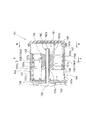
- FIG. 2 is a partially enlarged view of the dynamic vibration absorber 151 in FIG. 3 is a diagram showing a cross-sectional structure taken along line AA of the dynamic vibration absorber 151 in FIG. 2
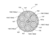
- FIG. 4 is a diagram showing a cross-sectional structure taken along line BB of the dynamic vibration absorber 151 in FIG. is there.
- the electric hammer drill 101 is generally viewed as a main body 103 that forms an outline of the hammer drill 101, and a tip region in the major axis direction of the main body 103 (see FIG. 1).
- the tool holder 137 connected to the middle left), the long-axis hammer bit 119 detachably attached to the tool holder 137, the other end of the main body 103 in the long-axis direction (the right side in the figure), particularly the main body
- the part 103 is mainly composed of a tool gripping hand grip 105 connected to a tool rear end side of a drive motor 111 described later.
- the hammer bit 119 is capable of relative reciprocation in the major axis direction (major axis direction of the main body 103) with respect to the tool holder 137, and relative rotation in the circumferential direction is restricted. It is configured as a member held in a state.
- the main body 103, the hammer bit 119, and the handgrip 105 here constitute the “tool main body”, “tip tool”, and “handle portion” in the present invention, respectively.
- the hammer bit 119 side is referred to as the front or tool front end side
- the handgrip 105 side is referred to as the rear or tool rear end side.
- the main body 103 is configured as a housing that houses a drive motor 111, a motion conversion mechanism 113, a striking element 115, a power transmission mechanism 117, and a dynamic vibration absorber 151.
- this main-body part 103 may be comprised by the combination of the separate housing which accommodates one or more of said to-be-accepted elements.
- the rotational output of the drive motor 111 is appropriately converted into a linear motion by the motion conversion mechanism 113 and then transmitted to the striking element 115, and the long axis direction of the hammer bit 119 (through the striking element 115 ( An impact force in the horizontal direction in FIG. 1 is generated.
- this hammer drill 101 provided with the striking element 115 is also referred to as a striking tool.
- the rotation output of the drive motor 111 is appropriately decelerated by the power transmission mechanism 117 and then transmitted as a rotational force to the hammer bit 119, and the hammer bit 119 is rotated in the circumferential direction.
- the drive motor 111 here corresponds to the “drive motor” in the present invention.
- the motion conversion mechanism 113 converts the rotational motion of the motor shaft 111a of the drive motor 111 into a linear motion and transmits it to the striking element 115, and is driven by gear meshing engagement with the motor shaft 111a of the drive motor 111.
- a crank mechanism including a crankshaft 121, a crank arm 123, a piston 125, and the like.
- the crankshaft 121 includes a crankshaft 121a and an eccentric pin 121b that is eccentrically provided on the crankshaft 121a.
- One end of the crank arm 123 is connected to the eccentric pin 121b of the crankshaft 121, and the other end is connected to the piston 125.
- the piston 125 constitutes a driver for driving the so-called striking element 115, and can slide in the cylinder 141 in the same direction as the major axis direction of the hammer bit 119.
- the motion conversion mechanism 113 is disposed on the tool front end side with respect to the longitudinal direction of the hammer bit 119 relative to the drive motor 111. More specifically, the crankshaft 121a and the eccentric pin 121b of the crankshaft 121 in each part of the motion conversion mechanism 113 are arranged on the tool front end side with respect to the long axis direction of the hammer bit 119 relative to the motor shaft 111a of the drive motor 111. It is installed.
- the motion conversion mechanism 113 here constitutes the “motion conversion mechanism” in the present invention.
- the striking element 115 is slidably disposed on the striker 143 slidably disposed on the bore inner wall of the cylinder 141 and the tool holder 137, and transmits the kinetic energy of the striker 143 to the hammer bit 119. And an impact bolt 145 as an intermediate element.
- the striking element 115 here corresponds to the “striking element” in the present invention.
- An air chamber 141 a that is closed between the piston 125 and the striker 143 is formed in the cylinder 141.
- the striker 143 is driven by the principle of a so-called “air spring” using the air in the air chamber 141 a of the cylinder 141 that accompanies the sliding movement of the piston 125, and serves as an intermediate element slidably disposed on the tool holder 137.
- the impact bolt 145 collides (hits), and the impact force is transmitted to the hammer bit 119 via the impact bolt 145.
- the crank chamber 165 that accommodates the crankshaft 121 and the crank arm 123 has a phase opposite to that of the air pressure fluctuation of the air chamber 141a. It is configured as a space that generates air pressure fluctuations. That is, when the striking element 115 strikes the hammer bit 119, the crank chamber 165 has a relatively low pressure in a state in which the air chamber 141a has a relatively high pressure, while the air chamber 141a has a relative pressure after the end of the striking.
- the air pressure fluctuation pattern is substantially reversed between the air chamber 141a and the crank chamber 165 so that the crank chamber 165 has a relatively high pressure.
- the air chamber 141a here corresponds to the “first space” in the present invention
- the crank chamber 165 here corresponds to the “second space” in the present invention.
- the tool holder 137 is configured to be rotatable, and is configured to be rotated at a reduced speed from the drive motor 111 via the power transmission mechanism 117.
- the power transmission mechanism 117 is an intermediate gear 131 that is rotationally driven by the drive motor 111, a small bevel gear 133 that rotates together with the intermediate gear 131, and a large bevel gear that meshes with and engages with the small bevel gear 133 and rotates about the major axis of the main body 103.
- the rotation of the drive motor 111 is transmitted to the tool holder 137 and further transmitted to the hammer bit 119 held by the tool holder 137.
- the hammer drill 101 applies a striking force in the major axis direction to the hammer bit 119 so as to process the workpiece, so-called hammering work, a striking force in the major axis direction, and a rotational force in the circumferential direction.
- a so-called hammer drilling operation is performed so as to perform the processing operation of the workpiece by appropriately switching, but since this is not directly related to the present invention, the description thereof will be given. Omitted.
- shock and periodic vibration in the long axis direction of the hammer bit occurs in the main body 103.
- the main vibration as a vibration suppression target generated in the main body 103 is the compression reaction force when the piston 125 and the striker 143 compress the air in the air chamber 141a, and the striker 143 causes the hammer bit 119 to pass through the impact bolt 145. This is a striking reaction force generated slightly after the compression reaction force when striking.
- the hammer drill 101 is configured to include a dynamic vibration absorber 151 to suppress the vibration generated in the main body 103.
- the dynamic vibration absorber 151 is disposed on the dynamic vibration absorber main body 153, the vibration damping weight 155, and the front end side and the rear end side of the weight 155, respectively.
- the coil spring 157 is mainly composed of front and rear coil springs 157 extending in the direction.
- the dynamic vibration absorber main body 153 has a hollow or cylindrical housing space, and is provided as a cylindrical guide portion that allows the weight 155 to slide stably.
- the dynamic vibration absorber main body 153 here corresponds to the “dynamic vibration absorber main body” in the present invention.
- this intermediate region is a region between the crankshaft 121a and the eccentric pin 121b of the crankshaft 121 and the handgrip 105, and the tool upper end side of the motor shaft 111a of the drive motor 111 (FIG. 1). It is defined as the upper (middle) area. Therefore, in the present embodiment, the dynamic vibration absorber main body 153 is disposed in this intermediate region between the motion conversion mechanism 113 and the hand grip 105. Accordingly, it is not necessary to form a new arrangement space for arranging the dynamic vibration absorber main body 153, and the space in the main body portion 103 can be used effectively, so that the rational arrangement of the dynamic vibration absorber 151 can be achieved. Is possible.
- This intermediate region between the motion conversion mechanism 113 and the handgrip 105 is preferably arranged closer to the long axis of the hammer bit 119 or on the extended line of the long axis of the hammer bit 119.
- the weight 155 is configured as a mass portion that is slidably disposed in the accommodation space of the dynamic vibration absorber body 153 so as to move in the long axis direction (long axis direction of the hammer bit 119) in the accommodation space of the dynamic vibration absorber body 153.
- the Specifically, the weight 155 is configured as a weight member having a circular cross section in the direction intersecting the long axis direction of the hammer bit 119.
- the weight 155 here corresponds to a “weight” and a “weight member” in the present invention.
- the coil spring 157 applies the elastic force opposite to the weight 155. It is configured as an elastic body that supports the weight 155.
- the coil spring 157 here corresponds to the “coil spring” in the present invention.
- the dynamic vibration absorber 151 having the above-described configuration housed in the main body 103 has a weight 155 and a coil spring that are vibration damping elements in the dynamic vibration absorber 151 with respect to the main body 103 that is the object of vibration suppression when the hammer drill 101 is processed. 157 cooperate to perform passive vibration suppression. As a result, the vibration generated in the main body portion 103 of the hammer drill 101 is suppressed, and the main body portion 103 is suppressed during processing.
- the weight 155 configured as described above has a spring housing space 156 having an annular cross section extending in a concave shape in the major axis direction over a predetermined region on the front end side and the rear end side in the major axis direction of the hammer bit 119.
- This spring accommodating space 156 one end portion of the coil spring 157 is accommodated.
- the spring accommodating space 156 here corresponds to the “spring accommodating portion” in the present invention.
- Each annular spring accommodating space 156 is a space portion extending in the longitudinal direction in the long axis direction of the hammer bit 119, and has an outer cylindrical tubular portion 155a and a cylindrical shape inside the tubular portion 155a. It is configured as a hollow space (groove) surrounded by the columnar portion 155b.
- the cylindrical portion 155a and the columnar portion 155b may have a separate structure or an integral structure.
- a total of six spring accommodating spaces 156 are arranged on the same plane with respect to the direction intersecting the major axis direction of the hammer bit 119.
- these six spring accommodating spaces 156 include three first spring accommodating spaces 156 a formed on the front end side of the weight 155 (the left region of the weight 155 in FIG. 2), and the weight 155.
- Three second spring accommodating spaces 156b formed on the rear end side (the right region of the weight 155 in FIG. 2) are arranged alternately and at equal intervals in the circumferential direction of the weight 155.
- Each coil spring 157 housed in each spring housing space 156 is fixed in such a manner that the spring front end 157a is attached and fixed to the spring front end fastening portion 158, and the spring rear end 157b is attached to the spring rear end fastening portion 159.
- the first spring accommodating space 156a here corresponds to the “front side spring accommodating portion” in the present invention
- the second spring accommodating space 156b here corresponds to the “rear side spring accommodating portion” in the present invention.
- the plurality of spring accommodating portions 156 are arranged in a balanced manner on the front side and the rear side of the weight 155, it is easy to balance the center of gravity of the weight 155.
- the elastic force of the plurality of coil springs can be applied to the front side and the rear side of the weight 155 in a balanced manner.
- the front wall portion of the dynamic vibration absorber body 153 is used as the spring front end fixing portion 158 to which the spring front end 157a is attached and fixed.
- the spring rear end fastening portion 159 to which the rear end 157b is attached and fixed the bottom portion (terminal portion) of the first spring accommodating space 156a is used.
- the bottom portion (terminal portion) of the second spring housing space 156b is used as the spring front end fastening portion 158 to which the spring front end 157a is attached and fixed.
- the rear wall portion of the dynamic vibration absorber body 153 is used as the spring rear end fastening portion 159 to which the spring rear end 157b is attached and fixed.
- the front and rear coil springs 157 cause an elastic biasing force in the major axis direction of the hammer bit 119 to act on the weight 155 in an opposing manner.
- the weight 155 is movable in the major axis direction of the hammer bit 119 in a state where the elastic biasing force of the front and rear coil springs 157 acts in an opposing manner.
- the first spring accommodating space 156a and the second spring accommodating space 156b are both formed wider than the wire diameter of the coil spring 157, whereby the coil spring 157 is formed on the inner surface of the cylindrical portion 155a and the columnar portion 155b. It is preferable to arrange it loosely so as not to contact the outer surface.
- the dynamic vibration absorber 151 has a structure in which the spring accommodating space 156 is formed inside the weight 155 and one end of the coil spring 157 is disposed in the spring accommodating space 156.
- the length of the hammer bit 119 of the dynamic vibration absorber 151 in a state in which the coil spring 157 is housed and assembled in the spring housing space 156 of the weight 155 can be suppressed. It is possible to reduce the size of the vibration absorber 151.
- the cylindrical portion 155a having a mass higher in density than the coil spring 157 is disposed on the outer peripheral side of the coil spring 157.
- the weight 155 it is possible to increase the mass of the weight 155 as a damping element, and the space utilization efficiency is improved, as compared with the conventional configuration in which a coil spring having a density lower than that of the weight is arranged on the outer peripheral side of the weight. As a result, the vibration damping force of the dynamic vibration absorber 151 can be increased. Further, by arranging the cylindrical portion 155a of the weight 155 on the outer periphery of the coil spring 157, the contact length in the moving direction of the weight 155 with respect to the wall surface of the dynamic vibration absorber main body 153, that is, the axial length of the sliding surface is increased. Therefore, stable operation of the weight 155 can be easily ensured.
- the first spring accommodating spaces 156a and the second spring accommodating spaces 156b are disposed so as to partially overlap.
- the coil spring 157 accommodated in the first spring accommodating space 156a and the coil spring 157 accommodated in the second spring accommodating space 156b are partially in the direction intersecting the extending direction of these coil springs.
- the dynamic vibration absorber 151 is disposed in the main body portion 103, it is particularly effective when the arrangement space in the major axis direction of the main body portion 103 is restricted.
- the coil spring 157 housed in the first spring housing space 156a and the coil spring 157 housed in the second spring housing space 156b partially overlap, the dynamic vibration absorber having the same dimension in the major axis direction is considered.
- the coil spring can be further increased in size, and high vibration damping can be stably imparted by the increased coil spring.
- the dynamic vibration absorber 151 can be made compact (downsized) after the vibration damping force of the dynamic vibration absorber 151 is increased.
- the vibration reduction effect of the dynamic vibration absorber 151 can be enhanced by a minimum weight increase without increasing the size of the 103.
- the dynamic vibration absorber 151 includes a first working chamber 161 and a second working chamber 163 in the dynamic vibration absorber body 153.
- the first working chamber 161 and the second working chamber 163 are defined by a weight 155 in the dynamic vibration absorber body 153, and are configured as a space portion formed before and after the weight 155 with respect to the longitudinal direction of the hammer bit 119. Is done.
- the first working chamber 161 is configured as a space behind the weight 155 (left side in FIG. 2).
- the first working chamber 161 is always in communication with the crank chamber 165 having a sealed structure that is not in communication with the outside through the first communication hole 162a of the communication pipe 162.
- the second working chamber 163 communicates with a gear chamber 164 in which the motor shaft 111a of the drive motor 111 is disposed through a second communication hole 163a formed in the outer peripheral wall of the dynamic vibration absorber body 153.
- the first working chamber 161 and the second working chamber 163 here correspond to the “rear chamber” and the “front chamber” in the present invention, respectively.
- the pressure in the crank chamber 165 fluctuates as the motion conversion mechanism 113 is driven. This is based on the fact that the volume of the crank chamber 165 changes as the piston 125, which is a constituent member of the motion conversion mechanism 113, linearly moves in the front-rear direction in the cylinder 141. Therefore, in the present embodiment, the air in the crank chamber 165 is introduced into the first working chamber 161 in accordance with the pressure fluctuation in the crank chamber 165, and the weight 155 of the dynamic vibration absorber 151 is actively driven. The dynamic vibration absorber 151 is caused to perform a vibration damping action.
- the dynamic vibration absorber body 153 is provided with a communication pipe 162 having a first communication hole 162a as shown in FIG.
- the dynamic vibration absorber 151 also acts as an active vibration damping mechanism by forced vibration that actively drives the weight 155 in addition to the above-described passive vibration damping action.
- the generated vibration is more effectively suppressed.
- the communication pipe 162 is configured as a piping member that extends in a straight line in the long axis direction of the hammer bit 119, and the second operation is performed from a crank chamber 165 disposed on the tool front end side with respect to the dynamic vibration absorber body 153. After sequentially passing through the chamber 163 and the weight 155, the first working chamber 161 is disposed. According to such a configuration, it is possible to realize an arrangement form of the communication pipe 162 that allows the crank chamber 165 and the first working chamber 161 to communicate with each other at the shortest distance.
- the communication pipe 162 is configured to extend linearly in the major axis direction of the hammer bit 119 and to penetrate the center of the cross-sectional circle of each part of the weight 155.
- the outer surface 162b of the communication tube 162 and the inner surface 155c of the weight 155 penetrating the communication tube 162 are in sliding contact with each other, whereby the communication tube 162 performs linear motion in the major axis direction of the weight 155. It is comprised as a guide member to guide.
- the linear movement in the major axis direction of the weight 155 is smoothed, and the communication pipe 162 has a function of introducing the air in the crank chamber 165 into the first working chamber 161 of the dynamic vibration absorber 151.
- the function as a guide member for guiding the linear movement of the weight 155 in the major axis direction can be given, which is reasonable.
- the air When air flows between the crank chamber 165 and the first working chamber 161 through the first communication hole 162a of the communication pipe 162, the air is communicated with the gear chamber 164 according to the pressure of the first working chamber 161.
- the volume of the second working chamber 163 changes. Specifically, when the pressure in the first working chamber 161 is relatively high, the volume of the second working chamber 163 decreases while the air in the second working chamber 163 flows out to the gear chamber 164, while the first working chamber 163 decreases. When the pressure of 161 becomes relatively low, the volume of the second working chamber 163 increases while the air in the gear chamber 164 flows into the second working chamber 163. As a result, the forced excitation that actively drives the weight 155 is smoothly performed without being obstructed by the air in the second working chamber 163.
- the recessed spring accommodating spaces 156 are provided on the front end side and the rear end side of the weight 155, and one end of the coil spring 157 is accommodated in the spring accommodating space 156.
- a structure in which one end portion of the coil spring 157 is fixed to the front end side and the rear end side of the weight 155 without providing the spring accommodating space 156 in the weight 155 can be adopted.
- the spring accommodating space 156 or the fastening portion of the coil spring 157 can be provided on at least one of the front end side and the rear end side of the weight 155 as necessary.
- the three first spring accommodating spaces 156a formed on the front end side of the weight 155 and the three second spring accommodating spaces 156b formed on the rear end side of the weight 155 are the weight 155.
- the arrangement of the first spring accommodating spaces 156a on the front end side of the weight 155 and the first arrangement on the rear end side of the weight 155 are described.
- the arrangement of the two spring accommodating spaces 156b can be changed as appropriate.
- the communication pipe 162 extends from the crank chamber 165 to the second working chamber 163.
- a structure other than this can be selected as the structure of the communication pipe 162.
- a member corresponding to the communication pipe 162 may be disposed so as to communicate with the first working chamber 161 from the crank chamber 165 via the outside of the dynamic vibration absorber body 153 of the dynamic vibration absorber 151.
- the communication pipe 162 is also used as a guide member that guides the linear motion of the weight 155 in the major axis direction.
- a member corresponding to the communication pipe 162 is used. Otherwise, the guide function of the weight 155 may be achieved.
- the hammer drill 101 is described as an example of the work tool.
- the present invention is applied to various work tools that perform the work of processing the workpiece by moving the tip tool linearly.
- the invention can be applied.
- the present invention can be suitably used for a jigsaw or a reciprocating saw that cuts a workpiece by moving a saw blade back and forth linearly.
- FIG. 3 is a view showing a cross-sectional structure of the dynamic vibration absorber 151 in FIG.
- FIG. 3 is a view showing a cross-sectional structure of the dynamic vibration absorber 151 in FIG.
Landscapes
- Engineering & Computer Science (AREA)
- Mechanical Engineering (AREA)
- Percussive Tools And Related Accessories (AREA)
Abstract
Priority Applications (4)
| Application Number | Priority Date | Filing Date | Title |
|---|---|---|---|
| EP09766619.2A EP2301719B1 (fr) | 2008-06-19 | 2009-06-15 | Outil de travail |
| CN200980123024.3A CN102066056B (zh) | 2008-06-19 | 2009-06-15 | 作业工具 |
| RU2011101689/02A RU2505390C2 (ru) | 2008-06-19 | 2009-06-15 | Электроинструмент |
| US12/999,208 US8668026B2 (en) | 2008-06-19 | 2009-06-15 | Power tool comprising a dynamic vibration reducer |
Applications Claiming Priority (2)
| Application Number | Priority Date | Filing Date | Title |
|---|---|---|---|
| JP2008161027A JP5214343B2 (ja) | 2008-06-19 | 2008-06-19 | 作業工具 |
| JP2008-161027 | 2008-06-19 |
Publications (1)
| Publication Number | Publication Date |
|---|---|
| WO2009154171A1 true WO2009154171A1 (fr) | 2009-12-23 |
Family
ID=41434087
Family Applications (1)
| Application Number | Title | Priority Date | Filing Date |
|---|---|---|---|
| PCT/JP2009/060879 WO2009154171A1 (fr) | 2008-06-19 | 2009-06-15 | Outil de travail |
Country Status (6)
| Country | Link |
|---|---|
| US (1) | US8668026B2 (fr) |
| EP (1) | EP2301719B1 (fr) |
| JP (1) | JP5214343B2 (fr) |
| CN (1) | CN102066056B (fr) |
| RU (1) | RU2505390C2 (fr) |
| WO (1) | WO2009154171A1 (fr) |
Cited By (1)
| Publication number | Priority date | Publication date | Assignee | Title |
|---|---|---|---|---|
| EP2415565A1 (fr) * | 2010-08-03 | 2012-02-08 | Makita Corporation | Machine-outil |
Families Citing this family (14)
| Publication number | Priority date | Publication date | Assignee | Title |
|---|---|---|---|---|
| JP5336781B2 (ja) * | 2008-07-07 | 2013-11-06 | 株式会社マキタ | 作業工具 |
| US9981372B2 (en) | 2012-12-31 | 2018-05-29 | Robert Bosch Tool Corporation | Reciprocating tool with fluid driven counterweight |
| US9573207B2 (en) * | 2013-05-09 | 2017-02-21 | Makita Corporation | Reciprocating cutting tool |
| JP6179270B2 (ja) * | 2013-08-22 | 2017-08-16 | アイシン精機株式会社 | 車両用ドア開閉装置 |
| EP2942158A1 (fr) * | 2014-05-09 | 2015-11-11 | HILTI Aktiengesellschaft | Machine-outil portative |
| EP3028820A1 (fr) | 2014-12-03 | 2016-06-08 | HILTI Aktiengesellschaft | Machine-outils portative et procédé de commande associé |
| EP3028821A1 (fr) * | 2014-12-03 | 2016-06-08 | HILTI Aktiengesellschaft | Procédé de contrôle pour une machine-outils portative |
| US20160340849A1 (en) * | 2015-05-18 | 2016-11-24 | M-B-W, Inc. | Vibration isolator for a pneumatic pole or backfill tamper |
| JP6579197B2 (ja) * | 2015-11-26 | 2019-09-25 | 工機ホールディングス株式会社 | 往復動作業機 |
| US10864609B2 (en) * | 2017-09-28 | 2020-12-15 | Makita Corporation | Dust collector |
| US10814468B2 (en) | 2017-10-20 | 2020-10-27 | Milwaukee Electric Tool Corporation | Percussion tool |
| EP4349534A2 (fr) | 2018-01-26 | 2024-04-10 | Milwaukee Electric Tool Corporation | Outil à percussion |
| CN215617869U (zh) | 2018-04-04 | 2022-01-25 | 米沃奇电动工具公司 | 一种适于向工具头施加轴向冲击的旋转锤 |
| US11400577B2 (en) * | 2019-06-11 | 2022-08-02 | Makita Corporation | Impact tool |
Citations (3)
| Publication number | Priority date | Publication date | Assignee | Title |
|---|---|---|---|---|
| JP2004154903A (ja) | 2002-11-07 | 2004-06-03 | Makita Corp | 作業工具 |
| JP2007237301A (ja) * | 2006-03-07 | 2007-09-20 | Hitachi Koki Co Ltd | 電動工具 |
| JP2007237304A (ja) * | 2006-03-07 | 2007-09-20 | Hitachi Koki Co Ltd | 打撃工具 |
Family Cites Families (12)
| Publication number | Priority date | Publication date | Assignee | Title |
|---|---|---|---|---|
| US2875731A (en) * | 1956-03-23 | 1959-03-03 | Buckeye Steel Castings Co | Vibration absorbers for reciprocating tools |
| SU550507A1 (ru) | 1975-08-13 | 1977-03-15 | Предприятие П/Я А-1698 | Амортизирующее устройство с регулируемой жесткостью |
| DE3122979A1 (de) * | 1981-06-10 | 1983-01-05 | Hilti AG, 9494 Schaan | Bohr- oder meisselhammer |
| JP3424870B2 (ja) * | 1995-02-28 | 2003-07-07 | 株式会社マキタ | 打撃工具の空打ち防止装置 |
| CN1422730A (zh) * | 2001-12-06 | 2003-06-11 | 陈秀如 | 气动工具的减震装置 |
| DE10254813A1 (de) * | 2002-11-23 | 2004-06-03 | Hilti Ag | Elektrohandwerkzeugmaschine mit schwingungsentkoppelter Schlagwerksbaugruppe |
| JP4195818B2 (ja) * | 2003-01-16 | 2008-12-17 | 株式会社マキタ | 電動ハンマ |
| EP1464449B1 (fr) * | 2003-04-01 | 2010-03-24 | Makita Corporation | Outil électrique |
| EP1618999B1 (fr) | 2004-07-14 | 2008-06-25 | AEG Electric Tools GmbH | marteau perforateur et/ou marteau-burineur |
| JP4647957B2 (ja) * | 2004-08-27 | 2011-03-09 | 株式会社マキタ | 作業工具 |
| JP4815119B2 (ja) | 2004-10-15 | 2011-11-16 | 株式会社マキタ | 往復作動式作業工具 |
| US7806201B2 (en) | 2007-07-24 | 2010-10-05 | Makita Corporation | Power tool with dynamic vibration damping |
-
2008
- 2008-06-19 JP JP2008161027A patent/JP5214343B2/ja active Active
-
2009
- 2009-06-15 EP EP09766619.2A patent/EP2301719B1/fr active Active
- 2009-06-15 CN CN200980123024.3A patent/CN102066056B/zh active Active
- 2009-06-15 WO PCT/JP2009/060879 patent/WO2009154171A1/fr active Application Filing
- 2009-06-15 US US12/999,208 patent/US8668026B2/en active Active
- 2009-06-15 RU RU2011101689/02A patent/RU2505390C2/ru active
Patent Citations (3)
| Publication number | Priority date | Publication date | Assignee | Title |
|---|---|---|---|---|
| JP2004154903A (ja) | 2002-11-07 | 2004-06-03 | Makita Corp | 作業工具 |
| JP2007237301A (ja) * | 2006-03-07 | 2007-09-20 | Hitachi Koki Co Ltd | 電動工具 |
| JP2007237304A (ja) * | 2006-03-07 | 2007-09-20 | Hitachi Koki Co Ltd | 打撃工具 |
Non-Patent Citations (1)
| Title |
|---|
| See also references of EP2301719A4 |
Cited By (4)
| Publication number | Priority date | Publication date | Assignee | Title |
|---|---|---|---|---|
| EP2415565A1 (fr) * | 2010-08-03 | 2012-02-08 | Makita Corporation | Machine-outil |
| CN102343577A (zh) * | 2010-08-03 | 2012-02-08 | 株式会社牧田 | 作业工具 |
| US8844647B2 (en) | 2010-08-03 | 2014-09-30 | Makita Corporation | Power tool |
| RU2577639C2 (ru) * | 2010-08-03 | 2016-03-20 | Макита Корпорейшн | Приводной инструмент |
Also Published As
| Publication number | Publication date |
|---|---|
| EP2301719A1 (fr) | 2011-03-30 |
| CN102066056B (zh) | 2014-05-07 |
| US20110155405A1 (en) | 2011-06-30 |
| RU2505390C2 (ru) | 2014-01-27 |
| JP5214343B2 (ja) | 2013-06-19 |
| JP2010000564A (ja) | 2010-01-07 |
| CN102066056A (zh) | 2011-05-18 |
| EP2301719B1 (fr) | 2015-08-05 |
| RU2011101689A (ru) | 2012-07-27 |
| US8668026B2 (en) | 2014-03-11 |
| EP2301719A4 (fr) | 2011-12-14 |
Similar Documents
| Publication | Publication Date | Title |
|---|---|---|
| JP5214343B2 (ja) | 作業工具 | |
| JP5336781B2 (ja) | 作業工具 | |
| JP6096593B2 (ja) | 往復動式作業工具 | |
| US8016047B2 (en) | Electrical power tool with anti-vibration mechanisms of different types | |
| JP5128998B2 (ja) | 手持式作業工具 | |
| JP5290666B2 (ja) | 打撃工具 | |
| JP4659737B2 (ja) | 作業工具 | |
| US8240395B2 (en) | Hand-held power tool | |
| JP7080606B2 (ja) | 作業工具 | |
| JP5496812B2 (ja) | 作業工具 | |
| WO2013111460A1 (fr) | Outil de frappe | |
| JP5294726B2 (ja) | 手持式作業工具 | |
| WO2007105742A1 (fr) | Outil mécanique électrique | |
| JP5147449B2 (ja) | 作業工具 | |
| JP4815119B2 (ja) | 往復作動式作業工具 | |
| JP2007175836A (ja) | 打撃工具 | |
| WO2015166995A1 (fr) | Outil de travail | |
| JP7365197B2 (ja) | 往復動工具 | |
| JP4757043B2 (ja) | 作業工具 | |
| JP2007175837A (ja) | 打撃工具 | |
| JP2016140934A (ja) | 動力工具 | |
| JP2010052118A (ja) | 打撃工具 | |
| JP2012232371A (ja) | 打撃工具 |
Legal Events
| Date | Code | Title | Description |
|---|---|---|---|
| WWE | Wipo information: entry into national phase |
Ref document number: 200980123024.3 Country of ref document: CN |
|
| 121 | Ep: the epo has been informed by wipo that ep was designated in this application |
Ref document number: 09766619 Country of ref document: EP Kind code of ref document: A1 |
|
| NENP | Non-entry into the national phase |
Ref country code: DE |
|
| WWE | Wipo information: entry into national phase |
Ref document number: 2009766619 Country of ref document: EP |
|
| WWE | Wipo information: entry into national phase |
Ref document number: 2011101689 Country of ref document: RU |
|
| WWE | Wipo information: entry into national phase |
Ref document number: 12999208 Country of ref document: US |