WO2009145093A1 - スパッタリング方法 - Google Patents
スパッタリング方法 Download PDFInfo
- Publication number
- WO2009145093A1 WO2009145093A1 PCT/JP2009/059275 JP2009059275W WO2009145093A1 WO 2009145093 A1 WO2009145093 A1 WO 2009145093A1 JP 2009059275 W JP2009059275 W JP 2009059275W WO 2009145093 A1 WO2009145093 A1 WO 2009145093A1
- Authority
- WO
- WIPO (PCT)
- Prior art keywords
- output
- switching
- targets
- target
- power
- Prior art date
- Legal status (The legal status is an assumption and is not a legal conclusion. Google has not performed a legal analysis and makes no representation as to the accuracy of the status listed.)
- Ceased
Links
Images

Classifications
-
- H—ELECTRICITY
- H01—ELECTRIC ELEMENTS
- H01J—ELECTRIC DISCHARGE TUBES OR DISCHARGE LAMPS
- H01J37/00—Discharge tubes with provision for introducing objects or material to be exposed to the discharge, e.g. for the purpose of examination or processing thereof
- H01J37/32—Gas-filled discharge tubes
- H01J37/34—Gas-filled discharge tubes operating with cathodic sputtering
-
- C—CHEMISTRY; METALLURGY
- C23—COATING METALLIC MATERIAL; COATING MATERIAL WITH METALLIC MATERIAL; CHEMICAL SURFACE TREATMENT; DIFFUSION TREATMENT OF METALLIC MATERIAL; COATING BY VACUUM EVAPORATION, BY SPUTTERING, BY ION IMPLANTATION OR BY CHEMICAL VAPOUR DEPOSITION, IN GENERAL; INHIBITING CORROSION OF METALLIC MATERIAL OR INCRUSTATION IN GENERAL
- C23C—COATING METALLIC MATERIAL; COATING MATERIAL WITH METALLIC MATERIAL; SURFACE TREATMENT OF METALLIC MATERIAL BY DIFFUSION INTO THE SURFACE, BY CHEMICAL CONVERSION OR SUBSTITUTION; COATING BY VACUUM EVAPORATION, BY SPUTTERING, BY ION IMPLANTATION OR BY CHEMICAL VAPOUR DEPOSITION, IN GENERAL
- C23C14/00—Coating by vacuum evaporation, by sputtering or by ion implantation of the coating forming material
- C23C14/22—Coating by vacuum evaporation, by sputtering or by ion implantation of the coating forming material characterised by the process of coating
- C23C14/34—Sputtering
- C23C14/3464—Sputtering using more than one target
-
- H—ELECTRICITY
- H01—ELECTRIC ELEMENTS
- H01J—ELECTRIC DISCHARGE TUBES OR DISCHARGE LAMPS
- H01J37/00—Discharge tubes with provision for introducing objects or material to be exposed to the discharge, e.g. for the purpose of examination or processing thereof
- H01J37/32—Gas-filled discharge tubes
- H01J37/34—Gas-filled discharge tubes operating with cathodic sputtering
- H01J37/3411—Constructional aspects of the reactor
- H01J37/3414—Targets
- H01J37/3426—Material
- H01J37/3429—Plural materials
-
- H—ELECTRICITY
- H01—ELECTRIC ELEMENTS
- H01J—ELECTRIC DISCHARGE TUBES OR DISCHARGE LAMPS
- H01J37/00—Discharge tubes with provision for introducing objects or material to be exposed to the discharge, e.g. for the purpose of examination or processing thereof
- H01J37/32—Gas-filled discharge tubes
- H01J37/34—Gas-filled discharge tubes operating with cathodic sputtering
- H01J37/3411—Constructional aspects of the reactor
- H01J37/3444—Associated circuits
Definitions
- the present invention relates to a sputtering method for forming a predetermined thin film on the surface of a processing substrate such as glass, and more particularly to a sputtering method for sputtering each target by supplying power in a bipolar pulse shape for each pair of targets.
- sputtering As a method for efficiently forming a thin film on a large area processing substrate by sputtering (hereinafter referred to as “sputtering”), a plurality of targets are arranged in parallel in a vacuum chamber so as to face the processing substrate.
- a sputtering apparatus in which a plurality of bipolar pulse power sources are connected in parallel by assigning each pair of targets among the targets arranged in parallel is known. Then, while each bipolar pulse power supply is operated synchronously, the polarity is alternately changed to each target and power is input (output) in the form of a bipolar pulse, and each target is alternately switched between the anode electrode and the cathode electrode. A glow discharge is generated between them to form a plasma atmosphere, and each target is sputtered (Patent Document 1).
- the bipolar pulse power source is composed of a rectifier circuit for supplying DC power, and a MOSFET bridge circuit connected to positive and negative output terminals of the rectifier circuit and including four switching elements, and control means. Then, each switching element is appropriately operated, and a pulse voltage is applied to a pair of targets at a predetermined frequency. Accordingly, there is an advantage that the charge accumulated on the target surface is canceled when an opposite phase voltage is applied, and a stable discharge can be obtained.
- JP 2005-290550 A JP 2005-290550 A
- an object of the present invention is to provide a sputtering method that is less susceptible to switching noise by simple control, can accurately input power to a target, and thus can form a good thin film. is there.
- the sputtering method of the present invention provides a direct-current power supply source for each pair of targets among a plurality of targets arranged in parallel in a sputtering chamber and facing a processing substrate at a predetermined interval.
- the output short-circuit switching element by providing the output short-circuit switching element, it is possible to reduce the number of switching elements that are activated when the output is switched to each target, and to shift the switching timing of the output short-circuit switching element. In combination, it is possible to prevent large switching noise from occurring at the same time. As a result, even if the number of bipolar pulse power supplies connected in parallel increases, it is possible to accurately input power to each pair of targets, and a good thin film can be formed.
- switching loss can be generated by only one output short-circuit switching element, and in addition to improving the durability, switching of the output short-circuit switching element can be switched on and off. Since only the timing needs to be controlled, the control is easy.
- the control can be performed with more responsiveness than when the abnormal discharge extinguishing process is performed by controlling two switching elements in the output. Even during this process, almost no switching loss occurs in each switching element of the bridge circuit, so that the durability can be further improved.
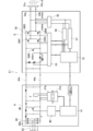
- reference numeral 1 denotes a sputtering apparatus for performing the sputtering method of the present invention.
- the sputtering apparatus 1 is of an in-line type, and has a vacuum chamber 11 that can be maintained at a predetermined degree of vacuum via a vacuum pumping means (not shown) such as a rotary pump or a turbo molecular pump, and constitutes a sputtering chamber 11a.
- a substrate transfer means 2 is provided in the upper part of the vacuum chamber 11.
- This substrate transport means 2 has a known structure, for example, has a carrier 21 on which a processing substrate S is mounted, and intermittently drives a driving means (not shown) to face the processing substrate S, which will be described later. Are transported sequentially.
- a cathode electrode C is disposed below the vacuum chamber 11.
- the cathode electrode C has eight targets 31a to 31h arranged to face the processing substrate S.
- or 31h is produced by a well-known method according to the composition of the thin film to form on the processing board
- substrate S surface such as Al, Ti, Mo, an indium and tin oxide (ITO), an alloy of indium and tin.
- ITO indium and tin oxide
- it is formed in the same shape such as a substantially rectangular parallelepiped (rectangular when viewed from above).
- Each of the targets 31a to 31h is joined to a backing plate 32 that cools the targets 31a to 31h during sputtering through a bonding material such as indium or tin, and the sputtering surface 311 when not in use is the same parallel to the processing substrate S. It is arranged in parallel at equal intervals so as to be located on a plane.
- the two targets adjacent to each other form a pair, and four bipolar pulse power sources E1 to E4 are connected to each of the targets forming a pair.
- the bipolar pulse power sources E1 to E4 have the same structure, and as shown in FIG. 2, the DC power supply unit 4 that can supply DC power and the targets 31a and 31b (31c and 31d, 31e and 31f, 31g and 31h) and an oscillating unit 5 for controlling output (power supply).
- the DC power supply unit 4 includes a first CPU circuit 41 that controls its operation, an input unit 42 to which commercial AC power (three-phase AC 200 V or 400 V) is input, and rectifies the input AC power to generate a DC
- the rectifier circuit 43 includes six diodes 43a that convert electric power, and outputs DC power to the oscillating unit 5 through positive and negative DC power lines 44a and 44b.
- the DC power supply unit 4 is connected to a switching transistor 45 provided between the DC power lines 44a and 44b and the first CPU circuit 11 so as to be communicable, and an output oscillation for controlling on / off of the switching transistor 45.
- Driver circuit 46 is provided.
- a detection circuit 47a for detecting the current and voltage is connected between the DC power lines 44a and 44b, and the current and voltage detected by the detection circuit 47a are supplied to the first CPU circuit 41 via the AD conversion circuit 47b. It is designed to be entered.
- the oscillating unit 5 includes four first to fourth terminals connected between the second CPU circuit 51 communicatively connected to the first CPU circuit 41 and the positive and negative DC power lines 44a and 44b.
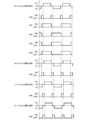
- the output oscillation driver circuit 53 switches each switching so that, for example, the on and off timings of the first and fourth switching transistors SW1 and SW4 and the second and third switching transistors SW2 and SW3 are reversed.
- power can be supplied in a bipolar pulse form to the pair of targets 31a and 31b via the output lines 54a and 54b from the bridge circuit 52.
- the waveform of the output voltage is a substantially square wave or a substantially sine wave.
- a detection circuit 55 for detecting an output current and an output voltage to the pair of targets 31a and 31b is connected to the output lines 54a and 54b.
- the output current and the output voltage detected by the detection circuit 55 are converted into an AD conversion circuit 56. To be input to the second CPU circuit 51 via.
- the switching transistors SW1 to SW4 are simultaneously switched in a state in which the DC power is output from the DC power supply unit 4, not only the switching loss becomes great, but also. There is a risk that the input power waveform to the targets 31a to 31h is disturbed by the influence of the switching noise, and favorable thin film formation is hindered.
- an output short-circuiting switching transistor SW0 whose ON / OFF switching is controlled by an output oscillation driver circuit 43 is provided between the positive and negative DC output lines 44a and 44b from the DC power supply unit 4,
- the switching transistors SW1 to SW4 of the bridge circuit 52 are switched in a short-circuit state of the output short-circuit switch transistor SW0 (a state where output to the targets 31a and 31b is blocked).
- an overall control means 6 comprising a CPU communicatively connected to the second CPU circuit 51 of each of the bipolar pulse power sources E1 to E4 is provided, and the overall control means 6 allows the output short-circuit switching element SW0 to be connected. The switching timing is shifted from each other for each bipolar pulse power source E1 to E4, that is, for each bridge circuit 52.
- the first and fourth switching transistors SW1 and SW4 are operated so that the ON and OFF timings of the second and third switching transistors SW2 and SW3 are reversed and the polarities to the targets 41a to 41h adjacent to each other are reversed. Thereafter, the short circuit of the switching transistor SW0 is released for a predetermined time by the output from the overall control means 6, and the signals are output to one of the paired targets 41a, 41c, 41e, and 41g, respectively.
- the output short-circuiting switching transistors SW0 of the bipolar pulse power supplies E1 to E4 are simultaneously or sequentially short-circuited by the output from the overall control means 6, and after switching the switching transistors SW1 to SW4, the output from the overall control means 6
- the short circuit of the switching transistor SW0 is released simultaneously or sequentially and output to the other 41b, 41d, 41f, 41h, respectively.
- electric power is supplied to each of the targets 41a to 41h in the form of a bipolar pulse at a predetermined frequency and is operated synchronously.
- the switching timing of the output short-circuit switching element When the switching timing of the output short-circuit switching element is shifted, it is sufficient that the switching timing of at least one of the output short-circuit switching transistors SW0 of the bipolar pulse power supplies E1 to E4 is shifted.
- the output short-circuiting switching transistors SW0 may be shifted simultaneously or with respect to each other. Further, for example, the output short-circuit switching transistors SW0 of the bipolar pulse power supplies E1 to E4 may be divided into a plurality of sets, and the sets may be switched simultaneously.
- the output short-circuit switching transistor SW0 is provided, the number of switching elements that operate when the output is switched to each of the targets 31a to 31h is reduced, and the switching timing of the output short-circuit switching transistor SW0 is set for each bridge circuit 52. It is possible to prevent large switching noise from occurring at the same time due to the mutual shifting. As a result, even when the number of bipolar pulse power supplies E1 to E4 connected in parallel is large, it is possible to accurately supply power to each pair of targets 31a to 31h, and it is possible to form a favorable thin film.
- the oscillation unit 5 configured separately from the power supply unit 4 is provided close to the vacuum chamber 11, and the output terminal of the bridge circuit 52 and the targets 31a to 31a. It is desirable to use a bus bar as the output lines 54a and 54b connecting the terminal 31h.
- the bus bar is made of a material having high conductivity, for example, Cu, Au, Ag, or an aluminum alloy, and is formed to be stretchable so as to absorb an error in the distance between the oscillation unit 5 and the targets 31a to 31h. Yes.
- the carrier 21 on which the processing substrate S is set by the substrate transport means 2 is transported to a position facing the targets 31a to 31h arranged in parallel, and a gas (not shown) under a predetermined pressure (for example, 10 ⁇ 5 Pa).
- Sputtering gas or reaction gas
- a gas for example, 10 ⁇ 5 Pa.
- Sputtering gas or reaction gas
- the targets 31a to 31h are alternately switched to the anode electrode and the cathode electrode.
- a glow discharge is generated between the anode electrode and the cathode electrode to form a plasma atmosphere, and each target 31a to 31h is sputtered to form a predetermined thin film on the surface of the processing substrate S.
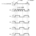
- arc discharge may occur for some reason during glow discharge as described above.
- the impedance of the plasma decreases rapidly, so that a voltage drop occurs abruptly and the current increases accordingly.
- an arc detection control circuit 57 to which the output current and output voltage detected by the detection circuit 55 are input is provided to the second CPU circuit 51 so as to be able to communicate (see FIG. 1).
- the output current changes beyond a certain range in one bipolar pulse power source E1 to E4
- it is regarded as a phenomenon before the arc discharge (micro arc) and the arc discharge process of abnormal discharge is performed by the bipolar pulse power source E1 to E4. Therefore, the occurrence of arc discharge with a large arc current is suppressed.
- the arc detection control circuit 57 captures the current state before the occurrence of arc discharge, and the second CPU circuit 51 and the arc detection control circuit 57 are used.
- the output short circuit switching transistor SW0 is short-circuited (turned on) by the output oscillation driver circuit 53.
- each of the switching transistors SW1 to SW4 of the bridge circuit 52 is connected to one of the targets 31a or 31b (31c or 31d, 31e or 31f, 31g or 31h).
- the output to the targets 31a to 31h is cut off by the switching transistor SW0 being short-circuited (micro arc process).
- the short circuit of the output short circuit switching transistor SW0 is released (turned off), and either one of the targets is switched according to the operating state of each switching transistor SW1 to SW4. Resumes output.
- the arc detection control circuit 57 determines whether or not the output current exceeds the steady output current value. If the steady output current value is still exceeded, the output oscillation driver circuit 53 causes the output short circuit switching transistor SW0 to be turned on again. Short circuit.
- FIG. 2 is a diagram schematically illustrating a configuration of a bipolar pulse power source used in the sputtering apparatus illustrated in FIG. 1.
Landscapes
- Chemical & Material Sciences (AREA)
- Engineering & Computer Science (AREA)
- Physics & Mathematics (AREA)
- Plasma & Fusion (AREA)
- Analytical Chemistry (AREA)
- Materials Engineering (AREA)
- Chemical Kinetics & Catalysis (AREA)
- Mechanical Engineering (AREA)
- Metallurgy (AREA)
- Organic Chemistry (AREA)
- Plasma Technology (AREA)
- Physical Vapour Deposition (AREA)
- Electrodes Of Semiconductors (AREA)
Priority Applications (3)
| Application Number | Priority Date | Filing Date | Title |
|---|---|---|---|
| KR1020107025302A KR101250336B1 (ko) | 2008-05-26 | 2009-05-20 | 스퍼터링 방법 |
| US12/989,438 US8404089B2 (en) | 2008-05-26 | 2009-05-20 | Sputtering method |
| CN2009801169298A CN102027154B (zh) | 2008-05-26 | 2009-05-20 | 溅射方法 |
Applications Claiming Priority (2)
| Application Number | Priority Date | Filing Date | Title |
|---|---|---|---|
| JP2008137089A JP5429771B2 (ja) | 2008-05-26 | 2008-05-26 | スパッタリング方法 |
| JP2008-137089 | 2008-05-26 |
Publications (1)
| Publication Number | Publication Date |
|---|---|
| WO2009145093A1 true WO2009145093A1 (ja) | 2009-12-03 |
Family
ID=41376972
Family Applications (1)
| Application Number | Title | Priority Date | Filing Date |
|---|---|---|---|
| PCT/JP2009/059275 Ceased WO2009145093A1 (ja) | 2008-05-26 | 2009-05-20 | スパッタリング方法 |
Country Status (6)
| Country | Link |
|---|---|
| US (1) | US8404089B2 (enExample) |
| JP (1) | JP5429771B2 (enExample) |
| KR (1) | KR101250336B1 (enExample) |
| CN (1) | CN102027154B (enExample) |
| TW (1) | TWI452160B (enExample) |
| WO (1) | WO2009145093A1 (enExample) |
Cited By (2)
| Publication number | Priority date | Publication date | Assignee | Title |
|---|---|---|---|---|
| EP2463890A1 (en) * | 2010-12-08 | 2012-06-13 | Applied Materials, Inc. | Generating plasmas in pulsed power systems |
| JP2017539066A (ja) * | 2014-12-19 | 2017-12-28 | トゥルンプフ ヒュッティンガー スプウカ ズ オグラニショナ オドポヴィヂャルノスツィアTRUMPF Huettinger Sp. z o. o. | プラズマプロセスの電力供給中に発生するアークを検出する方法、プラズマ電源のための制御ユニット、及び、プラズマ電源 |
Families Citing this family (12)
| Publication number | Priority date | Publication date | Assignee | Title |
|---|---|---|---|---|
| JP5186281B2 (ja) * | 2008-05-26 | 2013-04-17 | 株式会社アルバック | バイポーラパルス電源及びこのバイポーラパルス電源を複数台並列接続してなる電源装置 |
| JP5124344B2 (ja) * | 2008-05-26 | 2013-01-23 | 株式会社アルバック | バイポーラパルス電源及び複数のバイポーラパルス電源からなる電源装置並びに出力方法 |
| JP5124345B2 (ja) * | 2008-05-26 | 2013-01-23 | 株式会社アルバック | バイポーラパルス電源及びこのバイポーラパルス電源を複数台並列接続してなる電源装置 |
| CN103069928B (zh) * | 2010-08-18 | 2015-03-25 | 株式会社爱发科 | 直流电源装置 |
| AT513190B9 (de) * | 2012-08-08 | 2014-05-15 | Berndorf Hueck Band Und Pressblechtechnik Gmbh | Vorrichtung und Verfahren zur Plasmabeschichtung eines Substrats, insbesondere eines Pressblechs |
| DE12884110T1 (de) * | 2012-09-07 | 2015-09-24 | Kyosan Electric Mfg. Co., Ltd. | Gleichstromversorgungsvorrichtung und steuerungsverfahren für die gleichstromversorgungsvorrichtung |
| KR20140038771A (ko) * | 2012-09-21 | 2014-03-31 | 한국과학기술연구원 | 기판상에 금속박막을 증착하는 방법 |
| US9812305B2 (en) * | 2015-04-27 | 2017-11-07 | Advanced Energy Industries, Inc. | Rate enhanced pulsed DC sputtering system |
| CN105071657B (zh) * | 2015-09-11 | 2017-12-22 | 范承 | 双向可调直流电源 |
| GB2548209B (en) * | 2016-03-07 | 2018-03-21 | Intelligent Growth Solutions Ltd | Controllable power and lighting system |
| JP6966552B2 (ja) * | 2016-12-19 | 2021-11-17 | アプライド マテリアルズ インコーポレイテッドApplied Materials, Incorporated | スパッタ堆積源、スパッタ堆積装置、及び基板上に層を堆積させる方法 |
| EP3396698A1 (en) * | 2017-04-27 | 2018-10-31 | TRUMPF Hüttinger GmbH + Co. KG | Power converter unit, plasma processing equipment and method of controlling several plasma processes |
Citations (6)
| Publication number | Priority date | Publication date | Assignee | Title |
|---|---|---|---|---|
| JPH09172787A (ja) * | 1995-10-20 | 1997-06-30 | Haiden Kenkyusho:Kk | 正負パルス式高電圧電源 |
| JPH11146659A (ja) * | 1997-11-05 | 1999-05-28 | Haiden Kenkyusho:Kk | 正負パルス式スイッチング電源装置 |
| JP2005290550A (ja) * | 2004-03-11 | 2005-10-20 | Ulvac Japan Ltd | スパッタリング装置 |
| JP2006249506A (ja) * | 2005-03-10 | 2006-09-21 | National Institute For Materials Science | バイポーラパルススパッタリング成膜装置および同装置を用いて作製される薄膜材料の製造方法 |
| JP2007186726A (ja) * | 2006-01-11 | 2007-07-26 | Ulvac Japan Ltd | スパッタリング装置 |
| JP2008533687A (ja) * | 2005-03-24 | 2008-08-21 | エリコン・トレーディング・アクチェンゲゼルシャフト,トリュープバッハ | 真空プラズマ発生器 |
Family Cites Families (11)
| Publication number | Priority date | Publication date | Assignee | Title |
|---|---|---|---|---|
| DE9109503U1 (de) * | 1991-07-31 | 1991-10-17 | Magtron Magneto Elektronische Geraete Gmbh, 7583 Ottersweier | Schaltungsanordnung für ein Stromversorgungsgerät für Geräte und Anlagen der Plasma- und Oberflächentechnik |
| US5698082A (en) * | 1993-08-04 | 1997-12-16 | Balzers Und Leybold | Method and apparatus for coating substrates in a vacuum chamber, with a system for the detection and suppression of undesirable arcing |
| JP3429957B2 (ja) | 1996-08-28 | 2003-07-28 | 松下電器産業株式会社 | スパッタリング方法及び装置 |
| DE19651811B4 (de) * | 1996-12-13 | 2006-08-31 | Unaxis Deutschland Holding Gmbh | Vorrichtung zum Belegen eines Substrats mit dünnen Schichten |
| DE19702187C2 (de) * | 1997-01-23 | 2002-06-27 | Fraunhofer Ges Forschung | Verfahren und Einrichtung zum Betreiben von Magnetronentladungen |
| TWI275656B (en) * | 2002-05-31 | 2007-03-11 | Shibaura Mechatronics Corp | Power supply for discharge, power supply for sputtering, and sputtering system |
| ES2401289T3 (es) | 2005-03-24 | 2013-04-18 | Oerlikon Trading Ag, Trübbach | Generador de plasma en vacío |
| CN2873799Y (zh) * | 2005-04-08 | 2007-02-28 | 北京实力源科技开发有限责任公司 | 一种具有在线清洗功能的磁控溅射靶 |
| JP4922580B2 (ja) * | 2005-07-29 | 2012-04-25 | 株式会社アルバック | スパッタリング装置及びスパッタリング方法 |
| JP4963023B2 (ja) * | 2006-01-11 | 2012-06-27 | 株式会社アルバック | スパッタリング方法及びスパッタリング装置 |
| DE102006028977B4 (de) * | 2006-06-23 | 2012-04-12 | Qimonda Ag | Sputterdepositions-Vorrichtung |
-
2008
- 2008-05-26 JP JP2008137089A patent/JP5429771B2/ja active Active
-
2009
- 2009-05-20 KR KR1020107025302A patent/KR101250336B1/ko active Active
- 2009-05-20 US US12/989,438 patent/US8404089B2/en active Active
- 2009-05-20 CN CN2009801169298A patent/CN102027154B/zh active Active
- 2009-05-20 WO PCT/JP2009/059275 patent/WO2009145093A1/ja not_active Ceased
- 2009-05-25 TW TW098117298A patent/TWI452160B/zh active
Patent Citations (6)
| Publication number | Priority date | Publication date | Assignee | Title |
|---|---|---|---|---|
| JPH09172787A (ja) * | 1995-10-20 | 1997-06-30 | Haiden Kenkyusho:Kk | 正負パルス式高電圧電源 |
| JPH11146659A (ja) * | 1997-11-05 | 1999-05-28 | Haiden Kenkyusho:Kk | 正負パルス式スイッチング電源装置 |
| JP2005290550A (ja) * | 2004-03-11 | 2005-10-20 | Ulvac Japan Ltd | スパッタリング装置 |
| JP2006249506A (ja) * | 2005-03-10 | 2006-09-21 | National Institute For Materials Science | バイポーラパルススパッタリング成膜装置および同装置を用いて作製される薄膜材料の製造方法 |
| JP2008533687A (ja) * | 2005-03-24 | 2008-08-21 | エリコン・トレーディング・アクチェンゲゼルシャフト,トリュープバッハ | 真空プラズマ発生器 |
| JP2007186726A (ja) * | 2006-01-11 | 2007-07-26 | Ulvac Japan Ltd | スパッタリング装置 |
Cited By (4)
| Publication number | Priority date | Publication date | Assignee | Title |
|---|---|---|---|---|
| EP2463890A1 (en) * | 2010-12-08 | 2012-06-13 | Applied Materials, Inc. | Generating plasmas in pulsed power systems |
| WO2012076630A1 (en) * | 2010-12-08 | 2012-06-14 | Applied Materials Inc. | Generating plasmas in pulsed power systems |
| US8796933B2 (en) | 2010-12-08 | 2014-08-05 | Applied Materials, Inc. | Generating plasmas in pulsed power systems |
| JP2017539066A (ja) * | 2014-12-19 | 2017-12-28 | トゥルンプフ ヒュッティンガー スプウカ ズ オグラニショナ オドポヴィヂャルノスツィアTRUMPF Huettinger Sp. z o. o. | プラズマプロセスの電力供給中に発生するアークを検出する方法、プラズマ電源のための制御ユニット、及び、プラズマ電源 |
Also Published As
| Publication number | Publication date |
|---|---|
| KR101250336B1 (ko) | 2013-04-03 |
| JP5429771B2 (ja) | 2014-02-26 |
| KR20100135899A (ko) | 2010-12-27 |
| US8404089B2 (en) | 2013-03-26 |
| CN102027154B (zh) | 2012-07-18 |
| TW201006947A (en) | 2010-02-16 |
| TWI452160B (zh) | 2014-09-11 |
| CN102027154A (zh) | 2011-04-20 |
| JP2009280890A (ja) | 2009-12-03 |
| US20110036707A1 (en) | 2011-02-17 |
Similar Documents
| Publication | Publication Date | Title |
|---|---|---|
| JP5429771B2 (ja) | スパッタリング方法 | |
| JP5124345B2 (ja) | バイポーラパルス電源及びこのバイポーラパルス電源を複数台並列接続してなる電源装置 | |
| JP5429772B2 (ja) | 電源装置 | |
| JP5124344B2 (ja) | バイポーラパルス電源及び複数のバイポーラパルス電源からなる電源装置並びに出力方法 | |
| JP2009280890A5 (enExample) | ||
| JP2009284732A5 (enExample) | ||
| JP5186281B2 (ja) | バイポーラパルス電源及びこのバイポーラパルス電源を複数台並列接続してなる電源装置 | |
| KR101018652B1 (ko) | 스퍼터링 장치 | |
| TW201006317A (en) | Power source device | |
| JPWO2009025306A1 (ja) | スパッタリング方法 | |
| JP2007131896A (ja) | スパッタリング装置 |
Legal Events
| Date | Code | Title | Description |
|---|---|---|---|
| WWE | Wipo information: entry into national phase |
Ref document number: 200980116929.8 Country of ref document: CN |
|
| 121 | Ep: the epo has been informed by wipo that ep was designated in this application |
Ref document number: 09754601 Country of ref document: EP Kind code of ref document: A1 |
|
| WWE | Wipo information: entry into national phase |
Ref document number: 12989438 Country of ref document: US |
|
| ENP | Entry into the national phase |
Ref document number: 20107025302 Country of ref document: KR Kind code of ref document: A |
|
| NENP | Non-entry into the national phase |
Ref country code: DE |
|
| 122 | Ep: pct application non-entry in european phase |
Ref document number: 09754601 Country of ref document: EP Kind code of ref document: A1 |