WO2009142402A2 - Réseau de radiocommunications - Google Patents
Réseau de radiocommunications Download PDFInfo
- Publication number
- WO2009142402A2 WO2009142402A2 PCT/KR2009/002415 KR2009002415W WO2009142402A2 WO 2009142402 A2 WO2009142402 A2 WO 2009142402A2 KR 2009002415 W KR2009002415 W KR 2009002415W WO 2009142402 A2 WO2009142402 A2 WO 2009142402A2
- Authority
- WO
- WIPO (PCT)
- Prior art keywords
- node
- relay
- sensor
- nodes
- data
- Prior art date
Links
- 238000004891 communication Methods 0.000 title claims description 14
- 239000000872 buffer Substances 0.000 claims description 24
- 238000000034 method Methods 0.000 claims description 9
- 238000011084 recovery Methods 0.000 claims description 9
- 230000005540 biological transmission Effects 0.000 abstract description 8
- 230000001360 synchronised effect Effects 0.000 abstract description 3
- 238000010586 diagram Methods 0.000 description 4
- 230000006870 function Effects 0.000 description 4
- 108700026140 MAC combination Proteins 0.000 description 2
Images


Classifications
-
- H—ELECTRICITY
- H04—ELECTRIC COMMUNICATION TECHNIQUE
- H04W—WIRELESS COMMUNICATION NETWORKS
- H04W40/00—Communication routing or communication path finding
- H04W40/24—Connectivity information management, e.g. connectivity discovery or connectivity update
- H04W40/32—Connectivity information management, e.g. connectivity discovery or connectivity update for defining a routing cluster membership
-
- H—ELECTRICITY
- H04—ELECTRIC COMMUNICATION TECHNIQUE
- H04L—TRANSMISSION OF DIGITAL INFORMATION, e.g. TELEGRAPHIC COMMUNICATION
- H04L12/00—Data switching networks
- H04L12/28—Data switching networks characterised by path configuration, e.g. LAN [Local Area Networks] or WAN [Wide Area Networks]
-
- H—ELECTRICITY
- H04—ELECTRIC COMMUNICATION TECHNIQUE
- H04L—TRANSMISSION OF DIGITAL INFORMATION, e.g. TELEGRAPHIC COMMUNICATION
- H04L67/00—Network arrangements or protocols for supporting network services or applications
- H04L67/01—Protocols
- H04L67/12—Protocols specially adapted for proprietary or special-purpose networking environments, e.g. medical networks, sensor networks, networks in vehicles or remote metering networks
-
- H—ELECTRICITY
- H04—ELECTRIC COMMUNICATION TECHNIQUE
- H04W—WIRELESS COMMUNICATION NETWORKS
- H04W40/00—Communication routing or communication path finding
- H04W40/02—Communication route or path selection, e.g. power-based or shortest path routing
- H04W40/22—Communication route or path selection, e.g. power-based or shortest path routing using selective relaying for reaching a BTS [Base Transceiver Station] or an access point
-
- H—ELECTRICITY
- H04—ELECTRIC COMMUNICATION TECHNIQUE
- H04W—WIRELESS COMMUNICATION NETWORKS
- H04W84/00—Network topologies
- H04W84/18—Self-organising networks, e.g. ad-hoc networks or sensor networks
Definitions
- the present invention relates to a wireless sensor network, and more specifically, in a wireless sensor network having a linear TDMA-based linear structure, sensing sensed by each sensor node by a sensor node having a limitation or error in buffer capacity of the sensor node.
- a wireless sensor network is provided that minimizes data loss during transmission.
- a wireless sensor network is a sensor node, a sensor field consisting of a set of sensor nodes, a sink node receiving information collected from the sensor field, and routing information transmitted from the sink node through a broadband communication network. It may be configured to include a gateway for transmitting to the management control server.
- One wireless sensor network currently in use is a distributed TDMA-based linear wireless sensor network, which uses a low duty cycle MAC algorithm and a time synchronized forwarding mechanism to transmit real-time sensing data, low power consumption, and control. Minimize packet overhead.
- a linear wireless sensor network if the capacity of the buffer memory embedded in the sensor node constituting the network is smaller than the amount of sensing data transmitted from lower sensor nodes or sensed by the sensor node, There is a problem that the sensed data exceeding the capacity of the buffer memory cannot be transmitted to the sink node, which is the highest node, and is lost in the transmission process.
- each conventional sensor node communicates with some of the sensor nodes constituting the wireless sensor network. In case of being disabled, it performs a recovery algorithm to recover the communication failure.
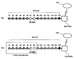
- the sensor nodes positioned below the sensor nodes N7 and N8 that are in the incapable communication state The data of N1 to N6 cannot be transmitted to the sink node N15, which causes a problem of loss.
- An object of the present invention for solving the above-mentioned problems is to provide a wireless sensor network that can minimize the problem that more sensing data is lost during transmission than the buffer capacity of each sensor node.
- Another object of the present invention is to wirelessly minimize the problem that the sensing data of sensor nodes located below are lost by the failed sensor node, even if some nodes of the sensor nodes constituting the wireless sensor network fail. It is to provide a sensor network.
- a first aspect of the present invention for solving the above problems relates to a wireless sensor network, the wireless sensor network, a plurality of linearly connected sensor nodes; A sink node connected to a top node of the sensor nodes; A control server for transmitting and receiving data with the sensor node and the sink node and controlling an operation; A gateway connected between the sink node and the control server to transmit and receive data; And a plurality of relay gateways connected to the control server, wherein the plurality of sensor nodes are divided into a predetermined number of subgroups, and sensor nodes positioned at the top of each of the divided subgroups are set as relay nodes. Each relay node is connected to the relay gateways, respectively.
- the relay node transmits the stored data to the control server through the connected relay gateway when the amount of data stored in its buffer exceeds a predetermined threshold. It is desirable to. In particular, the relay node determines whether the amount of data stored in the buffer reaches the threshold value, and if it is determined that the threshold value is reached, determines whether some of the data stored in the buffer should be transmitted to the sink node. If it is determined that the data should be transmitted to the sink node, it is more preferable to transmit the data in the sync node direction.
- a wireless sensor network includes: a plurality of linearly connected sensor nodes; A sink node connected to a top node of the sensor nodes; Control server; A gateway connected between the sink node and the control server to transmit and receive data; And a plurality of relay gateways connected to the control server, wherein the plurality of sensor nodes are divided into a predetermined number of subgroups, and sensor nodes positioned at the top of each of the divided subgroups are relay nodes.
- the relay nodes are respectively connected to the relay gateways,
- a relay node of a lower subgroup located below the subgroup to which the error node belongs is changed to a relay sink node, and the relay sink node is connected to the relay node. Send and receive data with the control server through.
- the incapable communication state of the sensor node is preferably defined to occur when a network link failure occurs in the sensor node and recovery of the generated network link failure fails. Do.
- the relay sink node searches for a sensor node located at an upper level, and when a sensor node located higher than the search result is found, the relay sink node is changed back to a relay node to be found. It is preferable to restore a communication path with a sensor node located and to transmit data through the restored communication path.
- the wireless sensor network by using a relay node and a relay gateway, a problem in which more sensing data is lost during transmission than the buffer capacity of each sensor node can be minimized. It is possible to minimize the problem that the sensing data of the sensor nodes that are located below the sensor node is lost by some faulty sensor node.
- FIG. 1 is a configuration diagram illustrating a wireless sensor network according to a first embodiment of the present invention.
- FIG. 2 is a diagram for describing data stored in a buffer of some sensor nodes according to the first embodiment of the present invention.
- 3 is a control procedure for explaining the operation of the wireless sensor network according to the first embodiment of the present invention.
- FIG. 4 is a configuration diagram illustrating a wireless sensor network according to a second embodiment of the present invention.
- 5 is a control procedure for explaining the operation of the wireless sensor network according to a second embodiment of the present invention.
- FIG. 6 is a block diagram illustrating a wireless sensor network according to the related art.
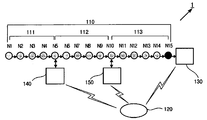
- the wireless sensor network 1 according to the first embodiment of the present invention shown in FIG. 1 transmits data sensed by each sensor node 110 constituting the network toward the sink node N15 positioned at the highest level. It has a linear structure and is connected by a distributed TDMA based MAC protocol.
- the wireless sensor network 1 according to the first embodiment of the present invention as shown in Figure 1, a plurality of sensor nodes 110, control server 120, gateway 130, relay nodes (N5, N10) ), And the first and second relay gateways (140, 150).
- the relay node is set to the sensor nodes disposed at the top of the subgroup among the plurality of sensor nodes, and each relay node is connected to the relay gateways, respectively.
- the data sensed from the plurality of sensor nodes 110 constituting the wireless sensor network 1 is increased to relay node (N5) If the data stored in N10) exceeds a predetermined threshold value (A in FIG. 2), the relay nodes N5 and N10 are changed to the relay sink nodes N5 and N10 that can serve as sink nodes. It is connected to the relay gateway (140, 150).
- the relay gateways 140 and 150 transmit the data stored in the relay sink nodes N5 and N10 to the control server 120, and the relay gateways 140 and 150 relay the command data transmitted from the control server 120. Transfer to node N5, N10.
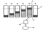
- FIG 2 illustrates data stored in buffers of the first node N1 to the sixth node N6.
- the sensor node 110 generates data through a sensing module (not shown) that senses a predetermined external environment, stores the data in its own buffer, and transmits the stored data to an upper sensor node.
- a sensing module not shown
- the control server 120 manages data transmitted through the plurality of sensor nodes 110 and the gateway 130 and controls the network.
- the gateway 130 connects the sink node N15 and the control server 120 to transfer data transmitted from the sink node N15 to the control server 120 and transmits command data transmitted from the control server 120. It delivers to the sink node N15.
- the relay nodes N5 and N10 are located at the top of each subgroup 111, 112, 113 when the plurality of sensor nodes 110 are divided into a predetermined number of subgroups 111, 112, and 113. Are set to the sensor nodes N5 and N10.
- the relay nodes N5 and N10 of each subgroup are connected to the relay gateways 140 and 150, respectively.
- the wireless sensor network 1 includes a first subgroup 111 and a sixth node including first to fifth nodes N1 to N5. And a third subgroup including the N6 to 10th nodes N10 and a third subgroup including the eleventh nodes N11 to 15th node N15.
- the fifth node N5 and the tenth node N10 correspond to the relay nodes N5 and N10
- the fifteenth node N15 corresponds to the sink node N15.
- the relay nodes N5 and N10 are changed to the relay sink nodes N5 and N10 that perform the function of the sink node.
- reference numeral N5 corresponds to a relay node
- a hatched portion B is data transmitted from lower sensor nodes N1 to N4
- a hatched portion C is a relay node.
- Data sensed at N5. Therefore, as shown in FIG. 2, when the data B and C stored in the relay node N5 exceed the threshold value A, the relay node N5 stores the data B stored in the relay gateway 140. , C).
- the threshold A is shown as approximately 2/3 of the buffer capacity, but the threshold A is preferably set to about 1/2 of the buffer capacity.
- the relay gateways 140 and 150 connect the relay nodes N5 and N10 and the control server 120 to each other to transmit data of the relay nodes N5 and N10 to the control server 120. After the data transmission is completed, the relay sink nodes N5 and N10 return to the relay nodes N5 and N10 which perform only the function of the sensor node 110 and normalize to the original network.
- the relay nodes N5 and N10 check the amount of data stored in their buffers, that is, data transmitted from lower nodes or sensed by the relay nodes (S310). That is, as shown in Figure 2, the relay node (N5) checks the amount of data (B, C) stored in its buffer.
- step S310 it is determined whether the amount of data stored in the buffer is greater than the threshold value (A) (S320). As shown in FIG. 2, it is determined whether the data B and C of the relay node N5 are larger than the threshold value A.
- FIG. 2 it is determined whether the data B and C of the relay node N5 are larger than the threshold value A.
- the stored data is transmitted toward the sink node N15 (S330). If the amount of data stored in the buffers of the relay nodes N5 and N10 in step S320 is greater than the threshold value A, the relay nodes N5 and N10 transmit to the sink node N15 among the data stored in the buffer. It is determined whether there is data that should be present (S340).
- step S330 if there is data to be transmitted to the sync node N15 among the data, step S330 is performed.
- the relay node N5 relays the data stored in the buffer (B and C of FIG. 2) to the relay gateways 140 and 150. To send).
- the relay gateways 140 and 150 connect the relay nodes N5 and N10 and the control server 120 to each other to transmit the data of the relay sink nodes N5 and N10 to the control server 120 (S360). .
- the first relay gateway 140 transmits data B and C of the relay sync node N5 to the control server 120.
- the wireless sensor network 1 uses the relay nodes N5 and N10 and the relay gateways 140 and 150 to sense data when the data of each sensor node increases. The problem of missing during transmission can be minimized.
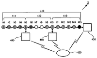
- the wireless sensor network 2 according to the second embodiment of the present invention shown in FIG. 4 has the same linear structure as the wireless sensor network (see FIG. 1) according to the above-described embodiment, and has a distributed TDMA based MAC protocol. Is connected by.
- the relay node N5 is changed into a relay sink node N5 and connected to the first relay gateway 440.
- the first relay gateway 440 transmits the data of the relay sink node N5 to the control server 420, and transfers the command data transmitted from the control server 420 to the relay sink node N5, thereby relaying the relay sink node ( A network of the first subgroup 411 by N5) can be configured.
- the wireless sensor network 2 includes a plurality of sensor nodes 410, a control server 420, a gateway 430, and relay nodes N5 and N10. ), And first and second relay gateways 440 and 450.
- each of the wireless sensor network 2 according to the second embodiment of the present invention will be described. Description of the same contents as in the above-described embodiment will be omitted.
- the relay nodes N5 and N10 are located at the top of each subgroup 411, 412, 413 when a plurality of sensor nodes 410 are divided into a predetermined number of subgroups 411, 412, 413. It is set as a sensor node.
- the wireless sensor network 2 of the present invention includes a first subgroup 411 including a first node N1 to a fifth node N5, and a sixth node N6 to a fifth node.
- the second subgroup 412 including the tenth node N10 and the third subgroup including the eleventh nodes N11 to the fifteenth node N15 may be divided into relay nodes N5 and N10.
- the fifth node N5 and the tenth node N10 correspond to the relay nodes N5 and N10
- the fifteenth node N15 corresponds to the sink node N15.
- the seventh node N7 and the eighth node N8 correspond to the error nodes N7 and N8, and the fifth node N5 corresponds to the relay sink node N5.
- the relay gateway 440 connects the relay sink node N5 and the control server 420 with each other to transfer the data of the relay sink node N5 to the control server 420. And transmits the command data transmitted from the control server 420 to the relay sync node N5.
- the sensor node where a network link failure occurs by the error nodes N7 and N8 is determined in advance.
- the link recovery algorithm is performed (S510). Referring to FIG. 4, when the seventh node N7 and the eighth node N8 correspond to the error nodes N7 and N8, the sixth node N6 and the ninth node N9 are network links. We will perform a recovery algorithm.
- step S520 it is determined whether the network link recovery is completed in step S510 (S520). As a result of the determination in step S520, when the restoration of the network link is completed, the process proceeds to step S590. This means that the original wireless sensor network 2 except the error nodes N7 and N8 is restored.
- step S520 when the restoration of the network link is not completed, the relay node N5 in the first subgroup 411 positioned below the second subgroup 412 to which the error nodes N7 and N8 belong. Is changed to the relay sink node N5 which performs the function of the sink node (S530).
- the first relay gateway 440 connects the changed relay sink node N5 and the control server 420 to each other to transmit data of the relay sink node N5 to the control server 420, and the control server 420.
- the command data transmitted from the host data is transferred to the relay sink node N5 to configure a network of the first subgroup 411 (S540).
- the relay sink node N5 determines whether to perform a procedure for searching for a sensor node located above to recover a communication inoperability state (S550).
- step S550 As a result of the determination of the step S550, when the procedure for searching for the sensor node located above is not performed, the process returns to the step S550. This means that the network of the first subgroup 411 configured in step S540 is maintained.
- step S550 when a procedure of searching for a sensor node located at a higher level is performed and an upper sensor node N9 located within a predetermined distance is found, the relay sink node N5 changed in step S530 to the relay node N5. Change again (S560).
- step S560 performs the same network link recovery algorithm as in step S510 (S570).
- step S580 when the restoration of the network link is completed, the wireless sensor network 2 to which the relay node N5 and the upper node N9 found in step S550 are connected to each other is restored. As a result, the network of the first subgroup 411 configured in step S540 is dismantled.
- step S580 when the restoration of the network link is not completed, the process returns to step S550. This means that the network of the first subgroup 411 configured in step S540 is maintained.
- the wireless sensor network 2 configures the network of the first subgroup 411 by using the relay node N5 and the first relay gateway 440, thereby providing an error node.
- N7 and N8 it is possible to minimize the problem that the sensing data of the sensor nodes N1 to N6 located below the data is lost.
- the wireless sensor network according to the present invention relates to efficient and secure transmission of sensed data, and can be widely used in the wireless sensor network field.
Landscapes
- Engineering & Computer Science (AREA)
- Computer Networks & Wireless Communication (AREA)
- Signal Processing (AREA)
- Mobile Radio Communication Systems (AREA)
Abstract
La présente invention concerne un réseau de capteurs radio. Le réseau de capteurs radio comprend plusieurs nœuds de capteurs connectés les uns aux autres de façon linéaire, un nœud synchronisé connecté à un nœud racine pris parmi les nœuds de capteurs, un serveur de commande, une passerelle montée entre le nœud synchronisé et le serveur de commande de façon à émettre et recevoir des données, et plusieurs passerelles relais. Quand les différents nœuds de capteurs sont répartis en un nombre prédéfini de sous-groupes, c'est le nœud de capteurs qui est en tête de chaque groupe et qui est connecté aux passerelles relais qui est défini comme nœud relais. Quand la quantité des données en mémoire dans le nœud de relais dépasse une limite maximale prédéfinie, les données ainsi conservées en mémoire sont transmises, via la passerelle relais, du nœud relais au serveur de commande. Ainsi, quand la quantité de données augmente dans l'un ou l'autre des nœuds de capteurs, l'invention permet de ramener à un minimum pendant la transmission la perte de données d'augmentation.
Priority Applications (1)
| Application Number | Priority Date | Filing Date | Title |
|---|---|---|---|
| US12/992,016 US20110069611A1 (en) | 2008-05-20 | 2009-05-08 | Wireless sensor network |
Applications Claiming Priority (2)
| Application Number | Priority Date | Filing Date | Title |
|---|---|---|---|
| KR1020080046432A KR100936130B1 (ko) | 2008-05-20 | 2008-05-20 | 무선 센서 네트워크 시스템 |
| KR10-2008-0046432 | 2008-05-20 |
Publications (2)
| Publication Number | Publication Date |
|---|---|
| WO2009142402A2 true WO2009142402A2 (fr) | 2009-11-26 |
| WO2009142402A3 WO2009142402A3 (fr) | 2010-02-11 |
Family
ID=41340656
Family Applications (1)
| Application Number | Title | Priority Date | Filing Date |
|---|---|---|---|
| PCT/KR2009/002415 WO2009142402A2 (fr) | 2008-05-20 | 2009-05-08 | Réseau de radiocommunications |
Country Status (3)
| Country | Link |
|---|---|
| US (1) | US20110069611A1 (fr) |
| KR (1) | KR100936130B1 (fr) |
| WO (1) | WO2009142402A2 (fr) |
Families Citing this family (12)
| Publication number | Priority date | Publication date | Assignee | Title |
|---|---|---|---|---|
| WO2011085149A2 (fr) | 2010-01-08 | 2011-07-14 | Interdigital Patent Holdings, Inc. | Procédé et appareil pour systèmes de communication de parcelle de données |
| KR101217773B1 (ko) * | 2010-12-07 | 2013-01-02 | 주식회사 에이에스엔 | 무선 센서 네트워크에서의 통신 방법 |
| US9065699B2 (en) | 2012-11-30 | 2015-06-23 | Cognosos, Inc. | Methods and systems for a distributed radio communications network |
| KR102020590B1 (ko) * | 2013-03-15 | 2019-09-16 | 주식회사 케이티 | M2m 디바이스 관리 방법 및 m2m 서비스 플랫폼 |
| KR101496585B1 (ko) | 2013-12-11 | 2015-02-25 | 경희대학교 산학협력단 | 무선 센서 네트워크에서 센서 노드의 버퍼 용량 설정 방법 |
| FR3026587A1 (fr) * | 2014-09-30 | 2016-04-01 | Orange | Technique d'acces par un dispositif maitre a une valeur prise par une caracteristique geree par un dispositif peripherique |
| US11810032B2 (en) | 2016-03-16 | 2023-11-07 | Triax Technologies, Inc. | Systems and methods for low-energy wireless applications using networked wearable sensors |
| US11170616B2 (en) | 2016-03-16 | 2021-11-09 | Triax Technologies, Inc. | System and interfaces for managing workplace events |
| US10692024B2 (en) * | 2016-03-16 | 2020-06-23 | Triax Technologies, Inc. | Wireless mesh network system for monitoring worksite events including detecting false events |
| US10769562B2 (en) | 2016-03-16 | 2020-09-08 | Triax Technologies, Inc. | Sensor based system and method for authorizing operation of worksite equipment using a locally stored access control list |
| CN107450344A (zh) * | 2017-09-21 | 2017-12-08 | 深圳市鑫汇达机械设计有限公司 | 一种基于无线传感器网络的智能家居系统 |
| CN113170374A (zh) * | 2018-12-24 | 2021-07-23 | 深圳市柔宇科技股份有限公司 | 组网方法及组网系统 |
Citations (2)
| Publication number | Priority date | Publication date | Assignee | Title |
|---|---|---|---|---|
| KR100656385B1 (ko) * | 2005-12-21 | 2006-12-11 | 전자부품연구원 | 선형 구조를 가지는 실시간 무선 센서 네트워크 통신방법 |
| KR100675365B1 (ko) * | 2004-12-29 | 2007-01-29 | 삼성전자주식회사 | 무선 센서 네트워크 환경에서 신뢰성을 보장하는 데이터전송 방법 |
Family Cites Families (7)
| Publication number | Priority date | Publication date | Assignee | Title |
|---|---|---|---|---|
| US7904569B1 (en) * | 1999-10-06 | 2011-03-08 | Gelvin David C | Method for remote access of vehicle components |
| KR100677754B1 (ko) * | 2005-03-11 | 2007-02-02 | 삼성전자주식회사 | 무선 센서 네트워크에서의 아이디 생성방법 및 등록방법 |
| KR100717962B1 (ko) * | 2005-07-15 | 2007-05-14 | 전자부품연구원 | 다수의 노드를 포함하는 무선 네트워크 시스템에서의데이터 전송 제어 방법 및 이를 이용한 센서 네트워크시스템 및 기록 매체 |
| JP2007312056A (ja) * | 2006-05-18 | 2007-11-29 | Oki Electric Ind Co Ltd | 無線通信システム、ネットワーク中継装置、及び通信方法 |
| JP4839152B2 (ja) * | 2006-08-04 | 2011-12-21 | 株式会社日立製作所 | センサネットワークシステム及びセンサネットワークのデータ処理方法 |
| US20080136606A1 (en) * | 2006-12-06 | 2008-06-12 | Electronics And Telecommunications Research Institute | Separable device for controlling node and sensor network node |
| US7836360B2 (en) * | 2007-04-09 | 2010-11-16 | International Business Machines Corporation | System and method for intrusion prevention high availability fail over |
-
2008
- 2008-05-20 KR KR1020080046432A patent/KR100936130B1/ko active IP Right Grant
-
2009
- 2009-05-08 US US12/992,016 patent/US20110069611A1/en not_active Abandoned
- 2009-05-08 WO PCT/KR2009/002415 patent/WO2009142402A2/fr active Application Filing
Patent Citations (2)
| Publication number | Priority date | Publication date | Assignee | Title |
|---|---|---|---|---|
| KR100675365B1 (ko) * | 2004-12-29 | 2007-01-29 | 삼성전자주식회사 | 무선 센서 네트워크 환경에서 신뢰성을 보장하는 데이터전송 방법 |
| KR100656385B1 (ko) * | 2005-12-21 | 2006-12-11 | 전자부품연구원 | 선형 구조를 가지는 실시간 무선 센서 네트워크 통신방법 |
Non-Patent Citations (1)
| Title |
|---|
| TAE-YUN CHUNG ET AL.: 'Implementation of a Remote Fire Monitoring System Based on Bidirectional USN' JOURNAL OF IEMEK vol. 2, no. 2, June 2007, pages 1 - 8 * |
Also Published As
| Publication number | Publication date |
|---|---|
| KR100936130B1 (ko) | 2010-01-12 |
| WO2009142402A3 (fr) | 2010-02-11 |
| US20110069611A1 (en) | 2011-03-24 |
| KR20090120558A (ko) | 2009-11-25 |
Similar Documents
| Publication | Publication Date | Title |
|---|---|---|
| WO2009142402A2 (fr) | Réseau de radiocommunications | |
| JP4835422B2 (ja) | ネットワーク装置及び通信システム | |
| US6603744B2 (en) | Connection establishment method, communication method, state change transmission method, state changing method, wireless apparatus, wireless device, and computer | |
| US7668994B2 (en) | Method for optimizing bandwidth utilization in bus systems | |
| US7054264B2 (en) | Interconnect and gateway protection in bidirectional ring networks | |
| US9077558B2 (en) | Client/bridge failure recovery method and system | |
| CN101392656A (zh) | 一种液压支架电液控制系统及其自组网方法 | |
| US20130301404A1 (en) | Communication system, communication method, and communication apparatus | |
| WO2011130965A1 (fr) | Réseau de capteurs sans fil, terminal mobile et procédé et système d'interconnexion s'y rapportant | |
| JP2008533881A (ja) | Rprリングネットワークのオン・オフリングの処理、データ転送方法及びそのネットワーク設備 | |
| US20030021281A1 (en) | Media converter and transmission system using the same | |
| JP4637021B2 (ja) | 伝送装置、伝送路リング間接続方法および伝送路リング間接続プログラム | |
| JPH0126211B2 (fr) | ||
| KR20100034395A (ko) | 산업용 제어네트워크 적용을 위한 무선 센서네트워크 및 그구성방법 | |
| JP5441566B2 (ja) | 通信端末、通信システムおよびノード切り替え方法 | |
| CN101222405B (zh) | 可用于快速恢复环网冗余的模块及其使用方法 | |
| KR100713416B1 (ko) | 복수의 프로토콜을 지원하는 리피터 장치 및 그장치에서의 프로토콜 변환을 위한 제어 방법 | |
| Cisco | Configuring IBM Network Media Translation | |
| Cisco | Configuring IBM Network Media Translation | |
| Cisco | Configuring IBM Network Media Translation | |
| Cisco | Configuring IBM Network Media Translation | |
| Cisco | Configuring IBM Network Media Translation | |
| Cisco | Configuring IBM Network Media Translation | |
| Cisco | Configuring IBM Network Media Translation | |
| KR100396843B1 (ko) | 이더넷 스위칭 장치를 이용한 아이피씨 메시지 교환장치및 방법 |
Legal Events
| Date | Code | Title | Description |
|---|---|---|---|
| 121 | Ep: the epo has been informed by wipo that ep was designated in this application |
Ref document number: 09750724 Country of ref document: EP Kind code of ref document: A2 |
|
| WWE | Wipo information: entry into national phase |
Ref document number: 12992016 Country of ref document: US |
|
| NENP | Non-entry into the national phase |
Ref country code: DE |
|
| 122 | Ep: pct application non-entry in european phase |
Ref document number: 09750724 Country of ref document: EP Kind code of ref document: A2 |