WO2009142226A1 - 照明装置および表示装置 - Google Patents
照明装置および表示装置 Download PDFInfo
- Publication number
- WO2009142226A1 WO2009142226A1 PCT/JP2009/059247 JP2009059247W WO2009142226A1 WO 2009142226 A1 WO2009142226 A1 WO 2009142226A1 JP 2009059247 W JP2009059247 W JP 2009059247W WO 2009142226 A1 WO2009142226 A1 WO 2009142226A1
- Authority
- WO
- WIPO (PCT)
- Prior art keywords
- region
- lighting device
- light
- linear light
- dimensional structure
- Prior art date
Links
Images


Classifications
-
- G—PHYSICS
- G02—OPTICS
- G02F—OPTICAL DEVICES OR ARRANGEMENTS FOR THE CONTROL OF LIGHT BY MODIFICATION OF THE OPTICAL PROPERTIES OF THE MEDIA OF THE ELEMENTS INVOLVED THEREIN; NON-LINEAR OPTICS; FREQUENCY-CHANGING OF LIGHT; OPTICAL LOGIC ELEMENTS; OPTICAL ANALOGUE/DIGITAL CONVERTERS
- G02F1/00—Devices or arrangements for the control of the intensity, colour, phase, polarisation or direction of light arriving from an independent light source, e.g. switching, gating or modulating; Non-linear optics
- G02F1/01—Devices or arrangements for the control of the intensity, colour, phase, polarisation or direction of light arriving from an independent light source, e.g. switching, gating or modulating; Non-linear optics for the control of the intensity, phase, polarisation or colour
- G02F1/13—Devices or arrangements for the control of the intensity, colour, phase, polarisation or direction of light arriving from an independent light source, e.g. switching, gating or modulating; Non-linear optics for the control of the intensity, phase, polarisation or colour based on liquid crystals, e.g. single liquid crystal display cells
- G02F1/133—Constructional arrangements; Operation of liquid crystal cells; Circuit arrangements
- G02F1/1333—Constructional arrangements; Manufacturing methods
- G02F1/1335—Structural association of cells with optical devices, e.g. polarisers or reflectors
- G02F1/1336—Illuminating devices
- G02F1/133602—Direct backlight
- G02F1/133606—Direct backlight including a specially adapted diffusing, scattering or light controlling members
-
- G—PHYSICS
- G02—OPTICS
- G02B—OPTICAL ELEMENTS, SYSTEMS OR APPARATUS
- G02B3/00—Simple or compound lenses
- G02B3/0006—Arrays
- G02B3/0037—Arrays characterized by the distribution or form of lenses
- G02B3/0043—Inhomogeneous or irregular arrays, e.g. varying shape, size, height
-
- G—PHYSICS
- G02—OPTICS
- G02B—OPTICAL ELEMENTS, SYSTEMS OR APPARATUS
- G02B5/00—Optical elements other than lenses
- G02B5/02—Diffusing elements; Afocal elements
- G02B5/0205—Diffusing elements; Afocal elements characterised by the diffusing properties
- G02B5/0263—Diffusing elements; Afocal elements characterised by the diffusing properties with positional variation of the diffusing properties, e.g. gradient or patterned diffuser
-
- G—PHYSICS
- G02—OPTICS
- G02F—OPTICAL DEVICES OR ARRANGEMENTS FOR THE CONTROL OF LIGHT BY MODIFICATION OF THE OPTICAL PROPERTIES OF THE MEDIA OF THE ELEMENTS INVOLVED THEREIN; NON-LINEAR OPTICS; FREQUENCY-CHANGING OF LIGHT; OPTICAL LOGIC ELEMENTS; OPTICAL ANALOGUE/DIGITAL CONVERTERS
- G02F1/00—Devices or arrangements for the control of the intensity, colour, phase, polarisation or direction of light arriving from an independent light source, e.g. switching, gating or modulating; Non-linear optics
- G02F1/01—Devices or arrangements for the control of the intensity, colour, phase, polarisation or direction of light arriving from an independent light source, e.g. switching, gating or modulating; Non-linear optics for the control of the intensity, phase, polarisation or colour
- G02F1/13—Devices or arrangements for the control of the intensity, colour, phase, polarisation or direction of light arriving from an independent light source, e.g. switching, gating or modulating; Non-linear optics for the control of the intensity, phase, polarisation or colour based on liquid crystals, e.g. single liquid crystal display cells
- G02F1/133—Constructional arrangements; Operation of liquid crystal cells; Circuit arrangements
- G02F1/1333—Constructional arrangements; Manufacturing methods
- G02F1/1335—Structural association of cells with optical devices, e.g. polarisers or reflectors
- G02F1/1336—Illuminating devices
- G02F1/133602—Direct backlight
- G02F1/133611—Direct backlight including means for improving the brightness uniformity
-
- G—PHYSICS
- G02—OPTICS
- G02F—OPTICAL DEVICES OR ARRANGEMENTS FOR THE CONTROL OF LIGHT BY MODIFICATION OF THE OPTICAL PROPERTIES OF THE MEDIA OF THE ELEMENTS INVOLVED THEREIN; NON-LINEAR OPTICS; FREQUENCY-CHANGING OF LIGHT; OPTICAL LOGIC ELEMENTS; OPTICAL ANALOGUE/DIGITAL CONVERTERS
- G02F1/00—Devices or arrangements for the control of the intensity, colour, phase, polarisation or direction of light arriving from an independent light source, e.g. switching, gating or modulating; Non-linear optics
- G02F1/01—Devices or arrangements for the control of the intensity, colour, phase, polarisation or direction of light arriving from an independent light source, e.g. switching, gating or modulating; Non-linear optics for the control of the intensity, phase, polarisation or colour
- G02F1/13—Devices or arrangements for the control of the intensity, colour, phase, polarisation or direction of light arriving from an independent light source, e.g. switching, gating or modulating; Non-linear optics for the control of the intensity, phase, polarisation or colour based on liquid crystals, e.g. single liquid crystal display cells
- G02F1/133—Constructional arrangements; Operation of liquid crystal cells; Circuit arrangements
- G02F1/1333—Constructional arrangements; Manufacturing methods
- G02F1/1335—Structural association of cells with optical devices, e.g. polarisers or reflectors
- G02F1/1336—Illuminating devices
- G02F1/133602—Direct backlight
- G02F1/133606—Direct backlight including a specially adapted diffusing, scattering or light controlling members
- G02F1/133607—Direct backlight including a specially adapted diffusing, scattering or light controlling members the light controlling member including light directing or refracting elements, e.g. prisms or lenses
Definitions
- the present invention relates to an illumination device that illuminates, for example, a transmissive liquid crystal panel from behind and a display device including the illumination device.
- a liquid crystal display device in which a backlight (illumination device) is arranged behind a liquid crystal panel is used as a display device for a word processor, a laptop personal computer, or the like.
- a linear light source such as a fluorescent tube is disposed on a side end portion of the light guide plate, and a liquid crystal panel is mounted on the light guide plate in order to reduce the weight and thickness.
- the installed edge light type lighting device was the mainstream.
- Patent Document 1 A direct-type illumination device in which the above-mentioned is disposed is used.
- the illumination device becomes larger and thinner, the number of linear light sources used in the illumination device increases, and a flat optical element disposed immediately above the linear light source And the gap with the linear light source tends to be narrowed.
- the number of linear light sources increases, the power consumption of the lighting device increases and the power consumption of the television also increases. Therefore, the number of linear light sources is not increased as much as possible, that is, adjacent linear light sources. It is conceivable to suppress an increase in power consumption by widening the interval between them.
- the in-plane brightness of the irradiation light beam of the lighting device is increased at a position immediately above the linear light sources, and is decreased at a position immediately above the central portion between the linear light sources, resulting in uneven brightness in the plane. There was a problem that it occurred. Further, when the gap between the flat optical element disposed immediately above the linear light source and the linear light source is narrowed, there is a problem that uneven luminance occurs in the same manner.
- the present invention has been made in view of such problems, and an object thereof is to provide an illumination device and a display device capable of reducing in-plane luminance unevenness when viewed from an oblique direction as well as a front direction. There is to do.
- the illumination device of the present invention includes a plurality of linear light sources arranged so that the central axes thereof are parallel to each other and included in one plane, a reflecting plate arranged to face each linear light source, A flat diffusing member disposed on the opposite side of the reflecting plate with respect to the surface, and an optical member disposed between each linear light source and the diffusing member.
- the optical member has a light incident surface parallel to the one surface and a light exit surface.
- the light emitting surface is provided with a first three-dimensional structure in a first region facing each linear light source in the normal direction of the one surface, and the one linear light source and the one linear light source
- a second three-dimensional structure is provided in an intermediate region between other adjacent linear light sources and a second region facing the normal direction of the one surface.
- the first portion in which the light incident perpendicularly to the light incident surface from each linear light source is totally reflected by the first three-dimensional structure and generates return light toward the reflecting plate is the normal line of the one surface.
- the proportion of the first region when viewed from the direction is K1
- the light incident perpendicularly to the light incident surface from each linear light source is totally reflected by the second three-dimensional structure and generates return light that travels toward the reflector.
- the display device of the present invention includes a panel driven based on an image signal and the illumination device that illuminates the panel.
- K1 is larger than K2 in the optical member. That is, since the first region directly above each linear light source is less likely to transmit light than the second region sandwiched between the first regions, the return light from the first region is reflected by the reflection sheet. After being circulated in the lighting device, for example, by being reflected by the light, etc., most of the circulating light passes through the second region where light can be relatively easily transmitted. Accordingly, when the light amount distribution of the light incident on the optical member is compared with the light amount distribution of the light that has passed through the optical member, the light amount is moved from the first region to the second region.
- the second region is easier to transmit light than the first region, it can be said that the second region has a low light condensing property and a high diffusibility. As a result, the amount of light passing through the second region is widely distributed not only in the front but also in the oblique direction.
- K1 is set to be larger than K2, so that the amount of light is moved from the first region to the second region, and the second member
- the amount of light passing through the region can be widely distributed not only in the front but also in the oblique direction. Thereby, not only the front direction but also in-plane luminance unevenness when viewed from an oblique direction can be reduced.
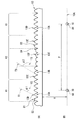
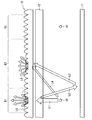
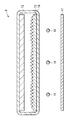
- FIG. 1 shows a cross-sectional configuration of a lighting device 1 according to an embodiment of the present invention.
- the illuminating device 1 includes a plurality of linear light sources 10, a reflecting plate 11, a diffusing plate 12, an optical sheet 13 (optical member), and a diffusing sheet 14 (diffusing member).
- the reflecting plate 11 is disposed behind each linear light source 10 so as to face each linear light source 10, and the diffusing plate 12, the optical sheet 13, and the diffusing sheet 14 are on the opposite side of the reflecting plate 11 with respect to each linear light source 10.
- the linear light sources 10 are arranged in this order from the side of the linear light sources 10 and are opposed to the linear light sources 10.
- the plurality of linear light sources 10 include, for example, a hot cathode tube (HCFL), a cold cathode tube (CCFL), or a plurality of point light sources (LEDs, etc.) arranged linearly.
- the central axes AX are arranged so as to be parallel or substantially parallel to each other and included in one surface (10A).
- the several linear light source 10 may be arrange
- the reflection plate 11 is disposed opposite to the surface 10A including the central axis AX of each linear light source 10 at a position separated by a predetermined gap, and has a reflective surface on the linear light source 10 side.
- the reflecting surface preferably has not only regular reflection but also diffuse reflection. In order to exhibit such functions of regular reflection and diffuse reflection, it is possible to use a resin colored white for the reflection surface. In that case, it is preferable to obtain high light reflection characteristics. Examples of such a material include polycarbonate resin and polybutylene terephthalate resin.
- the diffusion plate 12 is, for example, a thick and highly rigid optical sheet having a light diffusion layer formed by dispersing a diffusion material (filler) inside a relatively thick plate-like transparent resin.
- the diffusion plate 12 also functions as a support for supporting other optical sheets (for example, the optical sheet 13 and the diffusion sheet 14).
- the diffusion plate 12 is formed by dispersing a diffusion material (filler) inside a relatively thick plate-like transparent resin, and a transparent material containing a diffusion material on a relatively thin film-like transparent resin. It may be a combination of a resin (binder) applied and formed.
- the plate-like or film-like transparent resin for example, a light-transmitting thermoplastic resin such as PET, acrylic and polycarbonate is used.
- the light diffusion layer included in the diffusion plate 12 has a thickness of 1 mm or more and 5 mm or less, for example.
- the light diffusing material is made of particles having an average particle diameter of, for example, 0.5 ⁇ m or more and 10 ⁇ m or less, and in the transparent resin in the range of 0.1 parts by weight or more and 10 parts by weight or less with respect to the total weight of the light diffusing layer. Are distributed.
- the light diffusing material include organic fillers and inorganic fillers, but hollow particles may be used as the light diffusing material.
- this diffusion plate 12 has a function of diffusing light from each linear light source 10 and return light from the optical sheet 13 side.
- the light diffusing layer is thinner than 1 mm, the light diffusing property is impaired, and the sheet rigidity may not be secured when the diffusing plate 12 is supported by a casing (not shown). If the light diffusion layer is thicker than 5 mm, it is difficult to dissipate the heat when the diffusion plate 12 is heated by light from the light source, and the diffusion plate 12 may be bent.
- the average particle diameter of the light diffusing material is in the range of 0.5 to 10 ⁇ m, and the light diffusing material is dispersed in the transparent resin in the range of 0.1 to 10 parts by weight with respect to the total weight of the light diffusing layer. If it is, the effect as a light diffusing material is efficiently developed, and uneven brightness can be efficiently eliminated by combination with the optical sheet 13 described later.
- the diffusion sheet 14 is, for example, a thin optical sheet formed by applying a transparent resin containing a light diffusing material on a relatively thin film-like transparent resin.
- the diffusion sheet 14 has a function of diffusing light that has passed through the diffusion plate 12 and the optical sheet 13.
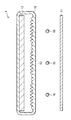
- the optical sheet 13 is a thin optical sheet in which a plurality of convex portions 13A, 13B, and 13C are arranged on the surface on the diffusion sheet 14 side (light emission side).
- 2A is an enlarged view of the optical sheet 13 shown in FIG. 1
- FIG. 2B shows the positions of the convex portions 13A, 13B, and 13C of the optical sheet 13 shown in FIG. The positional relationship with the linear light source 10 is shown.
- the convex portion 13A corresponds to a specific example of the “first convex portion” of the present invention
- the convex portions 13B and 13C correspond to a specific example of the “second convex portion” of the present invention.
- the optical sheet 13 may be bonded on the surface of the diffusion plate 12 with an adhesive or the like.
- the optical sheet 13 may be integrally formed using, for example, a translucent resin material, for example, one or a plurality of types of thermoplastic resins, or a translucent substrate, for example, An energy ray (for example, ultraviolet ray) curable resin may be transferred onto PET (polyethylene terephthalate).
- a translucent resin material for example, one or a plurality of types of thermoplastic resins, or a translucent substrate, for example,
- An energy ray (for example, ultraviolet ray) curable resin may be transferred onto PET (polyethylene terephthalate).
- thermoplastic resin having a refractive index of 1.4 or more in consideration of the function of controlling the light emission direction.
- resins include polycarbonate resins, acrylic resins such as PMMA (polymethyl methacrylate resin), polyolefin resins such as polyethylene (PE) and polypropylene (PP), polyester resins such as polyethylene terephthalate, and MS (methyl methacrylate).
- the plurality of convex portions 13A, 13B, and 13C have a three-dimensional shape that is linear, conical, or waffle that extends along a plane parallel to the surface 10A of the linear light source 10.
- each convex part 13A, 13B, 13C has a linear solid shape
- the extending direction of each convex part 13A, 13B, 13C is mutually parallel to the extending direction of the linear light source 10.
- the linear light sources 10 may be arranged so as to intersect within the allowable range in terms of optical characteristics.
- a plurality of point light sources are arranged in a grid
- two optical sheets 13 are arranged in a stacked manner, or a plurality of convex portions 13A, 13B, 13C are conical or waffle. It is preferable to use a three-dimensional shape.
- the plurality of convex portions 13A are arranged in the first region R1 facing each linear light source 10 in the normal direction of the surface 10A.
- Each convex portion 13A has a three-dimensional structure (first three-dimensional structure) that expresses optical characteristics that are difficult to transmit incident light from the linear light source 10 side as a whole in the first region R1.
- the plurality of convex portions 13B and 13C are opposed to the intermediate region between the one linear light source 10 and another linear light source 10 adjacent to the one linear light source 10 in the normal direction of the surface 10A. 2 is disposed in the region R2.
- Each of the convex portions 13B and 13C has a three-dimensional structure (second three-dimensional structure) that expresses optical characteristics that allow relatively easy passage of incident light from the linear light source 10 side as the entire second region R2. Further, in the second region R2, the convex portion 13B is disposed relatively closer to the linear light source 10, and the convex portion 13C is relatively separated from the linear light source 10, that is, the linear light sources adjacent to each other. It is arranged in the middle of 10 and in the vicinity thereof.
- the reason why the first three-dimensional structure is less likely to transmit incident light from the linear light source 10 side than the second three-dimensional structure is that A1 and A2 (described later) satisfy the following expression (1). Is almost equivalent to
- ⁇ 1 is an angle formed between the contact surface T1 in contact with the convex portion 13A and the surface T2 parallel to the surface 10A.
- ⁇ 2 is an angle formed by a contact surface T3 that is in contact with the convex portion 13B or the convex portion 13C and a surface T2 that is parallel to the surface 10A.
- A1 is the ratio of the portion where ⁇ 1 satisfies formula (2) to the first region R1 when the optical sheet 13 is viewed from the normal direction of the surface 10A.
- A2 is the ratio of the portion where ⁇ 2 satisfies the formula (3) to the second region R2 when the optical sheet 13 is viewed from the normal direction of the surface 10A.
- the ratio of transmitting through the optical sheet 13 is more dominant than the ratio of being reflected by the optical sheet 13 and returning light.
- the first region R1 (convex portion 13A) has higher front luminance and lower oblique luminance than the second region R2 (convex portions 13B and 13C). It can be said that the light condensing property is stronger than that of the second region R2, and the light condensing property is weaker than that of the first region R1 in the second region R2.
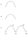
- the convex portion 13A has a convex aspherical curved surface S1 at the apex portion 13D and the vicinity thereof, and an inclined plane S2 that smoothly continues to the curved surface S1 at other portions.
- the angle of the tangent surface of the inclined plane S2 (inclination angle of the inclined plane S2) satisfies the above equation (2), and the angle of the tangent surface of the curved surface S1 is At least in the vicinity of the top portion 13D and the top portion 13D, it is small enough not to satisfy the above formula (2).
- the convex portion 13B has a convex aspherical curved surface S3 as a whole
- the convex portion 13C has a convex aspherical curved surface S4 as a whole.
- the angle of the tangent surfaces of the curved surfaces S3 and S4 satisfies the above-mentioned formula (3) and is gentler (smaller) than the angle of the tangent surface of the inclined plane S2 of the convex portion 13A, and
- the tangent surface angle of the curved surface S4 is gentler (smaller) than the tangential surface angle of the curved surface S3.
- convex portions 13A, 13B, and 13C are not limited to the shapes exemplified above, and can be deformed within a range that satisfies the above formulas (1) to (3).
- the convex portion 13A may have an aspherical convex shape as shown in the convex portions 13B and 13C of FIG. 2, or a triangular prism shape (prism shape) with no roundness at the top, or FIG.
- a flat surface 13H may be provided between the convex portions 13A adjacent to each other.
- the convex portions 13B and 13C have a triangular prism shape having a convex aspherical curved surface at the apex portions 13E and 13F and the vicinity thereof, and an inclined plane smoothly continuing to the curved surface at other portions.
- a polygonal prism shape constituted by a large number of inclined planes as shown in FIG. 3 (A), a spherical shape as shown in FIG. 3 (B), and a flat surface 13G as shown in FIG. 3 (C). It may be a shape to include.
- the curvature of the curved surface of the convex portion 13A is smaller than the curvature of the curved surface of the convex portion 13B or 13C.
- the inclination angle of the inclined plane of the convex portion 13A is the inclined plane of the convex portion 13B or 13C. It is preferable that it is larger than the inclination angle.
- the height of the convex portion 13A may be higher than the height of the convex portion 13B or 13C.
- region R1 is the optical sheet 13 from the normal line direction of the surface 10A.
- the proportion of the first region R1 when viewed is K3, and the flat surface of the second region R2 is the proportion of the second region R2 when the optical sheet 13 is viewed from the normal direction of the surface 10A.
- the expressions (2) and (3) are preferably applied when a material having a refractive index of about 1.5 to 1.6, which is generally used for optical members, is used for the optical sheet 13. Therefore, when an uncommon material is used for the optical sheet 13, the upper limit and lower limit values of the above formulas (2) and (3) are slightly shifted, so the upper and lower limit values are finely adjusted according to the material. It is necessary to do.
- the above formulas (1) to (3) are applicable to various profiles that light generally incident on the light incident surface of the optical sheet 13 has. Therefore, when the light incident on the light incident surface of the optical sheet 13 has a profile in which the luminance of the component incident perpendicularly to the light incident surface is higher than the luminance of the component incident obliquely on the light incident surface, Even when the luminance of the component incident perpendicularly to the incident surface has a profile almost equal to the luminance of the component incident obliquely to the light incident surface (typically when it is Lambertian light), the above formula is used. (1) to (3) hold.
- the portion where ⁇ 2 satisfies the expression (3) causes the optical sheet 13 to be separated from the normal direction of the surface 10A.
- the ratio of each of the plurality of divided sections gradually or intermittently increases as the distance from the linear light source 10 increases.
- the portion where ⁇ 1 satisfies the formula (2) is the optical sheet 13 from the normal direction of the surface 10A.
- the ratio of each of the plurality of divided sections gradually or intermittently increases as the distance from the linear light source 10 increases.
- the convex portions 13A, 13B, and 13C are configured so that all the light incident perpendicularly to the light incident surface of the optical sheet 13 from each linear light source 10 is entirely on the surface of the convex portion 13A.
- the ratio of the return light generation portion r1 (first portion) that is reflected and generates return light toward the reflection plate 11 to the first region R1 when the optical sheet 13 is viewed from the normal direction of the surface 10A is K1.
- the return light generating portion r2 (second light) in which light perpendicularly incident on the light incident surface of the optical sheet 13 from each linear light source 10 is totally reflected on the surfaces of the convex portions 13B and 13C and generates return light toward the reflecting plate 11.
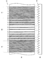
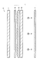
- FIG. 4A schematically shows an example of the distribution of the return light generation portions r1 and r2 when the optical sheet 13 is viewed from the upper surface
- FIG. 4B is a side view of the optical sheet 13.
- FIG. It is a figure and shows the relationship between distribution of return light generation
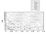
- FIG. 5 shows the relationship between the unevenness ratio obtained by the following equation (11) and P / H.
- P is the distance between the central axis AX of one linear light source 10 and the central axis AX of another linear light source 10 adjacent to the one linear light source 10 (see FIG. 2).
- H is the distance between the surface of the optical sheet 13 on the linear light source 10 side (surface 10A side) and the surface 10A (see FIG. 2).
- the unevenness ratio in FIG. 5 is obtained by actually measuring the light emitted from the diffusion sheet 14.
- the broken line in FIG. 5 is drawn at a 3% unevenness rate.
- the non-uniformity rate of 3% is an upper limit that a person cannot visually recognize the display non-uniformity (or is not concerned about the display non-uniformity), and is one of guidelines for display quality.
- Unevenness rate (%) ((maximum luminance ⁇ minimum luminance) / average luminance) ⁇ 100 (11)
- FIG. 5 shows that when K1 and K2 satisfy Expression (6), P / H can be increased up to 3.4.
- P / H is up to 4.0.
- P / H is up to 4.7.
- Equation (9) P / H should be increased to 5.3 at maximum, and when K1 and K2 satisfy Equation (10), P / H should be increased to 5.9 at maximum. Can do.
- the light emitted from each linear light source 10 enters the diffuser 12 directly or after being reflected by the reflector 11 or the like, and is diffused by the diffuser 12.
- the diffused light is incident on the back surface of the optical sheet 13 and is condensed or diffused according to the shape of the convex portions 13A, 13B, and 13C formed on the upper surface, and then diffused and diffused by the diffusion sheet 14.
- An object to be irradiated (not shown) disposed on the sheet 14 is illuminated.
- a prism sheet raises light in a specific direction in the front direction (perpendicular to the incident surface) with respect to incident light from various directions, and totally reflects light incident at an angle close to the incident surface. It works to return to the light source side. Since the base angle of each prism of the prism sheet acting in this way is usually 40 degrees or more and 58 degrees or less, an optical sheet having an inclination angle within such a range is the same as the prism sheet described above. Similarly, it not only has a strong light collecting action, but also has an action of returning a large amount of light, that is, an action of making it difficult for light to pass through. Therefore, the three-dimensional structure having a strong light collecting action is also a three-dimensional structure that generates return light.
- a three-dimensional structure with a weak condensing action is a three-dimensional structure that is easy to transmit light and hardly generate return light.
- the return light that is reflected by the three-dimensional structure having a relatively strong light collecting action and is directed to the reflection plate is reflected by the reflection plate, etc. Most of them pass through a portion that is relatively easy to transmit light, that is, a three-dimensional structure having a relatively weak light collecting effect (or a strong diffusivity).
- the first region R1 directly above each linear light source 10 is less likely to transmit light than the second region R2 sandwiched between the first regions R1 (that is, (Equations (1) to (3) and Equation (5) are satisfied), as shown in FIG. 6, the incident light L1 incident on the first region R1 is reflected by the first region R1. After the return light L2 from the first region R1 toward the reflector 11 is reflected by the reflector 11 or the like and circulates in the lighting device 1, most of the circulated light L3 relatively transmits light. It passes through the easy second region R2. Further, much of the incident light L4 that is directly incident on the second region R2 from the linear light source 10 also passes through the second region R2. As a result, when the light amount distribution of the light incident on the optical sheet 13 and the light amount distribution of the light that has passed through the optical sheet 13 are compared, the light amount moves from the first region R1 to the second region R2. .
- the second region R2 since the second region R2 is easier to transmit light than the first region R1, the second region R2 has weak light condensing property (or no light condensing property) or diffusibility. Can be said to be strong.
- the amount of light L5 that has passed through the second region R2 is widely distributed not only in the front but also in the oblique direction. The amount of light in the oblique direction can also be increased.
- the light condensing property since the light condensing property is strong, the light amount of the light L6 that has passed through the first region R1 is distributed more directed in the front direction than the light L5.
- the first region R1 is located immediately above each of the linear light sources 10, an originally large portion of the light emitted from each of the linear light sources 10 is collected by the condensing action in the first region R1. Lighted. As a result, when the optical sheet 13 is viewed from the front direction, the portion corresponding to the first region R1 becomes brighter than when the optical sheet 13 is not provided.
- the diffusion sheet 14 since the diffusion sheet 14 is disposed immediately above the optical sheet 13, the light quantity in the front direction and the light quantity in the oblique direction are averaged by the diffusion sheet 14, and as a result, the front direction and the oblique direction are obtained. The luminance unevenness in both directions can be reduced.
- FIG. 6 schematically shows that the luminance in the front direction of the light L5 is smaller than the luminance in the front direction of the light L6, and the luminance in the oblique direction of the light L5 is larger than the luminance in the oblique direction of the light L6.
- the light L5 and L6 having such a profile is diffused by the diffusion sheet 14, so that the light emitted from the diffusion sheet 14 is diffused so that the luminance in the front direction and the luminance in the oblique direction are approximately equal. It becomes light (typically Lambertian light).
- Lambertian light typically Lambertian light
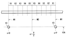
- the line passing through each central axis AX is the X axis
- the line orthogonal to the X axis is the Y axis
- the central axis AX of one linear light source 10 is the origin of the X axis. Is divided into five sections (X1 to X5) at equal intervals between the line M1 passing through the line M2 and the line M2 passing through the point P / 2 away from the origin (center between the linear light sources 10).
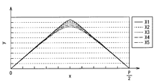
- a case where the shape of the convex portion of the included optical sheet 13 is the shape shown in FIG.
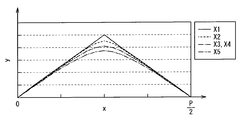
- the shape of the convex part of the optical sheet 13 contained in each section mentioned above is made into the shape shown in FIG. That is, the arrangement of the convex portions in Comparative Example 1 is opposite to the arrangement of the convex portions in Example 1 in the positional relationship with the linear light source 10.
- Example 1 a convex portion having a relatively strong condensing function is formed on the linear light source 10, and a convex portion having a relatively weak condensing function (or a strong diffusibility) is linear. It is formed between the light sources 10.
- convex portions having relatively weak condensing action or strong diffusibility are formed between the linear light sources 10, and convex portions having relatively strong condensing action are linear light sources 10. Formed on top. Note that, in P / 2 ⁇ x ⁇ P, convex portions obtained by inverting the shape in 0 ⁇ x ⁇ P / 2 are arranged, and each convex portion is periodically arranged corresponding to the linear light source 10.
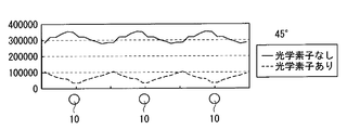
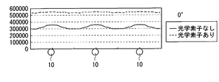
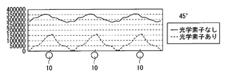
- FIGS. 10 shows the in-plane luminance distribution in the front direction when the optical sheet of Example 1 is used and when it is eliminated
- FIG. 11 shows the oblique distribution when the optical sheet of Example 1 is used and when it is eliminated
- FIG. 12 shows the in-plane luminance distribution when the optical sheet of Comparative Example 1 is used and when it is eliminated
- FIG. 13 shows when the optical sheet of Comparative Example 1 is used and when the optical sheet of Comparative Example 1 is eliminated.
- Each of the in-plane luminance distributions in the oblique direction is shown.
- the first region R1 and the second region R2 each have a flat surface
- the expression (4) when the expression (4) is satisfied, the first region R1 and the second region R2 Even if the shape and size of the convex portions formed in the second region R2 are the same, the formula (1) or the formula (5) is satisfied. Therefore, even in such a case, in-plane luminance unevenness can be reduced in both the front direction and the oblique direction.
- in-plane luminance unevenness occurs when P / H is increased.
- P / H increases.
- One is when the distance between the linear light source 10 and the diffusion plate 12 is reduced to reduce the thickness, and the other is when the number of linear light sources 10 is reduced. This is when the lights are reduced.
- the display device of the present embodiment is suitable for light saving among these two cases. In the present embodiment, if the position of K1 on the optical sheet 13 is shifted in the arrangement direction of the linear light sources 10 due to the relationship with the linear light sources 10, luminance unevenness may occur.
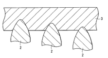
- a master for transfer in advance.
- the master can be created, for example, by cutting the surface of a metal roll with a blade having a shape to be transferred.
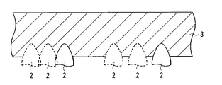
- a cutting tool 2 having a contact surface angle near the top of 40 degrees or less and a contact surface angle near the bottom of 40 degrees or more is prepared.
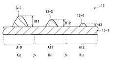
- FIG. 15 it is preferable to change the cutting depth of the blade 2 with respect to the master 3 in accordance with the place to cut.
- the convex portions 13-2 and 13-3 having a height and shape corresponding to the cutting depth are formed on the base material 13-1. , 13-4 can be formed, the ratio (K10, K11, K12) of the portion where the return light is generated in each region (A10, A11, A12) can be made different.
- the optical sheet 13 can be created simply by creating the master 3 using the single blade 2, it is possible to suppress an increase in manufacturing cost. In this case, since the height of the convex portion varies depending on the location, it is possible to prevent the optical sheet 13 from sticking to another optical element arranged on the convex portion side.
- a cutter 2 having a contact surface angle near the top of 40 degrees or less and a contact surface angle near the bottom of 40 degrees or more is prepared.
- the cutting width (pitch) for the master 3 may be changed.
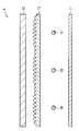
- the master 3 thus formed is used to form a plurality of convex portions 13-5 having a pitch corresponding to the cutting width on the base material 13-1, as shown in FIG.
- the ratio (K13, K14) occupied by the portion where the return light is generated can be made different.
- the optical sheet 13 can be created simply by creating the master 3 using the single blade 2, it is possible to suppress an increase in manufacturing cost.
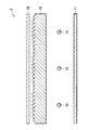
- the diffusing plate 12 is disposed between the optical sheet 13 and the linear light source 10, but the diffusing plate 12 is placed on the optical sheet 13 as shown in the illumination device 4 of FIG. You may arrange.
- the linear light source 10 is disposed immediately below the optical sheet 13, it is preferable to devise a technique for increasing the positioning accuracy of the optical sheet 13 with respect to the linear light source 10.
- a convex portion having the same characteristics as the convex portion of the optical sheet 13 is provided on the surface on the light emission side of the base material having the same function as the diffusion plate 12.
- the optical sheet 15 may be provided immediately above the linear light source 10, and the diffusion sheet 14 may be provided thereon.
- the optical sheet 15 may be formed in a lump using a method such as a melt extrusion method or an injection molding method.
- the optical sheet 15 includes a diffusing agent in the optical sheet 13 on the surface of the diffusion plate 12. It may be formed by pasting together.
- various optical elements for example, the diffusion plate 12, the optical sheet 13, the diffusion sheet 14, and the optical sheet 15
- a flexible film 16 may be provided.
- the various optical elements are generated without causing wrinkles in the respective optical sheets.
- the optical sheet 13 is disposed between the back surface of the diffuser plate 12 (the surface on the linear light source 10 side) and the flexible film 16, in order to prevent warping and deflection.
- the optical sheet 13 can be made as thin as when the optical sheet 13 is provided on the upper surface of the diffusion plate 12 (in the case of the first embodiment). . Thereby, even if it is a case where the optical sheet 13 is provided directly under the diffuser plate 12, it becomes possible to make the illuminating device 4 thin.
- the flexible film 16 may be provided with a convex portion having the same characteristics as the convex portion of the optical sheet 13. Thereby, the illumination device 4 can be further reduced in thickness. Further, a light incident area where light from the linear light source 10 enters in the flexible film 16, and light from the linear light source 10 out of the flexible film 16 passes through the optical sheet 13 and exits to the outside.
- the light emission area to be provided may have a diffusion function or may be provided with a three-dimensional shape.
- FIG. 25 illustrates a cross-sectional configuration of the display device 6 according to this application example.
- the display device 6 includes a display panel 7 and a lighting device 1 disposed behind the display panel 7 with the diffusion sheet 14 facing the display panel.
- the surface of the display panel 7 is an observer (see FIG. (Not shown)
- the display panel 7 has a laminated structure having a liquid crystal layer between a transparent substrate on the observation side and a transparent substrate on the illumination device 1 side. Specifically, a polarizing plate, a transparent substrate, a color filter, a transparent electrode, an alignment film, a liquid crystal layer, an alignment film, a transparent pixel electrode, a transparent substrate, and a polarizing plate are sequentially provided from the observation side.
- the polarizing plate is a kind of optical shutter, and allows only light in a certain vibration direction (polarized light) to pass through.
- Each of these polarizing plates is disposed so that the polarization axes are different from each other by 90 degrees, whereby the light emitted from the illumination device 1 is transmitted or blocked through the liquid crystal layer.
- the transparent substrate is made of a substrate transparent to visible light, for example, a plate glass.
- an active drive circuit including a TFT (Thin Film Transistor) as a drive element electrically connected to the transparent pixel electrode, a wiring, and the like is formed on the transparent substrate on the lighting device 1 side.
- TFT Thin Film Transistor
- the color filter is configured by arranging color filters for separating the emitted light from the illumination device 1 into, for example, three primary colors of red (R), green (G), and blue (B).
- the transparent electrode is made of, for example, ITO (Indium Tin Oxide) and functions as a common counter electrode.
- the alignment film is made of, for example, a polymer material such as polyimide, and performs an alignment process on the liquid crystal.
- the liquid crystal layer is made of, for example, a liquid crystal in a VA (Vertical Alignment) mode, a TN (Twisted Nematic) mode, or an STN (Super Twisted Nematic) mode, and emits light emitted from the illumination device 1 for each pixel by an applied voltage from a driving circuit. Has the function of transmitting or blocking.
- the transparent pixel electrode is made of, for example, ITO and functions as an electrode for each pixel.
- each linear light source 10 in the illumination device 1 is adjusted to light having desired front luminance, in-plane luminance distribution, viewing angle, and the like, and then illuminates the back surface of the display panel 7.
- the light illuminating the back surface of the display panel 7 is modulated by the display panel 7 and emitted as image light from the surface of the display panel 7 to the viewer side.
- the lighting device 1 satisfies the formula (1) or the formula (5), and thus the viewing angle dependency of the luminance unevenness of the illumination light that illuminates the back surface of the display panel 7 is reduced. ing. Thereby, even when the observer views the display device 6 from an oblique direction, it is possible to prevent the observer from feeling too much in-plane luminance unevenness.
- the optical element having the diffusing function is disposed on the light emission side of the optical sheets 13 and 15, but the optical having other functions is provided.
- An element may be arranged.
- the optical sheet 13 is disposed immediately above the linear light source 10
- the optical characteristics of the display device 4 caused by the misalignment are caused by the recycling effect that the return light from the prism sheet circulates in the illumination device 4. Reduction can be mitigated.
Landscapes
- Physics & Mathematics (AREA)
- General Physics & Mathematics (AREA)
- Optics & Photonics (AREA)
- Nonlinear Science (AREA)
- Mathematical Physics (AREA)
- Chemical & Material Sciences (AREA)
- Crystallography & Structural Chemistry (AREA)
- Planar Illumination Modules (AREA)
- Optical Elements Other Than Lenses (AREA)
- Liquid Crystal (AREA)
Priority Applications (4)
| Application Number | Priority Date | Filing Date | Title |
|---|---|---|---|
| CN2009801000044A CN101755166B (zh) | 2008-05-23 | 2009-05-20 | 照明装置和显示单元 |
| BRPI0903906-6A BRPI0903906A2 (pt) | 2008-05-23 | 2009-05-20 | Dispositivo de iluminação, e, unidade de mostrador |
| US12/669,396 US8246188B2 (en) | 2008-05-23 | 2009-05-20 | Illuminating device and display unit |
| EP09750588A EP2278213A4 (en) | 2008-05-23 | 2009-05-20 | LIGHTING DEVICE AND DISPLAY DEVICE |
Applications Claiming Priority (2)
| Application Number | Priority Date | Filing Date | Title |
|---|---|---|---|
| JP2008135803A JP5071675B2 (ja) | 2008-05-23 | 2008-05-23 | 照明装置および表示装置 |
| JP2008-135803 | 2008-05-23 |
Publications (1)
| Publication Number | Publication Date |
|---|---|
| WO2009142226A1 true WO2009142226A1 (ja) | 2009-11-26 |
Family
ID=41340154
Family Applications (1)
| Application Number | Title | Priority Date | Filing Date |
|---|---|---|---|
| PCT/JP2009/059247 WO2009142226A1 (ja) | 2008-05-23 | 2009-05-20 | 照明装置および表示装置 |
Country Status (8)
| Country | Link |
|---|---|
| US (1) | US8246188B2 (zh) |
| EP (1) | EP2278213A4 (zh) |
| JP (1) | JP5071675B2 (zh) |
| KR (1) | KR20110009070A (zh) |
| CN (1) | CN101755166B (zh) |
| BR (1) | BRPI0903906A2 (zh) |
| TW (1) | TW201013116A (zh) |
| WO (1) | WO2009142226A1 (zh) |
Families Citing this family (11)
| Publication number | Priority date | Publication date | Assignee | Title |
|---|---|---|---|---|
| JP5295721B2 (ja) * | 2008-11-04 | 2013-09-18 | 旭化成株式会社 | バックライトユニット |
| JP5379728B2 (ja) * | 2009-03-25 | 2013-12-25 | 旭化成株式会社 | 光線制御ユニット |
| JP5927536B2 (ja) * | 2011-07-05 | 2016-06-01 | パナソニックIpマネジメント株式会社 | 導光板および面光源装置 |
| KR102094806B1 (ko) * | 2013-06-19 | 2020-03-31 | 엘지디스플레이 주식회사 | 발광다이오드 팩키지 및 이를 포함한 액정표시장치 |
| KR20180048910A (ko) * | 2015-09-02 | 2018-05-10 | 루미리즈 홀딩 비.브이. | Led 모듈 및 조명 모듈 |
| JP2019139851A (ja) * | 2018-02-06 | 2019-08-22 | オムロン株式会社 | 導光板、面光源装置、表示装置、及び電子機器 |
| KR102551354B1 (ko) * | 2018-04-20 | 2023-07-04 | 삼성전자 주식회사 | 반도체 발광 소자 및 그 제조 방법 |
| CN109270735B (zh) * | 2018-10-25 | 2021-08-17 | 厦门天马微电子有限公司 | 一种背光模组及显示装置 |
| US11624495B2 (en) | 2019-05-20 | 2023-04-11 | Abl Ip Holding Llc | Systems and methods for stabilizing optical sheets in luminaires |
| WO2020236971A1 (en) * | 2019-05-20 | 2020-11-26 | Abl Ip Holding Llc | Micro-structured optical sheet and panel light assembly using same |
| USD982224S1 (en) | 2021-03-25 | 2023-03-28 | Abl Ip Holding Llc | Planar optical panel for a light fixture |
Citations (4)
| Publication number | Priority date | Publication date | Assignee | Title |
|---|---|---|---|---|
| JPH09236803A (ja) * | 1996-02-28 | 1997-09-09 | Victor Co Of Japan Ltd | 液晶ディスプレイ用バックライト |
| WO2006071616A1 (en) | 2004-12-23 | 2006-07-06 | 3M Innovative Properties Company | Uniaxially oriented birefringent article having a structured surface |
| US20070110386A1 (en) | 2005-11-12 | 2007-05-17 | Tien-Hon Chiang | Device having combined diffusing, collimating, and color mixing light control function |
| US20080002098A1 (en) | 2006-07-03 | 2008-01-03 | Hitachi Displays, Ltd. | Liquid crystal display device |
Family Cites Families (9)
| Publication number | Priority date | Publication date | Assignee | Title |
|---|---|---|---|---|
| US5995288A (en) * | 1997-04-22 | 1999-11-30 | Dai Nippon Printing Co., Ltd. | Optical sheet optical sheet lamination light source device, and light-transmissive type display apparatus |
| KR100897745B1 (ko) * | 2002-06-26 | 2009-05-15 | 삼성전자주식회사 | 백 라이트 어셈블리 및 이를 갖는 직하형 액정 표시 장치 |
| TWI364600B (en) * | 2004-04-12 | 2012-05-21 | Kuraray Co | An illumination device an image display device using the illumination device and a light diffusing board used by the devices |
| JP4499519B2 (ja) * | 2004-07-12 | 2010-07-07 | 大日本印刷株式会社 | 拡散シート、面光源装置、透過型表示装置 |
| KR101158893B1 (ko) * | 2005-06-09 | 2012-06-25 | 삼성전자주식회사 | 광학 부재, 이를 갖는 백라이트 어셈블리 및 액정표시장치 |
| TW200708853A (en) * | 2005-08-30 | 2007-03-01 | Ind Tech Res Inst | Light-guide plate and the backlight module having the same |
| JP4631628B2 (ja) * | 2005-09-13 | 2011-02-16 | 日本電気株式会社 | 照明装置及び表示装置 |
| TWI346813B (en) * | 2006-10-14 | 2011-08-11 | Au Optronics Corp | Diffuser plate and backlight module using the same |
| JP5493312B2 (ja) * | 2008-08-22 | 2014-05-14 | ソニー株式会社 | 面発光装置及び画像表示装置 |
-
2008
- 2008-05-23 JP JP2008135803A patent/JP5071675B2/ja not_active Expired - Fee Related
-
2009
- 2009-05-20 KR KR1020107000570A patent/KR20110009070A/ko not_active Application Discontinuation
- 2009-05-20 WO PCT/JP2009/059247 patent/WO2009142226A1/ja active Application Filing
- 2009-05-20 EP EP09750588A patent/EP2278213A4/en not_active Withdrawn
- 2009-05-20 US US12/669,396 patent/US8246188B2/en not_active Expired - Fee Related
- 2009-05-20 BR BRPI0903906-6A patent/BRPI0903906A2/pt not_active IP Right Cessation
- 2009-05-20 CN CN2009801000044A patent/CN101755166B/zh not_active Expired - Fee Related
- 2009-05-22 TW TW098117124A patent/TW201013116A/zh not_active IP Right Cessation
Patent Citations (4)
| Publication number | Priority date | Publication date | Assignee | Title |
|---|---|---|---|---|
| JPH09236803A (ja) * | 1996-02-28 | 1997-09-09 | Victor Co Of Japan Ltd | 液晶ディスプレイ用バックライト |
| WO2006071616A1 (en) | 2004-12-23 | 2006-07-06 | 3M Innovative Properties Company | Uniaxially oriented birefringent article having a structured surface |
| US20070110386A1 (en) | 2005-11-12 | 2007-05-17 | Tien-Hon Chiang | Device having combined diffusing, collimating, and color mixing light control function |
| US20080002098A1 (en) | 2006-07-03 | 2008-01-03 | Hitachi Displays, Ltd. | Liquid crystal display device |
Non-Patent Citations (1)
| Title |
|---|
| See also references of EP2278213A4 * |
Also Published As
| Publication number | Publication date |
|---|---|
| KR20110009070A (ko) | 2011-01-27 |
| EP2278213A1 (en) | 2011-01-26 |
| US20100195314A1 (en) | 2010-08-05 |
| TW201013116A (en) | 2010-04-01 |
| BRPI0903906A2 (pt) | 2015-06-30 |
| JP2009283365A (ja) | 2009-12-03 |
| TWI370218B (zh) | 2012-08-11 |
| JP5071675B2 (ja) | 2012-11-14 |
| EP2278213A4 (en) | 2011-06-22 |
| CN101755166A (zh) | 2010-06-23 |
| US8246188B2 (en) | 2012-08-21 |
| CN101755166B (zh) | 2013-03-13 |
Similar Documents
| Publication | Publication Date | Title |
|---|---|---|
| JP5071675B2 (ja) | 照明装置および表示装置 | |
| US8016450B2 (en) | Illuminating apparatus and display apparatus | |
| KR100903028B1 (ko) | 쐐기형 배면프리즘을 포함하는 액정표시장치 백라이트 유닛용 도광판 | |
| US20110205734A1 (en) | Optical sheet stack body, illuminating device, and display device | |
| TWI428639B (zh) | 擴散板、背光單元及其液晶顯示器 | |
| JP5493312B2 (ja) | 面発光装置及び画像表示装置 | |
| JP2009053623A (ja) | レンズシート、ディスプレイ用光学シート及びそれを用いたバックライト・ユニット、ディスプレイ装置 | |
| TWI804139B (zh) | 顯示裝置 | |
| JP2009176512A (ja) | 面光源装置及び画像表示装置 | |
| JP2009059498A (ja) | 照明装置および液晶表示装置 | |
| JP2009109828A (ja) | 光学シート、バックライトユニット及びディスプレイ装置 | |
| JP5509532B2 (ja) | 光学部材及びバックライトユニット並びにディスプレイ装置 | |
| JP5434403B2 (ja) | 照明ユニット及び表示装置 | |
| JP5458772B2 (ja) | 偏光解消シート、バックライトユニット及びディスプレイ装置 | |
| JP4626633B2 (ja) | 照明装置および液晶表示装置 | |
| JP2010251201A (ja) | 導光板、面発光装置および表示装置 | |
| JP2010122707A (ja) | 光学フィルム | |
| JP5531732B2 (ja) | 隠蔽レンズシートを用いた照明ユニット、及び、表示装置 | |
| JP5141544B2 (ja) | 光拡散板、光学部材、バックライトユニット及び表示装置 | |
| JP5018911B2 (ja) | 照明装置および液晶表示装置 | |
| JP2013069575A (ja) | 面光源装置 | |
| JP2010032894A (ja) | 光均一デバイス、光学シート及びそれを用いたバックライト・ユニットとディスプレイ装置 | |
| JP2008203489A (ja) | 光学シートとそれを用いたバックライト・ユニットおよび表示装置 | |
| JP2011095562A (ja) | 光学シート組合せ体、バックライトユニット及びディスプレイ装置 | |
| JP2008203520A (ja) | 光学シートとそれを用いたバックライト・ユニットおよび表示装置 |
Legal Events
| Date | Code | Title | Description |
|---|---|---|---|
| WWE | Wipo information: entry into national phase |
Ref document number: 200980100004.4 Country of ref document: CN |
|
| ENP | Entry into the national phase |
Ref document number: 20107000570 Country of ref document: KR Kind code of ref document: A |
|
| WWE | Wipo information: entry into national phase |
Ref document number: 266/DELNP/2010 Country of ref document: IN |
|
| WWE | Wipo information: entry into national phase |
Ref document number: 12669396 Country of ref document: US |
|
| 121 | Ep: the epo has been informed by wipo that ep was designated in this application |
Ref document number: 09750588 Country of ref document: EP Kind code of ref document: A1 |
|
| WWE | Wipo information: entry into national phase |
Ref document number: 2009750588 Country of ref document: EP |
|
| NENP | Non-entry into the national phase |
Ref country code: DE |
|
| ENP | Entry into the national phase |
Ref document number: PI0903906 Country of ref document: BR Kind code of ref document: A2 Effective date: 20100115 |