WO2009142140A1 - 放電加工装置 - Google Patents
放電加工装置 Download PDFInfo
- Publication number
- WO2009142140A1 WO2009142140A1 PCT/JP2009/059002 JP2009059002W WO2009142140A1 WO 2009142140 A1 WO2009142140 A1 WO 2009142140A1 JP 2009059002 W JP2009059002 W JP 2009059002W WO 2009142140 A1 WO2009142140 A1 WO 2009142140A1
- Authority
- WO
- WIPO (PCT)
- Prior art keywords
- spindle
- power transmission
- transmission unit
- rotating wheel
- contact power
- Prior art date
- Legal status (The legal status is an assumption and is not a legal conclusion. Google has not performed a legal analysis and makes no representation as to the accuracy of the status listed.)
- Ceased
Links
Images




Classifications
-
- B—PERFORMING OPERATIONS; TRANSPORTING
- B23—MACHINE TOOLS; METAL-WORKING NOT OTHERWISE PROVIDED FOR
- B23H—WORKING OF METAL BY THE ACTION OF A HIGH CONCENTRATION OF ELECTRIC CURRENT ON A WORKPIECE USING AN ELECTRODE WHICH TAKES THE PLACE OF A TOOL; SUCH WORKING COMBINED WITH OTHER FORMS OF WORKING OF METAL
- B23H7/00—Processes or apparatus applicable to both electrical discharge machining and electrochemical machining
- B23H7/26—Apparatus for moving or positioning electrode relatively to workpiece; Mounting of electrode
-
- B—PERFORMING OPERATIONS; TRANSPORTING
- B23—MACHINE TOOLS; METAL-WORKING NOT OTHERWISE PROVIDED FOR
- B23H—WORKING OF METAL BY THE ACTION OF A HIGH CONCENTRATION OF ELECTRIC CURRENT ON A WORKPIECE USING AN ELECTRODE WHICH TAKES THE PLACE OF A TOOL; SUCH WORKING COMBINED WITH OTHER FORMS OF WORKING OF METAL
- B23H7/00—Processes or apparatus applicable to both electrical discharge machining and electrochemical machining
- B23H7/14—Electric circuits specially adapted therefor, e.g. power supply
-
- B—PERFORMING OPERATIONS; TRANSPORTING
- B23—MACHINE TOOLS; METAL-WORKING NOT OTHERWISE PROVIDED FOR
- B23H—WORKING OF METAL BY THE ACTION OF A HIGH CONCENTRATION OF ELECTRIC CURRENT ON A WORKPIECE USING AN ELECTRODE WHICH TAKES THE PLACE OF A TOOL; SUCH WORKING COMBINED WITH OTHER FORMS OF WORKING OF METAL
- B23H2400/00—Moving mechanisms for tool electrodes
- B23H2400/10—Moving mechanisms for tool electrodes for rotating the electrode
Definitions
- the present invention relates to an electric discharge machining apparatus for removing a workpiece by applying a voltage between an electrode and a workpiece and generating an electric discharge between the electrodes, and particularly relates to supplying electric power to a rotating electrode. Is.
- Conventional electric discharge machining devices supply power to an electrode through a power supply brush or a bearing that is in contact with the electrode or a spindle that holds the electrode when the electrode rotates (see, for example, Patent Document 1).
- JP 2000-61733 A Japanese Patent No. 3736100
- Patent Document 2 the conventional electric discharge machining apparatus described in Patent Document 2 generates rotational power by a motor mounted therein. For this reason, it is difficult to obtain high-precision control performance due to heat accumulation inside the spindle, expansion of the spindle, deterioration of control performance, and the like. In addition, there is a problem that it is necessary to lengthen the device in the direction of the rotation axis in order to generate sufficient rotational power. Furthermore, there is a problem that the operating speed and response frequency in the direction of the rotation axis of the spindle and the direction perpendicular thereto are reduced by the action of the frictional force.
- the present invention has been made in view of the above, and it is an object of the present invention to obtain an electric discharge machining apparatus in which there is no frictional force acting on the spindle and the motor heat is not trapped.
- the present invention includes a rotating wheel rotatably supported on a base via a bearing, and the rotating wheel installed on the base via a power transmission unit.
- a contact power feeding unit that contacts the rotating wheel and supplies discharge power to the rotating wheel, and a slack wire that electrically connects the rotating wheel and the spindle.
- the electrical discharge machining apparatus greatly suppresses horizontal and vertical disturbances from the rotary drive device to the spindle and transmits almost only rotational power to the spindle, so the spindle is highly accurate in the horizontal and vertical directions. Can be controlled. In addition, it is possible to smooth the rotation unevenness generated in the rotation drive device, and to smoothly rotate the spindle.
- the rotation drive device since the rotation drive device is installed outside, the length of the base and spindle in the rotation axis direction can be shortened. In addition, since the heat generated by the rotary drive is hardly transmitted to the spindle, the control performance is prevented from deteriorating due to thermal expansion and thermal deformation of the spindle, and the grease life of the bearing is prevented from being lowered. There is an effect that can be done.
- FIG. 1 is a longitudinal sectional view schematically showing Embodiment 1 of an electric discharge machining apparatus according to the present invention.
- FIG. 2 is a top view showing a non-contact power transmission unit of the electric discharge machining apparatus according to the first embodiment.
- FIG. 3 is a partial perspective view showing the non-contact power transmission unit of the second embodiment of the electric discharge machining apparatus according to the present invention.
- FIG. 4 is a partial perspective view showing the non-contact power transmission unit of the third embodiment of the electric discharge machining apparatus according to the present invention.
- FIG. 5 is a longitudinal sectional view schematically showing Embodiment 4 of the electric discharge machining apparatus according to the present invention.
- FIG. 6 is a top view showing the non-contact power transmission unit of the fifth embodiment of the electric discharge machining apparatus according to the present invention.
- FIG. 7 is a partial perspective view showing the non-contact power transmission unit of the fifth embodiment.
- FIG. 1 is a longitudinal sectional view schematically showing Embodiment 1 of an electric discharge machining apparatus according to the present invention
- FIG. 2 is a top view showing a non-contact power transmission portion of the electric discharge machining apparatus of Embodiment 1.
- FIG. is there.
- an electric discharge machining apparatus 91 includes a rotating wheel 11 that is rotatably supported by a base 80 via a bearing 19, and a pinion 12b and a gear 12c that are installed on the base 80.
- a motor 12 as a rotational drive device that rotates the rotating wheel 11 via the power transmission unit 12 a and a vertical drive device 17 installed on the base 80 are rotatably suspended via a rotary joint 18,
- a spindle 13 that is arranged substantially concentrically with the rotating wheel 11 in the hole and holds the discharge electrode 70, a non-contact power transmission unit 14 that transmits power from the rotating wheel 11 to the spindle 13 in a non-contact manner, and a contact with the rotating wheel 11.
- the vertical drive device 17 is composed of a linear actuator such as a ball screw or a linear motor.
- the spindle 13 is rotationally driven in a non-contact manner by the rotating wheel 11 and the non-contact power transmission unit 14, and is driven up and down by a vertical drive device 17.
- a rotating wheel side non-contact power transmission unit 14a is provided in a central hole of the rotating wheel 11, and a spindle side non-contact power transmission unit is provided on an outer peripheral portion of the spindle 13 at a portion facing the rotating wheel side non-contact power transmission unit 14a.
- 14 b is provided to transmit the rotational power of the rotating wheel 11 to the spindle 13.
- the rotating wheel side non-contact power transmission unit 14 a is a so-called Halbach array multi-pole field magnetic pole formed in an annular shape, and generates a magnetic flux radially outward in an angle range of 22.5 °.
- the spindle-side non-contact power transmission portion 14b is a magnetic body formed in an annular shape having a plurality of (eight) main magnetic pole magnets 14an and 14as and a plurality of protrusions 14bt facing the rotating wheel. As shown in FIG. 2, since a magnetic attractive force is generated between the main magnetic pole magnets 14an, 14as and the protrusion 14bt, when the rotating wheel 11 (the rotating wheel side non-contact power transmission unit 14a) rotates, In synchronization with this, the spindle 13 (spindle side non-contact power transmission portion 14b) rotates.
- the spindle 13 can be connected to the rotating wheel 11 without increasing the vertical length of the non-contact power transmission portions 14a and 14b. Power necessary for synchronous rotation can be transmitted. However, if the magnetic attraction force is increased more than necessary, the vertical vibration and rotation unevenness of the rotating wheel 11 are transmitted to the spindle 13 and the control performance of the spindle 13 is deteriorated.
- the slack conducting wire 16 that electrically connects the conductive portion 11a of the rotating wheel 11 and the conductive portion 13a of the spindle 13 is flexible and long enough to hang down (sag). .
- a discharge electrode 70 is chucked on the spindle 13. The discharge electrode 70 faces the workpiece 72 installed in the machining tank 71.
- the contact power feeding part 15 is pressed against the conductive part 11a of the rotating wheel 11 by a spring that takes a reaction force on the base 80. Even if the rotating wheel 11 rotates, the contact power feeding part 15 and the conductive part 11a of the rotating wheel 11 Are always electrically connected.
- the machining power source 73 applies a voltage between the discharge electrode 70 and the workpiece 72 via the contact power feeding unit 15, the rotating wheel 11, the slack conducting wire 16 and the spindle 13.
- the spindle 13 Since the spindle 13 is connected to the power sources 12 and 17 only through the rotary joint 18 and the slack conducting wire 16, it does not receive vertical frictional force when transmitting rotational power. Therefore, the load in the vertical direction is reduced, and high-speed drive control is possible. In addition, since the disturbance is hardly received, highly accurate drive control can be performed.
- the length of the spindle 13 can be shortened. Furthermore, since the motor 12 for rotation is installed outside the base 80, there is no direct heat transfer to the spindle 13, there is no deterioration in control performance due to thermal expansion of the spindle 13, and the grease life of the rotary joint 18 The control performance can be maintained for a long time.
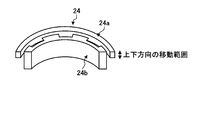
- FIG. FIG. 3 is a partial perspective view showing the non-contact power transmission unit of the second embodiment of the electric discharge machining apparatus according to the present invention.
- the length in the vertical direction (rotational axis direction) of the spindle-side non-contact power transmission unit 24b is the rotating wheel-side non-contact power transmission unit 24a. Is sufficiently longer than the vertical movement range (stroke) of the spindle 13.
- the vertical length of the rotating wheel side non-contact power transmission unit 24a is made sufficiently longer than the vertical length of the spindle side non-contact power transmission unit 24b to be longer than the vertical movement range (stroke) of the spindle 13. May be.
- the non-contact power transmission unit 24 of the second embodiment even if the spindle 13 moves in the vertical direction (rotational axis direction), the facing area between the non-contact power transmission units 24a and 24b does not always increase or decrease. The transmission efficiency of rotational power does not fluctuate, and highly accurate control performance can be obtained.
- FIG. 4 is a partial perspective view showing the non-contact power transmission unit of the third embodiment of the electric discharge machining apparatus according to the present invention.
- the vertical lengths (rotational axis directions) of the spindle-side non-contact power transmission unit 34b and the rotating wheel-side non-contact power transmission unit 34a are as follows.
- the spindle 13 is sufficiently longer than the vertical movement range (stroke) of the spindle 13.
- the non-contact power transmission unit 34 of the third embodiment even if the spindle 13 moves in the vertical direction, the rate of change in the facing area between the non-contact power transmission units 34a and 34b is small, so the transmission efficiency of the rotational power Hardly fluctuates, and highly accurate control performance can be obtained.
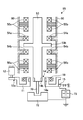
- FIG. FIG. 5 is a longitudinal sectional view schematically showing Embodiment 4 of the electric discharge machining apparatus according to the present invention.
- the same parts as those of the electric discharge machining apparatus 91 of the first embodiment shown in FIG. 1 are denoted by the same reference numerals, and detailed description thereof is omitted.
- the rotating wheel 11 and the spindle 53 are electrically connected by a slack conducting wire.
- the spindle 53 of the electric discharge machining apparatus 95 is formed in a long cylindrical shape, and has a disk portion 53 b in the middle portion.
- An upper and lower drive upper coil 54 a is disposed coaxially with the spindle 53 on the upper side of the disc portion 53 b.
- a lower coil 54b for vertical driving is arranged coaxially with the spindle 53 below the disk portion 53b.
- an upper left coil 55a is disposed on the left side of the spindle 53 with the coil axis orthogonal to the axis of the spindle 53.
- an upper right coil 55b is arranged on the right side of the spindle 53 with the coil axis orthogonal to the axis of the spindle 53.
- an upper front coil (not shown) is disposed on the front side of the spindle 53 with the coil axis orthogonal to the axis of the spindle 53.
- an upper rear coil (not shown) is disposed on the rear side of the spindle 53 with the coil axis orthogonal to the axis of the spindle 53.
- a lower left coil 56a is disposed on the left side of the spindle 53 with the coil axis orthogonal to the axis of the spindle 53.
- a lower right coil 56b is arranged on the right side of the spindle 53 with the coil axis orthogonal to the axis of the spindle 53.
- a lower front coil (not shown) is disposed on the front side of the spindle 53 with the coil axis orthogonal to the axis of the spindle 53 on the lower front side of the spindle 53.
- a lower rear coil (not shown) is disposed on the rear side of the spindle 53 with the coil axis orthogonal to the axis of the spindle 53.
- the vertical position of the spindle 53 can be controlled by adjusting the current flowing through the upper and lower drive upper coils 54a and 54b.
- the current of the upper and lower drive upper coil 54a is increased, the spindle 53 moves upward, and when the current of the lower and upper drive lower coil 54a is increased, the spindle 53 moves downward.
- the position of the upper part of the spindle 53 in the left-right direction can be controlled. Further, by adjusting the current flowing through the upper front coil and the upper rear coil (not shown), the position of the upper portion of the spindle 53 in the front-rear direction can be controlled.
- the position of the lower part of the spindle 53 in the left-right direction can be controlled.
- the current flowing in the lower front coil and the lower rear coil (not shown), the position of the lower portion of the spindle 53 in the front-rear direction can be controlled.
- Detection values of an unillustrated vertical position sensor, upper left / right position sensor, upper front / rear position sensor, lower left / right position sensor, and lower front / rear position sensor are input to a CPU (not illustrated), and the vertical position, left / right front / rear position, and tilt commanded by the spindle 53 are input.
- the current of the ten coils is controlled through a power amplifier (not shown) so as to be in the posture.
- the mass of the drive unit (spindle 53) is small, and there is almost no external force such as frictional force. Therefore, the spindle 53 is rotated and translated (in the direction of the rotation axis or rotation). High-speed and high-accuracy drive control is possible in all directions (perpendicular to the axis).
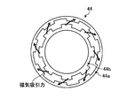
- FIG. FIG. 6 is a top view showing the non-contact power transmission unit of the fifth embodiment of the electric discharge machining apparatus according to the present invention
- FIG. 7 is a partial perspective view showing the non-contact power transmission unit of the fifth embodiment. .
- the upper part of the non-contact power transmission unit 44 a on the rotating wheel side is S.
- the upper and lower sides of an annular permanent magnet 44am as a pole are fixedly sandwiched between annular magnetic bodies 44aj having a plurality of (eight) projections 44at on the spindle side.
- the spindle-side non-contact power transmission unit 44b sandwiches the upper and lower sides of an annular permanent magnet 44bm whose upper part is an N pole with an annular magnetic body 44bj having a plurality of (eight) projections 44bt on the rotating wheel side. It is fixed.
- the spindle-side non-contact power transmission unit 44b is disposed below the rotating wheel-side non-contact power transmission unit 44a.
- the non-contact power transmission unit 44 transmits the power of the rotating wheel 11 to the spindle 53 and generates a magnetic attraction force that attracts the spindle 53 upward.
- the spindle 53 can be prevented from descending due to gravity.
- the length of the electric discharge machining apparatus 95 in the vertical direction can be shortened.
- the electric discharge machining apparatus is useful as a device capable of controlling the spindle in the horizontal and vertical directions with high accuracy.
Landscapes
- Chemical & Material Sciences (AREA)
- Chemical Kinetics & Catalysis (AREA)
- Electrochemistry (AREA)
- Engineering & Computer Science (AREA)
- Mechanical Engineering (AREA)
- Electrical Discharge Machining, Electrochemical Machining, And Combined Machining (AREA)
Abstract
ベース80にベアリング19を介して回転自在に支持された回転輪11と、前記ベース80に設置され動力伝達部12aを介して前記回転輪11を回転させる回転駆動装置12と、前記回転輪11の中央孔内に該回転輪11と略同心に配置され放電電極70を保持するスピンドル13と、前記回転輪11から前記スピンドル13へ非接触で回転動力を伝達する非接触動力伝達部14と、前記回転輪11に接触して該回転輪11に放電電力を供給する接触給電部15と、前記回転輪11と前記スピンドル13とを電気的に接続する弛み導線16と、を備える。
Description
本発明は、電極と工作物の間に電圧を印加し、両者の極間に放電を発生させることにより、工作物の除去加工を行う放電加工装置に関し、特に、回転する電極に対する電力の供給に関するものである。
従来の放電加工装置は、電極が回転するときに、電極又は電極を保持するスピンドルに接触している給電ブラシやベアリングを介して電極へ電力を供給している(例えば、特許文献1参照)。
また、内部に搭載したモータにより、ベースに非接触な状態で支持されているスピンドルの回転動力を得ている(例えば、特許文献2参照)。
しかしながら、上記特許文献1に記載された従来の放電加工装置は、電極へ電力を供給するために、回転するスピンドルにブラシやベアリングを接触させている。そのため、摩擦力の作用により、スピンドルの回転軸方向やそれに垂直な方向への動作速度、応答周波数が減じられる、という問題があった。さらに、スピンドルの制御系に、回転に同期した変動を発生させ、高精度な制御性能が得られない、という問題があった。
また、上記特許文献2に記載された従来の放電加工装置は、内部に搭載したモータにより回転動力を発生させている。そのため、内部に熱がこもり、スピンドルの膨張や制御性能の悪化等により、高精度な制御性能を得ることが困難であった。また、十分な回転動力を発生させるために、装置を回転軸方向に長くする必要がある、という問題があった。さらに、摩擦力の作用により、スピンドルの回転軸方向やそれに垂直な方向への動作速度、応答周波数が減じられる、という問題があった。
本発明は、上記に鑑みてなされたものであって、スピンドルへの摩擦力の作用がなく、モータの熱がこもることのない放電加工装置を得ることを目的とする。
上述した課題を解決し、目的を達成するために、本発明は、ベースにベアリングを介して回転自在に支持された回転輪と、前記ベースに設置され動力伝達部を介して前記回転輪を回転させる回転駆動装置と、前記回転輪の中央孔内に該回転輪と略同心に配置され放電電極を保持するスピンドルと、前記回転輪から前記スピンドルへ非接触で回転動力を伝達する非接触動力伝達部と、前記回転輪に接触して該回転輪に放電電力を供給する接触給電部と、前記回転輪と前記スピンドルとを電気的に接続する弛み導線と、を備えることを特徴とする。
本発明にかかる放電加工装置は、回転駆動装置からスピンドルへの水平、垂直方向の外乱を大幅に抑制し、殆んど回転動力のみをスピンドルに伝達するため、スピンドルを水平、垂直方向に高精度に制御することができる。また、回転駆動装置で発生した回転ムラを平滑化することができ、スピンドルを滑らかに回転させることができる、という効果を奏する。
また、回転駆動装置を外部に設置するので、ベースやスピンドルの回転軸方向の長さを短くすることができる。さらに、回転駆動装置から出る熱がスピンドルに殆んど伝わらないので、スピンドルの熱膨張や熱変形による制御性能の悪化や、ベアリングのグリス寿命の低下を防いで高精度な制御性能を長期間維持することができる、という効果を奏する。
以下に、本発明にかかる放電加工装置の実施の形態を図面に基づいて詳細に説明する。なお、この実施の形態によりこの発明が限定されるものではない。
実施の形態1.
図1は、本発明にかかる放電加工装置の実施の形態1を模式的に示す縦断面図であり、図2は、実施の形態1の放電加工装置の非接触動力伝達部を示す上面図である。
図1は、本発明にかかる放電加工装置の実施の形態1を模式的に示す縦断面図であり、図2は、実施の形態1の放電加工装置の非接触動力伝達部を示す上面図である。
図1に示すように、実施の形態1の放電加工装置91は、ベース80にベアリング19を介して回転自在に支持された回転輪11と、ベース80に設置されピニオン12bとギア12cとから成る動力伝達部12aを介して回転輪11を回転させる回転駆動装置としてのモータ12と、ベース80に設置された上下駆動装置17に回転継ぎ手18を介して回転自在に懸架され、回転輪11の中央孔内に回転輪11と略同心に配置され放電電極70を保持するスピンドル13と、回転輪11からスピンドル13へ非接触で動力を伝達する非接触動力伝達部14と、回転輪11に接触して放電電力を供給する接触給電部15と、回転輪11とスピンドル13とを電気的に接続する弛み導線16と、を備えている。上下駆動装置17は、ボールねじ、リニアモータ等のリニアアクチュエータにより構成されている。
スピンドル13は、回転輪11及び非接触動力伝達部14により非接触で回転駆動され、上下駆動装置17により上下駆動される。回転輪11の中央孔には回転輪側非接触動力伝達部14aが設けられ、回転輪側非接触動力伝達部14aに対向する部位のスピンドル13の外周部には、スピンドル側非接触動力伝達部14bが設けられ、回転輪11の回転動力をスピンドル13に伝達する。
図2に示すように、回転輪側非接触動力伝達部14aは、環状に形成された所謂ハルバッハ配列の多極界磁磁極であり、22.5°の角度範囲で径方向外向きに磁束を発生するように磁化された複数(4個)の主磁極磁石14anと、主磁極磁石14anと22.5°離間して22.5°の角度範囲で径方向内向きに磁束を発生するように磁化された複数(4個)の主磁極磁石14asと、主磁極磁石14an、14as間の22.5°の角度範囲で周方向の主磁極磁石14as向きに磁束を発生するように磁化された複数(8個)のヨーク磁石14ayと、から成っている。
スピンドル側非接触動力伝達部14bは、回転輪側に、複数(8個)の主磁極磁石14an、14asに対向する複数の突起14btを有する環状に形成された磁性体である。図2に示すように、主磁極磁石14an、14asと突起14btとの間には、磁気吸引力が発生しているので、回転輪11(回転輪側非接触動力伝達部14a)が回転すると、これに同期してスピンドル13(スピンドル側非接触動力伝達部14b)が回転する。
主磁極磁石14an、14asの磁束密度や、磁極数及び突起14btの数を適宜調整することにより、非接触動力伝達部14a、14bの上下方向長さを長くしないでも、スピンドル13が回転輪11と同期回転するのに必要な動力を伝達することができる。しかしながら、磁気吸引力を必要以上に大きくすると、回転輪11の上下振動や回転ムラがスピンドル13へ伝わりスピンドル13の制御性能を悪化させるので、その点、注意が必要である。
図1に示すように、回転輪11の導電部11aとスピンドル13の導電部13aとを電気的に接続する弛み導線16は、柔軟性があり、垂れ下がる(弛む)程度に十分長いものにしている。スピンドル13には、放電電極70がチャックされている。放電電極70は、加工槽71内に設置された工作物72に対向している。
接触給電部15は、ベース80に反力をとるばねにより回転輪11の導電部11aに押圧されており、回転輪11が回転しても、接触給電部15と回転輪11の導電部11aとは、常に電気的に接続されている。加工電源73が、接触給電部15、回転輪11、弛み導線16及びスピンドル13を介して放電電極70と工作物72の間に電圧を印加する。
スピンドル13は、動力源12、17に、回転継ぎ手18及び弛み導線16のみを介して接続されているため、回転動力を伝達するときに、上下方向の摩擦力を受けない。それ故、上下方向の負荷が小さくなり、高速な駆動制御が可能になる。また、外乱を殆んど受けないので、高精度な駆動制御が可能になる。
また、回転用のモータ12をベース80の外側に設置しているので、スピンドル13の長さを短くすることができる。さらに、回転用のモータ12をベース80の外側に設置しているので、スピンドル13への直接的な熱伝達がなく、スピンドル13の熱膨張による制御性能の悪化がなく、回転継ぎ手18のグリス寿命を延ばし、制御性能を長期間維持することができる。
実施の形態2.
図3は、本発明にかかる放電加工装置の実施の形態2の非接触動力伝達部を示す部分斜視図である。図3に示すように、実施の形態2の非接触動力伝達部24においては、スピンドル側非接触動力伝達部24bの上下方向(回転軸方向)長さが、回転輪側非接触動力伝達部24aの上下方向長さよりも、スピンドル13の上下方向の移動範囲(ストローク)以上に十分に長くなっている。なお、回転輪側非接触動力伝達部24aの上下方向長さを、スピンドル側非接触動力伝達部24bの上下方向長さよりも、スピンドル13の上下方向の移動範囲(ストローク)以上に十分に長くしてもよい。
図3は、本発明にかかる放電加工装置の実施の形態2の非接触動力伝達部を示す部分斜視図である。図3に示すように、実施の形態2の非接触動力伝達部24においては、スピンドル側非接触動力伝達部24bの上下方向(回転軸方向)長さが、回転輪側非接触動力伝達部24aの上下方向長さよりも、スピンドル13の上下方向の移動範囲(ストローク)以上に十分に長くなっている。なお、回転輪側非接触動力伝達部24aの上下方向長さを、スピンドル側非接触動力伝達部24bの上下方向長さよりも、スピンドル13の上下方向の移動範囲(ストローク)以上に十分に長くしてもよい。
実施の形態2の非接触動力伝達部24によれば、スピンドル13が上下方向(回転軸方向)に移動しても、常に、非接触動力伝達部24aと24bとの対向面積が増減しないので、回転動力の伝達効率が変動することはなく、高精度な制御性能が得られる。
実施の形態3.
図4は、本発明にかかる放電加工装置の実施の形態3の非接触動力伝達部を示す部分斜視図である。図4に示すように、実施の形態3の非接触動力伝達部34においては、スピンドル側非接触動力伝達部34b及び回転輪側非接触動力伝達部34aの上下方向(回転軸方向)長さは、スピンドル13の上下方向の移動範囲(ストローク)以上に十分に長くなっている。
図4は、本発明にかかる放電加工装置の実施の形態3の非接触動力伝達部を示す部分斜視図である。図4に示すように、実施の形態3の非接触動力伝達部34においては、スピンドル側非接触動力伝達部34b及び回転輪側非接触動力伝達部34aの上下方向(回転軸方向)長さは、スピンドル13の上下方向の移動範囲(ストローク)以上に十分に長くなっている。
実施の形態3の非接触動力伝達部34によれば、スピンドル13が上下方向に移動しても、非接触動力伝達部34aと34bとの対向面積の変化割合が小さいので、回転動力の伝達効率は、殆んど変動することはなく、高精度な制御性能が得られる。
実施の形態4.
図5は、本発明にかかる放電加工装置の実施の形態4を模式的に示す縦断面図である。図5に示す実施の形態4の放電加工装置95において、図1に示す実施の形態1の放電加工装置91と同等の部分は、同一の符号を付し、その詳細な説明を省略する。なお、図示はしないが、回転輪11とスピンドル53とは、弛み導線により電気的に接続されている。
図5は、本発明にかかる放電加工装置の実施の形態4を模式的に示す縦断面図である。図5に示す実施の形態4の放電加工装置95において、図1に示す実施の形態1の放電加工装置91と同等の部分は、同一の符号を付し、その詳細な説明を省略する。なお、図示はしないが、回転輪11とスピンドル53とは、弛み導線により電気的に接続されている。
図5に示すように、実施の形態4の放電加工装置95のスピンドル53は、長い円柱状に形成され、中間部に円板部53bを有している。円板部53bの上側には、上下駆動用上側コイル54aが、スピンドル53と同軸に配置されている。円板部53bの下側には、上下駆動用下側コイル54bが、スピンドル53と同軸に配置されている。
スピンドル53の上部左側には、上部左側コイル55aが、コイル軸をスピンドル53の軸に直交させてスピンドル53の左側に配置されている。スピンドル53の上部右側には、上部右側コイル55bが、コイル軸をスピンドル53の軸に直交させてスピンドル53の右側に配置されている。
スピンドル53の上部前側には、上部前側コイル(図示せず)が、コイル軸をスピンドル53の軸に直交させてスピンドル53の前側に配置されている。スピンドル53の上部後側には、上部後側コイル(図示せず)が、コイル軸をスピンドル53の軸に直交させてスピンドル53の後側に配置されている。
スピンドル53の下部左側には、下部左側コイル56aが、コイル軸をスピンドル53の軸に直交させてスピンドル53の左側に配置されている。スピンドル53の下部右側には、下部右側コイル56bが、コイル軸をスピンドル53の軸に直交させてスピンドル53の右側に配置されている。
スピンドル53の下部前側には、下部前側コイル(図示せず)が、コイル軸をスピンドル53の軸に直交させてスピンドル53の前側に配置されている。スピンドル53の下部後側には、下部後側コイル(図示せず)が、コイル軸をスピンドル53の軸に直交させてスピンドル53の後側に配置されている。
上下駆動用上側コイル54aと上下駆動用下側コイル54bに流れる電流を調整することにより、スピンドル53の上下方向の位置を制御することができる。上下駆動用上側コイル54aの電流を増加させるとスピンドル53が上方へ移動し、上下駆動用下側コイル54aの電流を増加させるとスピンドル53が下方へ移動する。
上部左側コイル55aと上部右側コイル55bに流れる電流を調整することにより、スピンドル53の上部の左右方向の位置を制御することができる。また、図示しない上部前側コイルと上部後側コイルに流れる電流を調整することにより、スピンドル53の上部の前後方向の位置を制御することができる。
また、下部左側コイル56aと下部右側コイル56bに流れる電流を調整することにより、スピンドル53の下部の左右方向の位置を制御することができる。また、図示しない下部前側コイルと下部後側コイルに流れる電流を調整することにより、スピンドル53の下部の前後方向の位置を制御することができる。
図示しない上下位置センサ、上部左右位置センサ、上部前後位置センサ、下部左右位置センサ、下部前後位置センサの検出値を図示しないCPUに入力し、スピンドル53が指令された上下位置、左右前後位置及び傾斜姿勢となるように、図示しないパワーアンプを介して上記10個のコイルの電流を制御する。
実施の形態4の放電加工装置95は、駆動部(スピンドル53)の質量が小さく、また、摩擦力など外部から受ける力が殆んどないので、スピンドル53を回転、並進(回転軸方向や回転軸に垂直な方向)全てにおいて、高速かつ高精度な駆動制御が可能である。
実施の形態5.
図6は、本発明にかかる放電加工装置の実施の形態5の非接触動力伝達部を示す上面図であり、図7は、実施の形態5の非接触動力伝達部を示す部分斜視図である。
図6は、本発明にかかる放電加工装置の実施の形態5の非接触動力伝達部を示す上面図であり、図7は、実施の形態5の非接触動力伝達部を示す部分斜視図である。
図6及び図7に示すように、実施の形態4の放電加工装置95に用いられる実施の形態5の非接触動力伝達部44においては、回転輪側非接触動力伝達部44aは、上部がS極となった環状の永久磁石44amの上下を、スピンドル側に複数(8個)の突起44atを有する環状の磁性体44ajで挟んで固着して成る。
また、スピンドル側非接触動力伝達部44bは、上部がN極となった環状の永久磁石44bmの上下を、回転輪側に複数(8個)の突起44btを有する環状の磁性体44bjで挟んで固着して成る。また、スピンドル側非接触動力伝達部44bは、回転輪側非接触動力伝達部44aよりも下に配置されている。
実施の形態5の非接触動力伝達部44によれば、非接触動力伝達部44が、回転輪11の動力をスピンドル53に伝達するとともに、スピンドル53を上方へ吸引する磁気吸引力を発生するので、重力によりスピンドル53が下降するのを防止することができる。また、重力補償のための部材を別途設ける必要がないので、放電加工装置95の上下方向の長さを短くすることができる。
以上のように、本発明にかかる放電加工装置は、スピンドルを水平、垂直方向に高精度に制御することができるものとして有用である。
11 回転輪
11a 導電部
12 モータ(回転駆動装置)
12a 動力伝達部
12b ピニオン
12c ギア
13 スピンドル
13a 導電部
14 非接触動力伝達部
14a 回転輪側非接触動力伝達部
14an,14as 主磁極磁石
14ay ヨーク磁石
14b スピンドル側非接触動力伝達部
14bt 突起
15 接触給電部
16 弛み導線
17 上下駆動装置(直動用モータ)
18 回転継ぎ手
19 ベアリング
24 非接触動力伝達部
24a 回転輪側非接触動力伝達部
24b スピンドル側非接触動力伝達部
34 非接触動力伝達部
34a 回転輪側非接触動力伝達部
34b スピンドル側非接触動力伝達部
44 非接触動力伝達部
44a 回転輪側非接触動力伝達部
44aj 磁性体
44at 突起
44am 永久磁石
44b スピンドル側非接触動力伝達部
44bj 磁性体
44bt 突起
44bm 永久磁石
53 スピンドル
53b 円板部
54a 上下駆動用上側コイル
54b 上下駆動用下側コイル
55a 上部左側コイル
55b 上部右側コイル
56a 下部左側コイル
56b 下部右側コイル
70 放電電極
71 加工槽
72 工作物
73 加工電源
80 ベース
91,95 放電加工装置
11a 導電部
12 モータ(回転駆動装置)
12a 動力伝達部
12b ピニオン
12c ギア
13 スピンドル
13a 導電部
14 非接触動力伝達部
14a 回転輪側非接触動力伝達部
14an,14as 主磁極磁石
14ay ヨーク磁石
14b スピンドル側非接触動力伝達部
14bt 突起
15 接触給電部
16 弛み導線
17 上下駆動装置(直動用モータ)
18 回転継ぎ手
19 ベアリング
24 非接触動力伝達部
24a 回転輪側非接触動力伝達部
24b スピンドル側非接触動力伝達部
34 非接触動力伝達部
34a 回転輪側非接触動力伝達部
34b スピンドル側非接触動力伝達部
44 非接触動力伝達部
44a 回転輪側非接触動力伝達部
44aj 磁性体
44at 突起
44am 永久磁石
44b スピンドル側非接触動力伝達部
44bj 磁性体
44bt 突起
44bm 永久磁石
53 スピンドル
53b 円板部
54a 上下駆動用上側コイル
54b 上下駆動用下側コイル
55a 上部左側コイル
55b 上部右側コイル
56a 下部左側コイル
56b 下部右側コイル
70 放電電極
71 加工槽
72 工作物
73 加工電源
80 ベース
91,95 放電加工装置
Claims (6)
- ベースにベアリングを介して回転自在に支持された回転輪と、
前記ベースに設置され動力伝達部を介して前記回転輪を回転させる回転駆動装置と、
前記回転輪の中央孔内に該回転輪と略同心に配置され放電電極を保持するスピンドルと、
前記回転輪から前記スピンドルへ非接触で回転動力を伝達する非接触動力伝達部と、
前記回転輪に接触して該回転輪に放電電力を供給する接触給電部と、
前記回転輪と前記スピンドルとを電気的に接続する弛み導線と、
を備えることを特徴とする放電加工装置。 - 前記回転駆動装置を前記ベースの外側に設置していることを特徴とする請求項1に記載の放電加工装置。
- 前記非接触動力伝達部は、磁気吸引力により、非接触で回転動力を伝達することを特徴とする請求項1に記載の放電加工装置。
- 前記非接触動力伝達部の環状の回転輪側非接触動力伝達部と環状のスピンドル側非接触動力伝達部の少なくとも一方の回転軸方向の長さが、前記スピンドルのストロークより長いことを特徴とする請求項1に記載の放電加工装置。
- 前記スピンドルが、磁気吸引力により、前記ベースに非接触で支持されていることを特徴とする請求項1に記載の放電加工装置。
- 前記非接触動力伝達部は、前記スピンドルを上方へ吸引する磁気吸引力を発生することを特徴とする請求項4に記載の放電加工装置。
Priority Applications (1)
| Application Number | Priority Date | Filing Date | Title |
|---|---|---|---|
| JP2010512996A JP5202624B2 (ja) | 2008-05-20 | 2009-05-14 | 放電加工装置 |
Applications Claiming Priority (2)
| Application Number | Priority Date | Filing Date | Title |
|---|---|---|---|
| JP2008132196 | 2008-05-20 | ||
| JP2008-132196 | 2008-05-20 |
Publications (1)
| Publication Number | Publication Date |
|---|---|
| WO2009142140A1 true WO2009142140A1 (ja) | 2009-11-26 |
Family
ID=41340073
Family Applications (1)
| Application Number | Title | Priority Date | Filing Date |
|---|---|---|---|
| PCT/JP2009/059002 Ceased WO2009142140A1 (ja) | 2008-05-20 | 2009-05-14 | 放電加工装置 |
Country Status (2)
| Country | Link |
|---|---|
| JP (1) | JP5202624B2 (ja) |
| WO (1) | WO2009142140A1 (ja) |
Cited By (1)
| Publication number | Priority date | Publication date | Assignee | Title |
|---|---|---|---|---|
| CN102218575A (zh) * | 2011-05-23 | 2011-10-19 | 广东工业大学 | 一种微细电解及微细电火花加工机床的主轴系统 |
Families Citing this family (1)
| Publication number | Priority date | Publication date | Assignee | Title |
|---|---|---|---|---|
| DE102019211287B4 (de) * | 2019-07-30 | 2021-05-20 | Sauer Gmbh | Vorsatzspindelvorrichtung zum Einsatz an einer Werkzeugmaschine, System mit Werkzeugmaschine und Vorsatzspindelvorrichtung und Verfahren zum Steuern eines mit einer Vorsatzspindelvorrichtung durchgeführten Bohrprozesses, sowie ein Computerprogrammprodukt |
Citations (2)
| Publication number | Priority date | Publication date | Assignee | Title |
|---|---|---|---|---|
| JP2000218438A (ja) * | 1999-01-26 | 2000-08-08 | Mitsutoyo Corp | 放電加工機 |
| JP2007223016A (ja) * | 2006-02-27 | 2007-09-06 | Sodick Co Ltd | スピンドル装置 |
-
2009
- 2009-05-14 WO PCT/JP2009/059002 patent/WO2009142140A1/ja not_active Ceased
- 2009-05-14 JP JP2010512996A patent/JP5202624B2/ja active Active
Patent Citations (2)
| Publication number | Priority date | Publication date | Assignee | Title |
|---|---|---|---|---|
| JP2000218438A (ja) * | 1999-01-26 | 2000-08-08 | Mitsutoyo Corp | 放電加工機 |
| JP2007223016A (ja) * | 2006-02-27 | 2007-09-06 | Sodick Co Ltd | スピンドル装置 |
Cited By (1)
| Publication number | Priority date | Publication date | Assignee | Title |
|---|---|---|---|---|
| CN102218575A (zh) * | 2011-05-23 | 2011-10-19 | 广东工业大学 | 一种微细电解及微细电火花加工机床的主轴系统 |
Also Published As
| Publication number | Publication date |
|---|---|
| JPWO2009142140A1 (ja) | 2011-09-29 |
| JP5202624B2 (ja) | 2013-06-05 |
Similar Documents
| Publication | Publication Date | Title |
|---|---|---|
| CN101489717B (zh) | 回转工作台的支承和驱动装置 | |
| CN105164568B (zh) | 扫描设备 | |
| KR101397060B1 (ko) | 반발력 보상장치 | |
| CN104493606B (zh) | 加工机床及其基于磁致伸缩的精密进给驱动装置 | |
| JP2008254114A (ja) | 工作機械用磁気軸受スピンドル装置 | |
| JP6848306B2 (ja) | エンコーダ装置、駆動装置、ステージ装置、ロボット装置、及びエンコーダ装置の取り付け方法 | |
| JP6459754B2 (ja) | モータ | |
| KR20110102713A (ko) | 자기베어링 구조 및 이를 구비한 터보기기 | |
| JP2018189426A (ja) | エンコーダ装置、駆動装置、ステージ装置、及びロボット装置 | |
| JP5202624B2 (ja) | 放電加工装置 | |
| JP5868548B2 (ja) | ハイブリッド車両用回転電機のロータ保持構造 | |
| US20060043817A1 (en) | DC brush motor | |
| JP2009002464A (ja) | 磁気軸受装置およびこれを備えた工作機械 | |
| WO2007111031A1 (ja) | モータ及び駆動制御装置 | |
| JP5488131B2 (ja) | 電磁アクチュエータ | |
| JP5841172B2 (ja) | スパッタリング装置 | |
| US20050052965A1 (en) | Optical pickup and disc drive apparatus | |
| JP2005218203A (ja) | アクチュエータ及びボンディング装置 | |
| JP7499616B2 (ja) | ロボットアーム及び関節構造 | |
| JP2014033493A (ja) | 電動回転機 | |
| JPH10329926A (ja) | 振動フィーダ | |
| JP2007146911A (ja) | 振動抑制装置 | |
| CN206211805U (zh) | 直流电机 | |
| JP2011094744A (ja) | サスペンションおよび制振装置 | |
| JP2007051989A (ja) | 多回転式絶対値エンコーダ用発電装置及び発電装置を備えた多回転式絶対値エンコーダ |
Legal Events
| Date | Code | Title | Description |
|---|---|---|---|
| 121 | Ep: the epo has been informed by wipo that ep was designated in this application |
Ref document number: 09750502 Country of ref document: EP Kind code of ref document: A1 |
|
| WWE | Wipo information: entry into national phase |
Ref document number: 2010512996 Country of ref document: JP |
|
| NENP | Non-entry into the national phase |
Ref country code: DE |
|
| 122 | Ep: pct application non-entry in european phase |
Ref document number: 09750502 Country of ref document: EP Kind code of ref document: A1 |