WO2009139432A1 - 磁気探傷方法及び磁気探傷装置 - Google Patents
磁気探傷方法及び磁気探傷装置 Download PDFInfo
- Publication number
- WO2009139432A1 WO2009139432A1 PCT/JP2009/058969 JP2009058969W WO2009139432A1 WO 2009139432 A1 WO2009139432 A1 WO 2009139432A1 JP 2009058969 W JP2009058969 W JP 2009058969W WO 2009139432 A1 WO2009139432 A1 WO 2009139432A1
- Authority
- WO
- WIPO (PCT)
- Prior art keywords
- flaw
- signal
- current
- flaw detection
- candidate
- Prior art date
Links
Images


Classifications
-
- G—PHYSICS
- G01—MEASURING; TESTING
- G01N—INVESTIGATING OR ANALYSING MATERIALS BY DETERMINING THEIR CHEMICAL OR PHYSICAL PROPERTIES
- G01N27/00—Investigating or analysing materials by the use of electric, electrochemical, or magnetic means
- G01N27/72—Investigating or analysing materials by the use of electric, electrochemical, or magnetic means by investigating magnetic variables
- G01N27/82—Investigating or analysing materials by the use of electric, electrochemical, or magnetic means by investigating magnetic variables for investigating the presence of flaws
- G01N27/90—Investigating or analysing materials by the use of electric, electrochemical, or magnetic means by investigating magnetic variables for investigating the presence of flaws using eddy currents
- G01N27/9013—Arrangements for scanning
-
- G—PHYSICS
- G01—MEASURING; TESTING
- G01N—INVESTIGATING OR ANALYSING MATERIALS BY DETERMINING THEIR CHEMICAL OR PHYSICAL PROPERTIES
- G01N27/00—Investigating or analysing materials by the use of electric, electrochemical, or magnetic means
- G01N27/72—Investigating or analysing materials by the use of electric, electrochemical, or magnetic means by investigating magnetic variables
- G01N27/82—Investigating or analysing materials by the use of electric, electrochemical, or magnetic means by investigating magnetic variables for investigating the presence of flaws
- G01N27/90—Investigating or analysing materials by the use of electric, electrochemical, or magnetic means by investigating magnetic variables for investigating the presence of flaws using eddy currents
- G01N27/9046—Investigating or analysing materials by the use of electric, electrochemical, or magnetic means by investigating magnetic variables for investigating the presence of flaws using eddy currents by analysing electrical signals
Definitions
- magnetic flaw detection methods such as an eddy current flaw detection method and a leakage magnetic flux flaw detection method are known as methods for nondestructively detecting flaws existing in a material to be inspected such as a steel plate and a steel pipe.
- the eddy current flaw detection method is a flaw detection method that utilizes the fact that an eddy current induced by applying an alternating magnetic field to a material to be inspected is disturbed by a flaw.
- the leakage magnetic flux flaw detection method when a magnetic field is applied to a material to be inspected and magnetized, if there is a flaw that blocks the magnetic flux generated in the material to be inspected, the magnetic flux is generated at the site where the flaw is present. This is a flaw detection method that utilizes leakage into the surface space.
- a flaw signal to be detected (of a flaw detection signal detected by a predetermined detection sensor, when the direction of the magnetic field to be applied and the direction in which the magnetic field is applied forms a specific angle
- the amplitude of the signal obtained from the site where the flaw is present is maximized.
- the amplitude of the flaw signal in the leakage magnetic flux flaw detection method is maximized when the direction of the applied magnetic field (the direction of the magnetic flux in the material to be inspected) and the direction in which the flaw extends are orthogonal, and the direction of the magnetic field is the direction in which the flaw extends. Decreases as the position deviates from the direction perpendicular to.
- a rotating magnetic field in which the direction of the magnetic field changes from time to time is applied to the material to be inspected so that the direction in which the flaw extends can be detected (so that a flaw signal having a detectable amplitude can be obtained).
- a magnetic flaw detection method for detecting flaws extending in various directions based on a flaw detection signal generated by the rotating magnetic field has been proposed (for example, see Japanese Patent Application Laid-Open No. 2002-131285).
- an exciting coil as shown in FIG. 1 is used.
- the exciting coil 10 shown in FIG. 1 includes two exciting coils (X) arranged such that the winding directions of the conducting wires are orthogonal to each other (therefore, the generated magnetic fields are orthogonal to each other) and the center positions coincide with each other.
- a direction excitation coil 1 and a Y direction excitation coil 2) are provided. Then, the phase of the AC excitation current energized in each of the excitation coils 1 and 2 is shifted by 90 ° (for example, the X-direction excitation coil 1 is energized with a cosine wave excitation current, and the Y-direction excitation coil 2 is sinusoidal.
- the flaw signal is synchronized with an alternating excitation current. For this reason, by detecting the flaw detection signal synchronously using the excitation current as a reference signal and extracting a signal synchronized with the excitation current, it is possible to extract a signal that cannot have a high S / N ratio from the flaw detection signal.
- the AC signal extracted by the synchronous detection is smoothed by the low-pass filter in order to increase the ratio (S / N ratio) between the scratch signal and the noise generated randomly without being synchronized with the excitation current. Is common.
- the AC signal extracted by synchronous detection is smoothed for each unit region corresponding to about two to three periods of the reference signal (excitation current).
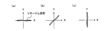
- FIG. 3 is a schematic diagram of a Lissajous waveform indicating that the flaw signal and the lift-off fluctuation noise have a phase difference.
- the flaw signal phase ⁇ d and the lift-off fluctuation noise phase ⁇ l are generally different.
- the XY coordinate system is rotated so that the lift-off fluctuation noise is along the X axis, and the signal component in the Y ′ axis direction in the rotated X′Y ′ coordinate system is used as the flaw detection signal.
- the phase analysis method it can be expected that the influence of lift-off fluctuation noise on the flaw detection ability can be suppressed.
- the phase analysis method is not limited to the method of rotating the XY coordinate system of the Lissajous waveform as described above, but only the amplitude of the signal component having a specific phase in the Lissajous waveform is evaluated and has other phases.
- a method of removing the amplitude of the signal component from the evaluation target is also included.
- the conventional magnetic flaw detection method using a rotating magnetic field has the following problems due to the use of a single-frequency excitation current. (1) Since the effect of synchronous detection cannot be obtained sufficiently, the flaw detection ability (S / N ratio) may be reduced. (2) It is impossible to estimate flaw angle information (in which direction it extends). (3) A general phase analysis method cannot be used as a technique for improving the flaw detection ability (S / N ratio) in the eddy current flaw detection method. (4) The continuity of the flaw cannot be accurately evaluated.
- the amplitude of the flaw signal detected is maximized.
- the amplitude of the flaw signal becomes zero when the deviation angle in the direction of the magnetic field from the direction in which the amplitude of the flaw signal is maximum exceeds ⁇ ⁇ °.
- the direction of the magnetic field rotates 360 ° during one period of the exciting current.
- ⁇ 20.
- the amplitude of the flaw signal in the leakage magnetic flux flaw detection method is maximized when the direction of the magnetic field to be applied and the extending direction are perpendicular to each other.
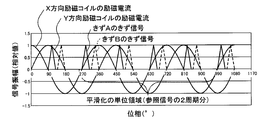
- FIG. 4 is a graph showing a time-series relationship between the excitation current waveform and the signal waveform under the above assumption.
- FIG. 5 shows a state in which a flaw detection signal including a flaw signal is synchronously detected using an excitation current as a reference signal, and a flaw signal extracted by the synchronous detection is smoothed for each unit region corresponding to two cycles of the reference signal.
- FIG. 5A is a graph showing a flaw signal waveform
- FIG. 5A shows a flaw signal waveform of flaw A
- FIG. 5B shows a flaw signal waveform of flaw B; 4 and 5, the waveform of noise included in the flaw detection signal is not shown.
- the excitation current supplied to the X-direction excitation coil 1 or the excitation current supplied to the Y-direction excitation coil 2 shown in FIG. 1 is used as a reference signal.
- the flaw signal obtained from flaws A and B has a shorter cycle than any excitation current. That is, since the period of the flaw signal and the period of the reference signal do not coincide with each other, the effect of synchronous detection (extracting a high S / N ratio from the flaw detection signal) cannot be sufficiently obtained, and flaw detection is performed. There is a concern that the performance may be reduced (problem (1) described above).
- the flaw signal extracted by the synchronous detection is smoothed for each unit region corresponding to two periods of the reference signal, as shown in FIG. 5, the phase information (flaw angle information of the flaw signal after smoothing) ) Will be lost, and for both flaws A and B, the flaw signal after smoothing will have the same DC signal waveform. That is, the angle information of the flaw cannot be estimated (problem (2) described above).
- a method that evaluates flaw continuity by grasping the two-dimensional distribution state of flaws from flaw detection images.
- a flaw detection signal (a grayscale image or a color image) obtained by imaging a flaw detection signal including a flaw signal or by imaging a signal obtained by binarizing the flaw detection signal with a predetermined threshold value.
- Image and visual inspection of the flaw detection image, or by performing image processing using an appropriate image processing filter or the like on the flaw detection image, to grasp the two-dimensional distribution state of the flaw, Assessing sex.
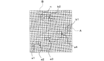
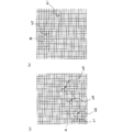
- the inspection object S includes two flaws A and B and a noise source N.
- FIG. 6 the flaw detection image obtained by scanning the detection sensor on the inspection material S (flaw detection image obtained by imaging the signal obtained by binarizing the flaw detection signal with a predetermined threshold value)
- FIG. the pixel group corresponding to the flaw candidate site in the material S to be inspected, which is discretized according to the A / D conversion speed, the scanning speed, etc. of the detection sensor, that is, the four pixel groups a1 corresponding to the flaw A
- the flaw detection image is formed based only on the amplitude information of the flaw detection signal, it is based only on the distribution state of the pixel group corresponding to the flaw candidate site. Therefore, continuity must be evaluated. Therefore, according to the configuration of the image processing filter or the like for evaluating the continuity of the flaws, as shown in FIG. 8, the pixel groups a1 to a4 and b1 are one flaw A, and the pixel groups b2 and n are 1 There is a risk of accidental evaluation that the damage is B.
- the length of flaw A is overestimated over the actual length, while the length of flaw B is underestimated over the actual length and corresponds to the noise source N.
- the pixel n may be mistakenly recognized as a flaw. For this reason, there exists a possibility that the harmfulness of a flaw cannot be evaluated correctly.
- the present invention is a magnetic flaw detection method for detecting a defect based on a flaw detection signal generated by a rotating magnetic field applied to a material to be inspected, for exciting the rotating magnetic field.
- an exciting current an alternating current in which a first current and a second current having a frequency lower than that of the first current are superimposed is used, and after the flaw detection signal is synchronously detected using the first current as a reference signal, the second current Extracting a flaw candidate signal by performing synchronous detection using a reference signal as a reference signal, and a flaw detection image composed of a plurality of pixels corresponding to each part of the inspection object, each pixel being a flaw candidate in each part
- an alternating current in which the first current and the second current having a frequency lower than that of the first current are superimposed is used. While the magnetic field generated by (and the eddy current induced by this magnetic field) predominantly acts on the material to be inspected, the second current having a low frequency mainly affects the direction of the generated magnetic field (and eddy current). It functions to rotate in the material to be inspected. This is because the induced electromotive force generated in the material to be inspected is proportional to the frequency of the excitation current.
- the phase information of the flaw signal is easily retained, so that the phase analysis method can be applied when performing synchronous detection using the second current as a reference signal, and the flaw detection capability is improved. It is possible to suppress the influence of lift-off fluctuation noise and the like.
- a flaw detection image composed of a plurality of pixels corresponding to each part of the material to be inspected, wherein each pixel is a flaw candidate signal (synchronous detection using the second current as a reference signal) in each part. (Including the case where the predetermined threshold value cannot be obtained and the candidate signal intensity is binarized), and the phase of the flaw candidate signal at each part can be identified.
- the detected flaw detection image is displayed. Specifically, for example, each pixel is colored differently according to the phase of the scratch candidate signal obtained by applying the phase analysis method (the density of each pixel varies depending on the strength of the scratch candidate signal). ) One color image is displayed as a flaw detection image.
- a plurality of grayscale images having different phases (phase ranges) of flaw candidate signals included in each image are displayed as flaw detection images. Become. For this reason, since not only the intensity
- the present invention is a magnetic flaw detection method for detecting a defect based on a flaw detection signal generated by a rotating magnetic field applied to a material to be inspected, and exciting the rotating magnetic field.
- an exciting current an alternating current obtained by superimposing a first current and a second current having a frequency lower than the first current is used, and after the flaw detection signal is synchronously detected using the first current as a reference signal, the first current
- a flaw detection image each of which includes a plurality of pixels corresponding to each part of the material to be inspected, and in which the pixel corresponding to the detected defect candidate part has a density distinguishable from other pixels.
- a step of forming a plurality of sheets according to the phase of a flaw candidate signal in the candidate part, and a flaw candidate in a flaw candidate part existing in each flaw detection image by individually performing image processing on each of the plurality of flaw detection images As a magnetic flaw detection method comprising the steps of evaluating the continuity of the flaw candidate site in the direction according to the phase of the signal, and detecting a flaw based on the continuity of the flaw candidate site Is also provided.
- the ratio between the frequency of the first current and the frequency of the second current may be determined as appropriate depending on the resolution at which the flaw angle information is estimated (the resolution increases as the ratio between the two increases). .
- the frequencies of the first current and the second current satisfy the following formula (1).
- the present invention provides a magnetizing unit that applies a rotating magnetic field to a material to be inspected, a detecting unit that detects a flaw detection signal generated by the rotating magnetic field, and a signal that performs signal processing on the flaw detection signal.
- a magnetic flaw detection apparatus including a processing unit, wherein the magnetizing unit includes an exciting coil that energizes an alternating current obtained by superimposing a first current and a second current having a frequency lower than the first current as an exciting current.
- the signal processing means includes first synchronous detection means for synchronously detecting the flaw detection signal detected by the detection means using the first current as a reference signal, and an output signal of the first synchronous detection means for the second current.
- Second synchronous detection means for extracting a flaw candidate signal that is synchronously detected as a reference signal and binarizing the flaw candidate signal with a predetermined threshold value to detect a flaw candidate portion in the inspection object
- a flaw detection image having a density at which each pixel corresponding to the detected defect candidate part has a density distinguishable from other pixels, each of which is composed of a candidate part detection means and a plurality of pixels corresponding to each part of the material to be inspected.
- a flaw detection image forming means for forming a plurality of flaws according to the phase of a flaw candidate signal at the flaw candidate portion, and flaws present in each flaw detection image by individually performing image processing on each of the plurality of flaw detection images.
- a continuity evaluating means for evaluating the continuity of the flaw candidate part in the direction corresponding to the phase of the flaw candidate signal in the candidate part, and a flaw detecting means for detecting a flaw based on the continuity of the flaw candidate part. It is provided as a magnetic flaw detector characterized by comprising.
- the frequencies of the first current and the second current satisfy the following formula (1).
- FIG. 1 is a plan view sectional view showing an example of an exciting coil for generating a rotating magnetic field.
- FIG. 2 is a schematic diagram illustrating an example of a Lissajous waveform.
- FIG. 3 is a schematic diagram of a Lissajous waveform indicating that the flaw signal and the lift-off fluctuation noise have a phase difference.
- FIG. 4 is a graph showing a time-series relationship between an excitation current waveform and a signal waveform in a conventional magnetic flaw detection method using a rotating magnetic field.
- FIG. 5 synchronously detects a flaw detection signal including a flaw signal using the excitation current shown in FIG.
- FIG. 6 is a diagram schematically showing flaws and noise sources present in the material to be inspected.
- FIG. 7 is a diagram schematically showing an example of a conventional flaw detection image obtained for the material to be inspected shown in FIG.
- FIG. 8 is a diagram showing the result of evaluating the continuity of the flaws for the flaw detection image shown in FIG.
- FIG. 9 is a block diagram showing a schematic configuration of a magnetic flaw detector according to an embodiment of the present invention.
- FIG. 10 is a schematic external view of the flaw detection probe shown in FIG. FIG.
- FIG. 11 is a graph showing signal waveforms generated by the magnetizing means shown in FIG.
- FIG. 12 is a graph schematically showing an example of a flaw signal waveform detected by the detecting means shown in FIG.
- FIG. 13 shows the first synchronous detection means shown in FIG. 9 that detects flaw detection signals including a flaw signal using the first current as a reference signal, and detects the flaw signal extracted by the synchronous detection for two cycles of the reference signal. It is a graph which shows typically an example of a flaw signal waveform after smoothing for every unit field to do.
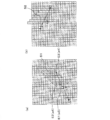
- 14 is a diagram schematically illustrating an example of a flaw detection image formed by the flaw detection image forming unit illustrated in FIG. 9 with respect to the inspection target material illustrated in FIG. FIG.
- FIG. 15 is a diagram illustrating an evaluation method performed by the continuity evaluation unit shown in FIG. 9 for the flaw detection image shown in FIG.
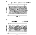
- FIGS. 16A and 16B are explanatory diagrams for explaining the outline of the flaw detection test according to the embodiment of the present invention.
- FIG. 16A is a longitudinal sectional view and FIG. 16B is a plan view.
- FIG. 17 shows a Lissajous waveform of a flaw signal obtained by the flaw detection test shown in FIG.
- FIG. 9 is a block diagram showing a schematic configuration of a magnetic flaw detector according to one embodiment of the present invention.
- FIG. 10 is a schematic external view of the flaw detection probe shown in FIG.
- a magnetic flaw detector 100 according to this embodiment includes a magnetizing unit 1 that applies a rotating magnetic field to a material to be inspected, a detecting unit 2 that detects a flaw detection signal generated by the rotating magnetic field, and the flaw detection signal. And signal processing means 3 for performing signal processing.
- the magnetizing means 1 includes an exciting coil 11 that energizes an exciting current for generating a rotating magnetic field.
- the excitation coil 11 includes an X-direction excitation coil 111 and a Y-direction excitation coil 112 that are arranged so that the winding directions of the conducting wires are orthogonal to each other and the center positions coincide with each other.
- an excitation current X direction excitation current
- a magnetic field is generated in the X direction shown in FIG.
- a magnetic field is generated in the Y direction shown in FIG. 10 by energizing the Y direction exciting coil 112 with an exciting current (Y direction exciting current).
- the exciting coil 11 is characterized in that an alternating current in which a first current and a second current having a frequency lower than the first current are superimposed is energized as an exciting current.
- the X direction excitation coil 111 is supplied with an X direction excitation current obtained by superimposing the first current and the second current
- the Y direction excitation coil 112 is supplied with a first current and a second current.
- a Y-direction excitation current that is superimposed and whose phase is shifted by 90 ° with respect to the X-direction excitation current is energized.
- the characteristic portion will be described more specifically with reference to FIG. 11 as appropriate.
- the predetermined ratio between the frequency of the first current and the frequency of the second current may be determined as appropriate depending on the resolution at which the flaw angle information is estimated.
- the ratio of the frequency of the first current / It is determined so as to satisfy the frequency of the second current ⁇ 8.
- the magnetizing means 1 has the first current and the first current having a frequency lower than that of the first current as the excitation current (X direction excitation current and Y direction excitation current) for exciting the rotating magnetic field. Since an alternating current superimposed with two currents is used, the magnetic field generated by the first current having a high frequency (and the eddy current induced by this magnetic field) predominantly acts on the material to be inspected, while the first having a low frequency.
- the two currents mainly function to rotate the direction of the generated magnetic field (and eddy current) in the inspection object.
- the detection means 2 is a detection coil for detecting a change in magnetic flux in the Z direction (see FIG. 10) that passes through the center of the excitation coil 11 and is orthogonal to the X direction and the Y direction.
- the detection coil 2 detects a change in the magnetic flux in the Z direction and outputs it to the signal processing means 3 as a flaw detection signal.
- the detection coil 2 is integrated with the X-direction excitation coil 111 and the Y-direction excitation coil 112 described above to form the flaw detection probe 4.
- the signal processing means 3 is a flaw detection image composed of a plurality of pixels corresponding to each part of the material to be inspected, and each pixel has a density according to the intensity of the flaw candidate signal in each part,
- a flaw detection image display means for displaying a flaw detection image in which the phase of the flaw candidate signal at each part can be identified.
- the flaw detection image display means 34 is a flaw detection image composed of a plurality of pixels corresponding to each part of the inspection object detected by the sensor, and each pixel has a density corresponding to the amplitude A in each part. Then, the flaw detection image in which the phase ⁇ at each part can be identified is displayed. For example, the flaw detection image display means 34 displays one color image in which each pixel is colored differently according to the phase ⁇ (the density of each pixel varies according to the amplitude A) as a flaw detection image. Alternatively, the flaw detection image display means 34 displays, as flaw detection images, a plurality of grayscale images (the density of each pixel varies depending on the amplitude A) having different phases ⁇ (phase ⁇ range) included in each image.
- the signal processing means 3 binarizes the flaw candidate signal with a predetermined threshold value, so that flaw candidate part detecting means 35 for detecting flaw candidate parts in the inspection material, and each part of the inspection material A plurality of flaw detection images each composed of a plurality of corresponding pixels and having a density at which the pixel corresponding to the detected flaw candidate part can be distinguished from other pixels according to the phase of the flaw candidate signal in the flaw candidate part
- Continuity evaluation means 37 for evaluating the continuity of the flaw candidate site
- flaw detection means 38 for detecting a flaw based on the continuity of the flaw candidate site.
- a flaw detection image having for example, a pixel corresponding to the detected flaw candidate site has a density of 255 and another pixel has a density of 0) according to the phase ⁇ (phase range) in the flaw candidate site
- the flaw detection image forming means 36 forms two flaw detection images in which the range of the phase ⁇ at the flaw candidate site is 0 ° ⁇ ⁇ ⁇ 45 ° and 135 ° ⁇ ⁇ ⁇ 180 °, respectively.
- FIG. 14 is a diagram schematically showing an example of a flaw detection image formed by the flaw detection image forming means 36 for the inspection material S shown in FIG. 6, and FIG. 14 (a) shows the phase ⁇ at the flaw candidate site.
- FIG. 14 is a diagram schematically showing an example of a flaw detection image formed by the flaw detection image forming means 36 for the inspection material S shown in FIG. 6, and FIG. 14 (a) shows the phase ⁇ at the flaw candidate site.
- FIG. 14B shows a flaw detection image in which the range of the phase ⁇ at the flaw candidate site is 135 ° ⁇ ⁇ ⁇ 180 °.
- the four pixel groups a1 to a4 corresponding to the flaw A are accurately included as flaw candidate sites, and the flaw detection image shown in FIG. 14B corresponds to the flaw B.
- the two pixel groups b1 and b2 are accurately included as flaw candidate parts.
- the flaw candidate portion corresponding to the noise source N has a phase ⁇ of 45 ° ⁇ ⁇ ⁇ 135 °, and therefore a flaw detection image is not formed.
- the other pixels and the target pixel E1 are pixel regions for the same flaw candidate part.
- the target pixel E1 and the other pixels E2 and E3 are determined to be pixel regions for the same flaw candidate part.
- the continuity evaluation means 37 repeats the above processing using all pixels constituting the flaw candidate site in each flaw detection image as the target pixel, and as a result, the continuity evaluation means 37 Is calculated.
- the phase ⁇ range (135 ° ⁇ ⁇ ⁇ 180 °) in the flaw detection image shown in FIG. 14B is the same as the phase ⁇ range (0 ° ⁇ ⁇ ⁇ 45 °) in the flaw detection image shown in FIG.
- the neighboring pixel region shown in FIG. 15B (the hatched region S2 in the figure) is different from the neighboring pixel region shown in FIG.
- a flaw detection test of a linear artificial flaw F formed on the steel sheet S was performed using the magnetic flaw detection apparatus 100 whose schematic configuration is shown in FIGS. 9 and 10.
- Table 1 shows the outline of the flaw detection conditions
- Table 2 shows the outline specifications of the material to be inspected.
- the flaw detection probe 4 an X-direction and Y-direction excitation coil wound 50 times on each side of a core material that is a cube with a side of 6 mm, and a diameter of 5 mm attached to the bottom surface of the core material And a 100-turn detection coil.
Landscapes
- Chemical & Material Sciences (AREA)
- Chemical Kinetics & Catalysis (AREA)
- Electrochemistry (AREA)
- Physics & Mathematics (AREA)
- Health & Medical Sciences (AREA)
- Life Sciences & Earth Sciences (AREA)
- Analytical Chemistry (AREA)
- Biochemistry (AREA)
- General Health & Medical Sciences (AREA)
- General Physics & Mathematics (AREA)
- Immunology (AREA)
- Pathology (AREA)
- Investigating Or Analyzing Materials By The Use Of Magnetic Means (AREA)
Priority Applications (5)
| Application Number | Priority Date | Filing Date | Title |
|---|---|---|---|
| CN2009801173715A CN102027364B (zh) | 2008-05-15 | 2009-05-14 | 磁探伤方法以及磁探伤装置 |
| US12/992,618 US8466674B2 (en) | 2008-05-15 | 2009-05-14 | Magnetic testing method and magnetic testing apparatus |
| CA2722844A CA2722844C (en) | 2008-05-15 | 2009-05-14 | Magnetic testing method and magnetic testing apparatus |
| EP09746638.7A EP2282199B1 (en) | 2008-05-15 | 2009-05-14 | Magnetic flaw detecting method and magnetic flaw detection device |
| BRPI0912722-4A BRPI0912722B1 (pt) | 2008-05-15 | 2009-05-14 | Método de ensaio magnético e aparelhagem de ensaio magnético |
Applications Claiming Priority (2)
| Application Number | Priority Date | Filing Date | Title |
|---|---|---|---|
| JP2008128523A JP4863127B2 (ja) | 2008-05-15 | 2008-05-15 | 磁気探傷方法及び磁気探傷装置 |
| JP2008-128523 | 2008-05-15 |
Publications (1)
| Publication Number | Publication Date |
|---|---|
| WO2009139432A1 true WO2009139432A1 (ja) | 2009-11-19 |
Family
ID=41318796
Family Applications (1)
| Application Number | Title | Priority Date | Filing Date |
|---|---|---|---|
| PCT/JP2009/058969 WO2009139432A1 (ja) | 2008-05-15 | 2009-05-14 | 磁気探傷方法及び磁気探傷装置 |
Country Status (8)
| Country | Link |
|---|---|
| US (1) | US8466674B2 (pt) |
| EP (1) | EP2282199B1 (pt) |
| JP (1) | JP4863127B2 (pt) |
| CN (1) | CN102027364B (pt) |
| AR (1) | AR071797A1 (pt) |
| BR (1) | BRPI0912722B1 (pt) |
| CA (1) | CA2722844C (pt) |
| WO (1) | WO2009139432A1 (pt) |
Cited By (3)
| Publication number | Priority date | Publication date | Assignee | Title |
|---|---|---|---|---|
| WO2011158098A1 (en) * | 2010-06-17 | 2011-12-22 | Toyota Jidosha Kabushiki Kaisha | Eddy current sensor and eddy current measurement method |
| CN105548350A (zh) * | 2016-01-26 | 2016-05-04 | 江苏理工学院 | 基于圆角矩形阵列探头的脉冲涡流缺陷检测成像系统 |
| CN110646507A (zh) * | 2019-09-26 | 2020-01-03 | 东北大学 | 基于锁相放大的多频旋转磁场的金属缺陷检测装置及方法 |
Families Citing this family (14)
| Publication number | Priority date | Publication date | Assignee | Title |
|---|---|---|---|---|
| JP5660911B2 (ja) * | 2011-01-28 | 2015-01-28 | 三菱航空機株式会社 | 雷電流検出センサ |
| US9291599B2 (en) * | 2011-08-18 | 2016-03-22 | Nippon Steel & Sumitomo Metal Corporation | Magnetic testing method and apparatus |
| JP5931889B2 (ja) * | 2011-09-26 | 2016-06-08 | 株式会社東芝 | 渦電流探傷装置および渦電流探傷方法 |
| US9267921B2 (en) * | 2012-06-29 | 2016-02-23 | Zetec, Inc. | Axial and circumferential flaw sensing eddy current probe |
| CN102768238A (zh) * | 2012-08-01 | 2012-11-07 | 上海海事大学 | 一种多激励高灵敏度的电磁探伤传感装置 |
| US10101301B2 (en) * | 2015-03-24 | 2018-10-16 | Board Of Trustees Of Michigan State University | Rotating field transceiver nondestructive inspection probe |
| JP6506122B2 (ja) * | 2015-07-09 | 2019-04-24 | 株式会社日立ハイテクノロジーズ | レール検査装置、および、レール検査システム |
| JP6601226B2 (ja) * | 2016-01-12 | 2019-11-06 | 日本製鉄株式会社 | 漏洩磁束探傷装置 |
| JP6697302B2 (ja) * | 2016-03-25 | 2020-05-20 | マークテック株式会社 | 探傷装置、及び探傷装置による欠陥検出方法 |
| EP3953700B1 (en) * | 2019-04-11 | 2024-04-24 | TDW Delaware, Inc. | Pipeline tool with composite magnetic field for inline inspection |
| EP3961203B1 (en) * | 2019-04-24 | 2022-11-30 | JFE Steel Corporation | Leakage magnetic flux flaw inspection device |
| CN110889830B (zh) * | 2019-11-13 | 2023-03-24 | 河南科技大学 | 基于三维漏磁彩色成像的钢丝绳损伤检测方法及检测系统 |
| CN112345629A (zh) * | 2020-10-23 | 2021-02-09 | 新疆大学 | 一种新型h结构脉冲涡流聚焦探头 |
| CN113311061B (zh) * | 2021-04-20 | 2024-07-16 | 中国神华能源股份有限公司国华电力分公司 | 检测探头、受热面管的裂纹检测方法 |
Citations (4)
| Publication number | Priority date | Publication date | Assignee | Title |
|---|---|---|---|---|
| JPS62145162A (ja) * | 1985-12-19 | 1987-06-29 | Nippon Steel Corp | 分割型回転磁界渦流探傷装置 |
| JPH0266446A (ja) * | 1988-08-31 | 1990-03-06 | Sumitomo Metal Ind Ltd | 表面欠陥検査方法 |
| JP2002131285A (ja) | 2000-10-26 | 2002-05-09 | Univ Nihon | 溶接線、溶接突合せ部の位置・方向の検知用プローブ、検知装置、及び検知方法 |
| JP2005164516A (ja) * | 2003-12-05 | 2005-06-23 | Mitsubishi Heavy Ind Ltd | 欠陥検知方法 |
Family Cites Families (2)
| Publication number | Priority date | Publication date | Assignee | Title |
|---|---|---|---|---|
| EP0228473B1 (en) * | 1985-07-03 | 1992-01-22 | Nippon Steel Corporation | Apparatus for non-destructively inspecting flaw of metal materials utilizing magnetic field |
| JP4911489B2 (ja) * | 2005-01-07 | 2012-04-04 | 財団法人電力中央研究所 | 探傷装置 |
-
2008
- 2008-05-15 JP JP2008128523A patent/JP4863127B2/ja active Active
-
2009
- 2009-05-14 AR ARP090101747A patent/AR071797A1/es active IP Right Grant
- 2009-05-14 CN CN2009801173715A patent/CN102027364B/zh not_active Expired - Fee Related
- 2009-05-14 EP EP09746638.7A patent/EP2282199B1/en not_active Not-in-force
- 2009-05-14 US US12/992,618 patent/US8466674B2/en active Active
- 2009-05-14 BR BRPI0912722-4A patent/BRPI0912722B1/pt not_active IP Right Cessation
- 2009-05-14 WO PCT/JP2009/058969 patent/WO2009139432A1/ja active Application Filing
- 2009-05-14 CA CA2722844A patent/CA2722844C/en not_active Expired - Fee Related
Patent Citations (4)
| Publication number | Priority date | Publication date | Assignee | Title |
|---|---|---|---|---|
| JPS62145162A (ja) * | 1985-12-19 | 1987-06-29 | Nippon Steel Corp | 分割型回転磁界渦流探傷装置 |
| JPH0266446A (ja) * | 1988-08-31 | 1990-03-06 | Sumitomo Metal Ind Ltd | 表面欠陥検査方法 |
| JP2002131285A (ja) | 2000-10-26 | 2002-05-09 | Univ Nihon | 溶接線、溶接突合せ部の位置・方向の検知用プローブ、検知装置、及び検知方法 |
| JP2005164516A (ja) * | 2003-12-05 | 2005-06-23 | Mitsubishi Heavy Ind Ltd | 欠陥検知方法 |
Cited By (6)
| Publication number | Priority date | Publication date | Assignee | Title |
|---|---|---|---|---|
| WO2011158098A1 (en) * | 2010-06-17 | 2011-12-22 | Toyota Jidosha Kabushiki Kaisha | Eddy current sensor and eddy current measurement method |
| US8593137B2 (en) | 2010-06-17 | 2013-11-26 | Toyota Jidosha Kabushiki Kaisha | Eddy current sensor and eddy current measurement method |
| CN105548350A (zh) * | 2016-01-26 | 2016-05-04 | 江苏理工学院 | 基于圆角矩形阵列探头的脉冲涡流缺陷检测成像系统 |
| CN105548350B (zh) * | 2016-01-26 | 2018-12-25 | 江苏理工学院 | 基于圆角矩形阵列探头的脉冲涡流缺陷检测成像系统 |
| CN110646507A (zh) * | 2019-09-26 | 2020-01-03 | 东北大学 | 基于锁相放大的多频旋转磁场的金属缺陷检测装置及方法 |
| CN110646507B (zh) * | 2019-09-26 | 2022-11-08 | 东北大学 | 基于锁相放大的多频旋转磁场的金属缺陷检测装置及方法 |
Also Published As
| Publication number | Publication date |
|---|---|
| JP2009276232A (ja) | 2009-11-26 |
| US8466674B2 (en) | 2013-06-18 |
| BRPI0912722B1 (pt) | 2019-05-07 |
| EP2282199A4 (en) | 2013-07-17 |
| CA2722844C (en) | 2013-11-12 |
| EP2282199A1 (en) | 2011-02-09 |
| EP2282199B1 (en) | 2018-07-11 |
| AR071797A1 (es) | 2010-07-14 |
| US20110163741A1 (en) | 2011-07-07 |
| CN102027364A (zh) | 2011-04-20 |
| CA2722844A1 (en) | 2009-11-19 |
| BRPI0912722A2 (pt) | 2015-10-13 |
| JP4863127B2 (ja) | 2012-01-25 |
| CN102027364B (zh) | 2012-05-30 |
Similar Documents
| Publication | Publication Date | Title |
|---|---|---|
| JP4863127B2 (ja) | 磁気探傷方法及び磁気探傷装置 | |
| Wu et al. | Composite magnetic flux leakage detection method for pipelines using alternating magnetic field excitation | |
| JP4998821B2 (ja) | 渦流検査方法及び該渦流検査方法を実施するための渦流検査装置 | |
| JP5522699B2 (ja) | パルス磁気を用いた非破壊検査装置及び非破壊検査方法 | |
| JP4835995B2 (ja) | 漏洩磁束探傷法及び漏洩磁束探傷装置 | |
| JP2011133268A (ja) | 探傷装置及び探傷方法 | |
| JP4766472B1 (ja) | 非破壊検査装置及び非破壊検査方法 | |
| JP2003240761A (ja) | 磁性金属被検体の表層欠陥又は表面欠陥の検出方法及び装置 | |
| EP2818856B1 (en) | Eddy-current inspection method and device | |
| Zhang et al. | Mechanism study for directivity of TR probe when applying Eddy current testing to ferro-magnetic structural materials | |
| JP2011069623A (ja) | 渦電流探傷方法 | |
| JP2006177952A (ja) | 渦電流プローブ、検査システム及び検査方法 | |
| JPH0335624B2 (pt) | ||
| JP2017067743A (ja) | 非破壊検査装置及び非破壊検査方法 | |
| Peng et al. | A novel differential excitation capacitive sensing for hydrogen pipeline inspection | |
| WO2006113504A2 (en) | Near fieldtm and combination near fieldtm - remote field electromagnetic testing (et) probes for inspecting ferromagnetic pipes and tubes such as those used in heat exchangers | |
| Zheng et al. | Processing methods of the pipeline crack detection signal by a balanced field electromagnetic technique based on phase characteristics | |
| JP5611863B2 (ja) | 渦電流探傷装置、方法、及びプログラム | |
| JP6776676B2 (ja) | 信号処理装置及び信号処理方法 | |
| JP6170005B2 (ja) | 渦電流探傷方法及び渦電流探傷装置 | |
| RU2548944C1 (ru) | Способ неразрушающего контроля изделий | |
| KR101138359B1 (ko) | 경사진 전자기장을 발생시키는 비파괴 검사 장치 | |
| JP2009287981A (ja) | 渦電流探傷装置と渦電流探傷方法 | |
| JP2005164298A (ja) | 渦流探傷方法及び装置 | |
| Hedengren et al. | Information fusion methods for coupled eddy-current sensors |
Legal Events
| Date | Code | Title | Description |
|---|---|---|---|
| WWE | Wipo information: entry into national phase |
Ref document number: 200980117371.5 Country of ref document: CN |
|
| 121 | Ep: the epo has been informed by wipo that ep was designated in this application |
Ref document number: 09746638 Country of ref document: EP Kind code of ref document: A1 |
|
| WWE | Wipo information: entry into national phase |
Ref document number: 2722844 Country of ref document: CA |
|
| WWE | Wipo information: entry into national phase |
Ref document number: 4277/KOLNP/2010 Country of ref document: IN |
|
| NENP | Non-entry into the national phase |
Ref country code: DE |
|
| WWE | Wipo information: entry into national phase |
Ref document number: 2009746638 Country of ref document: EP |
|
| WWE | Wipo information: entry into national phase |
Ref document number: 12992618 Country of ref document: US |
|
| ENP | Entry into the national phase |
Ref document number: PI0912722 Country of ref document: BR Kind code of ref document: A2 Effective date: 20101112 |