WO2009139186A1 - カメラシステム - Google Patents
カメラシステム Download PDFInfo
- Publication number
- WO2009139186A1 WO2009139186A1 PCT/JP2009/002151 JP2009002151W WO2009139186A1 WO 2009139186 A1 WO2009139186 A1 WO 2009139186A1 JP 2009002151 W JP2009002151 W JP 2009002151W WO 2009139186 A1 WO2009139186 A1 WO 2009139186A1
- Authority
- WO
- WIPO (PCT)
- Prior art keywords
- lens
- interchangeable lens
- period
- camera
- synchronization signal
- Prior art date
Links
Images

Classifications
-
- G—PHYSICS
- G03—PHOTOGRAPHY; CINEMATOGRAPHY; ANALOGOUS TECHNIQUES USING WAVES OTHER THAN OPTICAL WAVES; ELECTROGRAPHY; HOLOGRAPHY
- G03B—APPARATUS OR ARRANGEMENTS FOR TAKING PHOTOGRAPHS OR FOR PROJECTING OR VIEWING THEM; APPARATUS OR ARRANGEMENTS EMPLOYING ANALOGOUS TECHNIQUES USING WAVES OTHER THAN OPTICAL WAVES; ACCESSORIES THEREFOR
- G03B17/00—Details of cameras or camera bodies; Accessories therefor
- G03B17/02—Bodies
- G03B17/12—Bodies with means for supporting objectives, supplementary lenses, filters, masks, or turrets
- G03B17/14—Bodies with means for supporting objectives, supplementary lenses, filters, masks, or turrets interchangeably
-
- G—PHYSICS
- G03—PHOTOGRAPHY; CINEMATOGRAPHY; ANALOGOUS TECHNIQUES USING WAVES OTHER THAN OPTICAL WAVES; ELECTROGRAPHY; HOLOGRAPHY
- G03B—APPARATUS OR ARRANGEMENTS FOR TAKING PHOTOGRAPHS OR FOR PROJECTING OR VIEWING THEM; APPARATUS OR ARRANGEMENTS EMPLOYING ANALOGOUS TECHNIQUES USING WAVES OTHER THAN OPTICAL WAVES; ACCESSORIES THEREFOR
- G03B13/00—Viewfinders; Focusing aids for cameras; Means for focusing for cameras; Autofocus systems for cameras
- G03B13/32—Means for focusing
- G03B13/34—Power focusing
- G03B13/36—Autofocus systems
-
- H—ELECTRICITY
- H04—ELECTRIC COMMUNICATION TECHNIQUE
- H04N—PICTORIAL COMMUNICATION, e.g. TELEVISION
- H04N23/00—Cameras or camera modules comprising electronic image sensors; Control thereof
- H04N23/60—Control of cameras or camera modules
- H04N23/66—Remote control of cameras or camera parts, e.g. by remote control devices
- H04N23/663—Remote control of cameras or camera parts, e.g. by remote control devices for controlling interchangeable camera parts based on electronic image sensor signals
-
- H—ELECTRICITY
- H04—ELECTRIC COMMUNICATION TECHNIQUE
- H04N—PICTORIAL COMMUNICATION, e.g. TELEVISION
- H04N23/00—Cameras or camera modules comprising electronic image sensors; Control thereof
- H04N23/60—Control of cameras or camera modules
- H04N23/67—Focus control based on electronic image sensor signals
- H04N23/673—Focus control based on electronic image sensor signals based on contrast or high frequency components of image signals, e.g. hill climbing method
-
- G—PHYSICS
- G03—PHOTOGRAPHY; CINEMATOGRAPHY; ANALOGOUS TECHNIQUES USING WAVES OTHER THAN OPTICAL WAVES; ELECTROGRAPHY; HOLOGRAPHY
- G03B—APPARATUS OR ARRANGEMENTS FOR TAKING PHOTOGRAPHS OR FOR PROJECTING OR VIEWING THEM; APPARATUS OR ARRANGEMENTS EMPLOYING ANALOGOUS TECHNIQUES USING WAVES OTHER THAN OPTICAL WAVES; ACCESSORIES THEREFOR
- G03B2205/00—Adjustment of optical system relative to image or object surface other than for focusing
- G03B2205/0007—Movement of one or more optical elements for control of motion blur
Definitions
- the present invention relates to a camera system, and more particularly to a camera system including an interchangeable lens and a camera body.
- Patent Document 1 discloses a camera system including a camera body and an interchangeable lens. This camera system performs autofocus control at the time of capturing a still image by transmitting a command for controlling the driving of the interchangeable lens from the camera body to the interchangeable lens while synchronizing the camera body and the interchangeable lens.
- the camera system has a through image display function for displaying an image captured by the image sensor on a liquid crystal display provided on the back of the camera body.
- a through image display function for displaying an image captured by the image sensor on a liquid crystal display provided on the back of the camera body.
- ⁇ ⁇ Control is required between the camera body and the interchangeable lens when displaying a through image or capturing a moving image.
- an autofocus operation is necessary.
- the focus lens is finely advanced and retracted in the optical axis direction. For this reason, it is necessary to finely control the operation of the lens from the camera body to the interchangeable lens (wobbling control).
- Patent Document 1 does not disclose how to synchronize the camera body and the interchangeable lens when displaying a through image or capturing a moving image.
- the present invention uses a synchronizing signal of a predetermined frequency when generating a through image or capturing a moving image, and synchronizes the camera body and the interchangeable lens, while wobbling the frequency of the wobbling operation of the focus lens. It is an object to provide a camera system that can be controlled at an appropriate frequency.
- a camera system including a camera body and an interchangeable lens.
- the camera body captures the subject image formed by the interchangeable lens at a predetermined imaging cycle, generates image data, and body control unit generates a synchronization signal having a first cycle correlated with the imaging cycle.
- transmission means for transmitting the generated synchronization signal to the interchangeable lens.
- the body control unit further transmits information indicating a second cycle different from the first cycle to the interchangeable lens via the transmission unit.
- the interchangeable lens includes a focus lens, a drive unit that drives the focus lens along the optical axis, a reception unit that receives information indicating the synchronization signal and the second period transmitted from the camera body, and an operation of the interchangeable lens.
- Lens control means for controlling.
- the lens control unit controls the driving unit to drive the focus lens minutely along the optical axis in the second cycle, and performs control different from the minute advance / retreat drive in the interchangeable lens in the first cycle. .
- a camera system including a camera body and an interchangeable lens.
- the camera body captures a subject image formed by the interchangeable lens at a predetermined imaging cycle, generates an image data to generate image data, and generates a first synchronization signal having a first cycle correlated with the imaging cycle.
- Body control means and transmission means for transmitting the generated synchronization signal to the interchangeable lens.
- the body control means generates a second synchronization signal having the second period and transmits it to the interchangeable lens.
- the interchangeable lens controls the operation of the focus lens, drive means for driving the focus lens along the optical axis, receiving means for receiving the first and second synchronization signals transmitted from the camera body, and the interchangeable lens.
- Lens control means controls the driving unit to drive the position of the focus lens minutely along the optical axis according to the second synchronization signal, and is different from the minute advance / retreat driving within the interchangeable lens in the first period. I do.
- a camera body to which an interchangeable lens can be attached captures the subject image formed by the interchangeable lens at a predetermined imaging cycle, generates image data, and body control unit generates a synchronization signal having a first cycle correlated with the imaging cycle. And transmission means for transmitting the generated synchronization signal to the interchangeable lens.
- the body control means further transmits information indicating a second period, which is a period for driving the focus lens to be advanced and retracted minutely along the optical axis and is different from the first period, to the interchangeable lens via the transmission means.
- an interchangeable lens that can be attached to a camera body.
- the interchangeable lens includes a focus lens, drive means for driving the focus lens along the optical axis, a synchronization signal having a first period transmitted from the camera body, and information indicating a second period different from the first period.
- Receiving means, and lens control means for controlling the operation of the interchangeable lens.
- the lens control unit controls the driving unit to drive the focus lens minutely along the optical axis in the second cycle, and performs control different from the minute advance / retreat drive in the interchangeable lens in the first cycle.
- a synchronization signal having a predetermined frequency is used to synchronize the camera body and the interchangeable lens, and the frequency of the wobbling operation of the focus lens is determined.
- a camera system that can be controlled at a frequency suitable for wobbling can be provided.
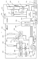
- FIG. 1 is a block diagram of a camera system according to a first embodiment.
- Flow chart for explaining switching between synchronous mode and asynchronous mode Timing chart for explaining the synchronization state Flow chart for explaining wobbling control Timing chart for explaining the synchronization state
- FIG. 1 is a block diagram illustrating a configuration of a camera system according to a first embodiment.
- the camera system 1 includes a camera body 100 and an interchangeable lens 200 that can be attached to and detached from the camera body 100.
- the camera system 1 can generate moving image data by periodically capturing image data with the CCD image sensor 110.
- the present invention relates to an interchangeable lens camera system.
- the present invention is an invention made to accurately synchronize a camera body and an interchangeable lens when generating a through image or capturing a moving image.
- the camera body 100 includes a CCD image sensor 110, a liquid crystal monitor 120, a camera controller 140, a body mount 150, a power source 160, and a card slot 170.
- the camera controller 140 controls the entire camera system 1 such as the CCD image sensor 110 in response to an instruction from an operation member such as the release button 130.
- the camera controller 140 transmits a vertical synchronization signal to the timing generator 112.
- the camera controller 140 generates an exposure synchronization signal based on the vertical synchronization signal.
- the camera controller 140 periodically and repeatedly transmits the generated exposure synchronization signal to the lens controller 240 via the body mount 150 and the lens mount 250.
- the camera controller 140 uses the DRAM 141 as a work memory during control operations and image processing operations.
- the CCD image sensor 110 captures a subject image incident through the interchangeable lens 200 and generates image data.
- the generated image data is digitized by the AD converter 111.
- the image data digitized by the AD converter 111 is subjected to various image processing by the camera controller 140.
- the various image processings referred to here include, for example, image compression processing such as gamma correction processing, white balance correction processing, scratch correction processing, YC conversion processing, electronic zoom processing, and JPEG compression processing.
- the CCD image sensor 110 operates at a timing controlled by the timing generator 112.
- the operation of the CCD image sensor 110 includes a still image capturing operation, a moving image capturing operation, a through image capturing operation, and the like.
- the through image is an image that is not recorded on the memory card 171 after image capturing.
- the through image is mainly a moving image, and is displayed on the liquid crystal monitor 120 in order to determine a composition for capturing a still image.
- the liquid crystal monitor 120 displays an image indicated by the display image data processed by the camera controller 140.
- the liquid crystal monitor 120 can selectively display both moving images and still images.
- a memory card 171 can be mounted in the card slot 170.
- the card slot 170 controls the memory card 171 based on the control from the camera controller 140.
- the memory card 171 can store image data generated by image processing of the camera controller 140.
- the memory card 171 can store a JPEG image file.
- the memory card 171 can output image data or an image file stored therein.
- the image data or image file output from the memory card 171 is subjected to image processing by the camera controller 140.
- the camera controller 140 decompresses the image data or image file acquired from the memory card 171 and generates display image data.
- the power source 160 supplies power for consumption by the camera system 1.
- the power source 160 may be, for example, a dry battery or a rechargeable battery. Moreover, the power supplied from the outside by the power cord may be supplied to the camera system 1.
- the body mount 150 can be mechanically and electrically connected to the lens mount 250 of the interchangeable lens 200.
- the body mount 150 can transmit and receive data to and from the interchangeable lens 200 via the lens mount 250.
- the body mount 150 transmits the exposure synchronization signal received from the camera controller 140 to the lens controller 240 via the lens mount 250. Further, other control signals received from the camera controller 140 are transmitted to the lens controller 240 via the lens mount 250. For example, information related to driving of the focus lens 230 received from the camera controller 140 is transmitted to the lens controller 240 via the lens mount 250.
- the body mount 150 transmits a signal received from the lens controller 240 via the lens mount 250 to the camera controller 140.
- the body mount 150 supplies the power received from the power supply 160 to the entire interchangeable lens 200 via the lens mount 250.
- the interchangeable lens 200 includes an optical system, a lens controller 240, and a lens mount 250.
- the optical system of the interchangeable lens 200 includes a zoom lens 210, an OIS lens 220, a diaphragm 260, and a focus lens 230.
- the zoom lens 210 is a lens for changing the magnification of a subject image formed by the optical system of the interchangeable lens 200.
- the zoom lens 210 is composed of one or a plurality of lenses.
- the drive mechanism 211 includes a zoom ring or the like that can be operated by the user, transmits the operation by the user to the zoom lens 210, and moves the zoom lens 210 along the optical axis direction of the optical system.
- the detector 212 detects the drive amount in the drive mechanism 211.
- the lens controller 240 can grasp the zoom magnification in the optical system by acquiring the detection result in the detector 212.
- the OIS lens 220 is a lens for correcting blurring of a subject image formed by the optical system of the interchangeable lens 200.
- the OIS lens 220 moves in a direction that cancels out the blur of the camera system 1, thereby reducing the blur of the subject image on the CCD image sensor 110.
- the OIS lens 220 is composed of one or a plurality of lenses.
- the actuator 221 drives the OIS lens 220 in a plane perpendicular to the optical axis of the optical system under the control of the OIS IC 223.
- the actuator 221 can be realized by a magnet and a flat coil, for example.
- the position detection sensor 222 is a sensor that detects the position of the OIS lens 220 in a plane perpendicular to the optical axis of the optical system.
- the position detection sensor 222 can be realized by a magnet and a Hall element, for example.
- the OIS IC 223 controls the actuator 221 based on the detection result of the position detection sensor 222 and the detection result of a shake detector such as a gyro sensor.
- the OIS IC 223 obtains the detection result of the shake detector from the lens controller 240. Further, the OIS IC 223 transmits a signal indicating the state of the optical image blur correction process to the lens controller 240.
- the diaphragm 260 is a member for adjusting the amount of light passing through the optical system.
- the diaphragm 260 includes, for example, a plurality of diaphragm blades, and the amount of light can be adjusted by opening and closing an opening formed by the blades.
- the diaphragm motor 261 is a driving unit for opening and closing the opening of the diaphragm 260.
- the focus lens 230 is a lens for changing the focus state of the subject image formed on the CCD image sensor 110 by the optical system.
- the focus lens 230 is composed of one or a plurality of lenses.
- the focus motor 233 drives the focus lens 230 to advance and retract along the optical axis of the optical system based on the control of the lens controller 240. Thereby, the focus state of the subject image formed on the CCD image sensor 110 by the optical system can be changed.
- a stepping motor is used in the first embodiment.
- the present invention is not limited to this. For example, it can be realized by a DC motor, a linear motor, an ultrasonic motor, or the like.
- the lens controller 240 controls the entire interchangeable lens 200 such as the OIS IC 223 and the focus motor 233 based on the control signal from the camera controller 140.
- the lens controller 240 controls the focus motor 233 based on a control signal from the camera controller 140 so that the focus lens 230 is advanced and retracted along the optical axis by a predetermined driving method.
- the lens controller 240 can perform wobbling control of the focus lens 230 in synchronization with the exposure synchronization signal from the camera controller 140 in the autofocus operation.
- the wobbling control of the focus lens 230 is to drive the focus lens 230 minutely forward and backward on the optical axis. This minute advance / retreat drive is performed in a predetermined cycle.
- the lens controller 240 can perform wobbling control of the focus lens 230 at a frequency different from the frequency of the exposure synchronization signal acquired from the camera controller 140.
- the lens controller 240 receives signals from the detector 212, the OIS IC 223, and the like, and transmits them to the camera controller 140.
- the lens controller 240 exchanges commands and data with the camera controller 140 via the lens mount 250 and the body mount 150.
- the lens controller 240 uses the DRAM 241 as a work memory at the time of control.
- the flash memory 242 stores programs and parameters used when the lens controller 240 is controlled.
- the lens controller 240 is a focus lens at a frequency different from the frequency of the exposure synchronization signal acquired from the camera controller 140. 230 wobbling control can be performed. Therefore, the flash memory 242 of the present embodiment stores information indicating the relationship between the frequency at which the lens controller 240 can cause the focus lens 230 to perform a wobbling operation and the frequency of the exposure synchronization signal acquired from the camera controller 140. As a result, the wobbling operation can be controlled at a frequency independent of other controls.
- the flash memory 242 relates to the ratio of the frequency of the wobbling operation that can be controlled by the lens controller 240 (hereinafter referred to as “wobbling frequency”) to the frequency of the exposure synchronization signal periodically acquired from the camera controller 140.
- the flash memory 242 also stores information regarding the frequency at which the lens controller 240 can cause the focus lens 230 to perform a wobbling operation.
- the camera controller 140 transmits an exposure synchronization signal to the lens controller 240 at 60 (Hz). Further, it is assumed that the lens controller 240 can drive the focus lens 230 at a frequency of 1/2 and 1/4 of the exposure synchronization signal. Further, it is assumed that the lens controller 240 can operate the focus lens 230 at 30 (Hz) and 15 (Hz).
- the flash memory 242 stores information indicating that wobbling control can be performed at a frequency of 1/2 or 1/4 of the frequency of the exposure synchronization signal. The flash memory 242 stores information indicating that the focus lens 230 can be wobbling controlled at 30 (Hz) and 15 (Hz).
- the camera controller 140 is an example of a body-side control means.
- the body mount 150 is an example of a transmission unit.
- the lens mount 250 is an example of a receiving unit.
- the lens controller 240 is an example of a lens control unit.
- the CCD image sensor 110 is an example of an imaging unit.
- the focus motor 233 is an example of a driving unit.
- the flash memory 242 is an example of a storage unit.
- the interchangeable lens 200 does not synchronize with the synchronization mode that operates in synchronization with the exposure synchronization signal received from the camera body 100 (ie, generated within the interchangeable lens 200).
- Asynchronous mode that operates at the same timing. Whether the interchangeable lens 200 operates in the synchronous mode or the asynchronous mode is determined by the camera controller 140 according to the control state in the camera body 100.
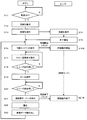
- FIG. 2 is a flowchart showing an operation example of the camera system related to the switching operation of the above-described synchronous mode / asynchronous mode.
- the operations of the camera controller 140 and the lens controller 240 in the switching operation of the synchronous mode / asynchronous mode will be described with reference to the flowchart of FIG.
- the camera controller 140 When the camera system is turned off and is switched on by a user operation or the like (S11), the camera controller 140 starts an initialization operation in the camera body 100 (S12) and the interchangeable lens 200. Is instructed to start the initialization operation (S13).
- the lens controller 240 receives an instruction from the camera controller 140 and performs an initialization operation in the interchangeable lens 200 (S14).
- the initialization operation in the interchangeable lens 200 includes various operations. For example, the origin measurement of the operation of the focus motor 233, the confirmation of the value of the counter 243, the loading of the program stored in the flash memory 242 to the DRAM 241 and the like. Can be mentioned.
- the lens controller 240 notifies the camera controller 140 to that effect (S15).
- the camera controller 140 shifts from the asynchronous mode to the synchronous mode (S16).
- the camera controller 140 transmits a synchronization start command to the lens controller 240.
- the lens controller 240 shifts from the asynchronous mode to the synchronous mode, and performs a control operation in synchronization with the synchronization signal received from the camera controller 140 (S16B).
- the lens controller 240 grasps the driving state of the focus motor 233 and the aperture motor 261 in synchronization with the synchronization signal, and transmits the result to the camera controller 140.
- the camera controller 140 proceeds to a through image generation and display operation (S17).
- a through image generation and display operation S17
- the camera controller 140 accurately grasps the position information of the focus lens 230, the aperture value of the aperture 260, and the like at a predetermined timing. can do.
- the camera system 1 can perform AF control and AE control with higher accuracy. The details of the through image and display operation will be described later.
- the camera controller 140 monitors whether the release button 130 is half-pressed (S18). When the release button 130 is pressed halfway, the camera controller 140 performs an autofocus operation and an automatic exposure control operation (S19). When these operations are completed, the release button 130 monitors whether or not a full-press operation has been performed (S20).
- the camera controller 140 shifts from the synchronous mode to the asynchronous mode (S21).
- the camera controller 140 transmits a synchronization end command to the lens controller 240.
- the lens controller 240 shifts to the asynchronous mode (S21B).
- the CCD image sensor 110 performs exposure (S22).
- the camera controller 140 reads image data generated by exposure from the CCD image sensor 110 and performs image processing (S23).
- the process returns to step S16, and the camera controller 140 shifts to the synchronous mode.
- the reason why the camera controller 140 shifts to the asynchronous mode at the start of image capturing (when the release button 130 is fully pressed) is that the camera controller 140 does not capture the image data until it is recorded on the memory card 171. This is because each processing unit in the camera body 100 may be controlled (processing of captured image data or recording to the memory card 171), and it is not necessary to synchronize with the lens controller 240. Thereby, the camera controller 140 can concentrate on the processing in the camera body 100.
- the camera controller 140 and the lens controller 240 are driven in an asynchronous mode.
- the camera controller 140 only needs to control each processing unit provided in the camera body 100 and does not need to control the processing unit in the lens controller 240. Because there is no need to take.
- the camera controller 140 can concentrate on reproducing the image data. As a result, the camera controller 140 can perform image data reproduction processing at high speed. Further, by driving in the asynchronous mode during reproduction, the power of the CCD image sensor 110 can be turned off during reproduction.
- the camera controller 140 and the lens controller 240 are driven in an asynchronous mode, so that the camera controller 140 does not need to transmit a synchronization signal to the lens controller 240.
- the power of the CCD image sensor 110 is turned off during the reproduction of the image data, thereby realizing power saving.
- the camera controller 140 shifts from the synchronous mode to the asynchronous mode.
- the camera controller 140 performs processing of captured image data or recording to the memory card 171
- the camera body 100 and the interchangeable lens 200 are not particularly synchronized. It is possible to concentrate on processing and recording of image data on the memory card 171.
- the camera controller 140 can process image data and record image data on the memory card 171 at high speed.
- the camera controller 140 when reproducing the image data recorded on the memory card 171, the camera controller 140 operates in an asynchronous mode. Thereby, the camera controller 140 can concentrate on reproduction
- the camera controller 140 shifts from the asynchronous mode to the synchronous mode, the camera controller 140 transmits a synchronization start command to the lens controller 240.
- the lens controller 240 performs a control operation in synchronization with the exposure synchronization signal received from the camera controller 140. Specifically, the driving state of the focus motor 233 and the aperture motor 261 is grasped in synchronization with the exposure synchronization signal, and the result is transmitted to the camera controller 140.
- the camera controller 140 notifies the lens controller 240 of the command to switch between the synchronous mode and the asynchronous mode. As a result, when it is not necessary to synchronize, control is performed in the asynchronous mode, and the control of the camera system can be simplified.
- the camera controller 140 shifts from the synchronous mode to the asynchronous mode, the camera controller 140 transmits a synchronization end command to the lens controller 240.
- the lens controller 240 performs a control operation without synchronizing with the exposure synchronization signal received from the camera controller 140.
- the camera controller 140 can select any one of a manual focus mode, an autofocus mode, and a subject tracking mode by a user operation. Further, when the subject tracking mode is selected, the camera controller 140 can select either the low speed tracking mode or the high speed tracking mode by the user's operation. In the embodiment of the present invention, a case where the user selects the subject tracking mode will be described.
- the autofocus mode is a mode in which the focus state of the subject image is not particularly changed unless the release button 130 is half-pressed by the user.
- the camera controller 140 controls the lens controller 240 to move the focus lens 230 along the optical axis according to the movement of the subject.
- the focus motor 233 moves the focus lens 230 so as to repeat advancing and retreating by a minute distance along the optical axis.
- the camera system 1 controls the interchangeable lens 200 so that the wobbling operation is performed at the highest frequency among the wobbling frequencies that the interchangeable lens 200 can handle.
- the camera system 1 controls the interchangeable lens 200 so as to perform a wobbling operation at a frequency that is compatible with the interchangeable lens 200 and lower than the frequency in the high-speed tracking mode.
- the camera controller 140 obtains the position along the optical axis of the focus lens 230 from the lens controller 240, obtains image data from the CCD image sensor 110, and calculates an AF evaluation value. The next drive target position of the lens 230 is calculated.
- the lens controller 240 controls the focus motor 233 according to the drive target position calculated by the camera controller 140. By repeating this movement, a wobbling operation is realized.
- the camera controller 140 needs to accurately grasp the correlation between the position of the focus lens 230 and the contrast of the image data generated by the CCD image sensor 110. Therefore, an exposure synchronization signal is transmitted from the camera controller 140 to the lens controller 240 in order to accurately match the position of the focus lens 230 along the optical axis with the timing of image exposure in the CCD image sensor 110. It is. Thus, in synchronization with the exposure synchronization signal, the lens controller 240 acquires the position of the focus motor, and the camera controller 140 causes the CCD image sensor 110 to perform an exposure operation.
- the driving sound of the focus motor 233 can be kept low in the low-speed tracking mode, and the tracking performance with respect to the movement of the subject can be improved in the high-speed tracking mode.
- the interchangeable lens 200 performs various operations in synchronization with the exposure synchronization signal acquired from the camera body 100.
- the interchangeable lens 200 performs drive control of the focus lens 230, the diaphragm 260, the zoom lens 210, and the OIS lens 220 in synchronization with the exposure synchronization signal.
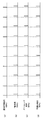
- the synchronization operation will be described with reference to FIG.
- the camera controller 140 transmits an exposure synchronization signal having a frequency of 60 (Hz) to the lens controller 240 (see FIG. 3A).
- the lens controller 240 acquires the F value in synchronization with the exposure synchronization signal (see FIG. 3B).
- the lens controller 240 can perform drive control of the diaphragm 260 according to the acquired F value.
- the lens controller 240 acquires position information of the zoom lens 210 in synchronization with the exposure synchronization signal (see FIG. 3C).
- the lens controller 240 detects a camera shake state in response to acquiring the exposure synchronization signal (see FIG. 3D).
- the lens controller 240 can perform drive control of the OIS lens 220 in accordance with the detected camera shake state.
- the lens controller 240 controls the diaphragm 260, the zoom lens 210, the OIS lens 220, and the like, while synchronizing with the exposure synchronization signal acquired by the lens controller 240 from the camera controller 140, and the same frequency as the exposure synchronization signal. It is performed at 60 (Hz).
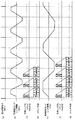
- the wobbling operation of the focus lens 230 is performed in synchronization with an exposure synchronization signal (see FIG. 5A) acquired from the camera body 100.
- the frequency of the wobbling operation of the focus lens 230 does not necessarily match the frequency of the exposure synchronization signal acquired from the camera body 100.
- the camera system 1 performs the following wobbling operation when the focus lens 230 is operated so that the camera body 100 and the interchangeable lens 200 can be synchronized even if the frequency of the exposure synchronization signal is different from the frequency of the wobbling operation. The operation is performed.
- the camera system 1 when the power of the camera system 1 is switched from OFF to ON, the camera system 1 performs an initialization operation.
- the interchangeable lens 200 In the initialization operation, the interchangeable lens 200 notifies the camera body 100 of information regarding the ratio of the frequency that can be handled with respect to the frequency of the acquired exposure synchronization signal and information about the frequency of the wobbling operation that can be handled (S30).
- the camera controller 140 waits until receiving a through image generation instruction or a moving image imaging instruction (S32). ).
- the camera controller 140 determines the wobbling frequency specified by the set following mode based on the information about the frequency of the corresponding wobbling operation acquired from the interchangeable lens 200. In step S33, it is determined whether the focus lens 230 can be wobbled.
- the camera controller 140 determines that the wobbling operation of the focus lens 230 cannot be performed at the wobbling frequency specified by the set following mode, the camera controller 140 displays on the liquid crystal monitor 120 that the set following mode cannot be supported ( S34).
- the camera controller 140 determines that the focus lens 230 can be wobbled at the wobbling frequency defined by the set tracking mode, the camera controller 140 relates to the frequency of the exposure synchronization signal transmitted from the camera controller 140 to the lens controller 240. Information and information regarding the frequency for causing the focus lens 230 to perform a wobbling operation are transmitted (S35). The lens controller 240 receives these pieces of information (S36).
- the camera controller 140 transmits a synchronization start command to the lens controller 240 (S37).
- the lens controller transmits a response to the synchronization start command to the camera controller (S38).
- the camera controller 140 starts transmitting an exposure synchronization signal at a frequency transmitted in advance to the lens controller 240 (S39).
- the lens controller 240 When the lens controller 240 receives an exposure synchronization signal from the camera controller 140 (S40), the lens controller 240 issues a control command for the focus lens 230 in synchronization with the received exposure synchronization signal, and performs drive control of the focus lens 230. (S41).
- This control command is a command for controlling the driving of the focus lens 230 so that the focus lens 230 is wobbled at a frequency specified by the camera controller 140.
- the lens controller 240 issues a control command as shown in FIG. 5C to control the wobbling operation of the focus lens 230.
- the control command shown in FIG. 5C controls the drive of the focus lens 230 in units of sections obtained by dividing one cycle (1/60 sec) of the synchronization signal into four sections. To do.
- the lens controller 240 issues a control command as shown in FIG. 5F to control the wobbling operation of the focus lens 230.
- the control command shown in FIG. 5F controls the drive of the focus lens 230 in units of sections obtained by dividing one cycle of the synchronization signal into four sections.
- the direction of the arrow described in the commands shown in FIGS. 5D and 5G indicates the driving direction of the focus lens 230 in each section. That is, an upward or downward arrow indicates movement of the focus lens 230 toward the near or far side with respect to the camera body, and a horizontal arrow indicates stop of the focus lens 230.
- the camera controller 140 transmits an exposure synchronization signal to the lens controller 240, and then determines whether or not to end the generation of the through image or the moving image capturing (S42).
- the release button 130 is fully pressed by the user to perform an image data recording operation, or the user ends the live view mode (through image generation). For example, when (end) is instructed.
- the camera controller 140 continues to transmit an exposure synchronization signal to the lens controller 240.
- the camera controller 140 stops transmitting the exposure synchronization signal to the lens controller 240 and performs the generation of the through image or the moving image capturing. The process ends (S42).
- the camera system 1 has a configuration in which the wobbling control of the focus lens 230 is performed at a frequency different from the frequency of the exposure synchronization signal while the exposure synchronization signal is generated at a constant frequency.
- the camera system 1 synchronizes various driving operations at the frequency of the exposure synchronization signal between the camera body 100 and the interchangeable lens 200, while wobbling the focus lens 230 at a frequency different from the frequency of the exposure synchronization signal.
- the operation can be controlled.
- the camera system 1 can cause the focus lens 230 to perform a wobbling operation at a frequency suitable for the wobbling operation, and can synchronize various drives with an exposure synchronizing signal having a constant frequency.
- the flash memory 242 can support wobbling operation with information on the wobbling operation drive cycle that can be supported and the frequency of the exposure synchronization signal to be acquired and in what ratio frequency. And the information regarding the drive cycle and the information regarding the ratio are transmitted to the camera body 100 at the initialization stage, and the camera controller 140 transmits the information regarding the drive cycle, the ratio information, and the exposure synchronization signal.
- the frequency for wobbling the focus lens 230 is determined from the above frequency.
- the camera body 100 can accurately control the interchangeable lens even when the interchangeable lens that can handle wobbling operations of different frequencies is attached.
- the information regarding the drive cycle of the corresponding wobbling operation stored in the flash memory 242 is the ratio between the drive cycle that can be followed during the wobbling operation and the cycle of the exposure synchronization signal. It is information which shows. As a result, regardless of the frequency of the exposure synchronization signal, a wobbling operation at a frequency different from the frequency of the exposure synchronization signal can be performed under a certain restriction of the ratio.
- the camera system of the present embodiment includes a camera body 100 and an interchangeable lens 200.
- the camera body 100 captures a subject image formed by the interchangeable lens 200 at a predetermined imaging cycle and generates image data as a moving image, and a cycle (first cycle) correlated with the imaging cycle.
- a body mount 150 that transmits the exposure synchronization signal to the interchangeable lens 200.
- the camera controller 140 further transmits information indicating a period (second period) different from the period (first period) of the exposure synchronization signal to the interchangeable lens 200 via the body mount 150.
- the interchangeable lens 200 includes a focus lens 230, a focus motor 233 that drives the focus lens 230 along the optical axis, and a lens mount 250 that receives an exposure synchronization signal and information indicating the second period transmitted from the camera controller 140. And a lens controller 240 for controlling the operation of the interchangeable lens.
- the lens controller 240 controls the focus motor 233 so that the focus lens 230 is minutely advanced and retracted along the optical axis in the second cycle, and performs control different from the minute advance and retract drive in the interchangeable lens in the first cycle. Do.
- the camera system 1 synchronizes various driving operations at the frequency of the exposure synchronization signal between the camera body 100 and the interchangeable lens 200, while wobbling the focus lens 230 at a frequency different from the frequency of the exposure synchronization signal.
- the operation can be controlled.
- the camera system 1 can control the wobbling operation of the focus lens 230 at a frequency suitable for wobbling.
- the interchangeable lens 200 may store in advance in the flash memory 242 period information relating to a driving period that can be followed during minute advance / retreat driving.
- the period information stored in the flash memory 242 may be transmitted to the camera body 100.
- the camera controller 140 may designate the second period with reference to the period information received from the body mount 150.
- the camera body 100 can accurately control the interchangeable lens even when the interchangeable lens that can handle wobbling operations of different frequencies is attached.
- the cycle information stored in the flash memory 242 may be information indicating a ratio between a drive cycle that can be followed during the minute advance / retreat drive and a cycle of the synchronization signal. .
- a wobbling operation at a frequency different from the frequency of the exposure synchronization signal can be performed under a certain restriction of the ratio.
- the frequency of the exposure synchronization signal is 60 Hz, but the frequency is not limited to this.
- the frequency of the exposure synchronization signal may be 30 Hz or 15 Hz, for example, and can be set to an arbitrary frequency.
- the interchangeable lens flash memory 242 In the camera system 1 of the first embodiment, in the interchangeable lens flash memory 242, information on the ratio of the wobbling frequency that can be controlled by the lens controller 240 to the frequency of the exposure synchronization signal and information on the wobbling frequency that can be controlled are stored. did.
- the present invention is not limited to this configuration, and the flash memory 242 may store information on the frequency of the exposure synchronizing signal that can be handled by the interchangeable lens and the ratio of the wobbling frequency that the interchangeable lens can handle to the frequency of the exposure synchronizing signal. Good.
- An example is shown in FIG. In FIG. 6, a control frequency support flag is shown as information indicating the control frequency and wobbling frequency that the interchangeable lens can support.
- Such a control frequency correspondence flag may be transmitted from the interchangeable lens 200 to the camera body 100 as lens data.
- the control frequency corresponding flag is composed of 15 bits, and each bit constitutes a flag.
- the first to twelfth bits are flags indicating whether or not the interchangeable lens 200 is compatible with the control frequency corresponding to each flag.
- Each flag indicates “corresponding” if the value is 1, and indicates “non-corresponding” if the value is 0.
- the interchangeable lens 200 can be driven at a control frequency of 60 Hz, and This means that the wobbling operation can be performed at half the frequency (30 Hz).
- the flash memory 242 may store information on the frequency of the exposure synchronization signal that can be handled by the interchangeable lens and the ratio of the wobbling frequency that can be handled by the interchangeable lens for each frequency. As a result, the combination of the frequency of the exposure synchronization signal that can be handled by the interchangeable lens and the wobbling frequency can be defined more precisely.
- the camera system 1 of the first embodiment has the low-speed tracking mode and the high-speed tracking mode as the tracking mode, but is not necessarily limited to such a configuration.
- the camera system 1 may have only the low-speed tracking mode, or may have only the high-speed tracking mode.
- a mode such as a medium speed tracking mode may be provided.
- the camera system 1 may have any following mode, and may have any number of following modes.
- the liquid crystal monitor 120 displays that the correspondence is impossible, but the present invention is not necessarily limited to such a configuration.
- the wobbling control of the focus lens 230 may be performed at a driving frequency that is closest to the driving frequency of the set tracking mode among the wobbling frequencies that can be handled.
- the camera controller 140 designates the frequency for wobbling the focus lens 230 to the lens controller 240, but the configuration is not necessarily limited thereto.
- the camera controller 140 may transmit a synchronization signal having a frequency equal to the wobbling frequency of the focus lens 230 to the lens controller 240.
- the section corresponding to one cycle of the exposure synchronization signal is divided into four sections to control the driving of the focus lens 230.
- the configuration is not necessarily limited to such a configuration.
- the drive of the focus lens 230 may be controlled by dividing one cycle into five sections, or the drive of the focus lens 230 may be controlled by dividing into eight sections.
- the driving of the focus lens 230 may be controlled in any number of sections.
- the wobbling operation is performed so that the moving locus of the lens becomes a trapezoidal wave.
- the configuration is not necessarily limited to this.
- a wobbling operation may be performed so that the movement locus of the lens becomes a triangular wave.
- any wobbling operation may be used as long as it is an operation that makes a slight advance and retreat along the optical axis of the focus lens 230.
- the configuration including the zoom lens 210 and the OIS lens 220 is illustrated, but these are not essential configurations.
- the idea of Embodiment 1 can be applied to a camera system equipped with a single focus lens that does not have a zoom function, and also to a camera system equipped with an interchangeable lens that does not have a camera shake correction function. Applicable.
- a camera body that does not include a movable mirror is illustrated, but the configuration of the camera body is not limited to this.
- a movable mirror may be provided in the camera body, or a prism for separating the subject image may be provided.
- the structure provided with a movable mirror not in a camera body but in an adapter may be sufficient.
- the CCD image sensor 110 is exemplified as the image sensor, but the image sensor is not limited to this.
- the image sensor may be constituted by, for example, a CMOS image sensor or an NMOS image sensor.
- the present invention can be applied to an interchangeable lens camera system. Specifically, it can be applied to a digital still camera or a movie.
Abstract
Description
1-1.構成
1-1-1.概要
図1は、実施の形態1のカメラシステムの構成を示すブロック図である。カメラシステム1は、カメラボディ100とそれに着脱可能な交換レンズ200とから構成される。カメラシステム1は、CCDイメージセンサ110で画像データを周期的に撮像することにより動画像データを生成することが可能である。本発明は、レンズ交換式のカメラシステムに関する発明である。特に、本発明は、スルー画像の生成や動画像撮像を行う際に、カメラボディと交換レンズとの同期を的確に取るためになされた発明である。
カメラボディ100は、CCDイメージセンサ110と液晶モニタ120とカメラコントローラ140とボディマウント150と電源160とカードスロット170とを備える。
交換レンズ200は、光学系とレンズコントローラ240とレンズマウント250とを備える。交換レンズ200の光学系は、ズームレンズ210、OISレンズ220、絞り260、フォーカスレンズ230を含む。
前述のように、本実施の形態のカメラシステム1において、レンズコントローラ240は、カメラコントローラ140から取得する露光同期信号の周波数と異なる周波数で、フォーカスレンズ230のウォブリング制御を行うことができる。そこで、本実施形態のフラッシュメモリ242は、レンズコントローラ240がフォーカスレンズ230をウォブリング動作させることが可能な周波数と、カメラコントローラ140から取得する露光同期信号の周波数との関係を示す情報を記憶する。これにより、ウォブリング動作を他の制御と独立した周波数で制御できる。
カメラコントローラ140はボディ側制御手段の一例である。ボディマウント150は送信手段の一例である。レンズマウント250は受信手段の一例である。レンズコントローラ240はレンズ制御手段の一例である。CCDイメージセンサ110は、撮像手段の一例である。フォーカスモータ233は駆動手段の一例である。フラッシュメモリ242は、記憶手段の一例である。
以上のように構成されたカメラシステムの動作を図2~4を用いて説明する。
カメラシステム1において、交換レンズ200は、カメラボディ100から受信した露光同期信号に同期して動作する同期モードと、露光同期信号に同期しない(すなわち、交換レンズ200内で生成したタイミングで動作する)非同期モードとを有する。交換レンズ200が同期モードで動作するか、非同期モードで動作するかは、カメラコントローラ140がカメラボディ100における制御状態に応じて決定する。
カメラコントローラ140は、非同期モードから同期モードへ移行すると、同期開始コマンドをレンズコントローラ240に対して発信する。レンズコントローラ240は、同期開始コマンドを受信すると、カメラコントローラ140から受信する露光同期信号に同期して制御動作を行う。具体的には、露光同期信号に同期して、フォーカスモータ233や絞りモータ261の駆動状態を把握し、その結果をカメラコントローラ140に送信する。
カメラコントローラ140は、同期モードから非同期モードへ移行すると、同期終了コマンドをレンズコントローラ240に対して発信する。レンズコントローラ240は、同期終了コマンドを受信すると、カメラコントローラ140から受信する露光同期信号には同期しないで制御動作を行う。
スルー画像生成時や動画像撮像時には、カメラコントローラ140は、使用者の操作により、マニュアルフォーカスモード、オートフォーカスモード、若しくは被写体追従モードの中からいずれかを選択可能である。さらに、カメラコントローラ140は、被写体追従モードが選択された場合、使用者の操作により、低速追従モードおよび高速追従モードの中からいずれかを選択可能である。本発明の実施の形態では、使用者が被写体追従モードを選択している場合について説明する。なお、ここでオートフォーカスモードとは、使用者によってレリーズ釦130が半押しされない限り、特に被写体像のフォーカス状態を変化させないモードである。
本実施の形態のカメラシステムにおいて、交換レンズ200は、カメラボディ100から取得する露光同期信号に同期して様々な動作を行う。例えば、交換レンズ200は、フォーカスレンズ230、絞り260、ズームレンズ210、OISレンズ220の駆動制御を露光同期信号に同期して行う。以下、同期動作について図3を用いて説明する。
同期期間中においてフォーカスレンズ230を駆動制御することにより実現されるウォブリング動作について図4、図5を用いて説明する。
本実施の形態のカメラシステムはカメラボディ100と交換レンズ200を含む。カメラボディ100は、交換レンズ200により形成された被写体像を所定の撮像周期で撮像して、動画像として画像データを生成できるCCDイメージセンサ110と、撮像周期と相関のある周期(第1の周期)で露光同期信号を生成するカメラコントローラ140と、露光同期信号を交換レンズ200に送信するボディマウント150とを備える。カメラコントローラ140は、さらに、露光同期信号の周期(第1の周期)と異なる周期(第2の周期)を示す情報を、ボディマウント150を介して、交換レンズ200に送信する。交換レンズ200は、フォーカスレンズ230と、フォーカスレンズ230を光軸に沿って駆動するフォーカスモータ233と、カメラコントローラ140から送信された露光同期信号及び第2の周期を示す情報を受信するレンズマウント250と、交換レンズの動作を制御するレンズコントローラ240とを備える。レンズコントローラ240は、第2の周期で、フォーカスレンズ230を光軸に沿って微小進退駆動させるようフォーカスモータ233を制御し、第1の周期で、交換レンズ内における微小進退駆動とは異なる制御を行う。
実施の形態1のカメラシステム1において、露光同期信号の周波数を60Hzとしたが、周波数はこれに限られない。露光同期信号の周波数は、例えば、30Hzまたは15Hzであってもよく、任意の周波数に設定できる。
110 CCDイメージセンサ
111 ADコンバーター
112 タイミング発生器
120 液晶モニタ
130 レリーズ釦
140 カメラコントローラ
141 DRAM
150 ボディマウント
160 電源
170 カードスロット
171 メモリーカード
200 交換レンズ
210 ズームレンズ
211 駆動機構
212 検出器
220 OISレンズ
221 アクチュエータ
222 位置検出センサ
223 OIS用IC
230 フォーカスレンズ
233 フォーカスモータ
240 レンズコントローラ
241 DRAM
242 フラッシュメモリ
243 カウンタ
250 レンズマウント
260 絞り
261 絞りモータ
Claims (9)
- カメラボディと交換レンズとを含むカメラシステムであって、
前記カメラボディは、
前記交換レンズにより形成された被写体像を所定の撮像周期で撮像し、画像データを生成する撮像手段と、
前記撮像周期と相関のある第1の周期を持つ同期信号を生成するボディ制御手段と、
前記生成された同期信号を前記交換レンズに送信する送信手段とを備え、
前記ボディ制御手段は、さらに、前記第1の周期と異なる第2の周期を示す情報を、前記送信手段を介して前記交換レンズに送信し、
前記交換レンズは、
フォーカスレンズと、
前記フォーカスレンズを光軸に沿って駆動する駆動手段と、
前記カメラボディから送信された同期信号及び第2の周期を示す情報を受信する受信手段と、
前記交換レンズの動作を制御するレンズ制御手段と、を備え、
前記レンズ制御手段は、前記第2の周期で、前記フォーカスレンズを光軸に沿って微小進退駆動させるよう前記駆動手段を制御し、前記第1の周期で、前記交換レンズ内における前記微小進退駆動とは異なる制御を行う、
カメラシステム。 - 前記交換レンズは、前記交換レンズが対応可能な前記微小進退駆動の駆動周期に関する周期情報を予め記憶する記憶手段をさらに備え、
前記ボディ制御手段は、前記交換レンズから前記周期情報を受信し、その受信した周期情報を参照して前記第2の周期を設定する、
請求項1に記載のカメラシステム。 - 前記周期情報は、前記同期信号の周期に対する前記微小進退駆動の際に対応可能な駆動周期の比率を示す情報である、
請求項2に記載のカメラシステム。 - 前記比率は、1/2、1/4、1/8の少なくともいずれかである、請求項3に記載のカメラシステム。
- カメラボディと交換レンズとを含むカメラシステムであって、
前記カメラボディは、
前記交換レンズにより形成された被写体像を所定の撮像周期で撮像し、画像データを生成する撮像手段と、
前記撮像周期と相関のある第1の周期を持つ第1の同期信号を生成するボディ制御手段と、
前記生成された同期信号を前記交換レンズに送信する送信手段とを備え、
前記ボディ制御手段は、さらに、第2の周期を持つ第2の同期信号を生成して前記交換レンズに送信し、
前記交換レンズは、
フォーカスレンズと、
前記フォーカスレンズを光軸に沿って駆動する駆動手段と、
前記カメラボディから送信された第1及び第2の同期信号を受信する受信手段と、
前記交換レンズの動作を制御するレンズ制御手段と、を備え、
前記レンズ制御手段は、前記第2の同期信号に従って、前記フォーカスレンズの位置を前記光軸に沿って微小進退駆動させるよう前記駆動手段を制御し、前記第1の周期で、前記交換レンズ内における前記微小進退駆動とは異なる制御を行う、
カメラシステム。 - 交換レンズが装着可能なカメラボディであって、
前記交換レンズにより形成された被写体像を所定の撮像周期で撮像し、画像データを生成する撮像手段と、
前記撮像周期と相関のある第1の周期を持つ同期信号を生成するボディ制御手段と、
前記生成された同期信号を前記交換レンズに送信する送信手段とを備え、
前記ボディ制御手段は、さらに、前記フォーカスレンズを光軸に沿って微小進退駆動させるための周期であって前記第1の周期と異なる第2の周期を示す情報を、前記送信手段を介して前記交換レンズに送信する、
カメラボディ。 - 前記ボディ制御手段は、前記交換レンズから、前記交換レンズが対応可能な前記微小進退駆動の駆動周期に関する周期情報を受信し、その受信した周期情報を参照して前記第2の周期を設定する、
請求項6記載のカメラボディ。 - カメラボディに装着可能な交換レンズであって、
フォーカスレンズと、
前記フォーカスレンズを光軸に沿って駆動する駆動手段と、
前記カメラボディから送信された第1の周期を有する同期信号及び前記第1の周期と異なる第2の周期を示す情報を受信する受信手段と、
前記交換レンズの動作を制御するレンズ制御手段と、を備え、
前記レンズ制御手段は、前記第2の周期で、前記フォーカスレンズを光軸に沿って微小進退駆動させるよう前記駆動手段を制御し、前記第1の周期で、前記交換レンズ内における前記微小進退駆動とは異なる制御を行う、
交換レンズ。 - 前記交換レンズは、前記交換レンズが対応可能な前記微小進退駆動の駆動周期に関する周期情報を予め記憶する記憶手段をさらに備える、
請求項8に記載の交換レンズ。
Priority Applications (4)
| Application Number | Priority Date | Filing Date | Title |
|---|---|---|---|
| US12/992,790 US8570428B2 (en) | 2008-05-16 | 2009-05-15 | Camera system having autofocus function for capturing a moving image |
| JP2009537340A JP4426644B2 (ja) | 2008-05-16 | 2009-05-15 | カメラシステム |
| EP09746393.9A EP2290948B1 (en) | 2008-05-16 | 2009-05-15 | Camera system |
| CN200980117566.XA CN102027737B (zh) | 2008-05-16 | 2009-05-15 | 照相机系统 |
Applications Claiming Priority (4)
| Application Number | Priority Date | Filing Date | Title |
|---|---|---|---|
| US5381508P | 2008-05-16 | 2008-05-16 | |
| US61/053,815 | 2008-05-16 | ||
| JP2008141928 | 2008-05-30 | ||
| JP2008-141928 | 2008-05-30 |
Publications (1)
| Publication Number | Publication Date |
|---|---|
| WO2009139186A1 true WO2009139186A1 (ja) | 2009-11-19 |
Family
ID=41318560
Family Applications (1)
| Application Number | Title | Priority Date | Filing Date |
|---|---|---|---|
| PCT/JP2009/002151 WO2009139186A1 (ja) | 2008-05-16 | 2009-05-15 | カメラシステム |
Country Status (4)
| Country | Link |
|---|---|
| US (1) | US8570428B2 (ja) |
| EP (1) | EP2290948B1 (ja) |
| JP (2) | JP4426644B2 (ja) |
| WO (1) | WO2009139186A1 (ja) |
Cited By (4)
| Publication number | Priority date | Publication date | Assignee | Title |
|---|---|---|---|---|
| WO2011070215A1 (en) * | 2009-12-07 | 2011-06-16 | Nokia Corporation | An apparatus, a method, and a computer program product for automatic focusing |
| JP2011180262A (ja) * | 2010-02-26 | 2011-09-15 | Olympus Imaging Corp | フォーカス制御装置 |
| US20110317061A1 (en) * | 2010-06-29 | 2011-12-29 | Nikon Corporation | Interchangeable lens, camera body and camera system |
| JP2012237932A (ja) * | 2011-05-13 | 2012-12-06 | Nikon Corp | 交換レンズおよびカメラボディ |
Families Citing this family (14)
| Publication number | Priority date | Publication date | Assignee | Title |
|---|---|---|---|---|
| US8095000B2 (en) * | 2007-02-15 | 2012-01-10 | Panasonic Corporation | Camera system |
| JP4880756B2 (ja) * | 2007-07-31 | 2012-02-22 | パナソニック株式会社 | カメラシステムおよびカメラ本体 |
| US8767119B2 (en) * | 2009-03-13 | 2014-07-01 | Panasonic Corporation | Interchangeable lens, camera body, and camera system |
| EP2713206B1 (en) * | 2011-06-29 | 2016-04-20 | Olympus Corporation | Camera device, replacement lens device, camera main body, and focus control method |
| JP6012973B2 (ja) | 2012-02-06 | 2016-10-25 | オリンパス株式会社 | 焦点調節装置およびカメラシステムならびに焦点調節方法 |
| JP5891840B2 (ja) * | 2012-02-23 | 2016-03-23 | 株式会社ニコン | 撮影装置 |
| JP5963526B2 (ja) | 2012-04-27 | 2016-08-03 | キヤノン株式会社 | レンズ装置及びそれを有する撮像装置 |
| JP5832373B2 (ja) * | 2012-05-16 | 2015-12-16 | キヤノン株式会社 | 交換レンズ装置およびカメラ装置 |
| JP5917288B2 (ja) * | 2012-05-18 | 2016-05-11 | キヤノン株式会社 | 撮像装置、レンズ装置および撮像システム |
| JP5627652B2 (ja) * | 2012-06-06 | 2014-11-19 | キヤノン株式会社 | 撮像装置およびその制御方法、並びにレンズ装置およびその制御方法 |
| CN108369326B (zh) | 2015-12-22 | 2019-07-09 | 富士胶片株式会社 | 摄像装置、对焦控制方法及对焦控制程序 |
| JP6851726B2 (ja) | 2016-04-04 | 2021-03-31 | キヤノン株式会社 | 制御装置、撮像装置、制御方法、プログラム、および、記憶媒体 |
| CN108803200B (zh) * | 2018-06-29 | 2021-03-09 | 歌尔光学科技有限公司 | 滤光片切换系统 |
| EP4057061A4 (en) * | 2019-12-16 | 2022-12-28 | Sony Group Corporation | PHOTOGRAPHY SYSTEM, CONTROL METHOD AND PROGRAM |
Citations (5)
| Publication number | Priority date | Publication date | Assignee | Title |
|---|---|---|---|---|
| US5381508A (en) | 1993-08-25 | 1995-01-10 | Krumenacher; Paul F. | Suction and light guide assembly |
| JPH11155094A (ja) * | 1997-11-19 | 1999-06-08 | Ricoh Co Ltd | オートフォーカス装置 |
| JP2007322922A (ja) | 2006-06-02 | 2007-12-13 | Olympus Imaging Corp | 撮像システム及びカメラ並びにレンズユニット |
| JP2008015274A (ja) * | 2006-07-06 | 2008-01-24 | Olympus Imaging Corp | デジタルカメラ |
| JP2008141928A (ja) | 2006-12-05 | 2008-06-19 | Tamagawa Seiki Co Ltd | 断線検出システム |
Family Cites Families (21)
| Publication number | Priority date | Publication date | Assignee | Title |
|---|---|---|---|---|
| US4783677A (en) * | 1986-06-21 | 1988-11-08 | Minolta Camera Kabushiki Kaisha | Automatic focus control device |
| EP0679918B1 (en) * | 1989-02-09 | 2003-01-15 | Canon Kabushiki Kaisha | Camera apparatus |
| EP0424678B1 (en) | 1989-09-27 | 1996-09-04 | Canon Kabushiki Kaisha | Camera system controlling interchangeable lenses |
| JPH05236326A (ja) * | 1991-03-05 | 1993-09-10 | Konica Corp | 自動焦点調節装置 |
| US5648836A (en) * | 1993-02-18 | 1997-07-15 | Canon Kabushiki Kaisha | Optical apparatus with control device for controlling movable optical member |
| JPH08129199A (ja) | 1994-09-07 | 1996-05-21 | Nikon Corp | カメラボディ、カメラアクセサリおよびカメラシステム |
| US6445416B1 (en) * | 1995-06-30 | 2002-09-03 | Canon Kabushiki Kaisha | Image pickup apparatus having electronic zoom function based on optical zooming focal length variation with time |
| JP4149528B2 (ja) | 1996-01-17 | 2008-09-10 | オリンパス株式会社 | 自動焦点検出装置 |
| JPH1010405A (ja) | 1996-06-19 | 1998-01-16 | Canon Inc | レンズ装置及び撮像装置 |
| JPH1152220A (ja) | 1997-07-31 | 1999-02-26 | Sony Corp | オートフオーカス制御方法 |
| JP4020527B2 (ja) * | 1999-03-16 | 2007-12-12 | オリンパス株式会社 | 電子カメラ |
| JP4029296B2 (ja) | 2004-03-02 | 2008-01-09 | ソニー株式会社 | オートフォーカス制御装置および方法、記録媒体、並びにプログラム |
| JP4732748B2 (ja) * | 2004-07-02 | 2011-07-27 | ソニー株式会社 | 電子式カメラ及び自動フォーカス方法 |
| JP2006065176A (ja) | 2004-08-30 | 2006-03-09 | Canon Inc | 撮影装置 |
| JP4630649B2 (ja) * | 2004-11-24 | 2011-02-09 | キヤノン株式会社 | カメラ |
| JP4933049B2 (ja) | 2005-01-31 | 2012-05-16 | キヤノン株式会社 | レンズシステムおよびカメラシステム |
| JP2007104364A (ja) * | 2005-10-05 | 2007-04-19 | Fujifilm Corp | カメラシステム及びデジタルカメラ |
| JP2007171506A (ja) * | 2005-12-21 | 2007-07-05 | Fujifilm Corp | カメラシステム |
| US7725018B2 (en) * | 2006-08-01 | 2010-05-25 | Canon Kabushiki Kaisha | Focus control apparatus, image sensing apparatus and focus control method |
| US8095000B2 (en) | 2007-02-15 | 2012-01-10 | Panasonic Corporation | Camera system |
| JP2009258558A (ja) | 2008-04-21 | 2009-11-05 | Canon Inc | 選択された撮影モードに応じて通信方式を切り換えるレンズ交換式カメラ本体、交換レンズ及びカメラシステム |
-
2009
- 2009-05-15 WO PCT/JP2009/002151 patent/WO2009139186A1/ja active Application Filing
- 2009-05-15 JP JP2009537340A patent/JP4426644B2/ja active Active
- 2009-05-15 EP EP09746393.9A patent/EP2290948B1/en active Active
- 2009-05-15 US US12/992,790 patent/US8570428B2/en active Active
- 2009-12-10 JP JP2009280033A patent/JP2010063162A/ja active Pending
Patent Citations (5)
| Publication number | Priority date | Publication date | Assignee | Title |
|---|---|---|---|---|
| US5381508A (en) | 1993-08-25 | 1995-01-10 | Krumenacher; Paul F. | Suction and light guide assembly |
| JPH11155094A (ja) * | 1997-11-19 | 1999-06-08 | Ricoh Co Ltd | オートフォーカス装置 |
| JP2007322922A (ja) | 2006-06-02 | 2007-12-13 | Olympus Imaging Corp | 撮像システム及びカメラ並びにレンズユニット |
| JP2008015274A (ja) * | 2006-07-06 | 2008-01-24 | Olympus Imaging Corp | デジタルカメラ |
| JP2008141928A (ja) | 2006-12-05 | 2008-06-19 | Tamagawa Seiki Co Ltd | 断線検出システム |
Non-Patent Citations (1)
| Title |
|---|
| See also references of EP2290948A4 |
Cited By (7)
| Publication number | Priority date | Publication date | Assignee | Title |
|---|---|---|---|---|
| WO2011070215A1 (en) * | 2009-12-07 | 2011-06-16 | Nokia Corporation | An apparatus, a method, and a computer program product for automatic focusing |
| US9167143B2 (en) | 2009-12-07 | 2015-10-20 | Nokia Technologies Oy | Apparatus, a method, and a computer program for automatic focusing |
| JP2011180262A (ja) * | 2010-02-26 | 2011-09-15 | Olympus Imaging Corp | フォーカス制御装置 |
| US20110317061A1 (en) * | 2010-06-29 | 2011-12-29 | Nikon Corporation | Interchangeable lens, camera body and camera system |
| CN102314051A (zh) * | 2010-06-29 | 2012-01-11 | 株式会社尼康 | 可换透镜、相机主体及相机系统 |
| US9036076B2 (en) * | 2010-06-29 | 2015-05-19 | Nikon Corporation | Interchangeable lens, camera body and camera system for transmitting drive condition information at different frequencies |
| JP2012237932A (ja) * | 2011-05-13 | 2012-12-06 | Nikon Corp | 交換レンズおよびカメラボディ |
Also Published As
| Publication number | Publication date |
|---|---|
| US8570428B2 (en) | 2013-10-29 |
| JP4426644B2 (ja) | 2010-03-03 |
| JP2010063162A (ja) | 2010-03-18 |
| US20110063472A1 (en) | 2011-03-17 |
| JPWO2009139186A1 (ja) | 2011-09-15 |
| EP2290948A1 (en) | 2011-03-02 |
| EP2290948A4 (en) | 2011-11-09 |
| EP2290948B1 (en) | 2020-01-22 |
Similar Documents
| Publication | Publication Date | Title |
|---|---|---|
| JP4426644B2 (ja) | カメラシステム | |
| WO2009139118A1 (ja) | カメラシステム | |
| US8724012B2 (en) | Camera body and camera system using driving method information indicating capability of controlling focus lens | |
| JP5520214B2 (ja) | カメラシステム | |
| JP6706819B2 (ja) | ズーム機構を備えた撮像装置及び交換レンズ | |
| US8432480B2 (en) | Interchangeable lens, camera body and camera system | |
| JP5406830B2 (ja) | カメラシステム | |
| JP5535080B2 (ja) | カメラシステム | |
| US8126322B2 (en) | Interchangeable lens, camera body, and camera system | |
| JP5853197B2 (ja) | 交換レンズ、カメラボディ及びカメラシステム | |
| JP5495617B2 (ja) | 交換レンズ、カメラボディ、及びカメラシステム | |
| WO2009128263A1 (ja) | 交換レンズ、カメラボディ、カメラシステム | |
| JP2009258718A (ja) | カメラシステム並びにカメラボディ及び交換レンズ | |
| JP2008276131A (ja) | カメラシステム | |
| WO2009139193A1 (ja) | カメラシステム | |
| JP5062026B2 (ja) | カメラ本体、交換レンズ | |
| JP2010026502A (ja) | 撮像装置及びカメラシステム | |
| JP2010107714A (ja) | カメラシステム | |
| JP2013228623A (ja) | 撮像装置、レンズユニット及び通信制御方法 | |
| JP2009246701A (ja) | 録音装置 |
Legal Events
| Date | Code | Title | Description |
|---|---|---|---|
| WWE | Wipo information: entry into national phase |
Ref document number: 200980117566.X Country of ref document: CN |
|
| WWE | Wipo information: entry into national phase |
Ref document number: 2009537340 Country of ref document: JP |
|
| 121 | Ep: the epo has been informed by wipo that ep was designated in this application |
Ref document number: 09746393 Country of ref document: EP Kind code of ref document: A1 |
|
| WWE | Wipo information: entry into national phase |
Ref document number: 12992790 Country of ref document: US |
|
| NENP | Non-entry into the national phase |
Ref country code: DE |
|
| WWE | Wipo information: entry into national phase |
Ref document number: 2009746393 Country of ref document: EP |