WO2009131185A1 - 粘性・弾性測定装置および粘性・弾性測定方法 - Google Patents
粘性・弾性測定装置および粘性・弾性測定方法 Download PDFInfo
- Publication number
- WO2009131185A1 WO2009131185A1 PCT/JP2009/058089 JP2009058089W WO2009131185A1 WO 2009131185 A1 WO2009131185 A1 WO 2009131185A1 JP 2009058089 W JP2009058089 W JP 2009058089W WO 2009131185 A1 WO2009131185 A1 WO 2009131185A1
- Authority
- WO
- WIPO (PCT)
- Prior art keywords
- rotor
- viscosity
- elasticity
- sample
- rotation
- Prior art date
- Legal status (The legal status is an assumption and is not a legal conclusion. Google has not performed a legal analysis and makes no representation as to the accuracy of the status listed.)
- Ceased
Links
Images

Classifications
-
- G—PHYSICS
- G01—MEASURING; TESTING
- G01N—INVESTIGATING OR ANALYSING MATERIALS BY DETERMINING THEIR CHEMICAL OR PHYSICAL PROPERTIES
- G01N11/00—Investigating flow properties of materials, e.g. viscosity, plasticity; Analysing materials by determining flow properties
- G01N11/10—Investigating flow properties of materials, e.g. viscosity, plasticity; Analysing materials by determining flow properties by moving a body within the material
- G01N11/14—Investigating flow properties of materials, e.g. viscosity, plasticity; Analysing materials by determining flow properties by moving a body within the material by using rotary bodies, e.g. vane
- G01N2011/147—Magnetic coupling
Definitions
- the present invention relates to a viscosity / elasticity measuring apparatus and a viscosity / elasticity measuring method for measuring viscosity and elasticity which are mechanical properties of a substance.
- Viscosity and elasticity of substances are measured in the manufacturing process of pharmaceuticals, foods, paints, inks, cosmetics, chemical products, paper, adhesives, fibers, plastics, beverages (eg beer), detergents, concrete admixtures, silicon, etc. It is an indispensable measurement technology for management, performance evaluation, raw material management, and research and development. Therefore, conventionally, measurement of viscosity and elasticity has been performed in order to detect the mechanical properties of the target substance (see, for example, Patent Document 1).
- Conventionally known methods for measuring viscosity include the following methods. (1) In the viscosity tube method, the viscosity of the fluid is measured from the speed at which the fluid flows through the narrow tube. (2) A method in which a vibrator is brought into contact with a sample and viscosity is measured by a change in amplitude. (3) A method for measuring viscosity from the propagation characteristics of surface acoustic waves. (4) A method of measuring viscosity by directly measuring a torque generated by viscous resistance by rotating a rotor in a sample. (5) A method of measuring the viscosity from the falling time of the hard sphere falling in the fluid sample.
- viscosity is obtained from a diffusion coefficient obtained by irradiating a laser beam to a Brownian moving particle and measuring dynamic scattering.
- a probe suspended in a sample is rotated, and the viscosity is measured from the rotational torque.
- the methods described in (1) to (5) have a drawback that a large amount of sample of several cc or more is required for measuring viscosity.
- the sample needs to have a viscosity of at least 10 cP in order to accurately measure the viscosity. Therefore, these methods have a drawback that the viscosity of a low-viscosity material cannot be measured.
- the method (6) has a drawback that the measuring apparatus becomes large, and there is a difficulty that it cannot be applied to other than the transparent sample.
- the method described in (7) has a disadvantage that the probe floated on the surface by buoyancy is rotated, causing ripples on the sample surface, and energy loss for this cannot be ignored. Further, when a molecular adsorption film is formed on the surface of the sample, there is a drawback that a measurement error occurs due to the surface viscoelasticity of the film. Since the rotation of the probe depends on the length of the portion submerged in the fluid sample, there is a restriction that the density of the sample material needs to be known. In any of the methods described in (1) to (7), the sample container is expensive and the container needs to be reused. For this reason, it is necessary to clean the sample container after the measurement. If the previous measurement sample is not completely removed, the influence remains and there is a restriction that high-precision measurement cannot be performed.
- the viscoelasticity measuring methods generally used until now have a drawback that a certain amount of sample is required in order to obtain a certain measurement accuracy.
- measurement accuracy is deteriorated for a substance having a viscosity of less than 100 cP.
- the rotational viscometer and the measurement by light scattering have a restriction that the apparatus becomes large and simple measurement cannot be performed.
- there were restrictions on measurement efficiency such as the need to clean the measurement container.
- the present invention has been made in view of such circumstances. Compared to conventional measurement methods, the present invention can measure viscosity and elasticity with a relatively small amount of sample, is a small and simple measuring device, and detects a substance to be detected. It is an object of the present invention to provide a viscosity / elasticity measuring apparatus and a viscosity / elasticity measuring method that can be disposed of at low cost.
- the viscosity / elasticity measuring apparatus stores a conductive rotor, a sample (a detection symmetric material for detecting viscosity and / or elasticity) and the rotor, and the sample is contained in the sample.
- a rotation control unit that induces an induced current and applies a rotational torque to the rotor to rotate by Lorentz interaction between the induced current and a magnetic field applied to the rotor, and detects a rotational motion of the rotor
- Viscosity / elasticity comprising: a rotation detection unit; and a dynamic characteristic detection unit (viscosity / elasticity detection unit) for detecting the viscosity / elasticity of the sample in contact with the rotor based on the rotational torque and the rotational motion It is a measuring device.
- the viscosity detected in the above apparatus may be indicated by the viscosity coefficient of the sample.
- the elasticity detected in the device may be indicated by an elastic modulus.
- the rotation detection unit detects the rotation number of the rotor
- the mechanical property detection unit detects the viscosity of the sample based on the rotation torque and rotation number of the rotor.
- -It may be an elasticity measuring device.
- the rotation detection unit is configured to move from an initial stationary position before the rotational torque is applied to an equilibrium stationary position where the rotor is stationary due to a balance between the rotational torque and the elastic resistance of the sample. It may be a viscosity / elasticity measuring device that detects a rotation angle and detects the elasticity of the sample based on the rotation torque and rotation angle of the rotor.
- the viscosity / elasticity measuring apparatus further includes a storage unit for storing standard data obtained by measuring in advance a relationship between the rotational torque of the rotor and the rotational speed in a plurality of substances (standard samples) having a known viscosity.
- a viscosity / elasticity measuring device that detects the viscosity of the sample by comparing the standard data with the relationship between the rotational torque and the rotational speed of the rotor in the sample measured by the mechanical property detection unit. There may be.
- the viscosity / elasticity measuring apparatus further includes a storage unit for storing standard data in which a relationship between a rotational torque and a rotational angle of the rotor in a plurality of substances having known elasticity is measured in advance, and the mechanical characteristics It may be a viscosity / elasticity measuring device that detects the elasticity of the sample by comparing the relationship between the rotation torque and the rotation angle of the rotor in the sample measured by the detection unit and the standard data. .
- the viscosity / elasticity measuring apparatus is a viscosity / elasticity measuring apparatus in which a mark is added to the rotor, and the rotation detecting unit detects the rotation of the rotor by detecting the rotation of the mark. Also good.
- the viscosity / elasticity measuring device at least a part of the bottom of the rotor is in contact with the bottom of the inner surface of the container, and the bottom of the inner surface of the container in contact with the rotor is a smooth flat surface or a smooth concave curved surface.
- the viscosity / elasticity measuring apparatus may be characterized in that the bottom of the rotor is a smooth convex curved surface.
- the viscosity / elasticity measuring device may be a viscosity / elasticity measuring device in which the radius of the rotor is determined by the following equation.
- R is the radius of the rotor
- g is the acceleration of gravity
- ⁇ is the angular velocity
- ⁇ is the viscosity coefficient
- ⁇ is the density difference between the rotor and the sample
- ⁇ is the friction coefficient between the lower part of the rotor and the bottom of the container
- ⁇ and ⁇ are It is a coefficient.
- the viscosity coefficient ⁇ may be a condition of R by applying a viscosity coefficient of a substance having a known viscosity similar to the sample (for example, a substance having substantially the same or chemical composition as the sample). .
- a value slightly higher than the viscosity coefficient of a substance having a known viscosity similar to the sample (about 110 to 150%) may be set as a temporary viscosity coefficient, and R may be obtained by applying the
- the viscosity / elasticity measuring apparatus may be a viscosity / elasticity measuring apparatus in which the rotor is partially or entirely submerged in the sample.
- the viscosity / elasticity measuring apparatus may be a viscosity / elasticity measuring apparatus in which the sample is a liquid or a soft material.
- the process of filling a container with a sample (substance to be detected) whose viscosity / elasticity is to be detected, placing a conductive rotor in the sample, and surrounding the container A process of applying a magnetic field to the rotor by an arranged magnet, and temporally changing the magnetic field, inducing an induced current in the rotor, and applying the induced current to the rotor Based on Lorentz interaction with a magnetic field, a rotation control process for applying rotation torque to the rotor for rotation, a rotation detection process for detecting the rotation movement of the rotor, the rotation torque and the rotation movement, and the rotor And a mechanical property detection process for detecting the viscosity and elasticity of a sample in contact with the sample.
- the viscosity detected in the above method may be indicated by the viscosity coefficient of the sample.
- the elasticity detected in the above method may be indicated by an elastic modulus.
- the viscosity / elasticity measuring method includes rotating the rotor in the rotation control process, detecting the rotation speed of the rotor in the rotation detection process, and determining the viscosity of the sample based on the rotation torque and the rotation speed. Viscosity / elasticity measuring method may be used.
- the viscosity / elasticity measuring method is an equilibrium stationary position where the rotor is stationary by the balance between elastic resistance and the torque from the initial stationary position before the torque is applied by the rotational torque.
- the rotor is rotated until the rotation angle from the initial stationary position to the equilibrium stationary position is detected in the rotation detection process, and in the mechanical characteristic detection process, the rotor is moved based on the rotation torque and the rotation angle. It may be a viscosity / elasticity measuring method for detecting the elasticity of the sample in contact.
- the viscosity / elasticity measuring method further includes a step of preparing standard data by measuring in advance the relationship between the rotational torque of the rotor and the rotational speed in a plurality of substances (standard samples) having a known viscosity.
- the viscosity / elasticity measuring method for detecting the viscosity of the sample by comparing the relation between the rotational torque of the rotor and the number of rotations in the sample with the standard data.
- the viscosity / elasticity measuring method further includes a step of preparing standard data by measuring in advance the relationship between the rotational torque and rotational angle of the rotor in a plurality of substances (standard samples) having known elasticity.
- the viscosity / elasticity measuring method for detecting the elasticity of the sample by comparing the relationship between the rotational torque and the rotation angle of the rotor in the sample with the standard data may be used.
- the magnetic field may be controlled to be a rotating magnetic field in which the horizontal direction of the magnetic field (the horizontal component of the magnetic field direction) rotates with time.
- the rotor may be made of a material having a specific gravity greater than that of the sample.
- the viscosity and / or elasticity is measured from the relationship between the rotational torque applied to the rotor rotating in contact with the sample and the rotational motion of the rotor, a small amount of detection object is detected.
- the rotor is rotated by applying a rotating magnetic field to the rotor, the rotation speed of the rotor is measured, the viscosity of the sample is detected from the relationship between the rotation torque and the rotation speed of the rotor, and the rotation torque and the rotor are detected.
- the container which puts a sample can utilize a normal test tube etc., and can be made disposable. Therefore, the labor for washing the container is omitted, and the influence of the immediately preceding measurement substance can be completely eliminated, and highly accurate measurement can be performed.
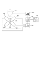
- FIG. 1 is a block diagram showing a configuration example of a viscosity / elasticity measuring apparatus according to the embodiment.
- a container 101 is, for example, a small test tube.
- the container 101 stores a detection target object for measuring viscosity (that is, viscosity coefficient) as a mechanical physical property.
- the inner diameter of the container 101 only needs to be slightly larger than the diameter of the rotor 106 described below. Further, the depth of the sample (detection target) stored in the container 101 at the time of measurement may be such that the rotor 106 is immersed.
- the rotor 106 may be partially or entirely submerged in the sample that is the detection target substance.
- the rotor 106 is made of a conductor (for example, a metal such as aluminum), and has a shape in which a lower portion in contact with the container 101 has a smooth convex curved surface.
- the rotor 106 may be spherical or hemispherical (that is, a shape in which a portion in contact with the inner bottom portion of the container 101 (the bottom portion of the container inner surface) has a shape of a part of a spherical surface).
- the rotor 106 may have a spheroid shape.
- the rotor 106 is disposed in the container 101 so as to be in contact with the detection target.
- the rotor 106 is arranged so that part or all of the rotor 106 is immersed in this detection target.
- the inner bottom portion of the container 101 with which the lower portion of the rotor 106 is in contact may be a smooth flat surface or may have a concave smooth curved surface.
- a commercially available metal sphere can be used as the rotor 106. Therefore, by using it together with a commercially available test tube of the container 101, the portion in contact with the sample can be made a disposable configuration. For this reason, there is an advantage that post-treatment such as incineration and sterilization can be easily performed even when a substance that requires special attention for disposal, such as biomaterials, is used as a measurement target.
- the rotor may be a metal sphere having a diameter of 1 cm or less or a diameter of 2 mm or less.
- viscosity and elasticity can be measured even with a sample having a volume of about 100 to 500 ⁇ l.
- electromagnets 102, 103, 104, and 105 are arranged.
- the set A of the electromagnet 102 and the electromagnet 103 is placed in series in the plane perpendicular to the longitudinal direction of the container 101 with the container 101 interposed therebetween.
- the set B of the electromagnet 104 and the electromagnet 105 is placed in series in the same plane as the set B with the container 101 interposed therebetween in a direction orthogonal to the arrangement direction of the set A. That is, when the longitudinal direction of the container 101 is arranged along the z axis of the orthogonal coordinate system, the set A can be arranged along the x axis and the set B can be arranged along the y axis.
- the tension direction of the container 106 may be arranged along the vertical direction, and the electromagnet sets A and B may be arranged in a horizontal plane.
- the electromagnets 102, 103, 104, and 105 are connected to the rotation control unit 107.
- the rotation control unit 107 alternately drives the electromagnets of the set A and the set B, and alternately generates and varies magnetic fields in two directions (x-axis direction and y-axis direction) orthogonal to each other. For example, when the rotation control unit 107 is driving the electromagnet 102 and the electromagnet 103 of the set A (that is, when a current is passed through the coils of the electromagnet 102 and the electromagnet 103), the electromagnet 104 and the electromagnet of the set B 105 is not driven.
- the rotation control unit 107 applies a rotating magnetic field to the rotor 106 by the electromagnet control described above, and induces an induced current in the rotor 106. Then, due to the Lorentz interaction between this induced current and the magnetic field applied to the rotor 106, the rotor 106 is rotated by giving a rotational torque.
- the dynamic characteristic detection unit 108 instructs the rotation control unit 107 about the time period for alternately driving.
- an electromagnet is used, and a rotating magnetic field is applied to the rotor 106 by driving the electromagnet coil by passing a current sequentially.
- a pair of permanent magnets are arranged in series via the container 101, and the permanent magnets are rotated around the container 101 by a motor or the like to apply a rotating magnetic field to the rotor 106.
- the rotor 106 may be configured to be given rotational torque.
- the rotation control unit 107 controls the rotation speed of the set of permanent magnets in response to an instruction from the mechanical characteristic detection unit 108.
- the image processing unit 109 includes, for example, an image sensor (CCD) having a microscope.
- the image processing unit 109 is disposed at the upper part of the opening of the container 101.
- the image processing unit 109 measures the rotation speed of the rotor 106 by detecting the rotation of the mark added to the rotor 106. Therefore, the image processing unit 109 is arranged above the container 101 so that the imaging direction is a position where a mark added to the upper surface of the rotor 106 can be detected.
- the standard data storage unit 110 stores standard data indicating the relationship between the rotational torque applied to the rotor 106 and the rotational speed of the rotor 106 for a plurality of standard samples having different viscosities.
- Standard data can be obtained by putting each standard sample in the container 101 in advance, rotating the rotor 106, and recording the rotational torque applied to the rotor 106 and the rotational speed of the rotor 106. In the measurement of each standard sample, the rotational speed at the rotor 106 is changed, the rotational torque at each rotational speed is calculated, and the slope of the linear curve approximated by the equation (8) described later is obtained as a standard. Set as part of the data.
- the mechanical property detection unit 108 is connected to the image processing unit 109 and the standard data storage unit.
- the dynamic characteristic detection unit 108 acquires data on the rotation speed of the rotor 106 output from the image processing unit 109 and the rotation torque corresponding to the rotation speed.
- the slope of the linear curve represented by the equation (8) described later is obtained for the detection target substance, and the ratio with the slope of the standard data read from the standard data storage unit 110 is obtained. That is, the slope of the primary curve of the standard data is divided by the slope of the primary curve of the detection target substance, and the viscosity ⁇ of the detection target substance is calculated by multiplying the slope of the standard data by the slope ratio.
- the mechanical property detection unit 108 can also determine the viscosity of the detection target substance based on a plurality of standard data.
- the mechanical property detection unit 108 may read the slopes of the primary curves in a plurality of different standard samples stored in the standard data storage unit 110.
- the slope of the primary curve of the standard data is divided by the slope of the primary curve of the substance to be detected, and the viscosity ratio is obtained by multiplying the viscosity of the corresponding standard data by the slope ratio.
- the viscosity value obtained based on the standard data may be averaged to obtain the viscosity of the detection target substance.
- the longitudinal direction of the container is a direction parallel to the z axis
- the arrangement of the set A is a direction parallel to the x axis
- the arrangement of the set B is a direction parallel to the y axis.
- B0 is the maximum value of the magnetic field strength
- ⁇ is the angular velocity
- t time.
- the rotor 106 which is a conductor, has a magnetic field B (rotating magnetic field) that changes over time.
- rotE -(dB / dt)
- An electric field that satisfies is generated. This electric field is calculated as in the following equation (1).
- the radial component around the central axis of the rotor 106 perpendicular to the rotation plane can be calculated by the following equation (3) by integrating over one period of time change.
- the force F ⁇ expressed by the above equation (3) is a force that rotates the rotor 106 around the vertical central axis of the sphere.
- the torque T is expressed by the following equation (4).
- the rotor 106 is rotated by the torque T.
- the rotation speed there are the following two factors that determine the rotation speed.
- One is the friction between the rotor 106 and the bottom of the container 101, and the other is the viscous resistance of the substance to be detected that the rotor 106 contacts.
- the resistance due to the frictional force at the bottom of the container 101 is substantially the same as the viscosity resistance of the detection target substance. Must be about (ie, a similar number) or small.
- the radius perpendicular to the rotation surface of the rotor 106 is R, and the effective area in the lower area of the rotor 106 in which the lower part of the rotor 106 is in contact with the bottom of the container 101.
- the radius of the contact surface be ⁇ R (a ⁇ 1).
- the stress due to gravity applied to the rotor 106 is assumed to be constant.
- the friction coefficient between the lower part of the rotor 106 and the bottom of the container 101 is ⁇
- the density difference between the rotor 106 and the detection target substance is ⁇
- the gravitational acceleration is g
- the torque T f required for rotation can be calculated by the following equation (5).
- the torque Tr required for the rotor 106 to rotate at the angular velocity ⁇ in an infinite space filled with the detection target substance is such that the viscosity coefficient is ⁇ and is represented by the following equation (6). is there.
- the sample whose viscosity is to be measured is obtained by changing the characteristics of a known substance. Therefore, the viscosity coefficient of a known substance similar to the sample (for example, a substance having a similar chemical composition) or a value of about 110 to 150% is applied to ⁇ in the above formula as a temporary viscosity coefficient, and the condition regarding R is obtained. be able to. *
- R ⁇ 1 mm is a condition at an angular velocity ⁇ of about 10 rad / s at one rotation per second.
- the torque Tr applied to the aluminum sphere is determined by the rotation speed of the magnetic field (the speed at which the set A and the set B are sequentially driven to change the magnetic field in the x-axis direction or the y-axis direction) and the actual rotation of the aluminum sphere. Proportional to speed difference.
- the rotational torque T applied to the sphere can be estimated by determining the rotational speed of the magnetic field in advance and measuring the rotational speed of the sphere.
- the equation (4) may be used, or a calibration curve (inclination of standard data stored in the standard data storage unit 110) obtained using a standard sample with a known viscosity. May be used.
- the torque T thus obtained is expressed by the following equation (8).
- the relationship between the applied torque T and the angular velocity ⁇ is a linear curve passing through the intercept. That is, when the angular velocity ⁇ is plotted on the horizontal axis and the torque T is plotted on the vertical axis, the second term of equation (8) can be plotted as an intercept, and a curve passing through one point on the vertical axis. From the intercept (second term in equation (8)), torque due to friction is obtained, and from the slope, viscosity ⁇ (first term in equation (8)) is obtained. The angular velocity ⁇ can be obtained from the measured rotational speed.
- an expression (8) expressed by the relationship between the amount proportional to the rotational torque measured by the viscosity / elasticity detection device and the rotational speed of the rotor 106. ), The slope of the linear curve, that is, the ratio of the change in rotational torque with respect to the rotational speed.
- the rotational speed of the rotor 106 is measured by detecting the rotational motion of the mark added to the rotor 106 using the imaging device 111 with a microscope in FIG.
- the rotation speed may be measured using other methods.
- the method may be replaced with a method of optically measuring a change in reflection / interference pattern due to rotation by irradiating the rotor 106 with laser light.
- a part of the rotor 106 is replaced with a dielectric, and a capacitor is configured such that the rotor is sandwiched between the electrodes. From the periodic change in the dielectric constant of the capacitor accompanying the rotation of the rotor 106, A method of measuring the number of rotations of the rotor 106 may be used.
- the observation with the image sensor 111 may be replaced with a method in which the container 101 is made of a transparent material and observation is performed from the bottom with an inverted microscope. In this case, the observation can be performed through a very thin layer of the detection target substance between the bottom of the container 101 and the lower part of the rotor 106. Therefore, even if the detection target substance is a substance such as an ink material that hardly transmits light, the measurement can be performed. At this time, a mark for detecting the rotational speed is added to the lower portion of the rotor 106.
- the period and direction of the magnetic field applied to the rotor 106 by the rotation control unit 107 described above may be arbitrarily changed. For example, periodic rotational torque can be applied to the rotor 106 by periodically sweeping the direction and rotational speed of the magnetic field.
- the viscosity coefficient is changed from a stationary position when a constant torque is applied to a material that has elasticity such as gel or rubber, or a material such as a polymer solution that generates elasticity due to viscosity relaxation.
- the elastic modulus can be determined simultaneously.
- the elastic modulus like the spring constant, exerts a restoring force proportional to the rotational deformation. Therefore, when the sample has elasticity in addition to viscosity, the restoring force due to the elastic modulus increases in proportion to the strain. Therefore, when the rotor 106 is rotated to some extent, the elastic force (elastic resistance) and the torque generated by the magnetic field balance and come to rest.
- the magnitude of the rotating magnetic field generated by the electromagnets 102 to 105 is changed, the magnitude of the rotational torque applied to the rotor 106 is changed by changing the rotation speed, and the equilibrium stationary position of the rotor 106 is measured.
- the rotation angle is proportional to the applied rotational torque, and the proportionality coefficient is inversely proportional to the elastic modulus.
- the elastic modulus can be obtained from this.
- a standard sample having a known elastic modulus is used as in the measurement of the viscosity. From the relationship between the rotational torque and the rotational angle, the proportionality coefficient is obtained for the standard sample.
- the elastic modulus of the detection target substance can be obtained from the ratio of the proportionality coefficient obtained for the detection target substance (measurement sample) and the proportionality coefficient obtained from the standard sample.
- the elastic modulus and viscosity can be determined simultaneously. For example, when a constant rotational torque is applied to the rotor 106, the applied magnetic field is erased instantaneously, and the subsequent movement of the rotor 106 is observed, the rotor 106 vibrates due to the elasticity of the sample and vibrates due to the viscosity. The amplitude of is decreasing. It is also possible to determine the elastic modulus and the viscosity from the amplitude, period and duration of the vibration of the rotor 106 in the detection object.
- the elastic modulus of the detection target substance can be obtained by comparing the amplitude, period and duration of vibration of the rotor 106 in the standard sample with the amplitude, period and duration of vibration of the rotor 106 in the detection target. it can.
- Periodic rotational torque can be applied to the rotor 106 by periodically sweeping the direction of the magnetic field and the rotational speed.
- the amplitude and phase of the rotational vibration of the rotor 106 while changing this period, it is possible to uniquely determine the viscosity and the elastic modulus.
- the damped oscillation after erasing the magnetic field is regarded as a frequency spectrum, and both are the same measurement in principle.
- the following viscosity detection processing was performed using the viscosity / elasticity measuring apparatus (mechanical property measuring apparatus) shown in FIG.
- a glass test tube having an inner diameter of 7 mm and a height of 30 mm was used as the container 101, and 0.4 cc of pure water at 20 ° C. was inserted as a measurement target sample (detection target substance) into the glass test tube.
- the viscosity of this pure water was 1.0 cP, and an aluminum sphere having a diameter of 2 mm was submerged as a rotor 106 in this pure water.
- a rotating magnetic field was generated by rotating two permanent magnets around the sample container.
- the image sensor 110 captured the rotation of the aluminum sphere, and this image was recorded on a video tape.
- the rotational speed of the aluminum sphere was obtained by image processing (image processing unit 109) by a computer. That is, the rotational speed of the aluminum sphere at that time was measured while changing the rotational speed of the rotating magnetic field.
- FIG. 2 is a graph showing the relationship between the rotational speed of the rotating magnetic field and the rotational speed of the rotor 106 (a parameter proportional to the rotational torque) and the rotational speed of the aluminum sphere.
- the difference in rotational speed between the magnetic field and the rotating object is proportional to the rotational torque generated in the aluminum sphere. Therefore, the vertical axis of this graph represents an amount proportional to the torque.
- This relationship is in the form of a linear function expressed by equation (8). It can be seen that the viscosity is obtained from the slope in the first term, and the frictional force is obtained from the intercept (relative to the vertical axis) indicated by the second term. .
- a glass test tube having an inner diameter of 7 mm and a height of 30 mm was used as a sample container, and 0.4 cc of an aqueous solution of sucrose having a weight ratio of 30% was inserted into the test tube.
- the viscosity of this aqueous solution is 3.2 cP.
- a rotor 106 an aluminum sphere having a diameter of 2 mm was submerged in the aqueous solution, and then two permanent magnets were rotated around the container 101 to generate a rotating magnetic field.
- the imaging element 111 captures the rotation of the aluminum sphere in response to the rotational torque generated by this rotating magnetic field, records this image on a video tape, and then calculates the rotational speed by image processing (image processing unit 109) by a computer. Asked. That is, the rotational speed of the aluminum sphere at that time was measured while changing the rotational speed of the rotating magnetic field.
- FIG. 3 is a graph showing the relationship between the rotational speed of the rotating magnetic field and the rotational speed of the rotor 106 and the rotational speed of the rotating object. It can be seen that the slope of the graph is larger because the viscosity of the aqueous sucrose solution is larger than that of the pure water of FIG.
- the rotation speed of the rotating magnetic field in this section is about 0.4 rotation / second, and is derived from the equation (7) that gives the rotation speed corresponding to the frictional force when the viscosity is 3 cP and the diameter of the rotating object is 2 mm. The order is almost the same as the value of 1 rotation / second. This shows that the principle of the present invention is effective.
- the ratio of the slopes of FIG. 2 and FIG. 3 is 3.26, which is in good agreement with the actual viscosity ratio 3.2, which indicates that a viscosity of about 1 cP can be measured with high accuracy. Further, from this result, by obtaining the ratio of the gradient between the rotational torque and the rotational speed of the detection target substance and the standard sample, the viscosity of the detection target substance can be estimated by multiplying this ratio by the viscosity of the standard sample. It turns out that it is possible.
- the present invention it is possible to measure viscosity and / or elasticity with high accuracy on a very small amount of sample.
- a commercially available inexpensive article can be used for the container and the rotor that are in contact with the sample and can be made disposable. Therefore, the cost required for the apparatus can be reduced, and the influence of contamination of other samples can be completely eliminated.
- post-processing for discarding the sample can be performed easily and reliably.
Landscapes
- Physics & Mathematics (AREA)
- Health & Medical Sciences (AREA)
- Life Sciences & Earth Sciences (AREA)
- Chemical & Material Sciences (AREA)
- Analytical Chemistry (AREA)
- Biochemistry (AREA)
- General Health & Medical Sciences (AREA)
- General Physics & Mathematics (AREA)
- Immunology (AREA)
- Pathology (AREA)
- Investigating Strength Of Materials By Application Of Mechanical Stress (AREA)
Priority Applications (3)
| Application Number | Priority Date | Filing Date | Title |
|---|---|---|---|
| DE112009001023.7T DE112009001023B4 (de) | 2008-04-25 | 2009-04-23 | Vorrichtung zum Messen von Viskosität und/oder Elastizität und Verfahren zum Messen von Viskosität und/oder Elastizität |
| US12/989,612 US8365582B2 (en) | 2008-04-25 | 2009-04-23 | Device for measuring viscosity/elasticity and method for measuring viscosity/elasticity |
| CN2009801145236A CN102016542B (zh) | 2008-04-25 | 2009-04-23 | 粘性/弹性测量装置以及粘性/弹性测量方法 |
Applications Claiming Priority (2)
| Application Number | Priority Date | Filing Date | Title |
|---|---|---|---|
| JP2008116359A JP5093599B2 (ja) | 2008-04-25 | 2008-04-25 | 粘性・弾性測定装置及びその方法 |
| JP2008-116359 | 2008-04-25 |
Publications (1)
| Publication Number | Publication Date |
|---|---|
| WO2009131185A1 true WO2009131185A1 (ja) | 2009-10-29 |
Family
ID=41216914
Family Applications (1)
| Application Number | Title | Priority Date | Filing Date |
|---|---|---|---|
| PCT/JP2009/058089 Ceased WO2009131185A1 (ja) | 2008-04-25 | 2009-04-23 | 粘性・弾性測定装置および粘性・弾性測定方法 |
Country Status (5)
| Country | Link |
|---|---|
| US (1) | US8365582B2 (enExample) |
| JP (1) | JP5093599B2 (enExample) |
| CN (1) | CN102016542B (enExample) |
| DE (1) | DE112009001023B4 (enExample) |
| WO (1) | WO2009131185A1 (enExample) |
Cited By (6)
| Publication number | Priority date | Publication date | Assignee | Title |
|---|---|---|---|---|
| JP2011164081A (ja) * | 2010-01-15 | 2011-08-25 | Sysmex Corp | 試料調製装置 |
| WO2011102129A1 (ja) * | 2010-02-17 | 2011-08-25 | 京都電子工業株式会社 | 粘度測定方法および粘度測定装置 |
| WO2012157572A1 (ja) * | 2011-05-16 | 2012-11-22 | 財団法人生産技術研究奨励会 | 粘性/弾性測定装置及びその測定方法 |
| WO2013161390A1 (ja) * | 2012-04-24 | 2013-10-31 | 国立大学法人東京大学 | 粘性測定装置及びその測定方法 |
| US20160161387A1 (en) * | 2013-07-23 | 2016-06-09 | Kyoto Electronics Manufacturing Co., Ltd. | Rotational speed detection device, viscosity measurement device using the device, rotational speed detection method, and rotating object used in the method |
| CN112252377A (zh) * | 2020-09-29 | 2021-01-22 | 中建东设岩土工程有限公司 | 一种灌注桩的混凝土-泥浆界面检测装置及方法 |
Families Citing this family (17)
| Publication number | Priority date | Publication date | Assignee | Title |
|---|---|---|---|---|
| US9389159B2 (en) * | 2008-08-01 | 2016-07-12 | Malvern Instruments Ltd. | Expert-system-based rheology |
| JP5533589B2 (ja) * | 2010-11-22 | 2014-06-25 | セイコーエプソン株式会社 | 流体噴射装置とその流体撹拌方法、及び流体貯溜装置とその流体撹拌方法 |
| US9372141B2 (en) | 2011-07-27 | 2016-06-21 | Kyoto Electronics Manufacturing Co., Ltd. | Viscosity measuring apparatus |
| CN103234869B (zh) * | 2013-04-26 | 2015-09-09 | 中国石油天然气股份有限公司 | 油藏流体在线高压旋转粘度计 |
| JP6095005B2 (ja) * | 2013-08-29 | 2017-03-15 | 国立大学法人 東京大学 | 粘性・弾性測定装置及びその方法 |
| US10823743B1 (en) | 2013-10-28 | 2020-11-03 | Ifirst Medical Technologies, Inc. | Methods of measuring coagulation of a biological sample |
| CN103760066B (zh) * | 2014-01-08 | 2017-09-22 | 煤炭科学技术研究院有限公司 | 一种高温高压液体粘度测量装置及测量方法 |
| AT515077B1 (de) * | 2014-02-04 | 2015-06-15 | Johannes Kepler Uni Linz | Verfahren zur Bestimmung der Viskosität einer Flüssigkeit |
| JP6425116B2 (ja) * | 2014-07-30 | 2018-11-21 | 一般財団法人生産技術研究奨励会 | 粘性・弾性測定装置及び粘性・弾性測定方法 |
| EP3150987A1 (en) | 2015-09-30 | 2017-04-05 | University Of Oulu | Method for monitoring viscoelastic properties of fluids and its use in measuring biofilms |
| CN105954150A (zh) * | 2016-06-16 | 2016-09-21 | 广州立邦涂料有限公司 | 一种快速评定水性高分子涂层材料耐冻融性的方法 |
| EP3382370A1 (en) * | 2017-03-30 | 2018-10-03 | University Of Oulu | Probe arrangement and method for rheometric measurements with a disposable probe and remote readability |
| CN110374564B (zh) * | 2019-07-25 | 2021-08-17 | 东北石油大学 | 一种压力和黏度可实时测调的分压装置及其测量方法 |
| WO2021154995A1 (en) | 2020-01-29 | 2021-08-05 | Ifirst Medical Technologies, Inc. | Medical analyzer and diagnostic sample profiler |
| CN114324063A (zh) * | 2021-12-28 | 2022-04-12 | 南京航空航天大学 | 一种基于电涡流效应的抗磁悬浮气体粘度计及其测量方法 |
| IT202300012453A1 (it) * | 2023-06-16 | 2024-12-16 | Univ Degli Studi Di Napoli Federico Ii | Metodo reo-ottico per la caratterizzazione meccanica di sferoidi cellulari e di biopsie di tessuti biologici |
| CN118464713B (zh) * | 2024-05-28 | 2025-11-25 | 华侨大学 | 一种搅拌机内混合物料流动性的实时检测方法 |
Citations (4)
| Publication number | Priority date | Publication date | Assignee | Title |
|---|---|---|---|---|
| JPS6312936A (ja) * | 1986-07-04 | 1988-01-20 | Mitsubishi Heavy Ind Ltd | 粘度計測方法 |
| JPH01263533A (ja) * | 1988-04-15 | 1989-10-20 | Tokyo Keiki Co Ltd | 回転式粘度計 |
| JP2001343316A (ja) * | 2000-03-31 | 2001-12-14 | Isowa Corp | インキ粘度測定装置並びにインキ粘度調整方法及びその装置 |
| JP2008080888A (ja) * | 2006-09-26 | 2008-04-10 | Japan Aerospace Exploration Agency | 非接触型剛体回転制御装置 |
Family Cites Families (10)
| Publication number | Priority date | Publication date | Assignee | Title |
|---|---|---|---|---|
| JPS59221639A (ja) | 1983-05-31 | 1984-12-13 | Keisuke Hirata | 粘度計 |
| US5394739A (en) * | 1994-06-06 | 1995-03-07 | Computational Systems, Inc. | Viscosity tester and method with orbiting object |
| JP3553255B2 (ja) * | 1996-01-31 | 2004-08-11 | Ntn株式会社 | 粘度計測機能付磁気浮上型ポンプ |
| EP1243315A1 (en) * | 2001-03-22 | 2002-09-25 | Avantium International B.V. | Stirring device and method for measuring a parameter of the substance to be stirred |
| US6691560B2 (en) * | 2001-11-02 | 2004-02-17 | Albert C. Abnett | Free rotor viscometer |
| GB2414808A (en) * | 2002-02-08 | 2005-12-07 | Uni Chemical Co Ltd | A magnetic stirring device for viscosity measurement |
| JP2005069872A (ja) | 2003-08-25 | 2005-03-17 | Ngk Spark Plug Co Ltd | 粘性測定装置 |
| GB0419152D0 (en) * | 2004-08-27 | 2004-09-29 | Kernow Instr Technology Ltd | A contactless magnetic rotary bearing and a rheometer incorporating such bearing |
| JP4882678B2 (ja) | 2006-11-06 | 2012-02-22 | 富士通株式会社 | 風向および風速の監視方法、風向および風速の監視装置 |
| EP2461465B1 (en) * | 2009-07-29 | 2018-12-19 | Thoratec Corporation | Rotation drive device and centrifugal pump device |
-
2008
- 2008-04-25 JP JP2008116359A patent/JP5093599B2/ja active Active
-
2009
- 2009-04-23 US US12/989,612 patent/US8365582B2/en active Active
- 2009-04-23 WO PCT/JP2009/058089 patent/WO2009131185A1/ja not_active Ceased
- 2009-04-23 DE DE112009001023.7T patent/DE112009001023B4/de active Active
- 2009-04-23 CN CN2009801145236A patent/CN102016542B/zh active Active
Patent Citations (4)
| Publication number | Priority date | Publication date | Assignee | Title |
|---|---|---|---|---|
| JPS6312936A (ja) * | 1986-07-04 | 1988-01-20 | Mitsubishi Heavy Ind Ltd | 粘度計測方法 |
| JPH01263533A (ja) * | 1988-04-15 | 1989-10-20 | Tokyo Keiki Co Ltd | 回転式粘度計 |
| JP2001343316A (ja) * | 2000-03-31 | 2001-12-14 | Isowa Corp | インキ粘度測定装置並びにインキ粘度調整方法及びその装置 |
| JP2008080888A (ja) * | 2006-09-26 | 2008-04-10 | Japan Aerospace Exploration Agency | 非接触型剛体回転制御装置 |
Non-Patent Citations (1)
| Title |
|---|
| MIKULAS BANO ET AL.: "A viscosity and density meter with a magnetically suspended rotor", REVIEW OF SCIENTIFIC INSTRUMENTS, vol. 74, no. 11, November 2003 (2003-11-01), pages 4788 - 4793 * |
Cited By (15)
| Publication number | Priority date | Publication date | Assignee | Title |
|---|---|---|---|---|
| US9329111B2 (en) | 2010-01-15 | 2016-05-03 | Sysmex Corporation | Sample preparation apparatus |
| JP2011164081A (ja) * | 2010-01-15 | 2011-08-25 | Sysmex Corp | 試料調製装置 |
| DE112011100569B4 (de) * | 2010-02-17 | 2014-07-10 | Kyoto Electronics Manufacturing Co., Ltd. | Verfahren zum messen von viskosität und vorrichtung zum messen von viskosität |
| WO2011102129A1 (ja) * | 2010-02-17 | 2011-08-25 | 京都電子工業株式会社 | 粘度測定方法および粘度測定装置 |
| US9442057B2 (en) | 2010-02-17 | 2016-09-13 | Kyoto Electronics Manufacturing Co., Ltd. | Method of measuring viscosity and viscosity measuring apparatus |
| DE112011100569T5 (de) | 2010-02-17 | 2012-11-29 | Kyoto Electronics Manufacturing Co., Ltd. | Verfahren zum messen von viskosität und vorrichtung zum messen von viskosität |
| JP5816163B2 (ja) * | 2010-02-17 | 2015-11-18 | 京都電子工業株式会社 | 粘度測定方法および粘度測定装置 |
| DE112012002120B4 (de) * | 2011-05-16 | 2016-01-14 | The Foundation For The Promotion Of Industrial Science | Viskosität-/Elastizität-Messvorrichtung und Messverfahren |
| JP2012242137A (ja) * | 2011-05-16 | 2012-12-10 | Foundation For The Promotion Of Industrial Science | 粘性・弾性測定装置及びその方法 |
| WO2012157572A1 (ja) * | 2011-05-16 | 2012-11-22 | 財団法人生産技術研究奨励会 | 粘性/弾性測定装置及びその測定方法 |
| US10184872B2 (en) | 2011-05-16 | 2019-01-22 | The Foundation For The Promotion Of Industrial Science | Viscosity/elasticity measurement device and measurement method |
| JP2013242297A (ja) * | 2012-04-24 | 2013-12-05 | Univ Of Tokyo | 粘性測定装置及びその測定方法 |
| WO2013161390A1 (ja) * | 2012-04-24 | 2013-10-31 | 国立大学法人東京大学 | 粘性測定装置及びその測定方法 |
| US20160161387A1 (en) * | 2013-07-23 | 2016-06-09 | Kyoto Electronics Manufacturing Co., Ltd. | Rotational speed detection device, viscosity measurement device using the device, rotational speed detection method, and rotating object used in the method |
| CN112252377A (zh) * | 2020-09-29 | 2021-01-22 | 中建东设岩土工程有限公司 | 一种灌注桩的混凝土-泥浆界面检测装置及方法 |
Also Published As
| Publication number | Publication date |
|---|---|
| CN102016542A (zh) | 2011-04-13 |
| CN102016542B (zh) | 2013-07-24 |
| JP5093599B2 (ja) | 2012-12-12 |
| JP2009264982A (ja) | 2009-11-12 |
| US8365582B2 (en) | 2013-02-05 |
| US20110036150A1 (en) | 2011-02-17 |
| DE112009001023T5 (de) | 2011-07-07 |
| DE112009001023B4 (de) | 2016-06-23 |
Similar Documents
| Publication | Publication Date | Title |
|---|---|---|
| JP5093599B2 (ja) | 粘性・弾性測定装置及びその方法 | |
| JP5842246B2 (ja) | 粘性・弾性測定装置及びその方法 | |
| Pollard et al. | [20] Methods to characterize actin filament networks | |
| Sharp | Resonant properties of sessile droplets; contact angle dependence of the resonant frequency and width in glycerol/water mixtures | |
| KR920003532B1 (ko) | 진동레오미터장치 | |
| Sakai et al. | Electromagnetically spinning sphere viscometer | |
| JP6894111B2 (ja) | 粘性・弾性測定装置及び粘性・弾性測定方法 | |
| JP6425116B2 (ja) | 粘性・弾性測定装置及び粘性・弾性測定方法 | |
| WO2013002380A1 (ja) | 分析装置 | |
| EP3382370A1 (en) | Probe arrangement and method for rheometric measurements with a disposable probe and remote readability | |
| JP6209757B2 (ja) | 粘性測定装置及びその測定方法 | |
| JP6095005B2 (ja) | 粘性・弾性測定装置及びその方法 | |
| JP7453678B2 (ja) | 粘性又は弾性の測定装置及び方法 | |
| JP2025055837A (ja) | 粘性の測定装置及び方法 | |
| JP4019379B2 (ja) | 力学物性の計測方法および装置 | |
| JPWO2020194734A1 (ja) | 共振ずり測定装置 | |
| JP7287670B2 (ja) | 粘性又は弾性の測定装置及び方法 | |
| Isakov et al. | Real-time rheological monitoring with the smart stirrer | |
| Hirano et al. | Noncontact manipulation and delivery technique for a spherical object | |
| Riesch | Micromachined viscosity sensors | |
| RU2373516C2 (ru) | Датчик вязкости | |
| Walls et al. | Multi-sample Couette viscometer for polymer formulations | |
| WO2025134626A1 (ja) | 粘弾性測定装置、及び粘弾性測定方法 | |
| JP2022090116A (ja) | 共振ずり測定装置 | |
| JP2022166876A (ja) | 液体の力学物性の測定方法及び装置 |
Legal Events
| Date | Code | Title | Description |
|---|---|---|---|
| WWE | Wipo information: entry into national phase |
Ref document number: 200980114523.6 Country of ref document: CN |
|
| 121 | Ep: the epo has been informed by wipo that ep was designated in this application |
Ref document number: 09735000 Country of ref document: EP Kind code of ref document: A1 |
|
| WWE | Wipo information: entry into national phase |
Ref document number: 12989612 Country of ref document: US |
|
| 122 | Ep: pct application non-entry in european phase |
Ref document number: 09735000 Country of ref document: EP Kind code of ref document: A1 |