WO2009110239A1 - 音響測定装置 - Google Patents
音響測定装置 Download PDFInfo
- Publication number
- WO2009110239A1 WO2009110239A1 PCT/JP2009/000994 JP2009000994W WO2009110239A1 WO 2009110239 A1 WO2009110239 A1 WO 2009110239A1 JP 2009000994 W JP2009000994 W JP 2009000994W WO 2009110239 A1 WO2009110239 A1 WO 2009110239A1
- Authority
- WO
- WIPO (PCT)
- Prior art keywords
- microphones
- sound
- acoustic
- unit
- vector
- Prior art date
- Legal status (The legal status is an assumption and is not a legal conclusion. Google has not performed a legal analysis and makes no representation as to the accuracy of the status listed.)
- Ceased
Links
Images




Classifications
-
- G—PHYSICS
- G01—MEASURING; TESTING
- G01H—MEASUREMENT OF MECHANICAL VIBRATIONS OR ULTRASONIC, SONIC OR INFRASONIC WAVES
- G01H3/00—Measuring characteristics of vibrations by using a detector in a fluid
- G01H3/10—Amplitude; Power
- G01H3/12—Amplitude; Power by electric means
-
- G—PHYSICS
- G10—MUSICAL INSTRUMENTS; ACOUSTICS
- G10K—SOUND-PRODUCING DEVICES; METHODS OR DEVICES FOR PROTECTING AGAINST, OR FOR DAMPING, NOISE OR OTHER ACOUSTIC WAVES IN GENERAL; ACOUSTICS NOT OTHERWISE PROVIDED FOR
- G10K15/00—Acoustics not otherwise provided for
-
- H—ELECTRICITY
- H04—ELECTRIC COMMUNICATION TECHNIQUE
- H04R—LOUDSPEAKERS, MICROPHONES, GRAMOPHONE PICK-UPS OR LIKE ACOUSTIC ELECTROMECHANICAL TRANSDUCERS; ELECTRIC HEARING AIDS; PUBLIC ADDRESS SYSTEMS
- H04R1/00—Details of transducers, loudspeakers or microphones
- H04R1/20—Arrangements for obtaining desired frequency or directional characteristics
- H04R1/32—Arrangements for obtaining desired frequency or directional characteristics for obtaining desired directional characteristic only
- H04R1/40—Arrangements for obtaining desired frequency or directional characteristics for obtaining desired directional characteristic only by combining a number of identical transducers
- H04R1/406—Arrangements for obtaining desired frequency or directional characteristics for obtaining desired directional characteristic only by combining a number of identical transducers microphones
Definitions
- the present invention relates to an acoustic measurement device, and more particularly to an acoustic measurement device that calculates acoustic information such as acoustic intensity using a plurality of unidirectional microphones.
- the sound intensity has been measured in order to evaluate noise and analyze sound propagation in a concert hall or the like.
- the sound intensity is a vector quantity unlike the sound pressure, which is a scalar quantity, and includes not only information such as the volume, frequency, and waveform of the sound from the sound source, but also information on the direction of the sound. is there. That is, it is possible to measure not only the loudness but also from which direction the sound has arrived by the sound intensity.
- Sound intensity is expressed by the product of sound pressure and particle velocity.
- the sound pressure level can be easily measured, but the particle velocity cannot be easily measured. Therefore, in general, a method (PP method) is used in which two phase-matched omnidirectional microphones are arranged opposite to each other, arranged backwards, and the particle velocity is determined by finite difference approximation.
- the PP method is difficult to handle because it is sensitive to the sensitivity difference and phase difference of the microphones, and the interval between the microphones must be strictly managed. Furthermore, it was necessary to change the interval between the microphones depending on the frequency of the sound from the sound source.
- Patent Document 1 discloses an apparatus that can determine a sound source direction and a sound source level using a level difference database of microphones arranged in opposite directions of 180 degrees.
- the inventor of the present application performs a predetermined calculation process using a receiving unit composed of a pair of unidirectional microphones whose directivities are arranged in opposite directions by 180 degrees on each axis of orthogonal coordinates.
- a CC-type acoustic measurement device that detects the direction of sound emitted from a sound source without using a sound source has also been developed (Japanese Patent Application No. 2007-054909).
- Such a C-C type acoustic measurement apparatus can solve the inconsistency of the inherent phase characteristics existing between the microphones and the frequency dependence of the distance between the microphones.
- a pair of microphones using at least four unidirectional microphones (four channels) and arranged 180 degrees opposite to each other. are arranged so as to be orthogonal to each other in the x-axis direction and the y-axis direction around the origin of the coordinates.
- at least six unidirectional microphones (6 channels) are used, and a pair of microphones arranged in the opposite directions of 180 degrees are arranged in the x-axis direction with respect to the origin of coordinates, y They are arranged so as to be orthogonal to the axial direction and the z-axis direction, respectively.
- the conventional CC type acoustic measurement apparatus requires at least four microphones in two dimensions and at least six microphones in three dimensions.
- a configuration that can be realized as inexpensively as possible is desired.
- it is preferable that the number of microphones is as small as possible.
- at least four microphones in two dimensions and six microphones in three dimensions are necessary. Development of the device was desired.
- the present invention intends to provide an acoustic measurement device capable of reducing the number of microphones while solving the frequency dependence of the interval between microphones. It is another object of the present invention to provide an acoustic measurement device that can increase robustness by increasing the number of microphones.
- an acoustic measurement device is a sound receiving unit having a plurality of unidirectional microphones, and the plurality of microphones are unit vectors that point in the maximum sensitivity direction. And a calculation unit that multiplies each unit vector by the measured values of the sound receiving unit and the plurality of microphones of the sound receiving unit, and calculates acoustic information using the vector synthesis. And.
- the plurality of microphones of the sound receiving unit may be arranged so that the sum of the squares of the respective components of the respective unit vectors is equal.
- the number of microphones of the sound receiving unit is larger than the number of spatial dimensions of the acoustic information to be calculated.
- the measured value of each of the plurality of microphones in the sound receiving unit is the sound pressure
- the calculation unit multiplies each unit vector by the sound pressure of each of the plurality of microphones to calculate a particle velocity vector that is a vector synthesis thereof. Anything to do.
- the measured value of each of the plurality of microphones of the sound receiving unit is the sound pressure
- the calculation unit further calculates a non-directional sound pressure that is the sum of the sound pressures of the plurality of microphones. It ’s fine.
- the arithmetic unit may be any unit that calculates the sound intensity by multiplying the particle velocity vector and the omnidirectional sound pressure.
- the measured value of each of the plurality of microphones of the sound receiving unit is the sound pressure
- the calculation unit multiplies each unit vector by the square of the sound pressure of each of the plurality of microphones, and the sound intensity that is the vector composition.
- a city may be calculated.
- the sound receiving unit is composed of three microphones, and each microphone may be arranged so that each unit vector faces in a direction from the center of the triangle toward each vertex or from each vertex toward the center of gravity.
- the sound receiving unit may be composed of four microphones, and each microphone may be arranged so that each unit vector faces in a direction from the center of gravity of the triangular pyramid to each vertex, or from each vertex to the center of gravity.
- the plurality of microphones in the sound receiving unit may be any one of a cardioid microphone, a super cardioid microphone, a hyper cardioid microphone, and an ultra cardioid microphone.
- the acoustic measurement device is a sound receiving unit having a plurality of unidirectional microphones, and the plurality of microphones are arranged so that the sum of unit vectors facing the maximum sensitivity direction is zero.
- the sound receiving unit and a calculation unit that calculates the acoustic information by summing up the measured values of the plurality of microphones of the sound receiving unit may be provided.
- the acoustic measurement device of the present invention has an advantage that the number of microphones can be reduced while solving the frequency dependence of the distance between the microphones. In addition, there is an advantage that robustness can be improved by increasing the number of microphones.
- FIG. 1 is a conceptual diagram when a sound field in which a single plane wave arrives at a sound receiving unit is assumed.
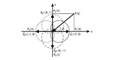
- FIG. 2 is a conceptual diagram when a sound field where a single plane wave arrives at the sound receiving unit is interpreted as a vector.
- FIG. 3 is a block diagram for explaining the configuration of the acoustic measurement apparatus of the present invention.
- FIG. 4 is a diagram for explaining a first embodiment of the acoustic measurement apparatus of the present invention.
- FIG. 5 is a view for explaining a second embodiment of the acoustic measurement apparatus of the present invention.
- FIG. 6 is a simulation result of the second embodiment of the acoustic measurement device of the present invention when the direction of arrival of the sound from the sound source is changed with respect to the horizontal angle.
- FIG. 1 is a conceptual diagram when a sound field in which a single plane wave arrives at a sound receiving unit is assumed.
- FIG. 2 is a conceptual diagram when a sound field where a single plane wave arrives at
- FIG. 7 is a simulation result of the second embodiment of the acoustic measurement device of the present invention when the direction of arrival is changed with respect to the elevation angle.
- FIG. 8 is a simulation result of obtaining the absolute value of the sound intensity by the second embodiment of the sound measuring apparatus of the present invention.
- FIG. 1 is a conceptual diagram when a sound field in which a single plane wave arrives at a sound receiving unit is assumed. As illustrated, assuming a sound field in which a single plane wave P (t) arrives at an angle ⁇ with respect to the x direction, the particle velocity u (t) in the sound field traveling direction is expressed by the following equation. Where ⁇ c is acoustic impedance.
- the particle velocity u x (t) in the x direction is expressed by the following equation.
- the x direction component of the sound intensity is expressed by the following equation.
- Equation 7 Comparing Equation 7 with Equation 2, it can be seen that the particle velocity u x (t) in the x direction is obtained from the difference between the responses of the microphone 1 and the microphone 2 as in the following equation.
- the sound intensity component in the x direction is expressed as follows.
- Equation 9 can also be expressed as follows.
- the sound intensity component in each direction may be obtained in the same manner as the above-described theory, and if the sound intensity component in each direction is synthesized. , The sound intensity I (t) is obtained.
- the sound intensity component of each dimension is obtained by the difference and addition of the microphone pair of each dimension.
- the sound intensity is obtained based on such a theory.
- FIG. 2 is a conceptual diagram when a sound field where a single plane wave arrives at the sound receiving unit is interpreted as a vector.
- unit vectors e 1 to e 4 that point in the direction of maximum sensitivity of the microphone as shown.
- the unit vector e 1 in which the maximum sensitivity direction of the microphone is directed on the x-axis of the orthogonal coordinates has a component of (1, 0).
- n is the number of microphones (number of channels)
- K is a particle velocity normalization coefficient that varies depending on the number of channels and the type of microphone.
- the particle velocity vector is expressed as a vector synthesized by multiplying (weighting) each measured value of a plurality of microphones by each unit vector. That is, when the particle velocity vector is calculated as the acoustic information, each unit vector is multiplied by the sound pressure of each of the plurality of microphones, and this is vector-synthesized.
- the omnidirectional sound pressure is expressed as the sum of the sound pressures of the plurality of microphones. That is, when calculating omnidirectional sound pressure as acoustic information, the sum of sound pressures of a plurality of microphones may be obtained.
- the sound intensity is represented by the product of the particle velocity vector thus obtained and the omnidirectional sound pressure. That is, when the sound intensity is calculated as the sound information, the particle velocity vector and the omnidirectional sound pressure may be multiplied.
- the sound intensity I (t) is expressed by the following equation.
- G is a normalization coefficient that varies depending on the number of channels and the type of microphone.
- the acoustic intensity can be directly calculated without obtaining the particle velocity vector when the square sound pressure is considered. That is, when calculating the sound intensity as the sound information, each unit vector is multiplied by the square sound pressure, and this is vector-synthesized.
- the vector synthesis method of the CC type acoustic measurement device may be performed according to such a theory. Note that vector synthesis includes not only adding vectors but also subtracting from the opposite direction.
- unit vectors facing the maximum sensitivity direction of each microphone must be spatially balanced. That is, a plurality of microphones are arranged so that the sum of each unit vector becomes zero.
- the contribution of each dimension is equal as expressed in the following equation. That is, it is arranged so that the sum of the squares of the components of the unit vectors of the plurality of microphones is equal.
- the number of microphones should be larger than the number of spatial dimensions of the calculated acoustic information vector.
- the vector synthesis method of the acoustic measurement device of the present invention can be used.
- the condition of (2) is not necessarily essential, and even if the microphone placement is such that the contribution of each dimension is not equal, it can be dealt with by appropriately correcting if the condition of (1) is satisfied. It is.
- FIG. 3 is a block diagram for explaining the configuration of the acoustic measurement apparatus of the present invention.
- the acoustic measurement device of the present invention mainly includes a sound receiving unit 10 and a calculation unit 20.
- the sound receiving unit 10 has a plurality of microphones, and each microphone has unidirectionality.
- each of the plurality of microphones is configured such that the sum of unit vectors facing the maximum sensitivity direction becomes zero and each component of each unit vector. Are arranged so that the sum of the squares of is equal. The arrangement positions of the plurality of microphones will be described later.
- the microphone has unidirectionality. More specifically, these include a cardioid microphone, a super cardioid microphone, a hyper cardioid microphone, an ultra cardioid microphone, and the like. Note that the response (sound pressure) characteristics measured by each microphone may be appropriately changed according to the difference in the directivity characteristics of the microphones used.
- the information measured by the sound receiving unit is sent to the calculation unit 20.
- the computing unit 20 is composed of a computing device such as a personal computer or a digital signal processor (DSP).
- the calculation unit 20 calculates omnidirectional sound pressure, particle velocity vector, and sound intensity according to the application of the sound measurement device and the like. For example, when the omnidirectional sound pressure is obtained, the sound pressures of the plurality of microphones may be summed using Equation 11. Further, when obtaining the particle velocity vector, the sound pressure of each of the plurality of microphones is multiplied by each unit vector by using Equation 12, and the vector synthesis is performed. Furthermore, when obtaining the sound intensity, the particle velocity vector and the omnidirectional sound pressure may be multiplied. These may be calculated in combination as appropriate.
- the arithmetic unit 20 uses Equation 14 to square the sound pressure of each of the plurality of microphones, multiply the squared sound pressure by each unit vector, and obtain a sound intensity by performing vector synthesis. May be.
- FIG. 4 is a diagram for explaining the sound receiving unit of the first embodiment of the acoustic measurement apparatus of the present invention.
- the acoustic measuring device of the first embodiment is for measuring two-dimensional acoustic information.
- the microphones constituting the sound receiving unit are composed of three microphones, a first microphone 11, a second microphone 12, and a third microphone 13.
- an arrow pointing in the direction of maximum sensitivity of the microphone represents a unit vector.
- Each microphone is arranged so that each unit vector faces in a direction from the center of gravity of the triangle toward each vertex.
- the direction of the unit vector may be reversed.
- the microphones may be arranged so that the unit vector faces in the direction from each vertex of the triangle toward the center of gravity.
- the plurality of microphones are arranged so that the sum of the unit vectors facing the maximum sensitivity direction becomes zero and the sum of the squares of the respective components of each unit vector is equal. If there are three microphones, the unit vectors are arranged in the direction from the center of gravity of the regular triangle toward each vertex.
- the acoustic measurement apparatus of the present invention it is possible to interpret a sound field as a vector by adopting such a microphone arrangement.
- the acoustic measurement device of the present invention requires a minimum of four microphones for measuring two-dimensional particle velocity vectors and acoustic intensity in the past. It will be enough. Even in such a configuration, the particle velocity vector and the sound intensity can be easily obtained by using the equations 12 and 13.
- the number of microphones is not necessarily limited to three, and four, five, or more can be used depending on the application.
- the four microphones satisfying the above conditions (1) to (3) are arranged at right angles in the x-axis direction and the y-axis direction with the microphone pair arranged in the opposite direction of 180 degrees centering on the origin of the coordinates. It will be arranged to do.
- the configuration that can ignore the inconsistency of the inherent phase characteristics existing between the microphones is when four or more microphones are used. Therefore, strictly speaking, in the case of a sound receiving unit composed of three microphones, a measurement error due to a mismatch in phase characteristics may occur, but a sufficient effect can be obtained as compared with the conventional PP method.
- the interval between the plurality of microphones is not affected as long as it is a single plane wave sound field, but in the case of a plurality of interference sound fields, the interval is preferably close.
- the sound receiving unit may be configured using a number of microphones. Therefore, if the sound receiving unit is configured by using a large number of microphones, even if one microphone breaks down, the function as an acoustic measurement device can be ensured to some extent although the measurement accuracy is lowered. Therefore, it can be applied to uses where robustness is required.
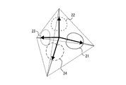
- FIG. 5 is a diagram for explaining the sound receiving unit of the second embodiment of the acoustic measurement apparatus of the present invention.
- the acoustic measurement device of the first embodiment is for measuring two-dimensional acoustic information
- the acoustic measurement device of the second embodiment is for measuring three-dimensional acoustic information.
- the microphones constituting the sound receiving unit are composed of four microphones: a first microphone 21, a second microphone 22, a third microphone 23, and a fourth microphone 24.
- an arrow pointing in the direction of maximum sensitivity of the microphone represents a unit vector.
- Each microphone is arranged so that each unit vector faces in a direction from the center of gravity of the triangular pyramid (tetrahedron) toward each vertex.
- the direction of the unit vector may be reversed.
- the microphones may be arranged so that the unit vector faces in a direction from each vertex of the triangular pyramid toward the center of gravity.
- the plurality of microphones are arranged so that the sum of the unit vectors facing the maximum sensitivity direction becomes zero and the sum of the squares of the respective components of each unit vector is equal.
- the unit vectors are arranged in the direction from the center of gravity of the regular tetrahedron to each vertex.
- the sound field can be interpreted as a vector, and at least six microphones for measuring a three-dimensional particle velocity vector and acoustic intensity are conventionally required. Only a minimum of 4 is enough. Even in such a configuration, the particle velocity vector and the sound intensity can be easily obtained by using the equations 12 and 13.
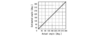
- FIG. 6 shows a simulation result of the second embodiment of the acoustic measurement device of the present invention when the direction of arrival of the sound from the sound source is changed with respect to the horizontal angle.
- the horizontal axis represents the actual sound arrival direction
- the vertical axis represents the sound arrival direction based on the calculation result.
- FIG. 7 is a simulation result of the second embodiment of the acoustic measurement device of the present invention when the direction of arrival is changed with respect to the elevation angle.
- the horizontal axis is the actual sound arrival direction
- the vertical axis is the sound arrival direction according to the calculation result.
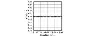
- FIG. 8 is a simulation result of obtaining the absolute value of the sound intensity in the configuration of the second embodiment of the sound measuring apparatus of the present invention.
- the horizontal axis is the actual direction of arrival of the sound
- the vertical axis is the absolute value of the sound intensity according to the calculation result.
- the three-dimensional arrival direction can be analyzed with high accuracy. It can also be seen that the absolute value of the sound intensity is the same regardless of the direction of arrival of the sound, and the analysis can be performed without deviation with respect to the direction of the sound source.
- the measurement theory based on the CC method is interpreted as a vector, and therefore there is no frequency dependency of the distance between the microphones, which is an effect of the CC method. Furthermore, since it is not necessary to arrange a plurality of microphones on each axis of orthogonal coordinates in the opposite direction of 180 degrees, the number of microphones can be reduced.
- the microphones it is not necessary to arrange the directivities of the microphones 180 degrees opposite to each other, and the microphones can be arranged obliquely, so that the microphones are usually placed at positions facing the sound receiving side of the microphones.
- the provided terminals are difficult to physically interfere with each other. Therefore, the microphone can be easily arranged and downsized.
- the number of microphones is not necessarily limited to four, and five, six, or more can be used depending on the application.
- the arrangement positions of the six microphones satisfying the above conditions (1) to (3) are the microphone pairs arranged in the opposite directions of 180 degrees, with the origin of the coordinates as the center, the x-axis direction, the y-axis direction, and z They are arranged so as to be orthogonal in the axial direction.
- a configuration that can ignore the inconsistency of the inherent phase characteristics existing between the microphones is when six or more microphones are used. Therefore, strictly speaking, in the case of a sound receiving unit composed of four microphones, a measurement error due to mismatch of phase characteristics may occur, but a sufficient effect can be obtained as compared with the conventional PP method.
- the interval between the plurality of microphones is not affected if it is a single sound field, but in the case of a plurality of interference sound fields, it is preferable that the intervals be closer.
- the sound receiving unit may be configured using a number of microphones. Therefore, if the sound receiving unit is configured by using a large number of microphones, even if one microphone breaks down, the function as an acoustic measurement device can be ensured to some extent although the measurement accuracy is lowered. Therefore, it can be applied to uses where robustness is required.
- acoustic measurement device of the present invention is not limited to the illustrated example described above, and it is needless to say that various changes can be made without departing from the gist of the present invention.
Landscapes
- Physics & Mathematics (AREA)
- Health & Medical Sciences (AREA)
- Otolaryngology (AREA)
- Engineering & Computer Science (AREA)
- Acoustics & Sound (AREA)
- Signal Processing (AREA)
- General Physics & Mathematics (AREA)
- Multimedia (AREA)
- Obtaining Desirable Characteristics In Audible-Bandwidth Transducers (AREA)
- Circuit For Audible Band Transducer (AREA)
- Measurement Of Mechanical Vibrations Or Ultrasonic Waves (AREA)
Abstract
Description
10 受音部
11~13 マイクロホン(指向性)
20 演算部
21~24 マイクロホン(指向性)












(1)次式に表されるように、各マイクロホンの感度最大方向を向く単位ベクトルが空間的にバランスしていること。即ち、各単位ベクトルの総和がゼロとなるように複数のマイクロホンが配置されること。


Claims (11)
- 音響測定装置であって、該装置は、
単一指向性の複数のマイクロホンを有する受音部であって、前記複数のマイクロホンは、その感度最大方向を向く単位ベクトルの総和がゼロとなるように配置される、受音部と、
前記受音部の複数のマイクロホンのそれぞれの測定値を各単位ベクトルに乗算し、そのベクトル合成を用いて音響情報を算出する演算部と、
を具備することを特徴とする音響測定装置。 - 請求項1に記載の音響測定装置において、前記受音部の複数のマイクロホンは、それぞれの単位ベクトルのそれぞれの成分の2乗の総和が等しくなるように配置されることを特徴とする音響測定装置。
- 請求項1又は請求項2に記載の音響測定装置において、前記受音部の複数のマイクロホンは、その数が、算出する音響情報の空間次元数よりも多いことを特徴とする音響測定装置。
- 請求項1乃至請求項3の何れかに記載の音響測定装置において、前記受音部の複数のマイクロホンのそれぞれの測定値が音圧であり、前記演算部は、複数のマイクロホンのそれぞれの音圧を各単位ベクトルに乗算し、そのベクトル合成である粒子速度ベクトルを算出することを特徴とする音響測定装置。
- 請求項1乃至請求項4の何れかに記載の音響測定装置において、前記受音部の複数のマイクロホンのそれぞれの測定値が音圧であり、前記演算部は、さらに、複数のマイクロホンのそれぞれの音圧の総和である無指向性の音圧を算出することを特徴とする音響測定装置。
- 請求項5に記載の音響測定装置において、前記演算部は、粒子速度ベクトルと無指向性の音圧を乗算して音響インテンシティを算出することを特徴とする音響測定装置。
- 請求項1乃至請求項3の何れかに記載の音響測定装置において、前記受音部の複数のマイクロホンのそれぞれの測定値が音圧であり、前記演算部は、複数のマイクロホンのそれぞれの音圧の2乗を各単位ベクトルに乗算し、そのベクトル合成である音響インテンシティを算出することを特徴とする音響測定装置。
- 請求項1乃至請求項7の何れかに記載の音響測定装置において、前記受音部は3つのマイクロホンからなり、各マイクロホンは三角形の重心から各頂点に向かう方向、又は各頂点から重心に向かう方向に、各単位ベクトルが向くようにそれぞれ配置されることを特徴とする音響測定装置。
- 請求項1乃至請求項7の何れかに記載の音響測定装置において、前記受音部は4つのマイクロホンからなり、各マイクロホンは三角錐の重心から各頂点に向かう方向、又は各頂点から重心に向かう方向に、各単位ベクトルが向くようにそれぞれ配置されることを特徴とする音響測定装置。
- 請求項1乃至請求項9の何れかに記載の音響測定装置において、前記受音部の複数のマイクロホンは、それぞれカーディオイドマイクロホン、スーパーカーディオイドマイクロホン、ハイパーカーディオイドマイクロホン、ウルトラカーディオイドマイクロホンの何れかであることを特徴とする音響測定装置。
- 音響測定装置であって、該装置は、
単一指向性の複数のマイクロホンを有する受音部であって、前記複数のマイクロホンは、その感度最大方向を向く単位ベクトルの総和がゼロとなるように配置される、受音部と、
前記受音部の複数のマイクロホンのそれぞれの測定値を総和して音響情報を算出する演算部と、
を具備することを特徴とする音響測定装置。
Priority Applications (4)
| Application Number | Priority Date | Filing Date | Title |
|---|---|---|---|
| CN2009801080710A CN101971248B (zh) | 2008-03-07 | 2009-03-05 | 声测定装置 |
| US12/921,389 US9121752B2 (en) | 2008-03-07 | 2009-03-05 | Acoustic measurement device |
| KR1020107019977A KR101240733B1 (ko) | 2008-03-07 | 2009-03-05 | 음향 측정 장치 |
| GB1015148.8A GB2470164B (en) | 2008-03-07 | 2009-03-05 | Acoustic measurement device |
Applications Claiming Priority (2)
| Application Number | Priority Date | Filing Date | Title |
|---|---|---|---|
| JP2008057260A JP5156934B2 (ja) | 2008-03-07 | 2008-03-07 | 音響測定装置 |
| JP2008-057260 | 2008-03-07 |
Publications (1)
| Publication Number | Publication Date |
|---|---|
| WO2009110239A1 true WO2009110239A1 (ja) | 2009-09-11 |
Family
ID=41055804
Family Applications (1)
| Application Number | Title | Priority Date | Filing Date |
|---|---|---|---|
| PCT/JP2009/000994 Ceased WO2009110239A1 (ja) | 2008-03-07 | 2009-03-05 | 音響測定装置 |
Country Status (6)
| Country | Link |
|---|---|
| US (1) | US9121752B2 (ja) |
| JP (1) | JP5156934B2 (ja) |
| KR (1) | KR101240733B1 (ja) |
| CN (1) | CN101971248B (ja) |
| GB (1) | GB2470164B (ja) |
| WO (1) | WO2009110239A1 (ja) |
Cited By (3)
| Publication number | Priority date | Publication date | Assignee | Title |
|---|---|---|---|---|
| US8798955B2 (en) | 2008-06-20 | 2014-08-05 | Nihon University | Acoustic energy measurement device, and acoustic performance evaluation device and acoustic information measurement device using the same |
| CN107154256A (zh) * | 2017-06-27 | 2017-09-12 | 山东省计算中心(国家超级计算济南中心) | 基于声源定位的声掩蔽系统及自适应调整方法 |
| JP2020148763A (ja) * | 2019-03-15 | 2020-09-17 | 株式会社日立製作所 | 無指向性の可聴雑音源の位置特定機器 |
Families Citing this family (8)
| Publication number | Priority date | Publication date | Assignee | Title |
|---|---|---|---|---|
| JP5156934B2 (ja) | 2008-03-07 | 2013-03-06 | 学校法人日本大学 | 音響測定装置 |
| CA2729744C (en) | 2008-06-30 | 2017-01-03 | Constellation Productions, Inc. | Methods and systems for improved acoustic environment characterization |
| EP2448289A1 (en) | 2010-10-28 | 2012-05-02 | Fraunhofer-Gesellschaft zur Förderung der angewandten Forschung e.V. | Apparatus and method for deriving a directional information and computer program product |
| EP3304043B1 (fr) * | 2015-06-02 | 2022-03-09 | Centre National de la Recherche Scientifique (CNRS) | Procedes et systemes d'imagerie acousto-optique |
| JP2017075780A (ja) * | 2015-10-13 | 2017-04-20 | 日産自動車株式会社 | 高周波音測定装置 |
| CN106199518A (zh) * | 2016-07-12 | 2016-12-07 | 江门职业技术学院 | 一种声源方位角定位方法 |
| JP7136445B2 (ja) * | 2018-08-29 | 2022-09-13 | 学校法人日本大学 | 音響情報測定装置、音響情報測定方法、及びプログラム |
| CN113340409B (zh) * | 2021-06-07 | 2024-06-28 | 广电计量检测集团股份有限公司 | 体积声源的校准方法、装置、计算机设备和存储介质 |
Citations (2)
| Publication number | Priority date | Publication date | Assignee | Title |
|---|---|---|---|---|
| JPH0236318A (ja) * | 1988-07-26 | 1990-02-06 | Ichikawa:Kk | 音響インテンシティ装置 |
| WO2006054599A1 (ja) * | 2004-11-16 | 2006-05-26 | Nihon University | 音源方向判定装置及び方法 |
Family Cites Families (18)
| Publication number | Priority date | Publication date | Assignee | Title |
|---|---|---|---|---|
| JPS63295932A (ja) * | 1987-05-28 | 1988-12-02 | Nec Corp | 音響インテンシテイ測定装置 |
| JPH06194217A (ja) | 1992-12-24 | 1994-07-15 | Sekisui House Ltd | 現場に於ける住宅音響性能測定装置 |
| JPH06201450A (ja) | 1992-12-30 | 1994-07-19 | Tokyo Gas Co Ltd | 音響インテンシティプローブ |
| US5664021A (en) * | 1993-10-05 | 1997-09-02 | Picturetel Corporation | Microphone system for teleconferencing system |
| JP3544271B2 (ja) | 1996-09-24 | 2004-07-21 | アルパイン株式会社 | 音場制御方法 |
| US6173059B1 (en) * | 1998-04-24 | 2001-01-09 | Gentner Communications Corporation | Teleconferencing system with visual feedback |
| JP2000261900A (ja) | 1999-03-09 | 2000-09-22 | Sony Corp | 音場補正方法および音響装置。 |
| JP3863323B2 (ja) | 1999-08-03 | 2006-12-27 | 富士通株式会社 | マイクロホンアレイ装置 |
| JP2005202014A (ja) | 2004-01-14 | 2005-07-28 | Sony Corp | 音声信号処理装置、音声信号処理方法および音声信号処理プログラム |
| JP4127248B2 (ja) * | 2004-06-23 | 2008-07-30 | ヤマハ株式会社 | スピーカアレイ装置及びスピーカアレイ装置の音声ビーム設定方法 |
| US7327849B2 (en) | 2004-08-09 | 2008-02-05 | Brigham Young University | Energy density control system using a two-dimensional energy density sensor |
| JP4066197B2 (ja) * | 2005-02-24 | 2008-03-26 | ソニー株式会社 | マイクロフォン装置 |
| JP2007054909A (ja) | 2005-08-24 | 2007-03-08 | Ngk Insulators Ltd | ワイヤーソー加工方法 |
| JP2007292667A (ja) | 2006-04-26 | 2007-11-08 | Isuzu Motors Ltd | 音響特性測定装置 |
| US8068619B2 (en) * | 2006-05-09 | 2011-11-29 | Fortemedia, Inc. | Method and apparatus for noise suppression in a small array microphone system |
| JP2008057260A (ja) | 2006-09-01 | 2008-03-13 | Nishikawa Rubber Co Ltd | 目地の防水構造 |
| JP2008249702A (ja) | 2007-03-05 | 2008-10-16 | Univ Nihon | 音響測定装置及び音響測定方法 |
| JP5156934B2 (ja) | 2008-03-07 | 2013-03-06 | 学校法人日本大学 | 音響測定装置 |
-
2008
- 2008-03-07 JP JP2008057260A patent/JP5156934B2/ja not_active Expired - Fee Related
-
2009
- 2009-03-05 US US12/921,389 patent/US9121752B2/en not_active Expired - Fee Related
- 2009-03-05 GB GB1015148.8A patent/GB2470164B/en not_active Expired - Fee Related
- 2009-03-05 WO PCT/JP2009/000994 patent/WO2009110239A1/ja not_active Ceased
- 2009-03-05 CN CN2009801080710A patent/CN101971248B/zh not_active Expired - Fee Related
- 2009-03-05 KR KR1020107019977A patent/KR101240733B1/ko not_active Expired - Fee Related
Patent Citations (2)
| Publication number | Priority date | Publication date | Assignee | Title |
|---|---|---|---|---|
| JPH0236318A (ja) * | 1988-07-26 | 1990-02-06 | Ichikawa:Kk | 音響インテンシティ装置 |
| WO2006054599A1 (ja) * | 2004-11-16 | 2006-05-26 | Nihon University | 音源方向判定装置及び方法 |
Non-Patent Citations (1)
| Title |
|---|
| SHUN OGURO ET AL.: "Sanjigen Onkyo Intensity Probe", IEICE TECHNICAL REPORT, (EA9247-55), vol. 92, no. 191, 25 August 1992 (1992-08-25), pages 59 - 62 * |
Cited By (4)
| Publication number | Priority date | Publication date | Assignee | Title |
|---|---|---|---|---|
| US8798955B2 (en) | 2008-06-20 | 2014-08-05 | Nihon University | Acoustic energy measurement device, and acoustic performance evaluation device and acoustic information measurement device using the same |
| CN107154256A (zh) * | 2017-06-27 | 2017-09-12 | 山东省计算中心(国家超级计算济南中心) | 基于声源定位的声掩蔽系统及自适应调整方法 |
| CN107154256B (zh) * | 2017-06-27 | 2023-11-24 | 山东省计算中心(国家超级计算济南中心) | 基于声源定位的声掩蔽系统及自适应调整方法 |
| JP2020148763A (ja) * | 2019-03-15 | 2020-09-17 | 株式会社日立製作所 | 無指向性の可聴雑音源の位置特定機器 |
Also Published As
| Publication number | Publication date |
|---|---|
| GB201015148D0 (en) | 2010-10-27 |
| KR101240733B1 (ko) | 2013-03-11 |
| CN101971248A (zh) | 2011-02-09 |
| GB2470164A (en) | 2010-11-10 |
| CN101971248B (zh) | 2013-01-23 |
| US9121752B2 (en) | 2015-09-01 |
| KR20100126727A (ko) | 2010-12-02 |
| US20110103601A1 (en) | 2011-05-05 |
| JP2009216747A (ja) | 2009-09-24 |
| GB2470164B (en) | 2012-08-15 |
| JP5156934B2 (ja) | 2013-03-06 |
Similar Documents
| Publication | Publication Date | Title |
|---|---|---|
| JP5156934B2 (ja) | 音響測定装置 | |
| JP5093702B2 (ja) | 音響エネルギ計測装置並びにこれを用いた音響性能評価装置及び音響情報計測装置 | |
| JP5686358B2 (ja) | 音源距離計測装置及びそれを用いた音響情報分離装置 | |
| JP3863323B2 (ja) | マイクロホンアレイ装置 | |
| JP5814476B2 (ja) | 空間パワー密度に基づくマイクロフォン位置決め装置および方法 | |
| CN107155344A (zh) | 平面传感器阵列 | |
| JPWO2004079388A1 (ja) | 位置情報推定装置、その方法、及びプログラム | |
| Jo et al. | Parametric direction-of-arrival estimation with three recurrence relations of spherical harmonics | |
| US7839721B1 (en) | Modal beam processing of acoustic vector sensor data | |
| Wajid et al. | Design and analysis of air acoustic vector-sensor configurations for two-dimensional geometry | |
| CN112385245A (zh) | 灵活地理分布的差分麦克风阵列和相关波束形成器 | |
| Todorović et al. | Implementation and application of FPGA platform with digital MEMS microphone array | |
| Ma et al. | Real-time separation of non-stationary sound fields on spheres | |
| Politis et al. | Direction-of-arrival and diffuseness estimation above spatial aliasing for symmetrical directional microphone arrays | |
| Burgess et al. | Node localization in unsynchronized time of arrival sensor networks | |
| Ding et al. | DOA estimation of multiple speech sources by selecting reliable local sound intensity estimates | |
| Chen et al. | Estimation of the direct-to-reverberant energy ratio using a spherical microphone array | |
| KR100730297B1 (ko) | 머리전달함수 데이터베이스를 이용한 음원 위치 추정 방법 | |
| Lee et al. | Direction-of-arrival estimation with blind surface impedance compensation for spherical microphone array | |
| JP5839456B2 (ja) | 音響インテンシティ計測方法及び装置 | |
| Jo et al. | Extended vector-based EB-ESPRIT using additional constraints for increasing the maximum number of detectable sources | |
| Liaquat et al. | Sound localization for ad-hoc microphone arrays. Energies 2021, 14, 3446 | |
| Ge et al. | Geometry calibration for deformable linear microphone arrays with Bézier curve fitting | |
| Han et al. | Modified Differential Beamforming Method for Compact Acoustic Vector Sensor Arrays Under Multipath Effects | |
| Zhu et al. | A user-friendly, cost-effective and portable tool for locating multiple arbitrary sound sources in 3D space in real time |
Legal Events
| Date | Code | Title | Description |
|---|---|---|---|
| WWE | Wipo information: entry into national phase |
Ref document number: 200980108071.0 Country of ref document: CN |
|
| 121 | Ep: the epo has been informed by wipo that ep was designated in this application |
Ref document number: 09716362 Country of ref document: EP Kind code of ref document: A1 |
|
| WWE | Wipo information: entry into national phase |
Ref document number: 5531/CHENP/2010 Country of ref document: IN |
|
| ENP | Entry into the national phase |
Ref document number: 20107019977 Country of ref document: KR Kind code of ref document: A |
|
| NENP | Non-entry into the national phase |
Ref country code: DE |
|
| ENP | Entry into the national phase |
Ref document number: 1015148 Country of ref document: GB Kind code of ref document: A Free format text: PCT FILING DATE = 20090305 |
|
| WWE | Wipo information: entry into national phase |
Ref document number: 1015148.8 Country of ref document: GB |
|
| WWE | Wipo information: entry into national phase |
Ref document number: 12921389 Country of ref document: US |
|
| 122 | Ep: pct application non-entry in european phase |
Ref document number: 09716362 Country of ref document: EP Kind code of ref document: A1 |