WO2009104872A2 - 자석 유전체를 이용한 메타머티리얼 안테나 - Google Patents
자석 유전체를 이용한 메타머티리얼 안테나 Download PDFInfo
- Publication number
- WO2009104872A2 WO2009104872A2 PCT/KR2009/000520 KR2009000520W WO2009104872A2 WO 2009104872 A2 WO2009104872 A2 WO 2009104872A2 KR 2009000520 W KR2009000520 W KR 2009000520W WO 2009104872 A2 WO2009104872 A2 WO 2009104872A2
- Authority
- WO
- WIPO (PCT)
- Prior art keywords
- substrate
- srr
- antenna
- metamaterial antenna
- dielectric
- Prior art date
Links
Images


Classifications
-
- H—ELECTRICITY
- H01—ELECTRIC ELEMENTS
- H01Q—ANTENNAS, i.e. RADIO AERIALS
- H01Q1/00—Details of, or arrangements associated with, antennas
- H01Q1/12—Supports; Mounting means
- H01Q1/22—Supports; Mounting means by structural association with other equipment or articles
- H01Q1/24—Supports; Mounting means by structural association with other equipment or articles with receiving set
-
- H—ELECTRICITY
- H01—ELECTRIC ELEMENTS
- H01Q—ANTENNAS, i.e. RADIO AERIALS
- H01Q13/00—Waveguide horns or mouths; Slot antennas; Leaky-waveguide antennas; Equivalent structures causing radiation along the transmission path of a guided wave
- H01Q13/20—Non-resonant leaky-waveguide or transmission-line antennas; Equivalent structures causing radiation along the transmission path of a guided wave
- H01Q13/28—Non-resonant leaky-waveguide or transmission-line antennas; Equivalent structures causing radiation along the transmission path of a guided wave comprising elements constituting electric discontinuities and spaced in direction of wave propagation, e.g. dielectric elements or conductive elements forming artificial dielectric
-
- H—ELECTRICITY
- H01—ELECTRIC ELEMENTS
- H01Q—ANTENNAS, i.e. RADIO AERIALS
- H01Q1/00—Details of, or arrangements associated with, antennas
- H01Q1/36—Structural form of radiating elements, e.g. cone, spiral, umbrella; Particular materials used therewith
- H01Q1/38—Structural form of radiating elements, e.g. cone, spiral, umbrella; Particular materials used therewith formed by a conductive layer on an insulating support
-
- H—ELECTRICITY
- H01—ELECTRIC ELEMENTS
- H01Q—ANTENNAS, i.e. RADIO AERIALS
- H01Q15/00—Devices for reflection, refraction, diffraction or polarisation of waves radiated from an antenna, e.g. quasi-optical devices
- H01Q15/0006—Devices acting selectively as reflecting surface, as diffracting or as refracting device, e.g. frequency filtering or angular spatial filtering devices
- H01Q15/0086—Devices acting selectively as reflecting surface, as diffracting or as refracting device, e.g. frequency filtering or angular spatial filtering devices said selective devices having materials with a synthesized negative refractive index, e.g. metamaterials or left-handed materials
-
- H—ELECTRICITY
- H01—ELECTRIC ELEMENTS
- H01Q—ANTENNAS, i.e. RADIO AERIALS
- H01Q15/00—Devices for reflection, refraction, diffraction or polarisation of waves radiated from an antenna, e.g. quasi-optical devices
- H01Q15/02—Refracting or diffracting devices, e.g. lens, prism
- H01Q15/08—Refracting or diffracting devices, e.g. lens, prism formed of solid dielectric material
-
- H—ELECTRICITY
- H01—ELECTRIC ELEMENTS
- H01Q—ANTENNAS, i.e. RADIO AERIALS
- H01Q9/00—Electrically-short antennas having dimensions not more than twice the operating wavelength and consisting of conductive active radiating elements
- H01Q9/04—Resonant antennas
- H01Q9/0407—Substantially flat resonant element parallel to ground plane, e.g. patch antenna
-
- H—ELECTRICITY
- H01—ELECTRIC ELEMENTS
- H01Q—ANTENNAS, i.e. RADIO AERIALS
- H01Q9/00—Electrically-short antennas having dimensions not more than twice the operating wavelength and consisting of conductive active radiating elements
- H01Q9/04—Resonant antennas
- H01Q9/0485—Dielectric resonator antennas
Definitions
- the present invention relates to the miniaturization of antenna size by using a magneto-dielectric material in a CRLH-TL antenna.
- the present invention relates to a SRR in a CRLH-TL antenna implemented by using a patch and vias.
- the present invention relates to a metamaterial antenna using a magnet dielectric which magnetizes a dielectric and reduces its size.
- Metamaterial refers to a material having electromagnetic properties that do not exist in nature by periodically arranging specific unit structures.
- NRI Negative Refractive Index
- LHM Left-Handed Material
- the performance of the antenna can be improved by applying the characteristics of the metamaterial to the antenna.
- the metamaterial structure applied to the antenna is typical of the Composite Right / Left Handed Transmission Line (CRLH-TL) structure.
- CRLH-TL Composite Right / Left Handed Transmission Line
- One of the characteristics of this structure, the zero-order resonant mode is a resonant mode in which the propagation constant becomes zero. The wavelength becomes infinite and no phase delay occurs due to the radio wave transmission.
- the resonant frequency of this mode is determined by the parameters of the CRLH-TL structure, and thus is not dependent on the antenna length, which is very advantageous for miniaturization of the antenna.
- the antenna can be made using the first resonant mode, which has the same radiation pattern as a general patch antenna and can be designed with a very low resonance frequency.
- a conventional method of miniaturizing the size of an antenna is to use a high dielectric constant substrate.
- energy is trapped in the substrate of high dielectric constant and thus has side effects such as lowering antenna efficiency and narrowing bandwidth.
- a substrate having a high permeability is used, this problem can be solved and the antenna can be miniaturized.
- a metal structure responding to a magnetic field applied to the outside is inserted into a general substrate.
- the main structure used is Split Ring Resonator (SRR), in which current is induced in SRR by an external magnetic field and magnetic field is generated thereby to change permeability according to the external magnetic field.
- SRR Split Ring Resonator
- Permeability exhibits a resonant characteristic.
- the permeability value is greater than 1 in the band below the resonant frequency, has a negative permeability value between the plasma frequency at the resonant frequency, and is less than 1 above the plasma frequency.
- the band used as the magnetic dielectric is in the region below the resonance frequency.
- the present invention devised to solve the above problem relates to the miniaturization of the antenna size by using a magneto-dielectric material in the CRLH-TL antenna, in particular using a patch (via) and via (via) It is an object of the present invention to provide a metamaterial antenna using a magnetic dielectric that reduces the size by magnetizing a dielectric using SRR in the implemented CRLH-TL antenna.
- the substrate is inserted into the SRR (Split Ring Resonator) structure is a magnetic dielectric; Patch of CRLH-TL (Composite Right / Left Handed Transmission Line) structure formed on the substrate spaced apart from the substrate by a predetermined distance; And it provides a metamaterial antenna using a magnetic dielectric comprising a ground formed in the lower portion spaced apart from the substrate.
- SRR Split Ring Resonator
- CRLH-TL Composite Right / Left Handed Transmission Line
- the substrate, patch and ground utilize a magnetic dielectric interconnected via vias.
- the substrate includes an SRR structure consisting of two unit cells, and one unit cell of the SRR structure is formed by arranging eight SRRs radially.
- one unit cell of the SRR structure has six relatively long first SRRs radially disposed in the longitudinal direction of the substrate 200, and a second short SRR is disposed horizontally, and the first and second SRRs are arranged horizontally.
- the second SRR is formed to face each other on the top and bottom surfaces of the substrate.
- both ends of the first and second SRRs formed to face each other on the top and bottom surfaces of the substrate are connected through vias passing through the substrate.
- slots are formed in the central portions of the first and second SRRs formed on the lower surface of the substrate.
- the patch is a CRLH-TL antenna of two unit cells (unit-cell).
- the patch is coupled to the microstrip line that is a feed line (feed line) is spaced apart at a predetermined interval.
- the present invention provides a wireless communication terminal including the metamaterial antenna.
- the present invention relates to miniaturization of the antenna size by using a magneto-dielectric material in the CRLH-TL antenna, and particularly, by using a patch and vias.
- the CRLH-TL antenna can be provided with a metamaterial antenna using a magnetic dielectric that uses SRR to magnetize the dielectric to reduce its size.
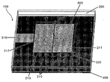
- FIG. 1 is a diagram illustrating a metamaterial antenna using a magnetic dielectric according to a preferred embodiment of the present invention.
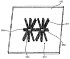
- Figure 2 shows a substrate made of a magnetic dielectric in accordance with one preferred embodiment of the present invention.
- FIG. 3 is a diagram illustrating an SRR structure according to an embodiment of the present invention.
- FIG. 4 is a view showing a direction of generation of a magnetic field in an antenna according to an embodiment of the present invention.
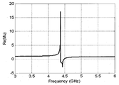
- FIG. 5 is a view showing a change in permeability according to the frequency of the first SRR according to an embodiment of the present invention.
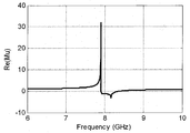
- FIG. 6 is a view showing a change in permeability according to the frequency of the second SRR according to an embodiment of the present invention.
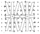
- FIG. 8 is a view showing surface current of SRR in a zeroth order resonance mode according to an exemplary embodiment of the present invention.
- FIG. 9 is a view showing a magnetic field direction generated in the antenna according to an embodiment of the present invention.
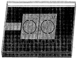
- FIG. 10 is a photograph showing an antenna actually fabricated using the SRR structure according to an embodiment of the present invention.
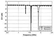
- 11 is a graph showing the measured return loss and the simulated return loss of the actually manufactured antenna.
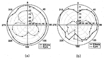
- FIG. 12 is a view showing a measured radiation pattern of the actually manufactured antenna.
- FIG. 1 is a diagram illustrating a metamaterial antenna using a magnetic dielectric according to an exemplary embodiment of the present invention.
- the metamaterial antenna 100 of the CRLH-TL structure uses a magnetic dielectric implemented using a split ring resonator (SRR) structure 210 as a substrate 200. Patch 300 is formed on the top.
- SRR split ring resonator
- the metamaterial antenna 100 is composed of three layers, the patch 300 is formed on the upper surface of the uppermost layer, and the SRR structure 210 is implemented on both sides of the substrate 200 by using the upper and lower surfaces of the substrate 200. .
- the bottom layer acts as ground 400, and the three layers are connected to vias 500.
- the patch 300 is a CRLH-TL antenna implemented with two unit cells, and the lower end of the patch 300 includes an SRR structure 210 having eight SRRs 211 and 212 per unit cell. It is formed to magnetize the dielectric, and the dielectric is used as the substrate 200.
- the feeding of the antenna consists of a microstrip line 310 having a width of 8 mm.
- FIG. 2 is a view showing a substrate made of a magnetic dielectric according to a preferred embodiment of the present invention
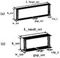
- Figure 3 is a view showing an SRR structure according to a preferred embodiment of the present invention.
- the SRR structure 210 includes a first SRR 211 that is relatively long and a second SRR 212 that is short, and six first SRRs 211 are formed.
- the substrate 200 is radially disposed in the longitudinal direction, and the second SRR 212 is disposed horizontally.
- 3A illustrates a structure of a first SRR 211 and a second SRR 212.
- the first and second SRRs 211 and 212 are formed to be symmetrical on the top and bottom surfaces of the substrate, and both ends of each of the SRRs 211 and 212 facing the substrate may have vias 500 penetrating through the substrate. Connected through.
- slots 213 are formed in the central portions of the first and second SRRs 211 and 212 formed on the lower surface of the substrate.
- FIG. 4 is a diagram illustrating a direction in which a magnetic field is generated in an antenna according to an exemplary embodiment of the present invention.
- the SRR structure 210 In order for the SRR structure 210 to respond to the magnetic field, the SRR structure 210 needs to be perpendicular to the magnetic field direction.
- the CRLH-TL metamaterial antenna 100 implemented using the patch 300 and the via 500 is formed in a direction in which a magnetic field rotates about the via 500. Therefore, it is effective to arrange the first and second SRRs 211 and 212 radially about the vias 500.
- FIG. 5 is a view showing a change in permeability according to the frequency of the first SRR according to an embodiment of the present invention.
- the first SRR 211 showed resonance characteristics at 4.37 GHz. At lower frequencies, the permeability is greater than 1, and at higher frequencies the permeability becomes negative and less than one.
- the frequency range used for the magnetic dielectric is a frequency band lower than the resonant frequency of the SRR, and the permeability value in this band is greater than one.
- FIG. 6 is a view showing a change in permeability according to the frequency of the second SRR according to an embodiment of the present invention.
- the second SRR 212 has a resonance characteristic at 7.91 GHz, and the change pattern of permeability is the same as that of the first SRR 211.
- Coupled feeding was performed between the microstrip line 310, which is a feed line, and the patch 300, with a spacing of 0.3 mm.
- the frequency reduction effect can be obtained for both the 0th-order resonant frequency and the -1st-order resonant frequency when the SRR is not used.
- a frequency reduction effect of 23.9% was obtained.
- the antenna size is 0.1717 ⁇ 0 ⁇ 0.1717 ⁇ 0 ⁇ 0.0176 ⁇ 0 ( ⁇ 0 : wavelength in free space) when SRR is not used, and the size of the antenna using SRR is 0.1306 ⁇ 0 ⁇ 0.1306 ⁇ 0 ⁇ 0.0134
- ⁇ 0 an area reduction effect of about 42.14% was obtained.
- FIG. 8 is a diagram showing surface current of SRR in a zeroth order resonance mode according to an exemplary embodiment of the present invention.
- FIG. 8 shows the current flowing on the upper surface of the SRR when viewed from the top to the bottom, and (b) shows the current flowing on the lower surface of the SRR when viewed from the bottom. Since the current of the via 500 is directed toward the ground 400 in the patch, the direction of the magnetic field becomes clockwise as shown in FIG. 9 when viewed from above. At this time, looking at the direction of the current flowing through the SRR it can be seen that the direction of the magnetic field generated by the SRR will be the same direction as the magnetic field due to the via (500). Therefore, the magnetic permeability is increased by the enhanced magnetic field and the resonance frequency of the antenna is decreased.
- FIG. 10 is a photograph showing an antenna actually manufactured using an SRR structure according to an embodiment of the present invention.
- an antenna was matched by adjusting a distance between a feed line and a patch 300 to 0.5 mm.
- 11 is a graph showing the measured return loss and the simulated return loss of the actually manufactured antenna.
- the via 500 is slightly protruded due to the planar SRR structure up and down, and thus a little gap is generated between the substrates 200. It is judged that the error of the frequency band occurred in the return loss due to the error caused by the gap.
- the measured antenna bandwidth is from 1.883 to 1.892 GHz (0.48%).
- FIG. 12 is a view illustrating measured radiation patterns of an actually manufactured antenna.
- (a) shows an E-plane in the x-z plane
- (b) shows an H-plane in the x-y plane.
- the radiation pattern represents a monopole radiation pattern, which is a radiation pattern of the 0th order resonance mode antenna.
- the measured antenna gain is 0.534 dBi and the efficiency is 51.7%.
Abstract
Description

Claims (9)
- SRR(Split Ring Resonator) 구조가 삽입되어 자석 유전체가 구현된 기판;상기 기판과 소정 간격 이격되어 상부에 형성되는 CRLH-TL(Composite Right/Left Handed Transmission Line) 구조의 패치; 및상기 기판과 소정 간격 이격되어 하부에 형성되는 접지를 포함하는 자석 유전체를 이용한 메타머티리얼 안테나.
- 제 1항에 있어서,상기 기판, 패치 및 접지는 비아를 통하여 상호 연결되는 자석 유전체를 이용한 메타머티리얼 안테나.
- 제 1항에 있어서,상기 기판은 2개의 유닛 셀로 이루어진 SRR 구조를 포함하며,상기 SRR 구조의 한 유닛 셀은 8개의 SRR이 방사상으로 배치되어 형성되는 자석 유전체를 이용한 메타머티리얼 안테나.
- 제 3항에 있어서,상기 SRR 구조의 한 유닛 셀은 상대적으로 길이가 긴 제 1 SRR 6개가 상기 기판(200)의 세로 방향으로 방사형으로 배치되고,길이가 짧은 제 2 SRR이 가로로 배치되며,상기 제 1 및 제 2 SRR은 기판의 위 아래면에 상호 마주보도록 형성되는 자석 유전체를 이용한 메타머티리얼 안테나.
- 제 4항에 있어서,기판의 위 아래면에 상호 마주보도록 형성되는 상기 제 1 및 제 2 SRR의 양 말단은 기판을 관통하는 비아를 통하여 연결되는 자석 유전체를 이용한 메타머티리얼 안테나.
- 제 4항에 있어서,상기 기판의 아랫면에 형성되는 제 1 및 제 2 SRR의 중앙부에는 슬롯이 형성되는 자석 유전체를 이용한 메타머티리얼 안테나.
- 제 1항에 있어서,상기 패치는 2개의 유닛 셀(unit-cell)로 이루어진 CRLH-TL 구조의 안테나인 자석 유전체를 이용한 메타머티리얼 안테나.
- 제 1항에 있어서,상기 패치는 급전선(feed line)인 마이크로스트립 라인과 소정 간격 이격되어 커플급전되는 자석 유전체를 이용한 메타머티리얼 안테나.
- 제 1항 내지 제 8항 중 어느 한 항의 메타머티리얼 안테나를 포함하는 무선통신단말기.
Priority Applications (4)
| Application Number | Priority Date | Filing Date | Title |
|---|---|---|---|
| US12/919,728 US8547281B2 (en) | 2008-02-20 | 2009-02-03 | Metamaterial antenna using a magneto-dielectric material |
| EP09711886.3A EP2249433A4 (en) | 2008-02-20 | 2009-02-03 | METAMATERIAL ANTENNA COMPRISING A MAGNETO-DIELECTRIC MATERIAL |
| CN2009801058859A CN101946365A (zh) | 2008-02-20 | 2009-02-03 | 利用磁性电介质的超材料天线 |
| JP2010546690A JP5194134B2 (ja) | 2008-02-20 | 2009-02-03 | 磁気誘電体を用いたメタマテリアルアンテナ |
Applications Claiming Priority (2)
| Application Number | Priority Date | Filing Date | Title |
|---|---|---|---|
| KR1020080015244A KR100942424B1 (ko) | 2008-02-20 | 2008-02-20 | 자석 유전체를 이용한 메타머티리얼 안테나 |
| KR10-2008-0015244 | 2008-02-20 |
Publications (2)
| Publication Number | Publication Date |
|---|---|
| WO2009104872A2 true WO2009104872A2 (ko) | 2009-08-27 |
| WO2009104872A3 WO2009104872A3 (ko) | 2010-07-22 |
Family
ID=40986024
Family Applications (1)
| Application Number | Title | Priority Date | Filing Date |
|---|---|---|---|
| PCT/KR2009/000520 WO2009104872A2 (ko) | 2008-02-20 | 2009-02-03 | 자석 유전체를 이용한 메타머티리얼 안테나 |
Country Status (6)
| Country | Link |
|---|---|
| US (1) | US8547281B2 (ko) |
| EP (1) | EP2249433A4 (ko) |
| JP (1) | JP5194134B2 (ko) |
| KR (1) | KR100942424B1 (ko) |
| CN (1) | CN101946365A (ko) |
| WO (1) | WO2009104872A2 (ko) |
Cited By (1)
| Publication number | Priority date | Publication date | Assignee | Title |
|---|---|---|---|---|
| US8634130B2 (en) | 2010-11-08 | 2014-01-21 | Samsung Electronics Co., Ltd. | 3-dimensional standing type metamaterial structure and method of fabricating the same |
Families Citing this family (35)
| Publication number | Priority date | Publication date | Assignee | Title |
|---|---|---|---|---|
| US8686902B2 (en) * | 2009-05-13 | 2014-04-01 | Norberto Lopez | Antenna structures |
| GB2474058B (en) * | 2009-10-02 | 2014-10-01 | Creo Medical Ltd | Cosmetic Surgery Apparatus |
| KR101241388B1 (ko) * | 2009-12-18 | 2013-03-12 | 한국전자통신연구원 | 격리도 향상을 위한 다중 입출력 안테나 |
| KR101288547B1 (ko) * | 2009-12-18 | 2013-07-22 | 한국전자통신연구원 | 마이크로스트립 패치 안테나 |
| KR101773472B1 (ko) * | 2010-08-10 | 2017-09-01 | 삼성전자주식회사 | 유전 자성체로 이루어지는 소자 캐리어를 갖는 안테나 장치 및 그 제조 방법 |
| CN102790275B (zh) | 2011-05-16 | 2016-03-09 | 深圳光启高等理工研究院 | 电磁波分束器 |
| CN102480061B (zh) * | 2011-05-18 | 2013-03-13 | 深圳光启高等理工研究院 | 基于超材料的天线和超材料面板的工作波长的生成方法 |
| CN102480062B (zh) * | 2011-05-20 | 2013-09-04 | 深圳光启高等理工研究院 | 基于超材料的天线 |
| CN103036045B (zh) * | 2011-08-23 | 2016-03-09 | 深圳光启高等理工研究院 | 一种后馈式卫星电视天线及其卫星电视接收系统 |
| WO2013013461A1 (zh) * | 2011-07-26 | 2013-01-31 | 深圳光启高等理工研究院 | 后馈式微波天线 |
| WO2013016939A1 (zh) * | 2011-07-29 | 2013-02-07 | 深圳光启高等理工研究院 | 基站天线 |
| CN102956978B (zh) * | 2011-08-19 | 2015-11-18 | 深圳光启高等理工研究院 | 一种高磁导率的超材料 |
| WO2013040825A1 (zh) * | 2011-09-23 | 2013-03-28 | 深圳光启高等理工研究院 | 一种高增益超材料天线、无线接入设备及路由器 |
| CN103034131B (zh) * | 2011-09-30 | 2016-10-12 | 深圳光启高等理工研究院 | 智能家电 |
| CN103095322B (zh) * | 2011-10-27 | 2016-05-04 | 深圳光启高等理工研究院 | 基于智能天线的wifi终端设备 |
| CN103094657A (zh) * | 2011-10-31 | 2013-05-08 | 深圳光启高等理工研究院 | 一种介质基板及具有该介质基板的天线 |
| KR101308277B1 (ko) * | 2011-12-28 | 2013-09-13 | 한양대학교 산학협력단 | 전자파 흡수율 특성 및 전/후방비가 개선된 인체 통신용 패치 안테나 |
| KR101313018B1 (ko) * | 2012-02-08 | 2013-10-01 | 홍익대학교 산학협력단 | 메타물질을 이용한 이중대역 원형 편파 패치 안테나 |
| GB2508428A (en) * | 2012-12-03 | 2014-06-04 | Eads Singapore Pte Ltd | Small tapered slot antenna using a magneto-dielectric material |
| JP5725573B2 (ja) | 2013-02-26 | 2015-05-27 | Necプラットフォームズ株式会社 | アンテナ及び電子装置 |
| US10522906B2 (en) * | 2014-02-19 | 2019-12-31 | Aviation Communication & Surveillance Systems Llc | Scanning meta-material antenna and method of scanning with a meta-material antenna |
| GB2525661A (en) * | 2014-05-01 | 2015-11-04 | Selex Es Ltd | Antenna |
| US9595765B1 (en) | 2014-07-05 | 2017-03-14 | Continental Microwave & Tool Co., Inc. | Slotted waveguide antenna with metamaterial structures |
| GB2544212A (en) * | 2014-08-21 | 2017-05-10 | Rogers Corp | Multiple-input, multiple-output antenna with cross-channel isolation using magneto-dielectric material |
| CN104953271B (zh) * | 2015-06-30 | 2017-10-10 | 厦门大学 | 基于阵列带花瓣型夹层及条带控制的左右手复合天线 |
| KR101968942B1 (ko) | 2016-02-05 | 2019-04-16 | 김미정 | 그래핀 반도체 설계방법 |
| US10516212B2 (en) | 2016-07-01 | 2019-12-24 | Mee Jeong KIM | RF passive device and miniaturization method therefor |
| CN107069226A (zh) * | 2016-09-19 | 2017-08-18 | 北京邮电大学 | 一种超材料微带天线 |
| KR102146381B1 (ko) * | 2018-12-20 | 2020-08-21 | 재단법인 파동에너지 극한제어 연구단 | 전자기파 흡수를 위한 메타구조체를 이용한 온도 감응형 센서 |
| CN109586023A (zh) * | 2019-01-07 | 2019-04-05 | 云南大学 | 基于超材料介质基板的矩形微带天线 |
| CN109904601B (zh) * | 2019-03-02 | 2024-01-02 | 湖南大学 | 一种周期性类雪花结构超宽带天线 |
| KR102179522B1 (ko) * | 2019-08-22 | 2020-11-17 | 울산과학기술원 | 듀얼 모드를 갖는 메타표면 안테나 |
| WO2021165932A1 (en) * | 2020-02-22 | 2021-08-26 | Mehran Ahadi | Emnz metamaterial-based antennas and arrays |
| CN111799549B (zh) * | 2020-07-30 | 2021-12-17 | 西安电子科技大学 | 基于差分介质谐振器馈电的宽带超表面天线 |
| US20220181052A1 (en) * | 2020-12-04 | 2022-06-09 | Rogers Corporation | Electromagnetic component having magneto-dielectric material |
Family Cites Families (7)
| Publication number | Priority date | Publication date | Assignee | Title |
|---|---|---|---|---|
| WO2004034504A1 (en) * | 2002-10-10 | 2004-04-22 | The Regents Of The University Of Michigan | Tunable electromagnetic band-gap composite media |
| US7330090B2 (en) * | 2004-03-26 | 2008-02-12 | The Regents Of The University Of California | Zeroeth-order resonator |
| US7446712B2 (en) | 2005-12-21 | 2008-11-04 | The Regents Of The University Of California | Composite right/left-handed transmission line based compact resonant antenna for RF module integration |
| CN101501927B (zh) * | 2006-04-27 | 2013-09-04 | 泰科电子服务有限责任公司 | 基于异向材料结构的天线、设备和系统 |
| US7911386B1 (en) * | 2006-05-23 | 2011-03-22 | The Regents Of The University Of California | Multi-band radiating elements with composite right/left-handed meta-material transmission line |
| US7592957B2 (en) * | 2006-08-25 | 2009-09-22 | Rayspan Corporation | Antennas based on metamaterial structures |
| US7952526B2 (en) * | 2006-08-30 | 2011-05-31 | The Regents Of The University Of California | Compact dual-band resonator using anisotropic metamaterial |
-
2008
- 2008-02-20 KR KR1020080015244A patent/KR100942424B1/ko active IP Right Grant
-
2009
- 2009-02-03 JP JP2010546690A patent/JP5194134B2/ja not_active Expired - Fee Related
- 2009-02-03 US US12/919,728 patent/US8547281B2/en not_active Expired - Fee Related
- 2009-02-03 CN CN2009801058859A patent/CN101946365A/zh active Pending
- 2009-02-03 WO PCT/KR2009/000520 patent/WO2009104872A2/ko active Application Filing
- 2009-02-03 EP EP09711886.3A patent/EP2249433A4/en not_active Withdrawn
Non-Patent Citations (2)
| Title |
|---|
| None |
| See also references of EP2249433A4 |
Cited By (1)
| Publication number | Priority date | Publication date | Assignee | Title |
|---|---|---|---|---|
| US8634130B2 (en) | 2010-11-08 | 2014-01-21 | Samsung Electronics Co., Ltd. | 3-dimensional standing type metamaterial structure and method of fabricating the same |
Also Published As
| Publication number | Publication date |
|---|---|
| EP2249433A4 (en) | 2013-12-25 |
| KR20090090017A (ko) | 2009-08-25 |
| CN101946365A (zh) | 2011-01-12 |
| JP2011525721A (ja) | 2011-09-22 |
| JP5194134B2 (ja) | 2013-05-08 |
| KR100942424B1 (ko) | 2010-03-05 |
| EP2249433A2 (en) | 2010-11-10 |
| US8547281B2 (en) | 2013-10-01 |
| WO2009104872A3 (ko) | 2010-07-22 |
| US20110187601A1 (en) | 2011-08-04 |
Similar Documents
| Publication | Publication Date | Title |
|---|---|---|
| WO2009104872A2 (ko) | 자석 유전체를 이용한 메타머티리얼 안테나 | |
| WO2014148708A1 (ko) | 기판 집적형 도파관 안테나 | |
| Zheng et al. | A novel compact spiral electromagnetic band-gap (EBG) structure | |
| US11923626B2 (en) | Antenna apparatus and mobile terminal | |
| WO2010076982A2 (ko) | 무한 파장 안테나 장치 | |
| CN109216904B (zh) | 一种宽带低剖面微带天线 | |
| KR20110023618A (ko) | 메타물질 전방향성 원형편파 안테나 | |
| WO2022019385A1 (ko) | 5g 밀리미터파 시스템을 위한 메타 서피스 기반 단일층 광대역 원형 편파 안테나 | |
| WO2010101379A2 (ko) | 메타머티리얼을 이용한 다중 대역 및 광대역 안테나 및 이를 포함하는 통신장치 | |
| WO2010095820A2 (ko) | 메타머티리얼을 이용하여 구성되는 격리부를 포함하는 mimo 안테나 시스템 | |
| WO2010117177A2 (ko) | 메타머티리얼을 사용한 다중 대역 안테나 및 이를 포함하는 통신 장치 | |
| WO2010101378A2 (ko) | 메타머티리얼을 이용한 다중 대역 및 광대역 안테나 및 이를 포함하는 통신장치 | |
| WO2010093129A2 (ko) | 나선 부하를 이용한 메타머티리얼 안테나 및 상기 안테나를 이용한 통신장치 | |
| WO2017014593A1 (ko) | 복합 좌우현 전송선로 및 접지면을 이용한 비대칭 공면 도파관 안테나 | |
| WO2012093766A1 (en) | Mimo antenna with no phase change | |
| Ghosh et al. | A dual-layer EBG-based miniaturized patch multi-antenna structure | |
| Nova et al. | An approach to filter-antenna integration in SIW technology | |
| WO2010056032A2 (ko) | Crlh-tl 메타 재질 안테나 | |
| WO2010093131A2 (ko) | Crlh-tl 주기 구조를 이용한 다중 대역 안테나 및 상기 안테나를 이용한 통신장치 | |
| CN213692328U (zh) | 微带天线 | |
| WO2010101373A2 (ko) | 다중 대역 및 광대역 안테나 및 이를 포함하는 통신 장치 | |
| WO2011078584A2 (ko) | 메타머티리얼을 이용한 다중 대역 안테나 및 이를 포함하는 통신장치 | |
| Sanchez-Hernandez et al. | Dual-band circularly polarised microstrip antennas with a single feed | |
| Hua et al. | Design of compact vertically stacked SIW end-fire filtering antennas with transmission zeros | |
| Liu et al. | Planar parallel-plate waveguide continuous transverse stub antenna array fed by substrate integrated waveguide divider |
Legal Events
| Date | Code | Title | Description |
|---|---|---|---|
| WWE | Wipo information: entry into national phase |
Ref document number: 200980105885.9 Country of ref document: CN |
|
| 121 | Ep: the epo has been informed by wipo that ep was designated in this application |
Ref document number: 09711886 Country of ref document: EP Kind code of ref document: A2 |
|
| WWE | Wipo information: entry into national phase |
Ref document number: 2010546690 Country of ref document: JP |
|
| NENP | Non-entry into the national phase |
Ref country code: DE |
|
| WWE | Wipo information: entry into national phase |
Ref document number: 2009711886 Country of ref document: EP |
|
| WWE | Wipo information: entry into national phase |
Ref document number: 12919728 Country of ref document: US |