WO2009102014A1 - Système de refroidissement de batterie - Google Patents
Système de refroidissement de batterie Download PDFInfo
- Publication number
- WO2009102014A1 WO2009102014A1 PCT/JP2009/052404 JP2009052404W WO2009102014A1 WO 2009102014 A1 WO2009102014 A1 WO 2009102014A1 JP 2009052404 W JP2009052404 W JP 2009052404W WO 2009102014 A1 WO2009102014 A1 WO 2009102014A1
- Authority
- WO
- WIPO (PCT)
- Prior art keywords
- battery
- cooling
- cooling system
- air conditioner
- refrigerant
- Prior art date
Links
Images


Classifications
-
- H—ELECTRICITY
- H01—ELECTRIC ELEMENTS
- H01M—PROCESSES OR MEANS, e.g. BATTERIES, FOR THE DIRECT CONVERSION OF CHEMICAL ENERGY INTO ELECTRICAL ENERGY
- H01M50/00—Constructional details or processes of manufacture of the non-active parts of electrochemical cells other than fuel cells, e.g. hybrid cells
- H01M50/20—Mountings; Secondary casings or frames; Racks, modules or packs; Suspension devices; Shock absorbers; Transport or carrying devices; Holders
- H01M50/202—Casings or frames around the primary casing of a single cell or a single battery
-
- B—PERFORMING OPERATIONS; TRANSPORTING
- B60—VEHICLES IN GENERAL
- B60H—ARRANGEMENTS OF HEATING, COOLING, VENTILATING OR OTHER AIR-TREATING DEVICES SPECIALLY ADAPTED FOR PASSENGER OR GOODS SPACES OF VEHICLES
- B60H1/00—Heating, cooling or ventilating [HVAC] devices
- B60H1/00271—HVAC devices specially adapted for particular vehicle parts or components and being connected to the vehicle HVAC unit
- B60H1/00278—HVAC devices specially adapted for particular vehicle parts or components and being connected to the vehicle HVAC unit for the battery
-
- B—PERFORMING OPERATIONS; TRANSPORTING
- B60—VEHICLES IN GENERAL
- B60L—PROPULSION OF ELECTRICALLY-PROPELLED VEHICLES; SUPPLYING ELECTRIC POWER FOR AUXILIARY EQUIPMENT OF ELECTRICALLY-PROPELLED VEHICLES; ELECTRODYNAMIC BRAKE SYSTEMS FOR VEHICLES IN GENERAL; MAGNETIC SUSPENSION OR LEVITATION FOR VEHICLES; MONITORING OPERATING VARIABLES OF ELECTRICALLY-PROPELLED VEHICLES; ELECTRIC SAFETY DEVICES FOR ELECTRICALLY-PROPELLED VEHICLES
- B60L1/00—Supplying electric power to auxiliary equipment of vehicles
- B60L1/02—Supplying electric power to auxiliary equipment of vehicles to electric heating circuits
-
- B—PERFORMING OPERATIONS; TRANSPORTING
- B60—VEHICLES IN GENERAL
- B60L—PROPULSION OF ELECTRICALLY-PROPELLED VEHICLES; SUPPLYING ELECTRIC POWER FOR AUXILIARY EQUIPMENT OF ELECTRICALLY-PROPELLED VEHICLES; ELECTRODYNAMIC BRAKE SYSTEMS FOR VEHICLES IN GENERAL; MAGNETIC SUSPENSION OR LEVITATION FOR VEHICLES; MONITORING OPERATING VARIABLES OF ELECTRICALLY-PROPELLED VEHICLES; ELECTRIC SAFETY DEVICES FOR ELECTRICALLY-PROPELLED VEHICLES
- B60L50/00—Electric propulsion with power supplied within the vehicle
- B60L50/50—Electric propulsion with power supplied within the vehicle using propulsion power supplied by batteries or fuel cells
- B60L50/60—Electric propulsion with power supplied within the vehicle using propulsion power supplied by batteries or fuel cells using power supplied by batteries
- B60L50/64—Constructional details of batteries specially adapted for electric vehicles
-
- B—PERFORMING OPERATIONS; TRANSPORTING
- B60—VEHICLES IN GENERAL
- B60L—PROPULSION OF ELECTRICALLY-PROPELLED VEHICLES; SUPPLYING ELECTRIC POWER FOR AUXILIARY EQUIPMENT OF ELECTRICALLY-PROPELLED VEHICLES; ELECTRODYNAMIC BRAKE SYSTEMS FOR VEHICLES IN GENERAL; MAGNETIC SUSPENSION OR LEVITATION FOR VEHICLES; MONITORING OPERATING VARIABLES OF ELECTRICALLY-PROPELLED VEHICLES; ELECTRIC SAFETY DEVICES FOR ELECTRICALLY-PROPELLED VEHICLES
- B60L58/00—Methods or circuit arrangements for monitoring or controlling batteries or fuel cells, specially adapted for electric vehicles
- B60L58/10—Methods or circuit arrangements for monitoring or controlling batteries or fuel cells, specially adapted for electric vehicles for monitoring or controlling batteries
- B60L58/24—Methods or circuit arrangements for monitoring or controlling batteries or fuel cells, specially adapted for electric vehicles for monitoring or controlling batteries for controlling the temperature of batteries
- B60L58/26—Methods or circuit arrangements for monitoring or controlling batteries or fuel cells, specially adapted for electric vehicles for monitoring or controlling batteries for controlling the temperature of batteries by cooling
-
- H—ELECTRICITY
- H01—ELECTRIC ELEMENTS
- H01M—PROCESSES OR MEANS, e.g. BATTERIES, FOR THE DIRECT CONVERSION OF CHEMICAL ENERGY INTO ELECTRICAL ENERGY
- H01M10/00—Secondary cells; Manufacture thereof
- H01M10/60—Heating or cooling; Temperature control
- H01M10/61—Types of temperature control
- H01M10/613—Cooling or keeping cold
-
- H—ELECTRICITY
- H01—ELECTRIC ELEMENTS
- H01M—PROCESSES OR MEANS, e.g. BATTERIES, FOR THE DIRECT CONVERSION OF CHEMICAL ENERGY INTO ELECTRICAL ENERGY
- H01M10/00—Secondary cells; Manufacture thereof
- H01M10/60—Heating or cooling; Temperature control
- H01M10/62—Heating or cooling; Temperature control specially adapted for specific applications
- H01M10/625—Vehicles
-
- H—ELECTRICITY
- H01—ELECTRIC ELEMENTS
- H01M—PROCESSES OR MEANS, e.g. BATTERIES, FOR THE DIRECT CONVERSION OF CHEMICAL ENERGY INTO ELECTRICAL ENERGY
- H01M10/00—Secondary cells; Manufacture thereof
- H01M10/60—Heating or cooling; Temperature control
- H01M10/65—Means for temperature control structurally associated with the cells
- H01M10/655—Solid structures for heat exchange or heat conduction
- H01M10/6556—Solid parts with flow channel passages or pipes for heat exchange
-
- H—ELECTRICITY
- H01—ELECTRIC ELEMENTS
- H01M—PROCESSES OR MEANS, e.g. BATTERIES, FOR THE DIRECT CONVERSION OF CHEMICAL ENERGY INTO ELECTRICAL ENERGY
- H01M10/00—Secondary cells; Manufacture thereof
- H01M10/60—Heating or cooling; Temperature control
- H01M10/65—Means for temperature control structurally associated with the cells
- H01M10/656—Means for temperature control structurally associated with the cells characterised by the type of heat-exchange fluid
- H01M10/6561—Gases
- H01M10/6563—Gases with forced flow, e.g. by blowers
-
- H—ELECTRICITY
- H01—ELECTRIC ELEMENTS
- H01M—PROCESSES OR MEANS, e.g. BATTERIES, FOR THE DIRECT CONVERSION OF CHEMICAL ENERGY INTO ELECTRICAL ENERGY
- H01M10/00—Secondary cells; Manufacture thereof
- H01M10/60—Heating or cooling; Temperature control
- H01M10/65—Means for temperature control structurally associated with the cells
- H01M10/656—Means for temperature control structurally associated with the cells characterised by the type of heat-exchange fluid
- H01M10/6561—Gases
- H01M10/6566—Means within the gas flow to guide the flow around one or more cells, e.g. manifolds, baffles or other barriers
-
- H—ELECTRICITY
- H01—ELECTRIC ELEMENTS
- H01M—PROCESSES OR MEANS, e.g. BATTERIES, FOR THE DIRECT CONVERSION OF CHEMICAL ENERGY INTO ELECTRICAL ENERGY
- H01M50/00—Constructional details or processes of manufacture of the non-active parts of electrochemical cells other than fuel cells, e.g. hybrid cells
- H01M50/20—Mountings; Secondary casings or frames; Racks, modules or packs; Suspension devices; Shock absorbers; Transport or carrying devices; Holders
- H01M50/249—Mountings; Secondary casings or frames; Racks, modules or packs; Suspension devices; Shock absorbers; Transport or carrying devices; Holders specially adapted for aircraft or vehicles, e.g. cars or trains
-
- B—PERFORMING OPERATIONS; TRANSPORTING
- B60—VEHICLES IN GENERAL
- B60H—ARRANGEMENTS OF HEATING, COOLING, VENTILATING OR OTHER AIR-TREATING DEVICES SPECIALLY ADAPTED FOR PASSENGER OR GOODS SPACES OF VEHICLES
- B60H1/00—Heating, cooling or ventilating [HVAC] devices
- B60H1/00271—HVAC devices specially adapted for particular vehicle parts or components and being connected to the vehicle HVAC unit
- B60H2001/003—Component temperature regulation using an air flow
-
- B—PERFORMING OPERATIONS; TRANSPORTING
- B60—VEHICLES IN GENERAL
- B60L—PROPULSION OF ELECTRICALLY-PROPELLED VEHICLES; SUPPLYING ELECTRIC POWER FOR AUXILIARY EQUIPMENT OF ELECTRICALLY-PROPELLED VEHICLES; ELECTRODYNAMIC BRAKE SYSTEMS FOR VEHICLES IN GENERAL; MAGNETIC SUSPENSION OR LEVITATION FOR VEHICLES; MONITORING OPERATING VARIABLES OF ELECTRICALLY-PROPELLED VEHICLES; ELECTRIC SAFETY DEVICES FOR ELECTRICALLY-PROPELLED VEHICLES
- B60L2240/00—Control parameters of input or output; Target parameters
- B60L2240/40—Drive Train control parameters
- B60L2240/54—Drive Train control parameters related to batteries
- B60L2240/545—Temperature
-
- Y—GENERAL TAGGING OF NEW TECHNOLOGICAL DEVELOPMENTS; GENERAL TAGGING OF CROSS-SECTIONAL TECHNOLOGIES SPANNING OVER SEVERAL SECTIONS OF THE IPC; TECHNICAL SUBJECTS COVERED BY FORMER USPC CROSS-REFERENCE ART COLLECTIONS [XRACs] AND DIGESTS
- Y02—TECHNOLOGIES OR APPLICATIONS FOR MITIGATION OR ADAPTATION AGAINST CLIMATE CHANGE
- Y02E—REDUCTION OF GREENHOUSE GAS [GHG] EMISSIONS, RELATED TO ENERGY GENERATION, TRANSMISSION OR DISTRIBUTION
- Y02E60/00—Enabling technologies; Technologies with a potential or indirect contribution to GHG emissions mitigation
- Y02E60/10—Energy storage using batteries
-
- Y—GENERAL TAGGING OF NEW TECHNOLOGICAL DEVELOPMENTS; GENERAL TAGGING OF CROSS-SECTIONAL TECHNOLOGIES SPANNING OVER SEVERAL SECTIONS OF THE IPC; TECHNICAL SUBJECTS COVERED BY FORMER USPC CROSS-REFERENCE ART COLLECTIONS [XRACs] AND DIGESTS
- Y02—TECHNOLOGIES OR APPLICATIONS FOR MITIGATION OR ADAPTATION AGAINST CLIMATE CHANGE
- Y02T—CLIMATE CHANGE MITIGATION TECHNOLOGIES RELATED TO TRANSPORTATION
- Y02T10/00—Road transport of goods or passengers
- Y02T10/60—Other road transportation technologies with climate change mitigation effect
- Y02T10/70—Energy storage systems for electromobility, e.g. batteries
Definitions
- the present invention belongs to the technical field of a battery cooling system installed in a vehicle and used for driving the vehicle.
- Patent Document 1 Japanese Patent No. 32409773 (page 1-13, all figures)
- the present invention has been made paying attention to the above-described problems, and the object of the present invention is to provide a battery cooling system that can suppress the temperature rise of a parked battery and can extend the life of the battery. It is to provide.
- a case in which a battery for charging / discharging is housed a heat storage means that is integrally provided inside the wall surface of the case and stores heat, and cooling that cools the heat storage means Means.
- the temperature rise of the parked battery can be suppressed, and the battery life can be extended.
- FIG. It is explanatory drawing which shows the vehicle installation position of the battery cooling system of Example 1.
- FIG. It is a structure explanatory drawing of the battery pack of the battery cooling system of Example 1.
- FIG. It is a structure explanatory sectional view of the battery pack of the battery cooling system of Example 1. It is a figure which shows the outline of the block structure regarding cooling of the battery cooling system of Example 1.
- FIG. It is explanatory drawing of the installation structure to the vehicle of the battery cooling system of Example 2.
- FIG. It is explanatory drawing which shows the cooling structure of the battery cooling system of Example 2.
- FIG. 10 is an explanatory diagram illustrating a cooling structure of a battery cooling system according to a sixth embodiment. It is explanatory drawing of the outline of the air conditioning system of Example 6.
- FIG. 10 is an explanatory diagram illustrating a cooling structure of a battery cooling system according to a sixth embodiment. It is explanatory drawing of the outline of the air conditioning system of Example 6.
- FIG. 1 is an explanatory diagram illustrating a vehicle installation position of the battery cooling system according to the first embodiment.
- FIG. 2 is an explanatory diagram of the structure of the battery pack of the battery cooling system according to the first embodiment.
- FIG. 3 is a cross-sectional view illustrating the structure of the battery pack of the battery cooling system according to the first embodiment.
- the battery pack 1 includes a case 2, a battery 3, a cooling fan 4, a cooling passage unit 5, and a cold storage unit 6.
- the case 2 is a structural member that protects the battery 3 and installs the battery pack 1 in the vehicle.
- the battery 3 is a lithium ion battery that performs charge and discharge by exchanging lithium ions between electrodes. Lithium-ion batteries have the advantageous feature that no so-called memory effect occurs.
- the battery 3 used for running the vehicle is an assembled battery in which a plurality of lithium ion batteries are combined in parallel or in series.
- JP-A-2000-116427 is cited as a detailed example of the battery pack for traveling.
- the structure of the assembled battery is not limited to this detailed example, but a plurality of the minimum units in which plate-like lithium ion batteries are combined are used. The total number reaches several dozen.
- the battery pack 1 has a structure in which plate-shaped batteries 3 are arranged on the left and right sides in the case 2 so that the longitudinal direction of the vehicle is the longitudinal direction. Then, cooling air is introduced into the inside of the case 2 from the cooling passage portion 5 installed on the front side of the case 2, and is discharged to the outside of the case 2 from the discharge port 21 provided at the rear portion of the case 2. At this time, inside the case 2, as shown in FIG. 3, a part of the support portion above and to the left and right sides of the battery 3 and below the battery 3 serves as a cooling air passage 22.
- the cold storage unit 6 of the first embodiment is integrally provided below the case 2, and as shown in FIG. 3, the cold storage agents 61 are arranged on the left and right sides of the vehicle front-rear direction, respectively. A long space is provided in the direction, and this is used as a cooling air passage 62. Then, cooling air is introduced into the passage 62 inside the cold storage unit 6 from the cooling passage unit 5 installed on the front side of the case 2 and the cold storage unit 6, and is discharged from the discharge port 63.
- the cold storage agent 61 is made of nitric acid / ammonium chloride, polypropylene glycol, a water-absorbing polymer, vegetable cellulose, or the like.
- the cooling fan 4 is installed in the upper part of the case 2, and the fan is electrically driven by the control of the battery controller 7 to blow air to the cooling passage portion 5.
- a blower fan that blows air by rotating a cylindrical object is mentioned.
- the cooling passage portion 5 is a front portion of the case 2 and the cold storage portion 6 and is a passage for sending the air blown from the cooling fan 4 to the passage 22 of the case 2 and the passage 62 of the cold storage portion 6.
- FIG. 4 is a schematic diagram illustrating a block configuration related to cooling of the battery cooling system according to the first embodiment.
- the battery pack 1 includes temperature sensors 71 and 72 that detect the temperature of each battery 3 and an SOC sensor 73 that detects the charging rate of the battery 3.
- the detection results of the temperature sensors 71 and 72 and the SOC sensor 73 are input to the battery controller 7.
- the battery controller 7 drives the cooling fan 4 to blow air. Further, the air may be blown even when a predetermined condition is satisfied.
- the temperature sensors 71 and 72 detect the temperature of the battery 3 in the battery pack 1 during traveling. Then, when the battery temperature becomes equal to or higher than a predetermined temperature due to repeated charge and discharge of the battery during traveling, the cooling fan 4 is driven under the control of the battery controller 7 so that the temperature of the battery 3 becomes equal to or lower than the predetermined temperature. .
- the cooling air passes from the cooling passage portion 5 through the passage 22 inside the case 2 and is discharged from the discharge port 21 to the outside of the case 2.
- the battery 3 can output the output relating to the driving of the vehicle satisfactorily without being damaged by the temperature rise.
- the air blown from the cooling fan 4 that cools the battery 3 is distributed by the cooling passage portion 5, and a part of the air flows toward the cold storage portion 6 and passes through the passage 62 inside the cold storage portion 6.
- the agent 61 is cooled.
- the battery 3 may have a significant temperature rise due to a high load applied to the battery 3.
- the cool storage agent 61 is cooled together with the battery 3 in this way, in the case where the temperature rise of the running battery is significant, in addition to the cooling air cooling by the cooling fan 4, the cool storage unit 6 for the amount of cool storage up to that point is performed.
- the cooling from is performed from below.
- the battery temperature control by the battery controller 7 is not performed.
- the temperature of the battery 3 further increases because of the increase in the temperature of the passenger compartment caused by leaving under the sun in addition to the self-heating of the battery due to the use so far.
- the cool storage unit 6 is provided integrally with the case 2 below the battery 3 and is cooled by the cooling fan 4 in the same manner as the battery 3 during traveling. Therefore, the heat that rises while the battery 3 is parked is absorbed by the cold storage unit 6. Therefore, the temperature rise of the battery 3 at the time of parking is suppressed so that the battery deteriorates and does not shorten the battery life. Thereby, the battery life can be extended.
- the battery controller 7 basically controls the cooling fan 4 so as to lower the temperature of the battery 3 by the temperature sensors 71 and 72.
- heat storage control for driving the cooling fan 4 may be performed at a time when the cooling fan 4 is not yet at a starting temperature. Then, the cooling while the battery 3 is traveling is also coordinated with the cold storage unit 6, and the time for rotating the cooling fan 4 at a high speed can be shortened or the high-speed rotation can be avoided. Then, the cooling fan 4 is driven with low noise, and the quietness in the passenger compartment can be ensured. At that time, the temperature change of the battery 3 itself is suppressed. In other words, the cool storage unit 6 causes the battery 3 to be provided with a damper for temperature change. Then, it is less likely that the temperature of the battery is increased, which affects the life, and the life of the battery can be extended.
- Case 2 in which a battery 3 for charging / discharging is housed, a cold storage unit 6 that is integrally provided inside the wall surface of the case 2 and stores heat, a cooling fan 4 and a cooling passage for cooling the cold storage unit 6 Since the part 5 is provided, the temperature rise of the parked battery can be suppressed, and the battery life can be extended.
- the cooling means includes the cooling fan 4 that sends cooling air to the battery 3 and the cooling passage portion 5 that distributes part of the air blown to the battery 3 to the cold storage portion 6, the cooling means cools the battery 3.
- Cold storage can be performed by a part of the wind, the temperature rise of the parked battery can be suppressed, and the battery life can be extended.
- the battery cooling system of the second embodiment is an example in which the cool storage agent is cooled by the air-conditioner wind of the front air conditioner.
- FIG. 5 is an explanatory diagram of an installation structure of the battery cooling system according to the second embodiment on a vehicle.
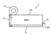
- FIG. 6 is an explanatory diagram illustrating a cooling structure of the battery cooling system according to the second embodiment.
- the second embodiment with respect to the battery pack 1 having the cold storage unit 6 integrally provided on the lower surface of the case 2 housing the battery 3, a part of the cold storage unit 6 is inside the cooling air duct 8 from the front air conditioner 23. It is the structure exposed to.
- FIG. 7 is a schematic explanatory diagram of an air conditioning system of the battery cooling system according to the second embodiment.
- the system of the front air conditioner 23 sends the high-pressure refrigerant compressed by the electric compressor 102 to the condenser 101 to cool and dissipate the heat, liquefies the refrigerant, then removes moisture and dust in the liquid tank 103 and sends the liquefied refrigerant to the solenoid valve 81.
- the refrigerant flow rate of the refrigerant line 201 toward the air conditioning evaporator 106 is controlled.
- the refrigerant is expanded to a low pressure by a valve (not shown), the refrigerant is evaporated by the air conditioning evaporator 106, the air sent to the passenger compartment by the fan 104 is cooled, and the evaporated low-pressure refrigerant is collected by the refrigerant line 202 to be recovered from the electric compressor 102. It is circulated as if it is sent to.
- FIG. 8 is a schematic explanatory diagram of the internal unit 9 of the battery cooling system according to the second embodiment.
- the duct 8 is connected to a portion where the air flow generated by the fan 104 is distributed to the center ventilator, the foot side, or the like in the space of the internal unit 9 after passing through the air conditioning evaporator 106.
- a part of the cooling air passes through the duct 8 to form a passage structure that cools the cold storage unit 6 of the battery pack 1. Since other configurations are the same as those of the first embodiment, description thereof is omitted.
- the cooling air after passing through the air conditioning evaporator 106 is taken out from the internal unit 9 by the duct 8 in the front air conditioner 23. And the cool storage part 6 is exposed to the inside through which the cooling air of the duct 8 passes.
- the front air conditioner 23 is almost always used by a driver who drives the vehicle, and the front air conditioner 23 is surely used by the driver when the environment of the vehicle is under hot weather.
- the cooling air taken out by the duct 8 becomes low temperature by the air conditioning evaporator 106. Therefore, the cool storage unit 6 is sufficiently cooled during traveling.
- the battery 3 is cooled by the cool storage unit 6 sufficiently cooled by the cooling air of the front air conditioner 23.
- the battery pack 1 may or may not be provided with the cooling fan 4.
- the cool storage unit 6 is sufficiently cooled in advance by the cooling air of the front air conditioner 23, so that the heat that rises during the parking of the battery 3 is generated by the cool storage unit. 6 is sufficiently absorbed. Therefore, the temperature rise of the battery 3 at the time of parking is suppressed so that the battery deteriorates and does not shorten the battery life. Thereby, the battery life can be extended.
- the battery cooling system according to the second embodiment has the following effects in addition to the above (1).
- the cooling means is the duct 8 that takes in a part of the cooling air of the internal unit 9 of the front air conditioner 23 provided in the vehicle and cools the cool storage unit 6, the cooling unit uses the cooling air of the front air conditioner 23. 6 can be performed, the temperature rise of the parked battery can be suppressed, and the battery life can be extended. Since other functions and effects are the same as those of the first embodiment, description thereof is omitted.
- the battery cooling system of the third embodiment is an example in which the cool storage agent is cooled by the air-conditioner wind of the rear air conditioner.
- FIG. 9 is an explanatory diagram of an installation structure of the battery cooling system according to the third embodiment in a vehicle.
- FIG. 10 is an explanatory diagram illustrating a cooling structure of the battery cooling system according to the third embodiment.
- FIG. 11 is a schematic explanatory diagram of the internal unit 11 of the rear air conditioner of the battery cooling system according to the third embodiment.
- a part of the cold storage unit 6 is inside the cooling air duct 10 from the rear air conditioner 24. It is the structure exposed to.
- the duct 10 has a structure in which one end is connected to a part of the internal unit 11 of the rear air conditioner 24, the cooling air is taken into the interior, and after passing through the cool storage unit 6, the air is exhausted to the outside air.
- the air flow generated by the fan 107 is distributed to the foot side in the space of the internal unit 11 after passing through the air conditioning evaporator 108.
- the duct 10 is connected. A part of the cooling air of the rear air conditioner 24 passes through the duct 10 to form a passage structure that cools the cold storage unit 6 of the battery pack 1. Since other configurations are the same as those of the second embodiment, description thereof is omitted.
- the cooling air taken out from the internal unit 11 by the duct 10 cools the cold storage unit 6 with little loss. In other words, cooling is performed efficiently. Therefore, the cooling air taken out by the duct 10 becomes low temperature by the air conditioning evaporator 108. Therefore, the cool storage unit 6 is sufficiently cooled during traveling. As a result, when the temperature of the battery 3 rises significantly during traveling, the battery 3 is cooled by the cool storage unit 6 sufficiently cooled by the cooling air of the rear air conditioner 24.
- the battery pack 1 may or may not be provided with the cooling fan 4.
- the cool storage unit 6 is sufficiently cooled by the cooling air of the rear air conditioner 24 in advance, the heat that rises during the parking of the battery 3 is generated by the cool storage unit. 6 is sufficiently absorbed. Therefore, the temperature rise of the battery 3 at the time of parking is suppressed so that the battery deteriorates and does not shorten the battery life. Thereby, the battery life can be extended.
- the battery cooling system according to the third embodiment has the following effects in addition to the above (1).
- the cooling means is the duct 10 that takes in a part of the cooling air of the internal unit 11 of the rear air conditioner 24 provided in the vehicle and cools the cool storage unit 6, the cooling unit uses the cooling air of the rear air conditioner 24. 6 can be performed, the temperature rise of the parked battery can be suppressed, and the battery life can be extended. Since other functions and effects are the same as those of the second embodiment, description thereof is omitted.
- the battery cooling system according to the fourth embodiment is an example in which the heat storage agent is cooled through the cold plate by the refrigerant of the front air conditioner.
- FIG. 12 is an explanatory diagram of an installation structure of the battery cooling system according to the fourth embodiment in a vehicle.
- FIG. 13 is an explanatory diagram illustrating a cooling structure of the battery cooling system according to the fourth embodiment.
- FIG. 14 is an explanatory diagram of a cold plate of the battery cooling system according to the fourth embodiment.
- the battery pack 1 provided integrally with the cold storage unit 6 on the lower surface of the case 2 containing the battery 3 is further cold-contacted with the lower surface of the cold storage unit 6, that is, the lower surface of the battery pack 1.
- a plate 12 is provided.
- the cold plate 12 is provided with a refrigerant inlet 121 and an outlet 122 of the front air conditioner 23 at the front end, and forms a flow path through which the refrigerant passes in a U shape.
- the battery pack 1 may or may not be provided with the cooling fan 4.
- FIG. 15 is a schematic explanatory diagram of an air conditioner system according to a fourth embodiment.
- the system of the front air conditioner 23 according to the fourth embodiment is provided with a refrigerant line 201 that goes from the electromagnetic valve 81 to the air conditioning evaporator 106 and a refrigerant line 203 that sends the refrigerant to the cold plate 12.
- the refrigerant discharged from the outlet 122 of the cold plate 12 is collected by the refrigerant line 204.
- the refrigerant line 204 joins the refrigerant line 202 from the air conditioning evaporator 106 to the electric compressor 102. Since other configurations are the same as those of the first embodiment, description thereof is omitted.
- the cool storage unit 6 is sufficiently cooled by the heat transfer of the cold plate 12 cooled by the refrigerant, and the cool storage unit 6 cools the battery 3. Further, even in the case of standing in the sun when parked, since the cold storage unit 6 is sufficiently cooled by the cold plate 12 in advance, the heat that rises during the parking of the battery 3 is sufficient for the cold storage unit 6. Endothermic. Therefore, the temperature rise of the battery 3 at the time of parking is suppressed so that the battery deteriorates and does not shorten the battery life. Thereby, the battery life can be extended.
- the battery cooling system according to the fourth embodiment has the following effects in addition to the above (1).
- the cooling means brings a part of the plate surface into contact with the cool storage unit 6 and passes a part of the refrigerant of the front air conditioner 23 provided in the vehicle into the plate to cool the cool storage unit 6 by heat transfer. Since it is the cold plate 12, the cold storage unit 6 can be sufficiently cooled by the cold plate 12 sufficiently cooled by the refrigerant, the temperature rise of the parked battery can be suppressed, and the battery life can be extended. can do. Since other functions and effects are the same as those of the first embodiment, description thereof is omitted.
- the battery cooling system of Example 5 is an example in which the heat storage agent is cooled by a refrigerant of a front air conditioner via a cold pipe.
- FIG. 16 is an explanatory diagram of a cold plate of the battery cooling system according to the fifth embodiment.
- the battery pack 1 provided with the cold storage unit 6 integrally on the lower surface of the case 2 housing the battery 3 is further cold-contacted so as to be in contact with the lower surface of the cold storage unit 6, that is, the lower surface of the battery pack 1.
- a pipe 13 is provided.
- the cold pipe 13 has one end of a U-shaped tube 130 having a U shape as an inlet 131 and the other end as an outlet 132.
- the cold pipe 13 is in contact with the lower surface of the regenerator 6 inside the U shape.
- a hot plate 133 is provided.
- the refrigerant line 203 is connected to the inlet 131 of the U-shaped tube 130, and the refrigerant line 204 is connected to the outlet 132 of the pipe.
- the battery pack 1 may or may not be provided with the cooling fan 4. Since other configurations are the same as those of the fourth embodiment, the description thereof is omitted.
- the battery cooling system according to the fifth embodiment has the following effects in addition to the above (1).
- the cooling means is provided in the vehicle on the cold pipe 13 including the heat transfer plate 133 that makes a part of the cool storage unit 6 contact and the U-shaped tube 130 that is arranged around the heat transfer plate 133 in a U shape. Since a part of the refrigerant of the front air conditioner 23 is passed through the U-shaped tube 130 and the cool storage unit 6 is cooled by heat transfer, the cool storage unit 6 is connected by the cold pipe 13 sufficiently cooled by the coolant. The battery can be sufficiently cooled, temperature rise of the parked battery can be suppressed, and the battery life can be extended. Since other functions and effects are the same as those of the fourth embodiment, description thereof is omitted.
- the battery cooling system according to the sixth embodiment is an example in which the heat storage agent is cooled by the refrigerant of the rear air conditioner via the cold plate.
- FIG. 17 is an explanatory diagram of an installation structure of the battery cooling system according to the sixth embodiment on a vehicle.
- FIG. 18 is an explanatory diagram illustrating a cooling structure of the battery cooling system according to the sixth embodiment.
- the battery pack 1 provided integrally with the cold storage unit 6 on the lower surface of the case 2 containing the battery 3 is further cold-contacted to the lower surface of the cold storage unit 6, that is, the lower surface of the battery pack 1.
- a plate 12 is provided.
- FIG. 19 is a schematic explanatory diagram of an air conditioner system according to a sixth embodiment.
- the rear air conditioner 24 system of the sixth embodiment is provided with a refrigerant line 201 from the electromagnetic valve 81 to the air conditioner evaporator 106 for the front air conditioner and a refrigerant line 203 to the air conditioner evaporator 108 for the rear air conditioner. Then, the refrigerant line 203 is further diverted to form the refrigerant line 205 and connected to the intake port 121 of the cold plate 12.
- the refrigerant discharged from the outlet 122 of the cold plate 12 is collected by the refrigerant line 206 and joined to the refrigerant line 204 for collecting the refrigerant discharged from the air conditioning evaporator 108 for the rear air conditioner. Is recovered by being merged into the refrigerant line 202. Then, it is sent to the electric compressor 102. Since other configurations are the same as those of the fourth embodiment, description thereof is omitted.
- the vehicle When the refrigerant of the rear air conditioner 24 is used for the cold plate 12, the vehicle includes both the front air conditioner 23 and the rear air conditioner 24. Therefore, the frequency with which the electric compressor 102 operates increases. Therefore, even if no special control is performed, the cold plate 12 has an appropriate cooling opportunity. Therefore, the cool storage unit 6 is sufficiently cooled. Further, as heat storage control, when neither the front air conditioner 23 nor the rear air conditioner 24 is driven for a long time, the electric compressor 102 may be driven at an appropriate time interval. Since other operations are the same as those of the fourth embodiment, description thereof is omitted.
- the battery cooling system according to the sixth embodiment has the following effects in addition to the above (1).
- the cooling means brings a part of the plate surface into contact with the cold storage unit 6 and passes a part of the refrigerant of the rear air conditioner 24 provided in the vehicle into the plate to cool the cold storage unit 6 by heat transfer. Since it is a cold plate, the cold storage unit 6 can be sufficiently cooled by the cold plate 12 sufficiently cooled by the refrigerant, the temperature rise of the parked battery can be suppressed, and the battery life can be extended. be able to. Since other functions and effects are the same as those of the fourth embodiment, description thereof is omitted.
- the battery cooling system of Example 7 is an example in which the heat storage agent is cooled by a refrigerant of a rear air conditioner via a cold pipe.
- the battery pack 1 provided integrally with the cold storage unit 6 on the lower surface of the case 2 housing the battery 3 is further cold-contacted with the lower surface of the cold storage unit 6, that is, the lower surface of the battery pack 1.
- a pipe 13 is provided. Since other configurations are the same as those of the sixth embodiment, description thereof is omitted.
- the battery cooling system according to the seventh embodiment has the following effects in addition to the above (1).
- the cooling means is provided in the vehicle on the cold pipe 13 including the heat transfer plate 133 that makes a part of the cool storage unit 6 contact and the U-shaped tube 130 that is arranged around the heat transfer plate 133 in a U shape. Since a part of the refrigerant of the rear air conditioner 24 is passed through the U-shaped tube 130 and the cool storage unit 6 is cooled by heat transfer, the cool storage unit 6 is connected by the cold pipe 13 sufficiently cooled by the coolant. The battery can be sufficiently cooled, temperature rise of the parked battery can be suppressed, and the battery life can be extended. Since other functions and effects are the same as those of the sixth embodiment, description thereof is omitted.
- the battery cooling system of the present invention has been described based on the first to seventh embodiments.
- the specific configuration is not limited to these embodiments, and the claims relate to each claim. Design changes and additions are allowed without departing from the scope of the invention.
Abstract
L'invention porte sur un système de refroidissement de batterie qui permet de supprimer des élévations de température d'une batterie durant des opérations en stationnement, et permet d'allonger la durée de vie de la batterie. Le système de refroidissement de batterie comprend un boîtier (2) qui contient une batterie (3) qui est chargée et déchargée, une partie de stockage de refroidissement (6) destinée à un stockage thermique et qui est formée d'une seule pièce avec le boîtier (2) sur l'intérieur de la surface de paroi de celui-ci, et un ventilateur de refroidissement (4) et une partie de passage de refroidissement (5) pour refroidir la partie de stockage de refroidissement (6). Des moyens de refroidissement comportent le ventilateur de refroidissement (4) permettant d'envoyer de l'air de refroidissement vers la batterie (3) et la partie de passage de refroidissement (5) pour distribuer une partie de l'air retenue pour la batterie (3) vers la partie de stockage de refroidissement (6).
Applications Claiming Priority (2)
| Application Number | Priority Date | Filing Date | Title |
|---|---|---|---|
| JP2008-033938 | 2008-02-15 | ||
| JP2008033938A JP2009193832A (ja) | 2008-02-15 | 2008-02-15 | バッテリ冷却システム |
Publications (1)
| Publication Number | Publication Date |
|---|---|
| WO2009102014A1 true WO2009102014A1 (fr) | 2009-08-20 |
Family
ID=40957045
Family Applications (1)
| Application Number | Title | Priority Date | Filing Date |
|---|---|---|---|
| PCT/JP2009/052404 WO2009102014A1 (fr) | 2008-02-15 | 2009-02-13 | Système de refroidissement de batterie |
Country Status (2)
| Country | Link |
|---|---|
| JP (1) | JP2009193832A (fr) |
| WO (1) | WO2009102014A1 (fr) |
Cited By (4)
| Publication number | Priority date | Publication date | Assignee | Title |
|---|---|---|---|---|
| WO2011064956A1 (fr) * | 2009-11-25 | 2011-06-03 | パナソニック株式会社 | Module de batterie |
| WO2012013582A1 (fr) * | 2010-07-30 | 2012-02-02 | Valeo Klimasysteme Gmbh | Dispositif de refroidissement pour batterie de véhicule et batterie de véhicule doté dudit dispositif de refroidissement |
| JP2012248363A (ja) * | 2011-05-26 | 2012-12-13 | Jfe Engineering Corp | 電池システム及び電気自動車 |
| US20180236892A1 (en) * | 2017-02-20 | 2018-08-23 | Hyundai Motor Company | System and method for controlling charging of plug-in vehicle |
Families Citing this family (5)
| Publication number | Priority date | Publication date | Assignee | Title |
|---|---|---|---|---|
| JP2011178321A (ja) | 2010-03-02 | 2011-09-15 | Toyota Industries Corp | 車両用空調システム |
| JP5978214B2 (ja) * | 2010-09-02 | 2016-08-24 | アカソル・ゲゼルシャフト・ミット・ベシュレンクテル・ハフツング | 冷却モジュールおよび冷却モジュールの製造方法 |
| JP5861623B2 (ja) * | 2012-11-30 | 2016-02-16 | トヨタ自動車株式会社 | 温度調節システム |
| JP6131897B2 (ja) * | 2014-03-28 | 2017-05-24 | トヨタ自動車株式会社 | 電池装置 |
| JP2018065447A (ja) * | 2016-10-19 | 2018-04-26 | 矢崎総業株式会社 | 車載システム |
Citations (5)
| Publication number | Priority date | Publication date | Assignee | Title |
|---|---|---|---|---|
| JPH10144361A (ja) * | 1996-11-12 | 1998-05-29 | Furukawa Electric Co Ltd:The | バッテリーシステムとそれを備えた輸送機械 |
| JP2001236145A (ja) * | 2000-02-22 | 2001-08-31 | Hitachi Ltd | バッテリー及びバッテリーチャージャ兼冷却装置 |
| JP2002291670A (ja) * | 2001-03-30 | 2002-10-08 | Toshiba Corp | 電池掃除機及び電池パック |
| JP2006120334A (ja) * | 2004-10-19 | 2006-05-11 | Toyota Motor Corp | バッテリ温度管理装置およびそれを備える自動車 |
| JP2006213210A (ja) * | 2005-02-04 | 2006-08-17 | Valeo Thermal Systems Japan Corp | 車載用バッテリ冷却装置 |
Family Cites Families (8)
| Publication number | Priority date | Publication date | Assignee | Title |
|---|---|---|---|---|
| JPH05344606A (ja) * | 1992-06-04 | 1993-12-24 | Seiko Epson Corp | 電気自動車の冷却システム |
| JP3458239B2 (ja) * | 1993-06-17 | 2003-10-20 | 三菱アルミニウム株式会社 | 車載用バッテリーケース |
| JP4252172B2 (ja) * | 1999-10-12 | 2009-04-08 | 株式会社日本自動車部品総合研究所 | バッテリ冷却装置 |
| JP2002354608A (ja) * | 2001-05-28 | 2002-12-06 | Honda Motor Co Ltd | 電気自動車のバッテリ冷却装置 |
| IL144832A (en) * | 2001-08-09 | 2005-06-19 | Polyrit | Thermal jacket for battery |
| JP3969254B2 (ja) * | 2001-10-29 | 2007-09-05 | 株式会社デンソー | バッテリ温度管理装置 |
| JP4285405B2 (ja) * | 2004-12-17 | 2009-06-24 | 日産自動車株式会社 | ハイブリッド自動車 |
| WO2008018374A1 (fr) * | 2006-08-11 | 2008-02-14 | Calsonic Kansei Corporation | Système de refroidissement de batterie d'automobile |
-
2008
- 2008-02-15 JP JP2008033938A patent/JP2009193832A/ja active Pending
-
2009
- 2009-02-13 WO PCT/JP2009/052404 patent/WO2009102014A1/fr active Application Filing
Patent Citations (5)
| Publication number | Priority date | Publication date | Assignee | Title |
|---|---|---|---|---|
| JPH10144361A (ja) * | 1996-11-12 | 1998-05-29 | Furukawa Electric Co Ltd:The | バッテリーシステムとそれを備えた輸送機械 |
| JP2001236145A (ja) * | 2000-02-22 | 2001-08-31 | Hitachi Ltd | バッテリー及びバッテリーチャージャ兼冷却装置 |
| JP2002291670A (ja) * | 2001-03-30 | 2002-10-08 | Toshiba Corp | 電池掃除機及び電池パック |
| JP2006120334A (ja) * | 2004-10-19 | 2006-05-11 | Toyota Motor Corp | バッテリ温度管理装置およびそれを備える自動車 |
| JP2006213210A (ja) * | 2005-02-04 | 2006-08-17 | Valeo Thermal Systems Japan Corp | 車載用バッテリ冷却装置 |
Cited By (7)
| Publication number | Priority date | Publication date | Assignee | Title |
|---|---|---|---|---|
| WO2011064956A1 (fr) * | 2009-11-25 | 2011-06-03 | パナソニック株式会社 | Module de batterie |
| JP4814405B2 (ja) * | 2009-11-25 | 2011-11-16 | パナソニック株式会社 | 電池モジュール |
| WO2012013582A1 (fr) * | 2010-07-30 | 2012-02-02 | Valeo Klimasysteme Gmbh | Dispositif de refroidissement pour batterie de véhicule et batterie de véhicule doté dudit dispositif de refroidissement |
| CN103155264A (zh) * | 2010-07-30 | 2013-06-12 | 法雷奥空调系统有限责任公司 | 用于车辆电池的冷却装置和具有这样的冷却装置的车辆电池 |
| JP2012248363A (ja) * | 2011-05-26 | 2012-12-13 | Jfe Engineering Corp | 電池システム及び電気自動車 |
| US20180236892A1 (en) * | 2017-02-20 | 2018-08-23 | Hyundai Motor Company | System and method for controlling charging of plug-in vehicle |
| US11135926B2 (en) * | 2017-02-20 | 2021-10-05 | Hyundai Motor Company | System and method for controlling charging of plug-in vehicle |
Also Published As
| Publication number | Publication date |
|---|---|
| JP2009193832A (ja) | 2009-08-27 |
Similar Documents
| Publication | Publication Date | Title |
|---|---|---|
| WO2009102014A1 (fr) | Système de refroidissement de batterie | |
| CN107031347B (zh) | 车载空调装置 | |
| JP2008054379A (ja) | 車両用バッテリ冷却システム | |
| US9796241B2 (en) | Vehicle temperature control apparatus and in-vehicle thermal system | |
| JP6192434B2 (ja) | 車両用空気調和装置 | |
| EP2392486B2 (fr) | Système de gestion thermique avec boucles de refroidissement à double mode | |
| KR101448656B1 (ko) | 전기자동차용 공기조화장치 | |
| WO2013132756A1 (fr) | Dispositif de régulation de température | |
| US9555691B2 (en) | Climate-control device and method for its operation | |
| JP2007069733A (ja) | 車両用空調装置を利用した発熱体冷却システム | |
| WO2008018374A1 (fr) | Système de refroidissement de batterie d'automobile | |
| JP6150113B2 (ja) | 車両熱管理システム | |
| CN105637699A (zh) | 蓄电池调温装置 | |
| JP4930310B2 (ja) | 電気自動車 | |
| WO2020153032A1 (fr) | Dispositif de réglage de température de batterie de véhicule, et dispositif de climatisation de véhicule le comportant | |
| JP2012156010A (ja) | 電池冷却構造 | |
| JP2013180614A (ja) | 車両用電池温度制御構造 | |
| JP2010280288A (ja) | 蓄電装置の冷却装置 | |
| JP2017149324A (ja) | 車両用空調装置 | |
| JP7263116B2 (ja) | 車両搭載機器の温度調整装置及びそれを備えた車両用空気調和装置 | |
| CN111051096B (zh) | 车辆用空气调节装置 | |
| KR101858692B1 (ko) | 전기자동차 | |
| JP4887621B2 (ja) | 充放電制御装置および車両 | |
| JP2008044476A (ja) | 車両用バッテリ冷却システム | |
| JP2006218920A (ja) | 車両用空調制御装置 |
Legal Events
| Date | Code | Title | Description |
|---|---|---|---|
| 121 | Ep: the epo has been informed by wipo that ep was designated in this application |
Ref document number: 09710584 Country of ref document: EP Kind code of ref document: A1 |
|
| NENP | Non-entry into the national phase |
Ref country code: DE |
|
| 122 | Ep: pct application non-entry in european phase |
Ref document number: 09710584 Country of ref document: EP Kind code of ref document: A1 |