WO2009102014A1 - Battery cooling system - Google Patents
Battery cooling system Download PDFInfo
- Publication number
- WO2009102014A1 WO2009102014A1 PCT/JP2009/052404 JP2009052404W WO2009102014A1 WO 2009102014 A1 WO2009102014 A1 WO 2009102014A1 JP 2009052404 W JP2009052404 W JP 2009052404W WO 2009102014 A1 WO2009102014 A1 WO 2009102014A1
- Authority
- WO
- WIPO (PCT)
- Prior art keywords
- battery
- cooling
- cooling system
- air conditioner
- refrigerant
- Prior art date
Links
Images


Classifications
-
- H—ELECTRICITY
- H01—ELECTRIC ELEMENTS
- H01M—PROCESSES OR MEANS, e.g. BATTERIES, FOR THE DIRECT CONVERSION OF CHEMICAL ENERGY INTO ELECTRICAL ENERGY
- H01M50/00—Constructional details or processes of manufacture of the non-active parts of electrochemical cells other than fuel cells, e.g. hybrid cells
- H01M50/20—Mountings; Secondary casings or frames; Racks, modules or packs; Suspension devices; Shock absorbers; Transport or carrying devices; Holders
- H01M50/202—Casings or frames around the primary casing of a single cell or a single battery
-
- B—PERFORMING OPERATIONS; TRANSPORTING
- B60—VEHICLES IN GENERAL
- B60H—ARRANGEMENTS OF HEATING, COOLING, VENTILATING OR OTHER AIR-TREATING DEVICES SPECIALLY ADAPTED FOR PASSENGER OR GOODS SPACES OF VEHICLES
- B60H1/00—Heating, cooling or ventilating [HVAC] devices
- B60H1/00271—HVAC devices specially adapted for particular vehicle parts or components and being connected to the vehicle HVAC unit
- B60H1/00278—HVAC devices specially adapted for particular vehicle parts or components and being connected to the vehicle HVAC unit for the battery
-
- B—PERFORMING OPERATIONS; TRANSPORTING
- B60—VEHICLES IN GENERAL
- B60L—PROPULSION OF ELECTRICALLY-PROPELLED VEHICLES; SUPPLYING ELECTRIC POWER FOR AUXILIARY EQUIPMENT OF ELECTRICALLY-PROPELLED VEHICLES; ELECTRODYNAMIC BRAKE SYSTEMS FOR VEHICLES IN GENERAL; MAGNETIC SUSPENSION OR LEVITATION FOR VEHICLES; MONITORING OPERATING VARIABLES OF ELECTRICALLY-PROPELLED VEHICLES; ELECTRIC SAFETY DEVICES FOR ELECTRICALLY-PROPELLED VEHICLES
- B60L1/00—Supplying electric power to auxiliary equipment of vehicles
- B60L1/02—Supplying electric power to auxiliary equipment of vehicles to electric heating circuits
-
- B—PERFORMING OPERATIONS; TRANSPORTING
- B60—VEHICLES IN GENERAL
- B60L—PROPULSION OF ELECTRICALLY-PROPELLED VEHICLES; SUPPLYING ELECTRIC POWER FOR AUXILIARY EQUIPMENT OF ELECTRICALLY-PROPELLED VEHICLES; ELECTRODYNAMIC BRAKE SYSTEMS FOR VEHICLES IN GENERAL; MAGNETIC SUSPENSION OR LEVITATION FOR VEHICLES; MONITORING OPERATING VARIABLES OF ELECTRICALLY-PROPELLED VEHICLES; ELECTRIC SAFETY DEVICES FOR ELECTRICALLY-PROPELLED VEHICLES
- B60L50/00—Electric propulsion with power supplied within the vehicle
- B60L50/50—Electric propulsion with power supplied within the vehicle using propulsion power supplied by batteries or fuel cells
- B60L50/60—Electric propulsion with power supplied within the vehicle using propulsion power supplied by batteries or fuel cells using power supplied by batteries
- B60L50/64—Constructional details of batteries specially adapted for electric vehicles
-
- B—PERFORMING OPERATIONS; TRANSPORTING
- B60—VEHICLES IN GENERAL
- B60L—PROPULSION OF ELECTRICALLY-PROPELLED VEHICLES; SUPPLYING ELECTRIC POWER FOR AUXILIARY EQUIPMENT OF ELECTRICALLY-PROPELLED VEHICLES; ELECTRODYNAMIC BRAKE SYSTEMS FOR VEHICLES IN GENERAL; MAGNETIC SUSPENSION OR LEVITATION FOR VEHICLES; MONITORING OPERATING VARIABLES OF ELECTRICALLY-PROPELLED VEHICLES; ELECTRIC SAFETY DEVICES FOR ELECTRICALLY-PROPELLED VEHICLES
- B60L58/00—Methods or circuit arrangements for monitoring or controlling batteries or fuel cells, specially adapted for electric vehicles
- B60L58/10—Methods or circuit arrangements for monitoring or controlling batteries or fuel cells, specially adapted for electric vehicles for monitoring or controlling batteries
- B60L58/24—Methods or circuit arrangements for monitoring or controlling batteries or fuel cells, specially adapted for electric vehicles for monitoring or controlling batteries for controlling the temperature of batteries
- B60L58/26—Methods or circuit arrangements for monitoring or controlling batteries or fuel cells, specially adapted for electric vehicles for monitoring or controlling batteries for controlling the temperature of batteries by cooling
-
- H—ELECTRICITY
- H01—ELECTRIC ELEMENTS
- H01M—PROCESSES OR MEANS, e.g. BATTERIES, FOR THE DIRECT CONVERSION OF CHEMICAL ENERGY INTO ELECTRICAL ENERGY
- H01M10/00—Secondary cells; Manufacture thereof
- H01M10/60—Heating or cooling; Temperature control
- H01M10/61—Types of temperature control
- H01M10/613—Cooling or keeping cold
-
- H—ELECTRICITY
- H01—ELECTRIC ELEMENTS
- H01M—PROCESSES OR MEANS, e.g. BATTERIES, FOR THE DIRECT CONVERSION OF CHEMICAL ENERGY INTO ELECTRICAL ENERGY
- H01M10/00—Secondary cells; Manufacture thereof
- H01M10/60—Heating or cooling; Temperature control
- H01M10/62—Heating or cooling; Temperature control specially adapted for specific applications
- H01M10/625—Vehicles
-
- H—ELECTRICITY
- H01—ELECTRIC ELEMENTS
- H01M—PROCESSES OR MEANS, e.g. BATTERIES, FOR THE DIRECT CONVERSION OF CHEMICAL ENERGY INTO ELECTRICAL ENERGY
- H01M10/00—Secondary cells; Manufacture thereof
- H01M10/60—Heating or cooling; Temperature control
- H01M10/65—Means for temperature control structurally associated with the cells
- H01M10/655—Solid structures for heat exchange or heat conduction
- H01M10/6556—Solid parts with flow channel passages or pipes for heat exchange
-
- H—ELECTRICITY
- H01—ELECTRIC ELEMENTS
- H01M—PROCESSES OR MEANS, e.g. BATTERIES, FOR THE DIRECT CONVERSION OF CHEMICAL ENERGY INTO ELECTRICAL ENERGY
- H01M10/00—Secondary cells; Manufacture thereof
- H01M10/60—Heating or cooling; Temperature control
- H01M10/65—Means for temperature control structurally associated with the cells
- H01M10/656—Means for temperature control structurally associated with the cells characterised by the type of heat-exchange fluid
- H01M10/6561—Gases
- H01M10/6563—Gases with forced flow, e.g. by blowers
-
- H—ELECTRICITY
- H01—ELECTRIC ELEMENTS
- H01M—PROCESSES OR MEANS, e.g. BATTERIES, FOR THE DIRECT CONVERSION OF CHEMICAL ENERGY INTO ELECTRICAL ENERGY
- H01M10/00—Secondary cells; Manufacture thereof
- H01M10/60—Heating or cooling; Temperature control
- H01M10/65—Means for temperature control structurally associated with the cells
- H01M10/656—Means for temperature control structurally associated with the cells characterised by the type of heat-exchange fluid
- H01M10/6561—Gases
- H01M10/6566—Means within the gas flow to guide the flow around one or more cells, e.g. manifolds, baffles or other barriers
-
- H—ELECTRICITY
- H01—ELECTRIC ELEMENTS
- H01M—PROCESSES OR MEANS, e.g. BATTERIES, FOR THE DIRECT CONVERSION OF CHEMICAL ENERGY INTO ELECTRICAL ENERGY
- H01M50/00—Constructional details or processes of manufacture of the non-active parts of electrochemical cells other than fuel cells, e.g. hybrid cells
- H01M50/20—Mountings; Secondary casings or frames; Racks, modules or packs; Suspension devices; Shock absorbers; Transport or carrying devices; Holders
- H01M50/249—Mountings; Secondary casings or frames; Racks, modules or packs; Suspension devices; Shock absorbers; Transport or carrying devices; Holders specially adapted for aircraft or vehicles, e.g. cars or trains
-
- B—PERFORMING OPERATIONS; TRANSPORTING
- B60—VEHICLES IN GENERAL
- B60H—ARRANGEMENTS OF HEATING, COOLING, VENTILATING OR OTHER AIR-TREATING DEVICES SPECIALLY ADAPTED FOR PASSENGER OR GOODS SPACES OF VEHICLES
- B60H1/00—Heating, cooling or ventilating [HVAC] devices
- B60H1/00271—HVAC devices specially adapted for particular vehicle parts or components and being connected to the vehicle HVAC unit
- B60H2001/003—Component temperature regulation using an air flow
-
- B—PERFORMING OPERATIONS; TRANSPORTING
- B60—VEHICLES IN GENERAL
- B60L—PROPULSION OF ELECTRICALLY-PROPELLED VEHICLES; SUPPLYING ELECTRIC POWER FOR AUXILIARY EQUIPMENT OF ELECTRICALLY-PROPELLED VEHICLES; ELECTRODYNAMIC BRAKE SYSTEMS FOR VEHICLES IN GENERAL; MAGNETIC SUSPENSION OR LEVITATION FOR VEHICLES; MONITORING OPERATING VARIABLES OF ELECTRICALLY-PROPELLED VEHICLES; ELECTRIC SAFETY DEVICES FOR ELECTRICALLY-PROPELLED VEHICLES
- B60L2240/00—Control parameters of input or output; Target parameters
- B60L2240/40—Drive Train control parameters
- B60L2240/54—Drive Train control parameters related to batteries
- B60L2240/545—Temperature
-
- Y—GENERAL TAGGING OF NEW TECHNOLOGICAL DEVELOPMENTS; GENERAL TAGGING OF CROSS-SECTIONAL TECHNOLOGIES SPANNING OVER SEVERAL SECTIONS OF THE IPC; TECHNICAL SUBJECTS COVERED BY FORMER USPC CROSS-REFERENCE ART COLLECTIONS [XRACs] AND DIGESTS
- Y02—TECHNOLOGIES OR APPLICATIONS FOR MITIGATION OR ADAPTATION AGAINST CLIMATE CHANGE
- Y02E—REDUCTION OF GREENHOUSE GAS [GHG] EMISSIONS, RELATED TO ENERGY GENERATION, TRANSMISSION OR DISTRIBUTION
- Y02E60/00—Enabling technologies; Technologies with a potential or indirect contribution to GHG emissions mitigation
- Y02E60/10—Energy storage using batteries
-
- Y—GENERAL TAGGING OF NEW TECHNOLOGICAL DEVELOPMENTS; GENERAL TAGGING OF CROSS-SECTIONAL TECHNOLOGIES SPANNING OVER SEVERAL SECTIONS OF THE IPC; TECHNICAL SUBJECTS COVERED BY FORMER USPC CROSS-REFERENCE ART COLLECTIONS [XRACs] AND DIGESTS
- Y02—TECHNOLOGIES OR APPLICATIONS FOR MITIGATION OR ADAPTATION AGAINST CLIMATE CHANGE
- Y02T—CLIMATE CHANGE MITIGATION TECHNOLOGIES RELATED TO TRANSPORTATION
- Y02T10/00—Road transport of goods or passengers
- Y02T10/60—Other road transportation technologies with climate change mitigation effect
- Y02T10/70—Energy storage systems for electromobility, e.g. batteries
Definitions
- the present invention belongs to the technical field of a battery cooling system installed in a vehicle and used for driving the vehicle.
- Patent Document 1 Japanese Patent No. 32409773 (page 1-13, all figures)
- the present invention has been made paying attention to the above-described problems, and the object of the present invention is to provide a battery cooling system that can suppress the temperature rise of a parked battery and can extend the life of the battery. It is to provide.
- a case in which a battery for charging / discharging is housed a heat storage means that is integrally provided inside the wall surface of the case and stores heat, and cooling that cools the heat storage means Means.
- the temperature rise of the parked battery can be suppressed, and the battery life can be extended.
- FIG. It is explanatory drawing which shows the vehicle installation position of the battery cooling system of Example 1.
- FIG. It is a structure explanatory drawing of the battery pack of the battery cooling system of Example 1.
- FIG. It is a structure explanatory sectional view of the battery pack of the battery cooling system of Example 1. It is a figure which shows the outline of the block structure regarding cooling of the battery cooling system of Example 1.
- FIG. It is explanatory drawing of the installation structure to the vehicle of the battery cooling system of Example 2.
- FIG. It is explanatory drawing which shows the cooling structure of the battery cooling system of Example 2.
- FIG. 10 is an explanatory diagram illustrating a cooling structure of a battery cooling system according to a sixth embodiment. It is explanatory drawing of the outline of the air conditioning system of Example 6.
- FIG. 10 is an explanatory diagram illustrating a cooling structure of a battery cooling system according to a sixth embodiment. It is explanatory drawing of the outline of the air conditioning system of Example 6.
- FIG. 1 is an explanatory diagram illustrating a vehicle installation position of the battery cooling system according to the first embodiment.
- FIG. 2 is an explanatory diagram of the structure of the battery pack of the battery cooling system according to the first embodiment.
- FIG. 3 is a cross-sectional view illustrating the structure of the battery pack of the battery cooling system according to the first embodiment.
- the battery pack 1 includes a case 2, a battery 3, a cooling fan 4, a cooling passage unit 5, and a cold storage unit 6.
- the case 2 is a structural member that protects the battery 3 and installs the battery pack 1 in the vehicle.
- the battery 3 is a lithium ion battery that performs charge and discharge by exchanging lithium ions between electrodes. Lithium-ion batteries have the advantageous feature that no so-called memory effect occurs.
- the battery 3 used for running the vehicle is an assembled battery in which a plurality of lithium ion batteries are combined in parallel or in series.
- JP-A-2000-116427 is cited as a detailed example of the battery pack for traveling.
- the structure of the assembled battery is not limited to this detailed example, but a plurality of the minimum units in which plate-like lithium ion batteries are combined are used. The total number reaches several dozen.
- the battery pack 1 has a structure in which plate-shaped batteries 3 are arranged on the left and right sides in the case 2 so that the longitudinal direction of the vehicle is the longitudinal direction. Then, cooling air is introduced into the inside of the case 2 from the cooling passage portion 5 installed on the front side of the case 2, and is discharged to the outside of the case 2 from the discharge port 21 provided at the rear portion of the case 2. At this time, inside the case 2, as shown in FIG. 3, a part of the support portion above and to the left and right sides of the battery 3 and below the battery 3 serves as a cooling air passage 22.
- the cold storage unit 6 of the first embodiment is integrally provided below the case 2, and as shown in FIG. 3, the cold storage agents 61 are arranged on the left and right sides of the vehicle front-rear direction, respectively. A long space is provided in the direction, and this is used as a cooling air passage 62. Then, cooling air is introduced into the passage 62 inside the cold storage unit 6 from the cooling passage unit 5 installed on the front side of the case 2 and the cold storage unit 6, and is discharged from the discharge port 63.
- the cold storage agent 61 is made of nitric acid / ammonium chloride, polypropylene glycol, a water-absorbing polymer, vegetable cellulose, or the like.
- the cooling fan 4 is installed in the upper part of the case 2, and the fan is electrically driven by the control of the battery controller 7 to blow air to the cooling passage portion 5.
- a blower fan that blows air by rotating a cylindrical object is mentioned.
- the cooling passage portion 5 is a front portion of the case 2 and the cold storage portion 6 and is a passage for sending the air blown from the cooling fan 4 to the passage 22 of the case 2 and the passage 62 of the cold storage portion 6.
- FIG. 4 is a schematic diagram illustrating a block configuration related to cooling of the battery cooling system according to the first embodiment.
- the battery pack 1 includes temperature sensors 71 and 72 that detect the temperature of each battery 3 and an SOC sensor 73 that detects the charging rate of the battery 3.
- the detection results of the temperature sensors 71 and 72 and the SOC sensor 73 are input to the battery controller 7.
- the battery controller 7 drives the cooling fan 4 to blow air. Further, the air may be blown even when a predetermined condition is satisfied.
- the temperature sensors 71 and 72 detect the temperature of the battery 3 in the battery pack 1 during traveling. Then, when the battery temperature becomes equal to or higher than a predetermined temperature due to repeated charge and discharge of the battery during traveling, the cooling fan 4 is driven under the control of the battery controller 7 so that the temperature of the battery 3 becomes equal to or lower than the predetermined temperature. .
- the cooling air passes from the cooling passage portion 5 through the passage 22 inside the case 2 and is discharged from the discharge port 21 to the outside of the case 2.
- the battery 3 can output the output relating to the driving of the vehicle satisfactorily without being damaged by the temperature rise.
- the air blown from the cooling fan 4 that cools the battery 3 is distributed by the cooling passage portion 5, and a part of the air flows toward the cold storage portion 6 and passes through the passage 62 inside the cold storage portion 6.
- the agent 61 is cooled.
- the battery 3 may have a significant temperature rise due to a high load applied to the battery 3.
- the cool storage agent 61 is cooled together with the battery 3 in this way, in the case where the temperature rise of the running battery is significant, in addition to the cooling air cooling by the cooling fan 4, the cool storage unit 6 for the amount of cool storage up to that point is performed.
- the cooling from is performed from below.
- the battery temperature control by the battery controller 7 is not performed.
- the temperature of the battery 3 further increases because of the increase in the temperature of the passenger compartment caused by leaving under the sun in addition to the self-heating of the battery due to the use so far.
- the cool storage unit 6 is provided integrally with the case 2 below the battery 3 and is cooled by the cooling fan 4 in the same manner as the battery 3 during traveling. Therefore, the heat that rises while the battery 3 is parked is absorbed by the cold storage unit 6. Therefore, the temperature rise of the battery 3 at the time of parking is suppressed so that the battery deteriorates and does not shorten the battery life. Thereby, the battery life can be extended.
- the battery controller 7 basically controls the cooling fan 4 so as to lower the temperature of the battery 3 by the temperature sensors 71 and 72.
- heat storage control for driving the cooling fan 4 may be performed at a time when the cooling fan 4 is not yet at a starting temperature. Then, the cooling while the battery 3 is traveling is also coordinated with the cold storage unit 6, and the time for rotating the cooling fan 4 at a high speed can be shortened or the high-speed rotation can be avoided. Then, the cooling fan 4 is driven with low noise, and the quietness in the passenger compartment can be ensured. At that time, the temperature change of the battery 3 itself is suppressed. In other words, the cool storage unit 6 causes the battery 3 to be provided with a damper for temperature change. Then, it is less likely that the temperature of the battery is increased, which affects the life, and the life of the battery can be extended.
- Case 2 in which a battery 3 for charging / discharging is housed, a cold storage unit 6 that is integrally provided inside the wall surface of the case 2 and stores heat, a cooling fan 4 and a cooling passage for cooling the cold storage unit 6 Since the part 5 is provided, the temperature rise of the parked battery can be suppressed, and the battery life can be extended.
- the cooling means includes the cooling fan 4 that sends cooling air to the battery 3 and the cooling passage portion 5 that distributes part of the air blown to the battery 3 to the cold storage portion 6, the cooling means cools the battery 3.
- Cold storage can be performed by a part of the wind, the temperature rise of the parked battery can be suppressed, and the battery life can be extended.
- the battery cooling system of the second embodiment is an example in which the cool storage agent is cooled by the air-conditioner wind of the front air conditioner.
- FIG. 5 is an explanatory diagram of an installation structure of the battery cooling system according to the second embodiment on a vehicle.
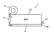
- FIG. 6 is an explanatory diagram illustrating a cooling structure of the battery cooling system according to the second embodiment.
- the second embodiment with respect to the battery pack 1 having the cold storage unit 6 integrally provided on the lower surface of the case 2 housing the battery 3, a part of the cold storage unit 6 is inside the cooling air duct 8 from the front air conditioner 23. It is the structure exposed to.
- FIG. 7 is a schematic explanatory diagram of an air conditioning system of the battery cooling system according to the second embodiment.
- the system of the front air conditioner 23 sends the high-pressure refrigerant compressed by the electric compressor 102 to the condenser 101 to cool and dissipate the heat, liquefies the refrigerant, then removes moisture and dust in the liquid tank 103 and sends the liquefied refrigerant to the solenoid valve 81.
- the refrigerant flow rate of the refrigerant line 201 toward the air conditioning evaporator 106 is controlled.
- the refrigerant is expanded to a low pressure by a valve (not shown), the refrigerant is evaporated by the air conditioning evaporator 106, the air sent to the passenger compartment by the fan 104 is cooled, and the evaporated low-pressure refrigerant is collected by the refrigerant line 202 to be recovered from the electric compressor 102. It is circulated as if it is sent to.
- FIG. 8 is a schematic explanatory diagram of the internal unit 9 of the battery cooling system according to the second embodiment.
- the duct 8 is connected to a portion where the air flow generated by the fan 104 is distributed to the center ventilator, the foot side, or the like in the space of the internal unit 9 after passing through the air conditioning evaporator 106.
- a part of the cooling air passes through the duct 8 to form a passage structure that cools the cold storage unit 6 of the battery pack 1. Since other configurations are the same as those of the first embodiment, description thereof is omitted.
- the cooling air after passing through the air conditioning evaporator 106 is taken out from the internal unit 9 by the duct 8 in the front air conditioner 23. And the cool storage part 6 is exposed to the inside through which the cooling air of the duct 8 passes.
- the front air conditioner 23 is almost always used by a driver who drives the vehicle, and the front air conditioner 23 is surely used by the driver when the environment of the vehicle is under hot weather.
- the cooling air taken out by the duct 8 becomes low temperature by the air conditioning evaporator 106. Therefore, the cool storage unit 6 is sufficiently cooled during traveling.
- the battery 3 is cooled by the cool storage unit 6 sufficiently cooled by the cooling air of the front air conditioner 23.
- the battery pack 1 may or may not be provided with the cooling fan 4.
- the cool storage unit 6 is sufficiently cooled in advance by the cooling air of the front air conditioner 23, so that the heat that rises during the parking of the battery 3 is generated by the cool storage unit. 6 is sufficiently absorbed. Therefore, the temperature rise of the battery 3 at the time of parking is suppressed so that the battery deteriorates and does not shorten the battery life. Thereby, the battery life can be extended.
- the battery cooling system according to the second embodiment has the following effects in addition to the above (1).
- the cooling means is the duct 8 that takes in a part of the cooling air of the internal unit 9 of the front air conditioner 23 provided in the vehicle and cools the cool storage unit 6, the cooling unit uses the cooling air of the front air conditioner 23. 6 can be performed, the temperature rise of the parked battery can be suppressed, and the battery life can be extended. Since other functions and effects are the same as those of the first embodiment, description thereof is omitted.
- the battery cooling system of the third embodiment is an example in which the cool storage agent is cooled by the air-conditioner wind of the rear air conditioner.
- FIG. 9 is an explanatory diagram of an installation structure of the battery cooling system according to the third embodiment in a vehicle.
- FIG. 10 is an explanatory diagram illustrating a cooling structure of the battery cooling system according to the third embodiment.
- FIG. 11 is a schematic explanatory diagram of the internal unit 11 of the rear air conditioner of the battery cooling system according to the third embodiment.
- a part of the cold storage unit 6 is inside the cooling air duct 10 from the rear air conditioner 24. It is the structure exposed to.
- the duct 10 has a structure in which one end is connected to a part of the internal unit 11 of the rear air conditioner 24, the cooling air is taken into the interior, and after passing through the cool storage unit 6, the air is exhausted to the outside air.
- the air flow generated by the fan 107 is distributed to the foot side in the space of the internal unit 11 after passing through the air conditioning evaporator 108.
- the duct 10 is connected. A part of the cooling air of the rear air conditioner 24 passes through the duct 10 to form a passage structure that cools the cold storage unit 6 of the battery pack 1. Since other configurations are the same as those of the second embodiment, description thereof is omitted.
- the cooling air taken out from the internal unit 11 by the duct 10 cools the cold storage unit 6 with little loss. In other words, cooling is performed efficiently. Therefore, the cooling air taken out by the duct 10 becomes low temperature by the air conditioning evaporator 108. Therefore, the cool storage unit 6 is sufficiently cooled during traveling. As a result, when the temperature of the battery 3 rises significantly during traveling, the battery 3 is cooled by the cool storage unit 6 sufficiently cooled by the cooling air of the rear air conditioner 24.
- the battery pack 1 may or may not be provided with the cooling fan 4.
- the cool storage unit 6 is sufficiently cooled by the cooling air of the rear air conditioner 24 in advance, the heat that rises during the parking of the battery 3 is generated by the cool storage unit. 6 is sufficiently absorbed. Therefore, the temperature rise of the battery 3 at the time of parking is suppressed so that the battery deteriorates and does not shorten the battery life. Thereby, the battery life can be extended.
- the battery cooling system according to the third embodiment has the following effects in addition to the above (1).
- the cooling means is the duct 10 that takes in a part of the cooling air of the internal unit 11 of the rear air conditioner 24 provided in the vehicle and cools the cool storage unit 6, the cooling unit uses the cooling air of the rear air conditioner 24. 6 can be performed, the temperature rise of the parked battery can be suppressed, and the battery life can be extended. Since other functions and effects are the same as those of the second embodiment, description thereof is omitted.
- the battery cooling system according to the fourth embodiment is an example in which the heat storage agent is cooled through the cold plate by the refrigerant of the front air conditioner.
- FIG. 12 is an explanatory diagram of an installation structure of the battery cooling system according to the fourth embodiment in a vehicle.
- FIG. 13 is an explanatory diagram illustrating a cooling structure of the battery cooling system according to the fourth embodiment.
- FIG. 14 is an explanatory diagram of a cold plate of the battery cooling system according to the fourth embodiment.
- the battery pack 1 provided integrally with the cold storage unit 6 on the lower surface of the case 2 containing the battery 3 is further cold-contacted with the lower surface of the cold storage unit 6, that is, the lower surface of the battery pack 1.
- a plate 12 is provided.
- the cold plate 12 is provided with a refrigerant inlet 121 and an outlet 122 of the front air conditioner 23 at the front end, and forms a flow path through which the refrigerant passes in a U shape.
- the battery pack 1 may or may not be provided with the cooling fan 4.
- FIG. 15 is a schematic explanatory diagram of an air conditioner system according to a fourth embodiment.
- the system of the front air conditioner 23 according to the fourth embodiment is provided with a refrigerant line 201 that goes from the electromagnetic valve 81 to the air conditioning evaporator 106 and a refrigerant line 203 that sends the refrigerant to the cold plate 12.
- the refrigerant discharged from the outlet 122 of the cold plate 12 is collected by the refrigerant line 204.
- the refrigerant line 204 joins the refrigerant line 202 from the air conditioning evaporator 106 to the electric compressor 102. Since other configurations are the same as those of the first embodiment, description thereof is omitted.
- the cool storage unit 6 is sufficiently cooled by the heat transfer of the cold plate 12 cooled by the refrigerant, and the cool storage unit 6 cools the battery 3. Further, even in the case of standing in the sun when parked, since the cold storage unit 6 is sufficiently cooled by the cold plate 12 in advance, the heat that rises during the parking of the battery 3 is sufficient for the cold storage unit 6. Endothermic. Therefore, the temperature rise of the battery 3 at the time of parking is suppressed so that the battery deteriorates and does not shorten the battery life. Thereby, the battery life can be extended.
- the battery cooling system according to the fourth embodiment has the following effects in addition to the above (1).
- the cooling means brings a part of the plate surface into contact with the cool storage unit 6 and passes a part of the refrigerant of the front air conditioner 23 provided in the vehicle into the plate to cool the cool storage unit 6 by heat transfer. Since it is the cold plate 12, the cold storage unit 6 can be sufficiently cooled by the cold plate 12 sufficiently cooled by the refrigerant, the temperature rise of the parked battery can be suppressed, and the battery life can be extended. can do. Since other functions and effects are the same as those of the first embodiment, description thereof is omitted.
- the battery cooling system of Example 5 is an example in which the heat storage agent is cooled by a refrigerant of a front air conditioner via a cold pipe.
- FIG. 16 is an explanatory diagram of a cold plate of the battery cooling system according to the fifth embodiment.
- the battery pack 1 provided with the cold storage unit 6 integrally on the lower surface of the case 2 housing the battery 3 is further cold-contacted so as to be in contact with the lower surface of the cold storage unit 6, that is, the lower surface of the battery pack 1.
- a pipe 13 is provided.
- the cold pipe 13 has one end of a U-shaped tube 130 having a U shape as an inlet 131 and the other end as an outlet 132.
- the cold pipe 13 is in contact with the lower surface of the regenerator 6 inside the U shape.
- a hot plate 133 is provided.
- the refrigerant line 203 is connected to the inlet 131 of the U-shaped tube 130, and the refrigerant line 204 is connected to the outlet 132 of the pipe.
- the battery pack 1 may or may not be provided with the cooling fan 4. Since other configurations are the same as those of the fourth embodiment, the description thereof is omitted.
- the battery cooling system according to the fifth embodiment has the following effects in addition to the above (1).
- the cooling means is provided in the vehicle on the cold pipe 13 including the heat transfer plate 133 that makes a part of the cool storage unit 6 contact and the U-shaped tube 130 that is arranged around the heat transfer plate 133 in a U shape. Since a part of the refrigerant of the front air conditioner 23 is passed through the U-shaped tube 130 and the cool storage unit 6 is cooled by heat transfer, the cool storage unit 6 is connected by the cold pipe 13 sufficiently cooled by the coolant. The battery can be sufficiently cooled, temperature rise of the parked battery can be suppressed, and the battery life can be extended. Since other functions and effects are the same as those of the fourth embodiment, description thereof is omitted.
- the battery cooling system according to the sixth embodiment is an example in which the heat storage agent is cooled by the refrigerant of the rear air conditioner via the cold plate.
- FIG. 17 is an explanatory diagram of an installation structure of the battery cooling system according to the sixth embodiment on a vehicle.
- FIG. 18 is an explanatory diagram illustrating a cooling structure of the battery cooling system according to the sixth embodiment.
- the battery pack 1 provided integrally with the cold storage unit 6 on the lower surface of the case 2 containing the battery 3 is further cold-contacted to the lower surface of the cold storage unit 6, that is, the lower surface of the battery pack 1.
- a plate 12 is provided.
- FIG. 19 is a schematic explanatory diagram of an air conditioner system according to a sixth embodiment.
- the rear air conditioner 24 system of the sixth embodiment is provided with a refrigerant line 201 from the electromagnetic valve 81 to the air conditioner evaporator 106 for the front air conditioner and a refrigerant line 203 to the air conditioner evaporator 108 for the rear air conditioner. Then, the refrigerant line 203 is further diverted to form the refrigerant line 205 and connected to the intake port 121 of the cold plate 12.
- the refrigerant discharged from the outlet 122 of the cold plate 12 is collected by the refrigerant line 206 and joined to the refrigerant line 204 for collecting the refrigerant discharged from the air conditioning evaporator 108 for the rear air conditioner. Is recovered by being merged into the refrigerant line 202. Then, it is sent to the electric compressor 102. Since other configurations are the same as those of the fourth embodiment, description thereof is omitted.
- the vehicle When the refrigerant of the rear air conditioner 24 is used for the cold plate 12, the vehicle includes both the front air conditioner 23 and the rear air conditioner 24. Therefore, the frequency with which the electric compressor 102 operates increases. Therefore, even if no special control is performed, the cold plate 12 has an appropriate cooling opportunity. Therefore, the cool storage unit 6 is sufficiently cooled. Further, as heat storage control, when neither the front air conditioner 23 nor the rear air conditioner 24 is driven for a long time, the electric compressor 102 may be driven at an appropriate time interval. Since other operations are the same as those of the fourth embodiment, description thereof is omitted.
- the battery cooling system according to the sixth embodiment has the following effects in addition to the above (1).
- the cooling means brings a part of the plate surface into contact with the cold storage unit 6 and passes a part of the refrigerant of the rear air conditioner 24 provided in the vehicle into the plate to cool the cold storage unit 6 by heat transfer. Since it is a cold plate, the cold storage unit 6 can be sufficiently cooled by the cold plate 12 sufficiently cooled by the refrigerant, the temperature rise of the parked battery can be suppressed, and the battery life can be extended. be able to. Since other functions and effects are the same as those of the fourth embodiment, description thereof is omitted.
- the battery cooling system of Example 7 is an example in which the heat storage agent is cooled by a refrigerant of a rear air conditioner via a cold pipe.
- the battery pack 1 provided integrally with the cold storage unit 6 on the lower surface of the case 2 housing the battery 3 is further cold-contacted with the lower surface of the cold storage unit 6, that is, the lower surface of the battery pack 1.
- a pipe 13 is provided. Since other configurations are the same as those of the sixth embodiment, description thereof is omitted.
- the battery cooling system according to the seventh embodiment has the following effects in addition to the above (1).
- the cooling means is provided in the vehicle on the cold pipe 13 including the heat transfer plate 133 that makes a part of the cool storage unit 6 contact and the U-shaped tube 130 that is arranged around the heat transfer plate 133 in a U shape. Since a part of the refrigerant of the rear air conditioner 24 is passed through the U-shaped tube 130 and the cool storage unit 6 is cooled by heat transfer, the cool storage unit 6 is connected by the cold pipe 13 sufficiently cooled by the coolant. The battery can be sufficiently cooled, temperature rise of the parked battery can be suppressed, and the battery life can be extended. Since other functions and effects are the same as those of the sixth embodiment, description thereof is omitted.
- the battery cooling system of the present invention has been described based on the first to seventh embodiments.
- the specific configuration is not limited to these embodiments, and the claims relate to each claim. Design changes and additions are allowed without departing from the scope of the invention.
Abstract
Provided is a battery cooling system which makes it possible to suppress rises in the temperature of a battery during parking operations, and which makes it possible to lengthen the lifespan of the battery. The battery cooling system is provided with a case 2 which internally houses a battery 3 which is charged and discharged, a cooling storage part 6 for thermal storage which is provided as a single piece with the case 2 on the inside of the wall surface thereof, and a cooling fan 4 and cooling passage part 5 for cooling the cooling storage part 6. Cooling means are provided with the cooling fan 4 for sending cooling air to the battery 3 and the cooling passage part 5 for distributing some of the air bound for the battery 3 to the cooling storage part 6.
Description
本発明は、車両に設置され車両の駆動に使用するバッテリ冷却システムの技術分野に属する。
The present invention belongs to the technical field of a battery cooling system installed in a vehicle and used for driving the vehicle.
従来では、空調された車室内空気をバッテリ冷却用送風機で吸い込み、バッテリに送風することでバッテリを冷却している(例えば、特許文献1参照。)。
特許3240973号公報(第1-13頁、全図)
Conventionally, air-conditioned vehicle interior air is sucked by a battery cooling blower and blown to the battery to cool the battery (see, for example, Patent Document 1).
Japanese Patent No. 32409773 (page 1-13, all figures)
しかしながら、従来にあっては、走行中のバッテリの温度制御は可能であるが、駐車中には一切機能を果たさないものであった。よって、特に炎天下放置時には車室内温度の上昇に伴い、バッテリの温度も上昇するため、電池寿命を短くしてしまうという問題があった。
However, in the past, it was possible to control the temperature of the battery while traveling, but it did not function at all during parking. As a result, the battery temperature rises as the vehicle interior temperature rises, particularly when left under the sun, resulting in a problem of shortening the battery life.
本発明は、上記問題点に着目してなされたもので、その目的とするところは、駐車中のバッテリの温度上昇を抑制することができ、電池を長寿命化することができるバッテリ冷却システムを提供することにある。
The present invention has been made paying attention to the above-described problems, and the object of the present invention is to provide a battery cooling system that can suppress the temperature rise of a parked battery and can extend the life of the battery. It is to provide.
上記目的を達成するため、本発明では、充放電を行なうバッテリを内部に収容したケースと、前記ケースの壁面内部に一体的に設けられ、蓄熱を行なう蓄熱手段と、前記蓄熱手段を冷却させる冷却手段と、を備えたことを特徴とする。
In order to achieve the above object, in the present invention, a case in which a battery for charging / discharging is housed, a heat storage means that is integrally provided inside the wall surface of the case and stores heat, and cooling that cools the heat storage means Means.
よって、本発明にあっては、駐車中のバッテリの温度上昇を抑制することができ、電池を長寿命化することができる。
Therefore, in the present invention, the temperature rise of the parked battery can be suppressed, and the battery life can be extended.
1 バッテリパック
2 ケース
3 バッテリ
4 冷却ファン
5 冷却通路部
6 蓄冷部
61 蓄冷剤
62 通路
63 排出口
7 バッテリコントローラ
8 ダクト
9 内部ユニット
10 ダクト
11 内部ユニット
12 コールドプレート
13 コールドパイプ
21 排出口
22 通路
23 フロントエアコン
24 リアエアコン
71 温度センサ
72 温度センサ
73 SOCセンサ
81 電磁弁
101 コンデンサ
102 電動コンプレッサ
103 リキッドタンク
104 ファン
106 空調用エバポレータ
107 ファン
108 空調用エバポレータ
121 取入口
122 取出口
130 U字管
131 取入口
132 取出口
133 伝熱板
201~206 冷媒ライン DESCRIPTION OF SYMBOLS 1 Battery pack 2Case 3 Battery 4 Cooling fan 5 Cooling passage part 6 Cold storage part 61 Cold storage agent 62 Passage 63 Outlet 7 Battery controller 8 Duct 9 Internal unit 10 Duct 11 Internal unit 12 Cold plate 13 Cold pipe 21 Outlet 22 Passage 23 Front air conditioner 24 Rear air conditioner 71 Temperature sensor 72 Temperature sensor 73 SOC sensor 81 Solenoid valve 101 Capacitor 102 Electric compressor 103 Liquid tank 104 Fan 106 Air conditioning evaporator 107 Fan 108 Air conditioning evaporator 121 Inlet 122 Outlet 130 U-shaped pipe 131 Inlet 132 Outlet 133 Heat transfer plate 201-206 Refrigerant line
2 ケース
3 バッテリ
4 冷却ファン
5 冷却通路部
6 蓄冷部
61 蓄冷剤
62 通路
63 排出口
7 バッテリコントローラ
8 ダクト
9 内部ユニット
10 ダクト
11 内部ユニット
12 コールドプレート
13 コールドパイプ
21 排出口
22 通路
23 フロントエアコン
24 リアエアコン
71 温度センサ
72 温度センサ
73 SOCセンサ
81 電磁弁
101 コンデンサ
102 電動コンプレッサ
103 リキッドタンク
104 ファン
106 空調用エバポレータ
107 ファン
108 空調用エバポレータ
121 取入口
122 取出口
130 U字管
131 取入口
132 取出口
133 伝熱板
201~206 冷媒ライン DESCRIPTION OF SYMBOLS 1 Battery pack 2
以下、本発明のバッテリ冷却システムを実現する実施の形態を、請求項1,2に係る発明に対応する実施例1と、請求項1,3に係る発明に対応する実施例2と、請求項1,4に係る発明に対応する実施例3と、請求項1,5に係る発明に対応する実施例4と、請求項1,6に係る発明に対応する実施例5と、請求項1,7に係る発明に対応する実施例6と、請求項1,8に係る発明に対応する実施例7とに基づいて説明する。
Hereinafter, the embodiment for realizing the battery cooling system of the present invention will be described with reference to the first embodiment corresponding to the first and second embodiments, the second embodiment corresponding to the first and third embodiments, and the claims. A third embodiment corresponding to the inventions according to claims 1 and 4, a fourth embodiment corresponding to the inventions according to claims 1 and 5, a fifth embodiment corresponding to the inventions according to claims 1 and 6, and a first claim A sixth embodiment corresponding to the invention according to claim 7 and a seventh embodiment corresponding to the invention according to claims 1 and 8 will be described.
まず、構成を説明する。
図1は実施例1のバッテリ冷却システムの車両設置位置を示す説明図である。図2は実施例1のバッテリ冷却システムのバッテリパックの構造説明図である。図3は実施例1のバッテリ冷却システムのバッテリパックの構造説明断面図である。
バッテリパック1は、ケース2、バッテリ3、冷却ファン4、冷却通路部5、蓄冷部6を備えている。
ケース2は、バッテリ3を保護するとともに、バッテリパック1を車両に設置する構造部材である。
バッテリ3は、リチウムイオンを極間で交換して、充放電を行うリチウムイオンバッテリである。リチウムイオンバッテリには、いわゆるメモリー効果が生じないという有利な特徴がある。 First, the configuration will be described.
FIG. 1 is an explanatory diagram illustrating a vehicle installation position of the battery cooling system according to the first embodiment. FIG. 2 is an explanatory diagram of the structure of the battery pack of the battery cooling system according to the first embodiment. FIG. 3 is a cross-sectional view illustrating the structure of the battery pack of the battery cooling system according to the first embodiment.
The battery pack 1 includes a case 2, abattery 3, a cooling fan 4, a cooling passage unit 5, and a cold storage unit 6.
The case 2 is a structural member that protects thebattery 3 and installs the battery pack 1 in the vehicle.
Thebattery 3 is a lithium ion battery that performs charge and discharge by exchanging lithium ions between electrodes. Lithium-ion batteries have the advantageous feature that no so-called memory effect occurs.
図1は実施例1のバッテリ冷却システムの車両設置位置を示す説明図である。図2は実施例1のバッテリ冷却システムのバッテリパックの構造説明図である。図3は実施例1のバッテリ冷却システムのバッテリパックの構造説明断面図である。
バッテリパック1は、ケース2、バッテリ3、冷却ファン4、冷却通路部5、蓄冷部6を備えている。
ケース2は、バッテリ3を保護するとともに、バッテリパック1を車両に設置する構造部材である。
バッテリ3は、リチウムイオンを極間で交換して、充放電を行うリチウムイオンバッテリである。リチウムイオンバッテリには、いわゆるメモリー効果が生じないという有利な特徴がある。 First, the configuration will be described.
FIG. 1 is an explanatory diagram illustrating a vehicle installation position of the battery cooling system according to the first embodiment. FIG. 2 is an explanatory diagram of the structure of the battery pack of the battery cooling system according to the first embodiment. FIG. 3 is a cross-sectional view illustrating the structure of the battery pack of the battery cooling system according to the first embodiment.
The battery pack 1 includes a case 2, a
The case 2 is a structural member that protects the
The
車両の走行用に用いるバッテリ3は、リチウムイオンバッテリの複数を並列または直列に接続するように組み合わせた組電池にしたものである。
この走行用の組電池にしたものの詳細例として、特開2000-116427を挙げておく。組電池の構造は、この詳細例に限らないものとするが、板状のリチウムイオンバッテリを組み合わせた最小単位のものをさらに複数組み合わせて用いる。その総数は数十個以上に達する。 Thebattery 3 used for running the vehicle is an assembled battery in which a plurality of lithium ion batteries are combined in parallel or in series.
JP-A-2000-116427 is cited as a detailed example of the battery pack for traveling. The structure of the assembled battery is not limited to this detailed example, but a plurality of the minimum units in which plate-like lithium ion batteries are combined are used. The total number reaches several dozen.
この走行用の組電池にしたものの詳細例として、特開2000-116427を挙げておく。組電池の構造は、この詳細例に限らないものとするが、板状のリチウムイオンバッテリを組み合わせた最小単位のものをさらに複数組み合わせて用いる。その総数は数十個以上に達する。 The
JP-A-2000-116427 is cited as a detailed example of the battery pack for traveling. The structure of the assembled battery is not limited to this detailed example, but a plurality of the minimum units in which plate-like lithium ion batteries are combined are used. The total number reaches several dozen.
次に、バッテリパック1における冷却通路構造について説明する。
実施例1のバッテリパック1は、ケース2内部に車両の前後方向を長手方向とするように、板形状のバッテリ3を左右に配置した構造である。そして、ケース2の前側に設置される冷却通路部5から冷却風をケース2の内部に導入し、ケース2の後部に設ける排出口21からケース2の外部に排出する構造である。
この際、ケース2の内部では、おおむね図3に示すようにバッテリ3の上方及び左右側方、また、バッテリ3の下方の支持部の一部が、冷却風の通路22となる。 Next, the cooling passage structure in the battery pack 1 will be described.
The battery pack 1 according to the first embodiment has a structure in which plate-shaped batteries 3 are arranged on the left and right sides in the case 2 so that the longitudinal direction of the vehicle is the longitudinal direction. Then, cooling air is introduced into the inside of the case 2 from the cooling passage portion 5 installed on the front side of the case 2, and is discharged to the outside of the case 2 from the discharge port 21 provided at the rear portion of the case 2.
At this time, inside the case 2, as shown in FIG. 3, a part of the support portion above and to the left and right sides of thebattery 3 and below the battery 3 serves as a cooling air passage 22.
実施例1のバッテリパック1は、ケース2内部に車両の前後方向を長手方向とするように、板形状のバッテリ3を左右に配置した構造である。そして、ケース2の前側に設置される冷却通路部5から冷却風をケース2の内部に導入し、ケース2の後部に設ける排出口21からケース2の外部に排出する構造である。
この際、ケース2の内部では、おおむね図3に示すようにバッテリ3の上方及び左右側方、また、バッテリ3の下方の支持部の一部が、冷却風の通路22となる。 Next, the cooling passage structure in the battery pack 1 will be described.
The battery pack 1 according to the first embodiment has a structure in which plate-
At this time, inside the case 2, as shown in FIG. 3, a part of the support portion above and to the left and right sides of the
次に、蓄冷部6における冷却通路構造について説明する。
実施例1の蓄冷部6は、ケース2の下方で一体に設けられ、図3に示すように車両の前後方向に対して左右にそれぞれ蓄冷剤61を配置し、蓄冷剤61の左右にそれぞれ前後方向に長い空間を設けるようにし、これを冷却風の通路62とする。
そして、ケース2及び蓄冷部6の前側に設置される冷却通路部5から冷却風を蓄冷部6の内部の通路62に導入し、排出口63から排出する構造である。
蓄冷剤61は、硝酸/塩化アンモニウム、ポリプロピレングリコール、吸水性ポリマー、植物セルロース等からなる。 Next, the cooling passage structure in thecold storage unit 6 will be described.
Thecold storage unit 6 of the first embodiment is integrally provided below the case 2, and as shown in FIG. 3, the cold storage agents 61 are arranged on the left and right sides of the vehicle front-rear direction, respectively. A long space is provided in the direction, and this is used as a cooling air passage 62.
Then, cooling air is introduced into thepassage 62 inside the cold storage unit 6 from the cooling passage unit 5 installed on the front side of the case 2 and the cold storage unit 6, and is discharged from the discharge port 63.
Thecold storage agent 61 is made of nitric acid / ammonium chloride, polypropylene glycol, a water-absorbing polymer, vegetable cellulose, or the like.
実施例1の蓄冷部6は、ケース2の下方で一体に設けられ、図3に示すように車両の前後方向に対して左右にそれぞれ蓄冷剤61を配置し、蓄冷剤61の左右にそれぞれ前後方向に長い空間を設けるようにし、これを冷却風の通路62とする。
そして、ケース2及び蓄冷部6の前側に設置される冷却通路部5から冷却風を蓄冷部6の内部の通路62に導入し、排出口63から排出する構造である。
蓄冷剤61は、硝酸/塩化アンモニウム、ポリプロピレングリコール、吸水性ポリマー、植物セルロース等からなる。 Next, the cooling passage structure in the
The
Then, cooling air is introduced into the
The
冷却ファン4は、ケース2の上部に設置され、バッテリコントローラ7の制御により電動でファンを駆動し、冷却通路部5へ送風を行なう。
具体的な例として、筒状物の回転で送風を行なうブロアファンを挙げておく。
冷却通路部5は、ケース2及び蓄冷部6の前部で、冷却ファン4からの送風をケース2の通路22と、蓄冷部6の通路62へ送り出す通路である。 Thecooling fan 4 is installed in the upper part of the case 2, and the fan is electrically driven by the control of the battery controller 7 to blow air to the cooling passage portion 5.
As a specific example, a blower fan that blows air by rotating a cylindrical object is mentioned.
Thecooling passage portion 5 is a front portion of the case 2 and the cold storage portion 6 and is a passage for sending the air blown from the cooling fan 4 to the passage 22 of the case 2 and the passage 62 of the cold storage portion 6.
具体的な例として、筒状物の回転で送風を行なうブロアファンを挙げておく。
冷却通路部5は、ケース2及び蓄冷部6の前部で、冷却ファン4からの送風をケース2の通路22と、蓄冷部6の通路62へ送り出す通路である。 The
As a specific example, a blower fan that blows air by rotating a cylindrical object is mentioned.
The
図4は実施例1のバッテリ冷却システムの冷却に関するブロック構成の概略を示す図である。
バッテリパック1は、それぞれのバッテリ3の温度を検出する温度センサ71、72と、バッテリ3の充電率を検出するSOCセンサ73を備えている。
そして、温度センサ71、72、SOCセンサ73の検出結果はバッテリコントローラ7に入力される。
バッテリコントローラ7は、バッテリ3が温度センサ71、72の検出結果から所定の閾値温度に達すると、冷却ファン4を駆動させ送風を行うようにする。
また、予め設定された特定の条件が成立した場合にも送風を行なうようにしてもよい。 FIG. 4 is a schematic diagram illustrating a block configuration related to cooling of the battery cooling system according to the first embodiment.
The battery pack 1 includes temperature sensors 71 and 72 that detect the temperature of each battery 3 and an SOC sensor 73 that detects the charging rate of the battery 3.
The detection results of the temperature sensors 71 and 72 and the SOC sensor 73 are input to the battery controller 7.
When thebattery 3 reaches a predetermined threshold temperature from the detection results of the temperature sensors 71 and 72, the battery controller 7 drives the cooling fan 4 to blow air.
Further, the air may be blown even when a predetermined condition is satisfied.
バッテリパック1は、それぞれのバッテリ3の温度を検出する温度センサ71、72と、バッテリ3の充電率を検出するSOCセンサ73を備えている。
そして、温度センサ71、72、SOCセンサ73の検出結果はバッテリコントローラ7に入力される。
バッテリコントローラ7は、バッテリ3が温度センサ71、72の検出結果から所定の閾値温度に達すると、冷却ファン4を駆動させ送風を行うようにする。
また、予め設定された特定の条件が成立した場合にも送風を行なうようにしてもよい。 FIG. 4 is a schematic diagram illustrating a block configuration related to cooling of the battery cooling system according to the first embodiment.
The battery pack 1 includes
The detection results of the
When the
Further, the air may be blown even when a predetermined condition is satisfied.
作用を説明する。
[冷却作用]
実施例1のバッテリ冷却システムでは、走行中にバッテリパック1内のバッテリ3の温度を温度センサ71、72で検知する。そして、走行中繰り返されるバッテリの充放電により、バッテリの温度が所定温度以上になった場合、バッテリ3の温度が所定の温度以下となるように、バッテリコントローラ7の制御で冷却ファン4を駆動する。
冷却風は、冷却通路部5からケース2の内部の通路22を通過し、排出口21からケース2の外部へ排出される。 The operation will be described.
[Cooling action]
In the battery cooling system of the first embodiment, the temperature sensors 71 and 72 detect the temperature of the battery 3 in the battery pack 1 during traveling. Then, when the battery temperature becomes equal to or higher than a predetermined temperature due to repeated charge and discharge of the battery during traveling, the cooling fan 4 is driven under the control of the battery controller 7 so that the temperature of the battery 3 becomes equal to or lower than the predetermined temperature. .
The cooling air passes from thecooling passage portion 5 through the passage 22 inside the case 2 and is discharged from the discharge port 21 to the outside of the case 2.
[冷却作用]
実施例1のバッテリ冷却システムでは、走行中にバッテリパック1内のバッテリ3の温度を温度センサ71、72で検知する。そして、走行中繰り返されるバッテリの充放電により、バッテリの温度が所定温度以上になった場合、バッテリ3の温度が所定の温度以下となるように、バッテリコントローラ7の制御で冷却ファン4を駆動する。
冷却風は、冷却通路部5からケース2の内部の通路22を通過し、排出口21からケース2の外部へ排出される。 The operation will be described.
[Cooling action]
In the battery cooling system of the first embodiment, the
The cooling air passes from the
これによりバッテリ3は、車両の駆動に関する出力を、温度上昇により損なうことなく良好に出力することができる。
そして、バッテリ3を冷却する冷却ファン4からの送風は、冷却通路部5により分配されて、一部は、蓄冷部6に向かい、蓄冷部6の内部の通路62を通過するようにして、蓄冷剤61を冷却する。 Thereby, thebattery 3 can output the output relating to the driving of the vehicle satisfactorily without being damaged by the temperature rise.
The air blown from the coolingfan 4 that cools the battery 3 is distributed by the cooling passage portion 5, and a part of the air flows toward the cold storage portion 6 and passes through the passage 62 inside the cold storage portion 6. The agent 61 is cooled.
そして、バッテリ3を冷却する冷却ファン4からの送風は、冷却通路部5により分配されて、一部は、蓄冷部6に向かい、蓄冷部6の内部の通路62を通過するようにして、蓄冷剤61を冷却する。 Thereby, the
The air blown from the cooling
通常、走行時には、バッテリ3へ高負荷がかかるなどして、バッテリの温度上昇が著しい場合がある。このようにバッテリ3とともに蓄冷剤61が冷却されると、走行中のバッテリの温度上昇が著しい場合に、冷却ファン4による冷却風の冷却に加えて、その時点までに蓄冷した分の蓄冷部6からの冷却が下方から行われることになる。
これにより、バッテリパック1内のバッテリ3に対するトータル冷却効率を向上させることができるため、走行中のバッテリ3の温度上昇を効率良く抑制することができる。 Usually, during traveling, thebattery 3 may have a significant temperature rise due to a high load applied to the battery 3. When the cool storage agent 61 is cooled together with the battery 3 in this way, in the case where the temperature rise of the running battery is significant, in addition to the cooling air cooling by the cooling fan 4, the cool storage unit 6 for the amount of cool storage up to that point is performed. The cooling from is performed from below.
Thereby, since the total cooling efficiency with respect to thebattery 3 in the battery pack 1 can be improved, the temperature rise of the battery 3 during driving | running | working can be suppressed efficiently.
これにより、バッテリパック1内のバッテリ3に対するトータル冷却効率を向上させることができるため、走行中のバッテリ3の温度上昇を効率良く抑制することができる。 Usually, during traveling, the
Thereby, since the total cooling efficiency with respect to the
次に、駐車時について説明する。
駆動用にバッテリが使用される車両が、駐車すると、バッテリコントローラ7によるバッテリ温度制御が行われなくなる。
例えば、環境状況が炎天下放置の駐車の場合、これまで使用したことによるバッテリの自己発熱に加え、炎天下放置による車室内の温度上昇分が加わるため、さらにバッテリ3の温度が上昇することになる。
実施例1では、バッテリ3の下方に、ケース2と一体に蓄冷部6を設け、走行時にバッテリ3と同様に冷却ファン4により冷却している。そのため、バッテリ3が駐車中に温度上昇する熱が、蓄冷部6に吸熱されることになる。よって、駐車時のバッテリ3の温度上昇は、バッテリが劣化し、電池寿命を短くするほどにならないように抑制される。これにより電池を長寿命化することができる。 Next, the parking time will be described.
When a vehicle using a battery for driving is parked, the battery temperature control by the battery controller 7 is not performed.
For example, when the parking environment is left under hot weather, the temperature of thebattery 3 further increases because of the increase in the temperature of the passenger compartment caused by leaving under the sun in addition to the self-heating of the battery due to the use so far.
In the first embodiment, thecool storage unit 6 is provided integrally with the case 2 below the battery 3 and is cooled by the cooling fan 4 in the same manner as the battery 3 during traveling. Therefore, the heat that rises while the battery 3 is parked is absorbed by the cold storage unit 6. Therefore, the temperature rise of the battery 3 at the time of parking is suppressed so that the battery deteriorates and does not shorten the battery life. Thereby, the battery life can be extended.
駆動用にバッテリが使用される車両が、駐車すると、バッテリコントローラ7によるバッテリ温度制御が行われなくなる。
例えば、環境状況が炎天下放置の駐車の場合、これまで使用したことによるバッテリの自己発熱に加え、炎天下放置による車室内の温度上昇分が加わるため、さらにバッテリ3の温度が上昇することになる。
実施例1では、バッテリ3の下方に、ケース2と一体に蓄冷部6を設け、走行時にバッテリ3と同様に冷却ファン4により冷却している。そのため、バッテリ3が駐車中に温度上昇する熱が、蓄冷部6に吸熱されることになる。よって、駐車時のバッテリ3の温度上昇は、バッテリが劣化し、電池寿命を短くするほどにならないように抑制される。これにより電池を長寿命化することができる。 Next, the parking time will be described.
When a vehicle using a battery for driving is parked, the battery temperature control by the battery controller 7 is not performed.
For example, when the parking environment is left under hot weather, the temperature of the
In the first embodiment, the
さらに説明する。
バッテリコントローラ7は、基本的には、温度センサ71、72によるバッテリ3の温度を下げるよう冷却ファン4を制御する。これに加えて、本来はまだ冷却ファン4を始動する温度ではない時点において、冷却ファン4を駆動させる蓄熱制御を行うようにしてもよい。すると、バッテリ3の走行中の冷却も蓄冷部6と協調したものとなり、冷却ファン4を高速で回転させる時間を短くすること、もしくは高速な回転をしなくても済むようになる。となれば、冷却ファン4は低騒音で駆動されることになり、車室内の静粛性を確保することができる。
また、その際には、バッテリ3の温度変化自体が抑制されることになる。
言わば、蓄冷部6により、バッテリ3は温度変化にダンパを設けたようになる。すると、寿命に影響するようなバッテリの高温化を生じることが少なくなり、電池を長寿命化することができる。 Further explanation will be given.
The battery controller 7 basically controls the coolingfan 4 so as to lower the temperature of the battery 3 by the temperature sensors 71 and 72. In addition to this, heat storage control for driving the cooling fan 4 may be performed at a time when the cooling fan 4 is not yet at a starting temperature. Then, the cooling while the battery 3 is traveling is also coordinated with the cold storage unit 6, and the time for rotating the cooling fan 4 at a high speed can be shortened or the high-speed rotation can be avoided. Then, the cooling fan 4 is driven with low noise, and the quietness in the passenger compartment can be ensured.
At that time, the temperature change of thebattery 3 itself is suppressed.
In other words, thecool storage unit 6 causes the battery 3 to be provided with a damper for temperature change. Then, it is less likely that the temperature of the battery is increased, which affects the life, and the life of the battery can be extended.
バッテリコントローラ7は、基本的には、温度センサ71、72によるバッテリ3の温度を下げるよう冷却ファン4を制御する。これに加えて、本来はまだ冷却ファン4を始動する温度ではない時点において、冷却ファン4を駆動させる蓄熱制御を行うようにしてもよい。すると、バッテリ3の走行中の冷却も蓄冷部6と協調したものとなり、冷却ファン4を高速で回転させる時間を短くすること、もしくは高速な回転をしなくても済むようになる。となれば、冷却ファン4は低騒音で駆動されることになり、車室内の静粛性を確保することができる。
また、その際には、バッテリ3の温度変化自体が抑制されることになる。
言わば、蓄冷部6により、バッテリ3は温度変化にダンパを設けたようになる。すると、寿命に影響するようなバッテリの高温化を生じることが少なくなり、電池を長寿命化することができる。 Further explanation will be given.
The battery controller 7 basically controls the cooling
At that time, the temperature change of the
In other words, the
また、これに加えて、本来はまだ冷却ファン4を始動する温度ではない時点において、冷却ファン4を駆動させる蓄熱制御を行うと、炎天下放置の際に、陽射しが弱くなるまでの数時間の間は充分に冷却を行えるようになり、炎天下放置によるバッテリの温度上昇を長時間的に見ても抑制することができるようになる。
In addition to this, if heat storage control for driving the cooling fan 4 is performed at a time when the cooling fan 4 is not yet started, it is necessary to spend several hours until the sunlight is weakened when left in the sun. Can sufficiently cool, and can suppress the rise in battery temperature due to standing in the hot sun even when viewed for a long time.
効果を説明する。
実施例1のバッテリ冷却システムにあっては、下記に列挙する効果を得ることができる。 Explain the effect.
In the battery cooling system according to the first embodiment, the following effects can be obtained.
実施例1のバッテリ冷却システムにあっては、下記に列挙する効果を得ることができる。 Explain the effect.
In the battery cooling system according to the first embodiment, the following effects can be obtained.
(1)充放電を行なうバッテリ3を内部に収容したケース2と、ケース2の壁面内部に一体的に設けられ、蓄熱を行なう蓄冷部6と、蓄冷部6を冷却させる冷却ファン4及び冷却通路部5を備えたため、駐車中のバッテリの温度上昇を抑制することができ、電池を長寿命化することができる。
(1) Case 2 in which a battery 3 for charging / discharging is housed, a cold storage unit 6 that is integrally provided inside the wall surface of the case 2 and stores heat, a cooling fan 4 and a cooling passage for cooling the cold storage unit 6 Since the part 5 is provided, the temperature rise of the parked battery can be suppressed, and the battery life can be extended.
(2)冷却手段は、バッテリ3へ冷却風を送る冷却ファン4と、バッテリ3への送風の一部を蓄冷部6へ分配する冷却通路部5を備えたため、バッテリ3を冷却するための冷却風の一部により蓄冷を行なうことができ、駐車中のバッテリの温度上昇を抑制することができ、電池を長寿命化することができる。
(2) Since the cooling means includes the cooling fan 4 that sends cooling air to the battery 3 and the cooling passage portion 5 that distributes part of the air blown to the battery 3 to the cold storage portion 6, the cooling means cools the battery 3. Cold storage can be performed by a part of the wind, the temperature rise of the parked battery can be suppressed, and the battery life can be extended.
実施例2のバッテリの冷却システムは、蓄冷剤をフロントエアコンのエアコン風により冷却する例である。
図5は実施例2のバッテリ冷却システムの車両への設置構造の説明図である。図6は実施例2のバッテリ冷却システムの冷却構造を示す説明図である。
実施例2では、バッテリ3を収容したケース2の下面に一体的に蓄冷部6を備えたバッテリパック1に対して、蓄冷部6の一部がフロントエアコン23からの冷却風のダクト8の内部に露出する構成である。 The battery cooling system of the second embodiment is an example in which the cool storage agent is cooled by the air-conditioner wind of the front air conditioner.
FIG. 5 is an explanatory diagram of an installation structure of the battery cooling system according to the second embodiment on a vehicle. FIG. 6 is an explanatory diagram illustrating a cooling structure of the battery cooling system according to the second embodiment.
In the second embodiment, with respect to the battery pack 1 having thecold storage unit 6 integrally provided on the lower surface of the case 2 housing the battery 3, a part of the cold storage unit 6 is inside the cooling air duct 8 from the front air conditioner 23. It is the structure exposed to.
図5は実施例2のバッテリ冷却システムの車両への設置構造の説明図である。図6は実施例2のバッテリ冷却システムの冷却構造を示す説明図である。
実施例2では、バッテリ3を収容したケース2の下面に一体的に蓄冷部6を備えたバッテリパック1に対して、蓄冷部6の一部がフロントエアコン23からの冷却風のダクト8の内部に露出する構成である。 The battery cooling system of the second embodiment is an example in which the cool storage agent is cooled by the air-conditioner wind of the front air conditioner.
FIG. 5 is an explanatory diagram of an installation structure of the battery cooling system according to the second embodiment on a vehicle. FIG. 6 is an explanatory diagram illustrating a cooling structure of the battery cooling system according to the second embodiment.
In the second embodiment, with respect to the battery pack 1 having the
このダクト8の内部に蓄冷部6が露出する部分では、ダクト8の面積を大きくして、露出面積を大きくしてもよい。
ダクト8は、フロントエアコン23の内部ユニット9の一部に一端を接続し、冷却風を内部に取り込み、蓄冷部6を通過後、外気へ排気する構造である。
図7は実施例2のバッテリ冷却システムの空調システムの概略説明図である。
フロントエアコン23のシステムは、電動コンプレッサ102によって圧縮した高圧冷媒をコンデンサ101に送って放熱冷却させ冷媒を液化し、その後リキッドタンク103で水分やゴミを除去して液化した冷媒を電磁弁81へ送り、空調用エバポレータ106へ向かう冷媒ライン201の冷媒流量を制御する。そして、図示しない弁により冷媒を低圧に膨張させ、空調用エバポレータ106で冷媒を蒸発させてファン104が車室内に送る空気を冷却し、蒸発した低圧冷媒を冷媒ライン202により回収して電動コンプレッサ102に送るようにして循環させるものである。 In the portion where thecold storage unit 6 is exposed inside the duct 8, the area of the duct 8 may be increased to increase the exposed area.
Theduct 8 has a structure in which one end is connected to a part of the internal unit 9 of the front air conditioner 23, the cooling air is taken into the interior, and after passing through the cold storage unit 6, is exhausted to the outside air.
FIG. 7 is a schematic explanatory diagram of an air conditioning system of the battery cooling system according to the second embodiment.
The system of thefront air conditioner 23 sends the high-pressure refrigerant compressed by the electric compressor 102 to the condenser 101 to cool and dissipate the heat, liquefies the refrigerant, then removes moisture and dust in the liquid tank 103 and sends the liquefied refrigerant to the solenoid valve 81. The refrigerant flow rate of the refrigerant line 201 toward the air conditioning evaporator 106 is controlled. Then, the refrigerant is expanded to a low pressure by a valve (not shown), the refrigerant is evaporated by the air conditioning evaporator 106, the air sent to the passenger compartment by the fan 104 is cooled, and the evaporated low-pressure refrigerant is collected by the refrigerant line 202 to be recovered from the electric compressor 102. It is circulated as if it is sent to.
ダクト8は、フロントエアコン23の内部ユニット9の一部に一端を接続し、冷却風を内部に取り込み、蓄冷部6を通過後、外気へ排気する構造である。
図7は実施例2のバッテリ冷却システムの空調システムの概略説明図である。
フロントエアコン23のシステムは、電動コンプレッサ102によって圧縮した高圧冷媒をコンデンサ101に送って放熱冷却させ冷媒を液化し、その後リキッドタンク103で水分やゴミを除去して液化した冷媒を電磁弁81へ送り、空調用エバポレータ106へ向かう冷媒ライン201の冷媒流量を制御する。そして、図示しない弁により冷媒を低圧に膨張させ、空調用エバポレータ106で冷媒を蒸発させてファン104が車室内に送る空気を冷却し、蒸発した低圧冷媒を冷媒ライン202により回収して電動コンプレッサ102に送るようにして循環させるものである。 In the portion where the
The
FIG. 7 is a schematic explanatory diagram of an air conditioning system of the battery cooling system according to the second embodiment.
The system of the
図8は実施例2のバッテリ冷却システムの内部ユニット9の概略説明図である。
実施例2では、ファン104により発生した空気流が、空調用エバポレータ106を通過した後の内部ユニット9の空間で、センターベンチレーターや足元側などへ分配される部分に、ダクト8を接続する。そして、冷却風の一部がダクト8を通して、バッテリパック1の蓄冷部6を冷却する通路構造にする。
その他構成は、実施例1と同様であるので説明を省略する。 FIG. 8 is a schematic explanatory diagram of the internal unit 9 of the battery cooling system according to the second embodiment.
In the second embodiment, theduct 8 is connected to a portion where the air flow generated by the fan 104 is distributed to the center ventilator, the foot side, or the like in the space of the internal unit 9 after passing through the air conditioning evaporator 106. A part of the cooling air passes through the duct 8 to form a passage structure that cools the cold storage unit 6 of the battery pack 1.
Since other configurations are the same as those of the first embodiment, description thereof is omitted.
実施例2では、ファン104により発生した空気流が、空調用エバポレータ106を通過した後の内部ユニット9の空間で、センターベンチレーターや足元側などへ分配される部分に、ダクト8を接続する。そして、冷却風の一部がダクト8を通して、バッテリパック1の蓄冷部6を冷却する通路構造にする。
その他構成は、実施例1と同様であるので説明を省略する。 FIG. 8 is a schematic explanatory diagram of the internal unit 9 of the battery cooling system according to the second embodiment.
In the second embodiment, the
Since other configurations are the same as those of the first embodiment, description thereof is omitted.
作用を説明する。
[冷却作用]
実施例2では、フロントエアコン23において、空調用エバポレータ106を通過後の冷却風を内部ユニット9からダクト8により取り出す。そして、ダクト8の冷却風が通過する内部に蓄冷部6を露出させるようにする。
フロントエアコン23は、車両を運転するドライバがおおむね必ず使用するものであり、車両の環境が炎天下のような場合は確実にフロントエアコン23は運転者により使用されるものとなる。 The operation will be described.
[Cooling action]
In the second embodiment, the cooling air after passing through theair conditioning evaporator 106 is taken out from the internal unit 9 by the duct 8 in the front air conditioner 23. And the cool storage part 6 is exposed to the inside through which the cooling air of the duct 8 passes.
Thefront air conditioner 23 is almost always used by a driver who drives the vehicle, and the front air conditioner 23 is surely used by the driver when the environment of the vehicle is under hot weather.
[冷却作用]
実施例2では、フロントエアコン23において、空調用エバポレータ106を通過後の冷却風を内部ユニット9からダクト8により取り出す。そして、ダクト8の冷却風が通過する内部に蓄冷部6を露出させるようにする。
フロントエアコン23は、車両を運転するドライバがおおむね必ず使用するものであり、車両の環境が炎天下のような場合は確実にフロントエアコン23は運転者により使用されるものとなる。 The operation will be described.
[Cooling action]
In the second embodiment, the cooling air after passing through the
The
そして、ダクト8により取り出される冷却風は、空調用エバポレータ106により、低温のものとなる。
そのため、走行中に蓄冷部6は、充分に冷却されることになる。
これにより走行中にバッテリ3の温度上昇が著しい場合には、フロントエアコン23の冷却風により充分に冷却された蓄冷部6によりバッテリ3の冷却を行う。
なお、バッテリパック1は、冷却ファン4を設けるものであっても、設けないものであってもよい。
また、駐車時における炎天下放置のような場合であっても、フロントエアコン23の冷却風により蓄冷部6は予め充分に冷却されているので、バッテリ3が駐車中に温度上昇する熱が、蓄冷部6に充分に吸熱されることになる。よって、駐車時のバッテリ3の温度上昇は、バッテリが劣化し、電池寿命を短くするほどにならないように抑制される。これにより電池を長寿命化することができる。 Then, the cooling air taken out by theduct 8 becomes low temperature by the air conditioning evaporator 106.
Therefore, thecool storage unit 6 is sufficiently cooled during traveling.
As a result, when the temperature of thebattery 3 rises significantly during traveling, the battery 3 is cooled by the cool storage unit 6 sufficiently cooled by the cooling air of the front air conditioner 23.
The battery pack 1 may or may not be provided with the coolingfan 4.
Further, even when the vehicle is left under the sun during parking, thecool storage unit 6 is sufficiently cooled in advance by the cooling air of the front air conditioner 23, so that the heat that rises during the parking of the battery 3 is generated by the cool storage unit. 6 is sufficiently absorbed. Therefore, the temperature rise of the battery 3 at the time of parking is suppressed so that the battery deteriorates and does not shorten the battery life. Thereby, the battery life can be extended.
そのため、走行中に蓄冷部6は、充分に冷却されることになる。
これにより走行中にバッテリ3の温度上昇が著しい場合には、フロントエアコン23の冷却風により充分に冷却された蓄冷部6によりバッテリ3の冷却を行う。
なお、バッテリパック1は、冷却ファン4を設けるものであっても、設けないものであってもよい。
また、駐車時における炎天下放置のような場合であっても、フロントエアコン23の冷却風により蓄冷部6は予め充分に冷却されているので、バッテリ3が駐車中に温度上昇する熱が、蓄冷部6に充分に吸熱されることになる。よって、駐車時のバッテリ3の温度上昇は、バッテリが劣化し、電池寿命を短くするほどにならないように抑制される。これにより電池を長寿命化することができる。 Then, the cooling air taken out by the
Therefore, the
As a result, when the temperature of the
The battery pack 1 may or may not be provided with the cooling
Further, even when the vehicle is left under the sun during parking, the
効果を説明する。
実施例2のバッテリ冷却システムにあっては、前述(1)に加えて、以下の効果を有する。
(3)冷却手段は、車両に設けられたフロントエアコン23の内部ユニット9の冷却風の一部を取り入れて、蓄冷部6を冷却するダクト8であるため、フロントエアコン23の冷却風で蓄冷部6の冷却を行うことができ、駐車中のバッテリの温度上昇を抑制することができ、電池を長寿命化することができる。
その他作用効果は実施例1と同様であるので説明を省略する。 Explain the effect.
The battery cooling system according to the second embodiment has the following effects in addition to the above (1).
(3) Since the cooling means is theduct 8 that takes in a part of the cooling air of the internal unit 9 of the front air conditioner 23 provided in the vehicle and cools the cool storage unit 6, the cooling unit uses the cooling air of the front air conditioner 23. 6 can be performed, the temperature rise of the parked battery can be suppressed, and the battery life can be extended.
Since other functions and effects are the same as those of the first embodiment, description thereof is omitted.
実施例2のバッテリ冷却システムにあっては、前述(1)に加えて、以下の効果を有する。
(3)冷却手段は、車両に設けられたフロントエアコン23の内部ユニット9の冷却風の一部を取り入れて、蓄冷部6を冷却するダクト8であるため、フロントエアコン23の冷却風で蓄冷部6の冷却を行うことができ、駐車中のバッテリの温度上昇を抑制することができ、電池を長寿命化することができる。
その他作用効果は実施例1と同様であるので説明を省略する。 Explain the effect.
The battery cooling system according to the second embodiment has the following effects in addition to the above (1).
(3) Since the cooling means is the
Since other functions and effects are the same as those of the first embodiment, description thereof is omitted.
実施例3のバッテリの冷却システムは、蓄冷剤をリアエアコンのエアコン風により冷却する例である。
図9は実施例3のバッテリ冷却システムの車両への設置構造の説明図である。図10は実施例3のバッテリ冷却システムの冷却構造を示す説明図である。図11は実施例3のバッテリ冷却システムのリアエアコンの内部ユニット11の概略説明図である。
実施例3では、バッテリ3を収容したケース2の下面に一体的に蓄冷部6を備えたバッテリパック1に対して、蓄冷部6の一部がリアエアコン24からの冷却風のダクト10の内部に露出する構成である。 The battery cooling system of the third embodiment is an example in which the cool storage agent is cooled by the air-conditioner wind of the rear air conditioner.
FIG. 9 is an explanatory diagram of an installation structure of the battery cooling system according to the third embodiment in a vehicle. FIG. 10 is an explanatory diagram illustrating a cooling structure of the battery cooling system according to the third embodiment. FIG. 11 is a schematic explanatory diagram of theinternal unit 11 of the rear air conditioner of the battery cooling system according to the third embodiment.
In the third embodiment, with respect to the battery pack 1 having thecold storage unit 6 integrally provided on the lower surface of the case 2 housing the battery 3, a part of the cold storage unit 6 is inside the cooling air duct 10 from the rear air conditioner 24. It is the structure exposed to.
図9は実施例3のバッテリ冷却システムの車両への設置構造の説明図である。図10は実施例3のバッテリ冷却システムの冷却構造を示す説明図である。図11は実施例3のバッテリ冷却システムのリアエアコンの内部ユニット11の概略説明図である。
実施例3では、バッテリ3を収容したケース2の下面に一体的に蓄冷部6を備えたバッテリパック1に対して、蓄冷部6の一部がリアエアコン24からの冷却風のダクト10の内部に露出する構成である。 The battery cooling system of the third embodiment is an example in which the cool storage agent is cooled by the air-conditioner wind of the rear air conditioner.
FIG. 9 is an explanatory diagram of an installation structure of the battery cooling system according to the third embodiment in a vehicle. FIG. 10 is an explanatory diagram illustrating a cooling structure of the battery cooling system according to the third embodiment. FIG. 11 is a schematic explanatory diagram of the
In the third embodiment, with respect to the battery pack 1 having the
このダクト10の内部に蓄冷部6が露出する部分では、ダクト10の面積を大きくして、露出面積を大きくしてもよい。
ダクト10は、リアエアコン24の内部ユニット11の一部に一端を接続し、冷却風を内部に取り込み、蓄冷部6を通過後、外気へ排気する構造である。リアエアコン24の内部ユニットには、図11に示すように、ファン107により発生した空気流が、空調用エバポレータ108を通過した後の内部ユニット11の空間で、足元側などへ分配される部分にダクト10を接続する。そして、リアエアコン24の冷却風の一部がダクト10を通して、バッテリパック1の蓄冷部6を冷却する通路構造にする。
その他構成は実施例2と同様であるので説明を省略する。 In the portion where thecold storage unit 6 is exposed inside the duct 10, the area of the duct 10 may be increased to increase the exposed area.
Theduct 10 has a structure in which one end is connected to a part of the internal unit 11 of the rear air conditioner 24, the cooling air is taken into the interior, and after passing through the cool storage unit 6, the air is exhausted to the outside air. In the internal unit of the rear air conditioner 24, as shown in FIG. 11, the air flow generated by the fan 107 is distributed to the foot side in the space of the internal unit 11 after passing through the air conditioning evaporator 108. The duct 10 is connected. A part of the cooling air of the rear air conditioner 24 passes through the duct 10 to form a passage structure that cools the cold storage unit 6 of the battery pack 1.
Since other configurations are the same as those of the second embodiment, description thereof is omitted.
ダクト10は、リアエアコン24の内部ユニット11の一部に一端を接続し、冷却風を内部に取り込み、蓄冷部6を通過後、外気へ排気する構造である。リアエアコン24の内部ユニットには、図11に示すように、ファン107により発生した空気流が、空調用エバポレータ108を通過した後の内部ユニット11の空間で、足元側などへ分配される部分にダクト10を接続する。そして、リアエアコン24の冷却風の一部がダクト10を通して、バッテリパック1の蓄冷部6を冷却する通路構造にする。
その他構成は実施例2と同様であるので説明を省略する。 In the portion where the
The
Since other configurations are the same as those of the second embodiment, description thereof is omitted.
作用を説明する。
[冷却作用]
実施例3では、リアエアコン24において、空調用エバポレータ108を通過後の冷却風を内部ユニット11からダクト10により取り出す。そして、ダクト10の冷却風が通過する内部に蓄冷部6を露出させるようにする。
リアエアコン24は、その設置位置が後部座席付近であり、バッテリパック1に非常に近い位置が設置位置となる。 The operation will be described.
[Cooling action]
In the third embodiment, in therear air conditioner 24, the cooling air after passing through the air conditioning evaporator 108 is taken out from the internal unit 11 by the duct 10. And the cool storage part 6 is exposed to the inside through which the cooling air of the duct 10 passes.
Therear air conditioner 24 is installed in the vicinity of the rear seat, and the position very close to the battery pack 1 is the installation position.
[冷却作用]
実施例3では、リアエアコン24において、空調用エバポレータ108を通過後の冷却風を内部ユニット11からダクト10により取り出す。そして、ダクト10の冷却風が通過する内部に蓄冷部6を露出させるようにする。
リアエアコン24は、その設置位置が後部座席付近であり、バッテリパック1に非常に近い位置が設置位置となる。 The operation will be described.
[Cooling action]
In the third embodiment, in the
The
そのため、内部ユニット11からダクト10により取り出した冷却風は、損失少なく蓄冷部6を冷却させる。言い換えると、効率よく冷却を行う。
それゆえ、ダクト10により取り出される冷却風は、空調用エバポレータ108により、低温のものとなる。そのため、走行中に蓄冷部6は、充分に冷却されることになる。
これにより走行中にバッテリ3の温度上昇が著しい場合には、リアエアコン24の冷却風により充分に冷却された蓄冷部6によりバッテリ3の冷却を行う。
なお、バッテリパック1は、冷却ファン4を設けるものであっても、設けないものであってもよい。
また、駐車時における炎天下放置のような場合であっても、リアエアコン24の冷却風により蓄冷部6は予め充分に冷却されているので、バッテリ3が駐車中に温度上昇する熱が、蓄冷部6に充分に吸熱されることになる。よって、駐車時のバッテリ3の温度上昇は、バッテリが劣化し、電池寿命を短くするほどにならないように抑制される。これにより電池を長寿命化することができる。 Therefore, the cooling air taken out from theinternal unit 11 by the duct 10 cools the cold storage unit 6 with little loss. In other words, cooling is performed efficiently.
Therefore, the cooling air taken out by theduct 10 becomes low temperature by the air conditioning evaporator 108. Therefore, the cool storage unit 6 is sufficiently cooled during traveling.
As a result, when the temperature of thebattery 3 rises significantly during traveling, the battery 3 is cooled by the cool storage unit 6 sufficiently cooled by the cooling air of the rear air conditioner 24.
The battery pack 1 may or may not be provided with the coolingfan 4.
Further, even when the vehicle is left in the sun under parking, since thecool storage unit 6 is sufficiently cooled by the cooling air of the rear air conditioner 24 in advance, the heat that rises during the parking of the battery 3 is generated by the cool storage unit. 6 is sufficiently absorbed. Therefore, the temperature rise of the battery 3 at the time of parking is suppressed so that the battery deteriorates and does not shorten the battery life. Thereby, the battery life can be extended.
それゆえ、ダクト10により取り出される冷却風は、空調用エバポレータ108により、低温のものとなる。そのため、走行中に蓄冷部6は、充分に冷却されることになる。
これにより走行中にバッテリ3の温度上昇が著しい場合には、リアエアコン24の冷却風により充分に冷却された蓄冷部6によりバッテリ3の冷却を行う。
なお、バッテリパック1は、冷却ファン4を設けるものであっても、設けないものであってもよい。
また、駐車時における炎天下放置のような場合であっても、リアエアコン24の冷却風により蓄冷部6は予め充分に冷却されているので、バッテリ3が駐車中に温度上昇する熱が、蓄冷部6に充分に吸熱されることになる。よって、駐車時のバッテリ3の温度上昇は、バッテリが劣化し、電池寿命を短くするほどにならないように抑制される。これにより電池を長寿命化することができる。 Therefore, the cooling air taken out from the
Therefore, the cooling air taken out by the
As a result, when the temperature of the
The battery pack 1 may or may not be provided with the cooling
Further, even when the vehicle is left in the sun under parking, since the
効果を説明する。
実施例3のバッテリ冷却システムにあっては、前述(1)に加えて、以下の効果を有する。
(4)冷却手段は、車両に設けられたリアエアコン24の内部ユニット11の冷却風の一部を取り入れて、蓄冷部6を冷却するダクト10であるため、リアエアコン24の冷却風で蓄冷部6の冷却を行うことができ、駐車中のバッテリの温度上昇を抑制することができ、電池を長寿命化することができる。
その他作用効果は実施例2と同様であるので説明を省略する。 Explain the effect.
The battery cooling system according to the third embodiment has the following effects in addition to the above (1).
(4) Since the cooling means is theduct 10 that takes in a part of the cooling air of the internal unit 11 of the rear air conditioner 24 provided in the vehicle and cools the cool storage unit 6, the cooling unit uses the cooling air of the rear air conditioner 24. 6 can be performed, the temperature rise of the parked battery can be suppressed, and the battery life can be extended.
Since other functions and effects are the same as those of the second embodiment, description thereof is omitted.
実施例3のバッテリ冷却システムにあっては、前述(1)に加えて、以下の効果を有する。
(4)冷却手段は、車両に設けられたリアエアコン24の内部ユニット11の冷却風の一部を取り入れて、蓄冷部6を冷却するダクト10であるため、リアエアコン24の冷却風で蓄冷部6の冷却を行うことができ、駐車中のバッテリの温度上昇を抑制することができ、電池を長寿命化することができる。
その他作用効果は実施例2と同様であるので説明を省略する。 Explain the effect.
The battery cooling system according to the third embodiment has the following effects in addition to the above (1).
(4) Since the cooling means is the
Since other functions and effects are the same as those of the second embodiment, description thereof is omitted.
実施例4のバッテリの冷却システムは、フロントエアコンの冷媒によりコールドプレートを介して蓄熱剤を冷却する例である。
図12は実施例4のバッテリ冷却システムの車両への設置構造の説明図である。図13は実施例4のバッテリ冷却システムの冷却構造を示す説明図である。図14は実施例4のバッテリ冷却システムのコールドプレートの説明図である。
実施例4では、バッテリ3を収容したケース2の下面に一体的に蓄冷部6を備えたバッテリパック1に対して、さらに蓄冷部6の下面、つまりバッテリパック1の下面に面接するようにコールドプレート12を設ける。 The battery cooling system according to the fourth embodiment is an example in which the heat storage agent is cooled through the cold plate by the refrigerant of the front air conditioner.
FIG. 12 is an explanatory diagram of an installation structure of the battery cooling system according to the fourth embodiment in a vehicle. FIG. 13 is an explanatory diagram illustrating a cooling structure of the battery cooling system according to the fourth embodiment. FIG. 14 is an explanatory diagram of a cold plate of the battery cooling system according to the fourth embodiment.
In the fourth embodiment, the battery pack 1 provided integrally with thecold storage unit 6 on the lower surface of the case 2 containing the battery 3 is further cold-contacted with the lower surface of the cold storage unit 6, that is, the lower surface of the battery pack 1. A plate 12 is provided.
図12は実施例4のバッテリ冷却システムの車両への設置構造の説明図である。図13は実施例4のバッテリ冷却システムの冷却構造を示す説明図である。図14は実施例4のバッテリ冷却システムのコールドプレートの説明図である。
実施例4では、バッテリ3を収容したケース2の下面に一体的に蓄冷部6を備えたバッテリパック1に対して、さらに蓄冷部6の下面、つまりバッテリパック1の下面に面接するようにコールドプレート12を設ける。 The battery cooling system according to the fourth embodiment is an example in which the heat storage agent is cooled through the cold plate by the refrigerant of the front air conditioner.
FIG. 12 is an explanatory diagram of an installation structure of the battery cooling system according to the fourth embodiment in a vehicle. FIG. 13 is an explanatory diagram illustrating a cooling structure of the battery cooling system according to the fourth embodiment. FIG. 14 is an explanatory diagram of a cold plate of the battery cooling system according to the fourth embodiment.
In the fourth embodiment, the battery pack 1 provided integrally with the
コールドプレート12は、図14に示すように前端にフロントエアコン23の冷媒の取入口121と、取出口122を備え、プレート内部で冷媒をU字状に通過させる流路を形成したものである。
なお、バッテリパック1は、冷却ファン4を設けるものであっても、設けないものであってもよい。 As shown in FIG. 14, thecold plate 12 is provided with a refrigerant inlet 121 and an outlet 122 of the front air conditioner 23 at the front end, and forms a flow path through which the refrigerant passes in a U shape.
The battery pack 1 may or may not be provided with the coolingfan 4.
なお、バッテリパック1は、冷却ファン4を設けるものであっても、設けないものであってもよい。 As shown in FIG. 14, the
The battery pack 1 may or may not be provided with the cooling
図15は実施例4のエアコンシステムの概略の説明図である。
実施例4のフロントエアコン23のシステムは、電磁弁81から空調用エバポレータ106へ向かう冷媒ライン201と、コールドプレート12へ冷媒を送る冷媒ライン203を設けるようにする。また、コールドプレート12の取出口122から排出された冷媒は、冷媒ライン204で回収するようにする。そして、冷媒ライン204は、空調用エバポレータ106から電動コンプレッサ102への冷媒ライン202に合流させるようにする。
その他構成は実施例1と同様であるので説明を省略する。 FIG. 15 is a schematic explanatory diagram of an air conditioner system according to a fourth embodiment.
The system of thefront air conditioner 23 according to the fourth embodiment is provided with a refrigerant line 201 that goes from the electromagnetic valve 81 to the air conditioning evaporator 106 and a refrigerant line 203 that sends the refrigerant to the cold plate 12. The refrigerant discharged from the outlet 122 of the cold plate 12 is collected by the refrigerant line 204. The refrigerant line 204 joins the refrigerant line 202 from the air conditioning evaporator 106 to the electric compressor 102.
Since other configurations are the same as those of the first embodiment, description thereof is omitted.
実施例4のフロントエアコン23のシステムは、電磁弁81から空調用エバポレータ106へ向かう冷媒ライン201と、コールドプレート12へ冷媒を送る冷媒ライン203を設けるようにする。また、コールドプレート12の取出口122から排出された冷媒は、冷媒ライン204で回収するようにする。そして、冷媒ライン204は、空調用エバポレータ106から電動コンプレッサ102への冷媒ライン202に合流させるようにする。
その他構成は実施例1と同様であるので説明を省略する。 FIG. 15 is a schematic explanatory diagram of an air conditioner system according to a fourth embodiment.
The system of the
Since other configurations are the same as those of the first embodiment, description thereof is omitted.
作用を説明する。
[冷却作用]
実施例4では、フロントエアコン23において、循環させる冷媒の一部をコールドプレート12の内部を通過させるようにする。
コールドプレート12のプレート内部では、冷媒が通過、循環することにより、所定の量の冷媒が常にプレート内部に留まることになり、プレート部材を介して面接している蓄冷部6を冷却する。
冷媒による冷却は非常に冷却効果が高いため、蓄冷部6の蓄冷剤61は走行中に充分に冷却されることになる。
また、電動コンプレッサ102が作動していれば、フロントエアコン23の状態や設定に関係なく、冷却を行うことができる。また、蓄冷制御として、エアコンシステムの電動コンプレッサ102を定期的に作動させるようにしてもよい。 The operation will be described.
[Cooling action]
In the fourth embodiment, in thefront air conditioner 23, a part of the circulating refrigerant is allowed to pass through the cold plate 12.
As the refrigerant passes and circulates inside the plate of thecold plate 12, a predetermined amount of the refrigerant always stays inside the plate, and cools the cold storage unit 6 in contact with the plate member.
Since the cooling by the refrigerant has a very high cooling effect, thecool storage agent 61 of the cool storage unit 6 is sufficiently cooled during traveling.
Moreover, if theelectric compressor 102 is operating, the cooling can be performed regardless of the state and setting of the front air conditioner 23. Further, as the cold storage control, the electric compressor 102 of the air conditioner system may be periodically operated.
[冷却作用]
実施例4では、フロントエアコン23において、循環させる冷媒の一部をコールドプレート12の内部を通過させるようにする。
コールドプレート12のプレート内部では、冷媒が通過、循環することにより、所定の量の冷媒が常にプレート内部に留まることになり、プレート部材を介して面接している蓄冷部6を冷却する。
冷媒による冷却は非常に冷却効果が高いため、蓄冷部6の蓄冷剤61は走行中に充分に冷却されることになる。
また、電動コンプレッサ102が作動していれば、フロントエアコン23の状態や設定に関係なく、冷却を行うことができる。また、蓄冷制御として、エアコンシステムの電動コンプレッサ102を定期的に作動させるようにしてもよい。 The operation will be described.
[Cooling action]
In the fourth embodiment, in the
As the refrigerant passes and circulates inside the plate of the
Since the cooling by the refrigerant has a very high cooling effect, the
Moreover, if the
これにより走行中にバッテリ3の温度上昇が著しい場合には、冷媒によって冷却されたコールドプレート12の伝熱により充分に蓄冷部6が冷却され、この蓄冷部6によりバッテリ3の冷却を行う。
また、駐車時における炎天下放置のような場合であっても、コールドプレート12により蓄冷部6は予め充分に冷却されているので、バッテリ3が駐車中に温度上昇する熱が、蓄冷部6に充分に吸熱されることになる。よって、駐車時のバッテリ3の温度上昇は、バッテリが劣化し、電池寿命を短くするほどにならないように抑制される。これにより電池を長寿命化することができる。 As a result, when the temperature of thebattery 3 rises significantly during traveling, the cool storage unit 6 is sufficiently cooled by the heat transfer of the cold plate 12 cooled by the refrigerant, and the cool storage unit 6 cools the battery 3.
Further, even in the case of standing in the sun when parked, since thecold storage unit 6 is sufficiently cooled by the cold plate 12 in advance, the heat that rises during the parking of the battery 3 is sufficient for the cold storage unit 6. Endothermic. Therefore, the temperature rise of the battery 3 at the time of parking is suppressed so that the battery deteriorates and does not shorten the battery life. Thereby, the battery life can be extended.
また、駐車時における炎天下放置のような場合であっても、コールドプレート12により蓄冷部6は予め充分に冷却されているので、バッテリ3が駐車中に温度上昇する熱が、蓄冷部6に充分に吸熱されることになる。よって、駐車時のバッテリ3の温度上昇は、バッテリが劣化し、電池寿命を短くするほどにならないように抑制される。これにより電池を長寿命化することができる。 As a result, when the temperature of the
Further, even in the case of standing in the sun when parked, since the
効果を説明する。
実施例4のバッテリの冷却システムにあっては、前述(1)に加えて、以下の効果を有する。
(5)冷却手段は、蓄冷部6にプレート表面の一部を接触させ、車両に設けられたフロントエアコン23の冷媒の一部をプレート内部に通過させて、蓄冷部6を伝熱によって冷却するコールドプレート12であるため、冷媒により充分に冷却させたコールドプレート12により、蓄冷部6を充分に冷却することができ、駐車中のバッテリの温度上昇を抑制することができ、電池を長寿命化することができる。
その他作用効果は実施例1と同様であるので説明を省略する。 Explain the effect.
The battery cooling system according to the fourth embodiment has the following effects in addition to the above (1).
(5) The cooling means brings a part of the plate surface into contact with thecool storage unit 6 and passes a part of the refrigerant of the front air conditioner 23 provided in the vehicle into the plate to cool the cool storage unit 6 by heat transfer. Since it is the cold plate 12, the cold storage unit 6 can be sufficiently cooled by the cold plate 12 sufficiently cooled by the refrigerant, the temperature rise of the parked battery can be suppressed, and the battery life can be extended. can do.
Since other functions and effects are the same as those of the first embodiment, description thereof is omitted.
実施例4のバッテリの冷却システムにあっては、前述(1)に加えて、以下の効果を有する。
(5)冷却手段は、蓄冷部6にプレート表面の一部を接触させ、車両に設けられたフロントエアコン23の冷媒の一部をプレート内部に通過させて、蓄冷部6を伝熱によって冷却するコールドプレート12であるため、冷媒により充分に冷却させたコールドプレート12により、蓄冷部6を充分に冷却することができ、駐車中のバッテリの温度上昇を抑制することができ、電池を長寿命化することができる。
その他作用効果は実施例1と同様であるので説明を省略する。 Explain the effect.
The battery cooling system according to the fourth embodiment has the following effects in addition to the above (1).
(5) The cooling means brings a part of the plate surface into contact with the
Since other functions and effects are the same as those of the first embodiment, description thereof is omitted.
実施例5のバッテリの冷却システムは、フロントエアコンの冷媒によりコールドパイプを介して蓄熱剤を冷却する例である。
図16は実施例5のバッテリ冷却システムのコールドプレートの説明図である。
実施例5では、バッテリ3を収容したケース2の下面に一体的に蓄冷部6を備えたバッテリパック1に対して、さらに蓄冷部6の下面、つまりバッテリパック1の下面に面接するようにコールドパイプ13を設ける。 The battery cooling system of Example 5 is an example in which the heat storage agent is cooled by a refrigerant of a front air conditioner via a cold pipe.
FIG. 16 is an explanatory diagram of a cold plate of the battery cooling system according to the fifth embodiment.
In the fifth embodiment, the battery pack 1 provided with thecold storage unit 6 integrally on the lower surface of the case 2 housing the battery 3 is further cold-contacted so as to be in contact with the lower surface of the cold storage unit 6, that is, the lower surface of the battery pack 1. A pipe 13 is provided.
図16は実施例5のバッテリ冷却システムのコールドプレートの説明図である。
実施例5では、バッテリ3を収容したケース2の下面に一体的に蓄冷部6を備えたバッテリパック1に対して、さらに蓄冷部6の下面、つまりバッテリパック1の下面に面接するようにコールドパイプ13を設ける。 The battery cooling system of Example 5 is an example in which the heat storage agent is cooled by a refrigerant of a front air conditioner via a cold pipe.
FIG. 16 is an explanatory diagram of a cold plate of the battery cooling system according to the fifth embodiment.
In the fifth embodiment, the battery pack 1 provided with the
コールドパイプ13は、図16に示すようにU字形状にしたU字管130の一端を取入口131とし、他端を取出口132とし、U字の内部に蓄冷部6の下面と面接する伝熱板133を備えたものである。
そして、U字管130の取入口131には、冷媒ライン203を接続し、管の取出口132には、冷媒ライン204を接続する。
なお、バッテリパック1は、冷却ファン4を設けるものであっても、設けないものであってもよい。
その他構成は、実施例4と同様であるので説明を省略する。 As shown in FIG. 16, thecold pipe 13 has one end of a U-shaped tube 130 having a U shape as an inlet 131 and the other end as an outlet 132. The cold pipe 13 is in contact with the lower surface of the regenerator 6 inside the U shape. A hot plate 133 is provided.
Therefrigerant line 203 is connected to the inlet 131 of the U-shaped tube 130, and the refrigerant line 204 is connected to the outlet 132 of the pipe.
The battery pack 1 may or may not be provided with the coolingfan 4.
Since other configurations are the same as those of the fourth embodiment, the description thereof is omitted.
そして、U字管130の取入口131には、冷媒ライン203を接続し、管の取出口132には、冷媒ライン204を接続する。
なお、バッテリパック1は、冷却ファン4を設けるものであっても、設けないものであってもよい。
その他構成は、実施例4と同様であるので説明を省略する。 As shown in FIG. 16, the
The
The battery pack 1 may or may not be provided with the cooling
Since other configurations are the same as those of the fourth embodiment, the description thereof is omitted.
作用を説明する。
[冷却作用]
実施例5では、フロントエアコン23において、循環させる冷媒の一部をコールドパイプ13の内部を通過させるようにする。
コールドパイプ13のプレート内部では、冷媒が通過、循環することにより、所定の量の冷媒が常にプレート内部に留まることになり、U字管130の内部に位置する伝熱板133を介して面接している蓄冷部6を冷却する。
冷媒による冷却は非常に冷却効果が高いため、蓄冷部6の蓄冷剤61は走行中に充分に冷却されることになる。
また、電動コンプレッサ102が作動していれば、フロントエアコン23の状態や設定に関係なく、冷却を行うことができる。また、蓄冷制御として、エアコンシステムの電動コンプレッサ102を定期的に作動させるようにしてもよい。
その他作用は実施例4と同様であるので説明を省略する。 The operation will be described.
[Cooling action]
In the fifth embodiment, in thefront air conditioner 23, a part of the circulating refrigerant is allowed to pass through the cold pipe 13.
Inside the plate of thecold pipe 13, the refrigerant passes and circulates so that a predetermined amount of the refrigerant always stays inside the plate and is in contact with the heat transfer plate 133 located inside the U-shaped tube 130. The cool storage unit 6 is cooled.
Since the cooling by the refrigerant has a very high cooling effect, thecool storage agent 61 of the cool storage unit 6 is sufficiently cooled during traveling.
Moreover, if theelectric compressor 102 is operating, the cooling can be performed regardless of the state and setting of the front air conditioner 23. Further, as the cold storage control, the electric compressor 102 of the air conditioner system may be periodically operated.
Since other operations are the same as those of the fourth embodiment, description thereof is omitted.
[冷却作用]
実施例5では、フロントエアコン23において、循環させる冷媒の一部をコールドパイプ13の内部を通過させるようにする。
コールドパイプ13のプレート内部では、冷媒が通過、循環することにより、所定の量の冷媒が常にプレート内部に留まることになり、U字管130の内部に位置する伝熱板133を介して面接している蓄冷部6を冷却する。
冷媒による冷却は非常に冷却効果が高いため、蓄冷部6の蓄冷剤61は走行中に充分に冷却されることになる。
また、電動コンプレッサ102が作動していれば、フロントエアコン23の状態や設定に関係なく、冷却を行うことができる。また、蓄冷制御として、エアコンシステムの電動コンプレッサ102を定期的に作動させるようにしてもよい。
その他作用は実施例4と同様であるので説明を省略する。 The operation will be described.
[Cooling action]
In the fifth embodiment, in the
Inside the plate of the
Since the cooling by the refrigerant has a very high cooling effect, the
Moreover, if the
Since other operations are the same as those of the fourth embodiment, description thereof is omitted.
効果を説明する。
実施例5のバッテリの冷却システムにあっては、前述(1)に加えて、以下の効果を有する。
(6)冷却手段は、蓄冷部6に一部を接触させる伝熱板133と、伝熱板133の周囲をU字状に配設したU字管130からなるコールドパイプ13に、車両に設けられたフロントエアコン23の冷媒の一部をU字管130に通過させて、蓄冷部6を伝熱によって冷却するものであるため、冷媒により充分に冷却させたコールドパイプ13により、蓄冷部6を充分に冷却することができ、駐車中のバッテリの温度上昇を抑制することができ、電池を長寿命化することができる。
その他作用効果は実施例4と同様であるので説明を省略する。 Explain the effect.
The battery cooling system according to the fifth embodiment has the following effects in addition to the above (1).
(6) The cooling means is provided in the vehicle on thecold pipe 13 including the heat transfer plate 133 that makes a part of the cool storage unit 6 contact and the U-shaped tube 130 that is arranged around the heat transfer plate 133 in a U shape. Since a part of the refrigerant of the front air conditioner 23 is passed through the U-shaped tube 130 and the cool storage unit 6 is cooled by heat transfer, the cool storage unit 6 is connected by the cold pipe 13 sufficiently cooled by the coolant. The battery can be sufficiently cooled, temperature rise of the parked battery can be suppressed, and the battery life can be extended.
Since other functions and effects are the same as those of the fourth embodiment, description thereof is omitted.
実施例5のバッテリの冷却システムにあっては、前述(1)に加えて、以下の効果を有する。
(6)冷却手段は、蓄冷部6に一部を接触させる伝熱板133と、伝熱板133の周囲をU字状に配設したU字管130からなるコールドパイプ13に、車両に設けられたフロントエアコン23の冷媒の一部をU字管130に通過させて、蓄冷部6を伝熱によって冷却するものであるため、冷媒により充分に冷却させたコールドパイプ13により、蓄冷部6を充分に冷却することができ、駐車中のバッテリの温度上昇を抑制することができ、電池を長寿命化することができる。
その他作用効果は実施例4と同様であるので説明を省略する。 Explain the effect.
The battery cooling system according to the fifth embodiment has the following effects in addition to the above (1).
(6) The cooling means is provided in the vehicle on the
Since other functions and effects are the same as those of the fourth embodiment, description thereof is omitted.
実施例6のバッテリの冷却システムは、リアエアコンの冷媒によりコールドプレートを介して蓄熱剤を冷却する例である。
図17は実施例6のバッテリ冷却システムの車両への設置構造の説明図である。図18は実施例6のバッテリ冷却システムの冷却構造を示す説明図である。
実施例6では、バッテリ3を収容したケース2の下面に一体的に蓄冷部6を備えたバッテリパック1に対して、さらに蓄冷部6の下面、つまりバッテリパック1の下面に面接するようにコールドプレート12を設ける。 The battery cooling system according to the sixth embodiment is an example in which the heat storage agent is cooled by the refrigerant of the rear air conditioner via the cold plate.
FIG. 17 is an explanatory diagram of an installation structure of the battery cooling system according to the sixth embodiment on a vehicle. FIG. 18 is an explanatory diagram illustrating a cooling structure of the battery cooling system according to the sixth embodiment.
In the sixth embodiment, the battery pack 1 provided integrally with thecold storage unit 6 on the lower surface of the case 2 containing the battery 3 is further cold-contacted to the lower surface of the cold storage unit 6, that is, the lower surface of the battery pack 1. A plate 12 is provided.
図17は実施例6のバッテリ冷却システムの車両への設置構造の説明図である。図18は実施例6のバッテリ冷却システムの冷却構造を示す説明図である。
実施例6では、バッテリ3を収容したケース2の下面に一体的に蓄冷部6を備えたバッテリパック1に対して、さらに蓄冷部6の下面、つまりバッテリパック1の下面に面接するようにコールドプレート12を設ける。 The battery cooling system according to the sixth embodiment is an example in which the heat storage agent is cooled by the refrigerant of the rear air conditioner via the cold plate.
FIG. 17 is an explanatory diagram of an installation structure of the battery cooling system according to the sixth embodiment on a vehicle. FIG. 18 is an explanatory diagram illustrating a cooling structure of the battery cooling system according to the sixth embodiment.
In the sixth embodiment, the battery pack 1 provided integrally with the
図19は実施例6のエアコンシステムの概略の説明図である。
実施例6のリアエアコン24システムは、電磁弁81からフロントエアコン用の空調用エバポレータ106へ向かう冷媒ライン201と、リアエアコン用の空調用エバポレータ108へ向かう冷媒ライン203を設ける。
そして、さらに冷媒ライン203を分流させて冷媒ライン205とし、コールドプレート12の取入口121に接続する。 FIG. 19 is a schematic explanatory diagram of an air conditioner system according to a sixth embodiment.
Therear air conditioner 24 system of the sixth embodiment is provided with a refrigerant line 201 from the electromagnetic valve 81 to the air conditioner evaporator 106 for the front air conditioner and a refrigerant line 203 to the air conditioner evaporator 108 for the rear air conditioner.
Then, therefrigerant line 203 is further diverted to form the refrigerant line 205 and connected to the intake port 121 of the cold plate 12.
実施例6のリアエアコン24システムは、電磁弁81からフロントエアコン用の空調用エバポレータ106へ向かう冷媒ライン201と、リアエアコン用の空調用エバポレータ108へ向かう冷媒ライン203を設ける。
そして、さらに冷媒ライン203を分流させて冷媒ライン205とし、コールドプレート12の取入口121に接続する。 FIG. 19 is a schematic explanatory diagram of an air conditioner system according to a sixth embodiment.
The
Then, the
次にコールドプレート12の取出口122から排出された冷媒は、冷媒ライン206で回収し、リアエアコン用の空調用エバポレータ108から排出される冷媒を回収する冷媒ライン204に合流させ、さらに冷媒ライン204は、冷媒ライン202に合流させるようにして回収する。そして電動コンプレッサ102へ送るようにする。
その他構成は実施例4と同様であるので説明を省略する。 Next, the refrigerant discharged from theoutlet 122 of the cold plate 12 is collected by the refrigerant line 206 and joined to the refrigerant line 204 for collecting the refrigerant discharged from the air conditioning evaporator 108 for the rear air conditioner. Is recovered by being merged into the refrigerant line 202. Then, it is sent to the electric compressor 102.
Since other configurations are the same as those of the fourth embodiment, description thereof is omitted.
その他構成は実施例4と同様であるので説明を省略する。 Next, the refrigerant discharged from the
Since other configurations are the same as those of the fourth embodiment, description thereof is omitted.
作用を説明する。
[冷却作用]
実施例6では、リアエアコン24において、循環させる冷媒の一部をコールドプレート12の内部を通過させるようにする。
コールドプレート12のプレート内部では、冷媒が通過、循環することにより、所定の量の冷媒が常にプレート内部に留まることになり、プレート部材を介して面接している蓄冷部6を冷却する。 The operation will be described.
[Cooling action]
In the sixth embodiment, in therear air conditioner 24, a part of the circulating refrigerant is allowed to pass through the cold plate 12.
As the refrigerant passes and circulates inside the plate of thecold plate 12, a predetermined amount of the refrigerant always stays inside the plate, and cools the cold storage unit 6 in contact with the plate member.
[冷却作用]
実施例6では、リアエアコン24において、循環させる冷媒の一部をコールドプレート12の内部を通過させるようにする。
コールドプレート12のプレート内部では、冷媒が通過、循環することにより、所定の量の冷媒が常にプレート内部に留まることになり、プレート部材を介して面接している蓄冷部6を冷却する。 The operation will be described.
[Cooling action]
In the sixth embodiment, in the
As the refrigerant passes and circulates inside the plate of the
リアエアコン24の冷媒をコールドプレート12に用いる場合には、車両としては、フロントエアコン23とリアエアコン24の両方を備えることになる。
そのため、電動コンプレッサ102が作動する頻度は高くなる。よって、特段の制御を行わなくても、コールドプレート12は、適度な冷却の機会を得ることになる。よって、充分に蓄冷部6が冷却されることになる。
また、蓄熱制御として、フロントエアコン23とリアエアコン24のどちらも駆動しない場合が長く続く場合には、適度な時間間隔で、電動コンプレッサ102を駆動させるようにしてもよい。
その他作用は実施例4と同様であるので説明を省略する。 When the refrigerant of therear air conditioner 24 is used for the cold plate 12, the vehicle includes both the front air conditioner 23 and the rear air conditioner 24.
Therefore, the frequency with which theelectric compressor 102 operates increases. Therefore, even if no special control is performed, the cold plate 12 has an appropriate cooling opportunity. Therefore, the cool storage unit 6 is sufficiently cooled.
Further, as heat storage control, when neither thefront air conditioner 23 nor the rear air conditioner 24 is driven for a long time, the electric compressor 102 may be driven at an appropriate time interval.
Since other operations are the same as those of the fourth embodiment, description thereof is omitted.
そのため、電動コンプレッサ102が作動する頻度は高くなる。よって、特段の制御を行わなくても、コールドプレート12は、適度な冷却の機会を得ることになる。よって、充分に蓄冷部6が冷却されることになる。
また、蓄熱制御として、フロントエアコン23とリアエアコン24のどちらも駆動しない場合が長く続く場合には、適度な時間間隔で、電動コンプレッサ102を駆動させるようにしてもよい。
その他作用は実施例4と同様であるので説明を省略する。 When the refrigerant of the
Therefore, the frequency with which the
Further, as heat storage control, when neither the
Since other operations are the same as those of the fourth embodiment, description thereof is omitted.
効果を説明する。
実施例6のバッテリ冷却システムにあっては、前述(1)に加えて、以下の効果を有する。
(7)冷却手段は、蓄冷部6にプレート表面の一部を接触させ、車両に設けられたリアエアコン24の冷媒の一部をプレート内部に通過させて、蓄冷部6を伝熱によって冷却するコールドプレートであるため、冷媒により充分に冷却させたコールドプレート12により、蓄冷部6を充分に冷却することができ、駐車中のバッテリの温度上昇を抑制することができ、電池を長寿命化することができる。
その他作用効果は実施例4と同様であるので説明を省略する。 Explain the effect.
The battery cooling system according to the sixth embodiment has the following effects in addition to the above (1).
(7) The cooling means brings a part of the plate surface into contact with thecold storage unit 6 and passes a part of the refrigerant of the rear air conditioner 24 provided in the vehicle into the plate to cool the cold storage unit 6 by heat transfer. Since it is a cold plate, the cold storage unit 6 can be sufficiently cooled by the cold plate 12 sufficiently cooled by the refrigerant, the temperature rise of the parked battery can be suppressed, and the battery life can be extended. be able to.
Since other functions and effects are the same as those of the fourth embodiment, description thereof is omitted.
実施例6のバッテリ冷却システムにあっては、前述(1)に加えて、以下の効果を有する。
(7)冷却手段は、蓄冷部6にプレート表面の一部を接触させ、車両に設けられたリアエアコン24の冷媒の一部をプレート内部に通過させて、蓄冷部6を伝熱によって冷却するコールドプレートであるため、冷媒により充分に冷却させたコールドプレート12により、蓄冷部6を充分に冷却することができ、駐車中のバッテリの温度上昇を抑制することができ、電池を長寿命化することができる。
その他作用効果は実施例4と同様であるので説明を省略する。 Explain the effect.
The battery cooling system according to the sixth embodiment has the following effects in addition to the above (1).
(7) The cooling means brings a part of the plate surface into contact with the
Since other functions and effects are the same as those of the fourth embodiment, description thereof is omitted.
実施例7のバッテリの冷却システムは、リアエアコンの冷媒によりコールドパイプを介して蓄熱剤を冷却する例である。
実施例7では、バッテリ3を収容したケース2の下面に一体的に蓄冷部6を備えたバッテリパック1に対して、さらに蓄冷部6の下面、つまりバッテリパック1の下面に面接するようにコールドパイプ13を設ける。
その他構成は実施例6と同様であるので説明を省略する。 The battery cooling system of Example 7 is an example in which the heat storage agent is cooled by a refrigerant of a rear air conditioner via a cold pipe.
In the seventh embodiment, the battery pack 1 provided integrally with thecold storage unit 6 on the lower surface of the case 2 housing the battery 3 is further cold-contacted with the lower surface of the cold storage unit 6, that is, the lower surface of the battery pack 1. A pipe 13 is provided.
Since other configurations are the same as those of the sixth embodiment, description thereof is omitted.
実施例7では、バッテリ3を収容したケース2の下面に一体的に蓄冷部6を備えたバッテリパック1に対して、さらに蓄冷部6の下面、つまりバッテリパック1の下面に面接するようにコールドパイプ13を設ける。
その他構成は実施例6と同様であるので説明を省略する。 The battery cooling system of Example 7 is an example in which the heat storage agent is cooled by a refrigerant of a rear air conditioner via a cold pipe.
In the seventh embodiment, the battery pack 1 provided integrally with the
Since other configurations are the same as those of the sixth embodiment, description thereof is omitted.
作用を説明する。
[冷却作用]
実施例7では、リアエアコン24において、循環させる冷媒の一部をコールドパイプ13の内部を通過させるようにする。
コールドパイプ13のプレート内部では、冷媒が通過、循環することにより、所定の量の冷媒が常にプレート内部に留まることになり、U字管130の内部に位置する伝熱板133を介して面接している蓄冷部6を冷却する。
その他作用は実施例6と同様であるので説明を省略する。 The operation will be described.
[Cooling action]
In the seventh embodiment, in therear air conditioner 24, a part of the circulating refrigerant is allowed to pass through the cold pipe 13.
Inside the plate of thecold pipe 13, the refrigerant passes and circulates so that a predetermined amount of the refrigerant always stays inside the plate and is in contact with the heat transfer plate 133 located inside the U-shaped tube 130. The cool storage unit 6 is cooled.
Since other operations are the same as those of the sixth embodiment, description thereof is omitted.
[冷却作用]
実施例7では、リアエアコン24において、循環させる冷媒の一部をコールドパイプ13の内部を通過させるようにする。
コールドパイプ13のプレート内部では、冷媒が通過、循環することにより、所定の量の冷媒が常にプレート内部に留まることになり、U字管130の内部に位置する伝熱板133を介して面接している蓄冷部6を冷却する。
その他作用は実施例6と同様であるので説明を省略する。 The operation will be described.
[Cooling action]
In the seventh embodiment, in the
Inside the plate of the
Since other operations are the same as those of the sixth embodiment, description thereof is omitted.
効果を説明する。
実施例7のバッテリの冷却システムにあっては、前述(1)に加えて、以下の効果を有する。
(8)冷却手段は、蓄冷部6に一部を接触させる伝熱板133と、伝熱板133の周囲をU字状に配設したU字管130からなるコールドパイプ13に、車両に設けられたリアエアコン24の冷媒の一部をU字管130に通過させて、蓄冷部6を伝熱によって冷却するものであるため、冷媒により充分に冷却させたコールドパイプ13により、蓄冷部6を充分に冷却することができ、駐車中のバッテリの温度上昇を抑制することができ、電池を長寿命化することができる。
その他作用効果は実施例6と同様であるので説明を省略する。 Explain the effect.
The battery cooling system according to the seventh embodiment has the following effects in addition to the above (1).
(8) The cooling means is provided in the vehicle on thecold pipe 13 including the heat transfer plate 133 that makes a part of the cool storage unit 6 contact and the U-shaped tube 130 that is arranged around the heat transfer plate 133 in a U shape. Since a part of the refrigerant of the rear air conditioner 24 is passed through the U-shaped tube 130 and the cool storage unit 6 is cooled by heat transfer, the cool storage unit 6 is connected by the cold pipe 13 sufficiently cooled by the coolant. The battery can be sufficiently cooled, temperature rise of the parked battery can be suppressed, and the battery life can be extended.
Since other functions and effects are the same as those of the sixth embodiment, description thereof is omitted.
実施例7のバッテリの冷却システムにあっては、前述(1)に加えて、以下の効果を有する。
(8)冷却手段は、蓄冷部6に一部を接触させる伝熱板133と、伝熱板133の周囲をU字状に配設したU字管130からなるコールドパイプ13に、車両に設けられたリアエアコン24の冷媒の一部をU字管130に通過させて、蓄冷部6を伝熱によって冷却するものであるため、冷媒により充分に冷却させたコールドパイプ13により、蓄冷部6を充分に冷却することができ、駐車中のバッテリの温度上昇を抑制することができ、電池を長寿命化することができる。
その他作用効果は実施例6と同様であるので説明を省略する。 Explain the effect.
The battery cooling system according to the seventh embodiment has the following effects in addition to the above (1).
(8) The cooling means is provided in the vehicle on the
Since other functions and effects are the same as those of the sixth embodiment, description thereof is omitted.
以上、本発明のバッテリ冷却システムを実施例1~実施例7に基づき説明してきたが、具体的な構成については、これらの実施例に限られるものではなく、請求の範囲の各請求項に係る発明の要旨を逸脱しない限り、設計の変更や追加等は許容される。
As described above, the battery cooling system of the present invention has been described based on the first to seventh embodiments. However, the specific configuration is not limited to these embodiments, and the claims relate to each claim. Design changes and additions are allowed without departing from the scope of the invention.
本出願は、2008年2月15日出願の日本特許出願・出願番号2008-033938に基づくものであり、その内容はここに参照として取り込まれる。
This application is based on Japanese Patent Application No. 2008-033938 filed on Feb. 15, 2008, the contents of which are incorporated herein by reference.
Claims (8)
- 充放電を行なうバッテリを内部に収容したケースと、
前記ケースの壁面内部に一体的に設けられ、蓄熱を行なう蓄熱手段と、
前記蓄熱手段を冷却させる冷却手段と、
を備えた、
ことを特徴とするバッテリ冷却システム。 A case containing a battery for charging and discharging;
A heat storage means which is integrally provided inside the wall surface of the case and stores heat;
Cooling means for cooling the heat storage means;
With
A battery cooling system characterized by that. - 請求項1に記載のバッテリ冷却システムにおいて、
前記冷却手段は、
バッテリへ冷却風を送る冷却ファンと、
バッテリへの送風の一部を前記蓄熱手段へ分配する分配手段と、
を備えた、
ことを特徴とするバッテリ冷却システム。 The battery cooling system of claim 1,
The cooling means is
A cooling fan that sends cooling air to the battery;
Distributing means for distributing a part of the air flow to the battery to the heat storage means;
With
A battery cooling system characterized by that. - 請求項1に記載のバッテリ冷却システムにおいて、
前記冷却手段は、
車両に設けられたフロントエアコンの冷却風の一部を取り入れて、前記蓄熱手段を冷却する冷却路を備えた、
ことを特徴とするバッテリ冷却システム。 The battery cooling system of claim 1,
The cooling means is
Incorporating a part of the cooling air of the front air conditioner provided in the vehicle, provided with a cooling path for cooling the heat storage means,
A battery cooling system characterized by that. - 請求項1に記載のバッテリ冷却システムにおいて、
前記冷却手段は、
車両に設けられたリアエアコンの冷却風の一部を取り入れて、前記蓄熱手段を冷却する冷却路を備えた、
ことを特徴とするバッテリ冷却システム。 The battery cooling system of claim 1,
The cooling means is
Incorporating a part of the cooling air of the rear air conditioner provided in the vehicle, provided with a cooling path for cooling the heat storage means,
A battery cooling system characterized by that. - 請求項1に記載のバッテリ冷却システムにおいて、
前記冷却手段は、
前記蓄熱手段にプレート表面の一部を接触させ、車両に設けられたフロントエアコンの冷媒の一部をプレート内部に通過させて、前記蓄熱手段を伝熱によって冷却するコールドプレートからなる、
ことを特徴とするバッテリ冷却システム。 The battery cooling system of claim 1,
The cooling means is
A part of the plate surface is brought into contact with the heat storage means, a part of a refrigerant of a front air conditioner provided in the vehicle is passed through the plate, and the heat storage means is a cold plate that cools by heat transfer.
A battery cooling system characterized by that. - 請求項1に記載のバッテリ冷却システムにおいて、
前記冷却手段は、
前記蓄熱手段に一部を接触させる伝熱板と、
前記伝熱板の周囲をU字状に配設した管と、
からなるコールドパイプに、車両に設けられたフロントエアコンの冷媒の一部を前記管に通過させて、前記蓄熱手段を伝熱によって冷却するものである、
ことを特徴とするバッテリ冷却システム。 The battery cooling system of claim 1,
The cooling means is
A heat transfer plate partially contacting the heat storage means;
A pipe arranged around the heat transfer plate in a U-shape;
A part of the refrigerant of the front air conditioner provided in the vehicle is passed through the pipe to the cold pipe made of the above, and the heat storage means is cooled by heat transfer.
A battery cooling system characterized by that. - 請求項1に記載のバッテリ冷却システムにおいて、
前記冷却手段は、
前記蓄熱手段にプレート表面の一部を接触させ、車両に設けられたリアエアコンの冷媒の一部をプレート内部に通過させて、前記蓄熱手段を伝熱によって冷却するコールドプレートからなる、
ことを特徴とするバッテリ冷却システム。 The battery cooling system of claim 1,
The cooling means is
A part of the plate surface is brought into contact with the heat storage means, a part of the refrigerant of a rear air conditioner provided in the vehicle is passed through the plate, and the heat storage means consists of a cold plate that cools by heat transfer.
A battery cooling system characterized by that. - 請求項1に記載のバッテリ冷却システムにおいて、
前記冷却手段は、
前記蓄熱手段に一部を接触させる伝熱板と、
前記伝熱板の周囲をU字状に配設した管と、
からなるコールドパイプに、車両に設けられたリアエアコンの冷媒の一部を前記管に通過させて、前記蓄熱手段を伝熱によって冷却するものである、
ことを特徴とするバッテリ冷却システム。 The battery cooling system of claim 1,
The cooling means is
A heat transfer plate partially contacting the heat storage means;
A pipe arranged around the heat transfer plate in a U-shape;
A part of the refrigerant of the rear air conditioner provided in the vehicle is passed through the pipe to the cold pipe consisting of, and the heat storage means is cooled by heat transfer.
A battery cooling system characterized by that.
Applications Claiming Priority (2)
| Application Number | Priority Date | Filing Date | Title |
|---|---|---|---|
| JP2008-033938 | 2008-02-15 | ||
| JP2008033938A JP2009193832A (en) | 2008-02-15 | 2008-02-15 | Battery cooling system |
Publications (1)
| Publication Number | Publication Date |
|---|---|
| WO2009102014A1 true WO2009102014A1 (en) | 2009-08-20 |
Family
ID=40957045
Family Applications (1)
| Application Number | Title | Priority Date | Filing Date |
|---|---|---|---|
| PCT/JP2009/052404 WO2009102014A1 (en) | 2008-02-15 | 2009-02-13 | Battery cooling system |
Country Status (2)
| Country | Link |
|---|---|
| JP (1) | JP2009193832A (en) |
| WO (1) | WO2009102014A1 (en) |
Cited By (4)
| Publication number | Priority date | Publication date | Assignee | Title |
|---|---|---|---|---|
| WO2011064956A1 (en) * | 2009-11-25 | 2011-06-03 | パナソニック株式会社 | Battery module |
| WO2012013582A1 (en) * | 2010-07-30 | 2012-02-02 | Valeo Klimasysteme Gmbh | Cooling device for a vehicle battery and a vehicle battery with such a cooling device |
| JP2012248363A (en) * | 2011-05-26 | 2012-12-13 | Jfe Engineering Corp | Battery system and electric vehicle |
| US20180236892A1 (en) * | 2017-02-20 | 2018-08-23 | Hyundai Motor Company | System and method for controlling charging of plug-in vehicle |
Families Citing this family (5)
| Publication number | Priority date | Publication date | Assignee | Title |
|---|---|---|---|---|
| JP2011178321A (en) | 2010-03-02 | 2011-09-15 | Toyota Industries Corp | Air-conditioning system for vehicle |
| CA2810065C (en) * | 2010-09-02 | 2018-09-04 | Akasol Engineering Gmbh | Cooling module and method for the manufacture of a cooling module |
| JP5861623B2 (en) * | 2012-11-30 | 2016-02-16 | トヨタ自動車株式会社 | Temperature control system |
| JP6131897B2 (en) * | 2014-03-28 | 2017-05-24 | トヨタ自動車株式会社 | Battery device |
| JP2018065447A (en) * | 2016-10-19 | 2018-04-26 | 矢崎総業株式会社 | On-vehicle system |
Citations (5)
| Publication number | Priority date | Publication date | Assignee | Title |
|---|---|---|---|---|
| JPH10144361A (en) * | 1996-11-12 | 1998-05-29 | Furukawa Electric Co Ltd:The | Battery system and transportation machine provided with the same |
| JP2001236145A (en) * | 2000-02-22 | 2001-08-31 | Hitachi Ltd | Battery and cooling system to be used as battery charger |
| JP2002291670A (en) * | 2001-03-30 | 2002-10-08 | Toshiba Corp | Battery-driven vacuum cleaner and battery pack |
| JP2006120334A (en) * | 2004-10-19 | 2006-05-11 | Toyota Motor Corp | Device for controlling temperature of battery and car equipped with the same |
| JP2006213210A (en) * | 2005-02-04 | 2006-08-17 | Valeo Thermal Systems Japan Corp | On-vehicle battery cooling device |
Family Cites Families (8)
| Publication number | Priority date | Publication date | Assignee | Title |
|---|---|---|---|---|
| JPH05344606A (en) * | 1992-06-04 | 1993-12-24 | Seiko Epson Corp | Cooling system of electric automobile |
| JP3458239B2 (en) * | 1993-06-17 | 2003-10-20 | 三菱アルミニウム株式会社 | In-vehicle battery case |
| JP4252172B2 (en) * | 1999-10-12 | 2009-04-08 | 株式会社日本自動車部品総合研究所 | Battery cooling system |
| JP2002354608A (en) * | 2001-05-28 | 2002-12-06 | Honda Motor Co Ltd | Battery cooling device for electric automobile |
| IL144832A (en) * | 2001-08-09 | 2005-06-19 | Polyrit | Thermal jacket for battery |
| JP3969254B2 (en) * | 2001-10-29 | 2007-09-05 | 株式会社デンソー | Battery temperature management device |
| JP4285405B2 (en) * | 2004-12-17 | 2009-06-24 | 日産自動車株式会社 | Hybrid car |
| WO2008018374A1 (en) * | 2006-08-11 | 2008-02-14 | Calsonic Kansei Corporation | Automotive battery cooling system |
-
2008
- 2008-02-15 JP JP2008033938A patent/JP2009193832A/en active Pending
-
2009
- 2009-02-13 WO PCT/JP2009/052404 patent/WO2009102014A1/en active Application Filing
Patent Citations (5)
| Publication number | Priority date | Publication date | Assignee | Title |
|---|---|---|---|---|
| JPH10144361A (en) * | 1996-11-12 | 1998-05-29 | Furukawa Electric Co Ltd:The | Battery system and transportation machine provided with the same |
| JP2001236145A (en) * | 2000-02-22 | 2001-08-31 | Hitachi Ltd | Battery and cooling system to be used as battery charger |
| JP2002291670A (en) * | 2001-03-30 | 2002-10-08 | Toshiba Corp | Battery-driven vacuum cleaner and battery pack |
| JP2006120334A (en) * | 2004-10-19 | 2006-05-11 | Toyota Motor Corp | Device for controlling temperature of battery and car equipped with the same |
| JP2006213210A (en) * | 2005-02-04 | 2006-08-17 | Valeo Thermal Systems Japan Corp | On-vehicle battery cooling device |
Cited By (7)
| Publication number | Priority date | Publication date | Assignee | Title |
|---|---|---|---|---|
| WO2011064956A1 (en) * | 2009-11-25 | 2011-06-03 | パナソニック株式会社 | Battery module |
| JP4814405B2 (en) * | 2009-11-25 | 2011-11-16 | パナソニック株式会社 | Battery module |
| WO2012013582A1 (en) * | 2010-07-30 | 2012-02-02 | Valeo Klimasysteme Gmbh | Cooling device for a vehicle battery and a vehicle battery with such a cooling device |
| CN103155264A (en) * | 2010-07-30 | 2013-06-12 | 法雷奥空调系统有限责任公司 | Cooling device for a vehicle battery and a vehicle battery with such a cooling device |
| JP2012248363A (en) * | 2011-05-26 | 2012-12-13 | Jfe Engineering Corp | Battery system and electric vehicle |
| US20180236892A1 (en) * | 2017-02-20 | 2018-08-23 | Hyundai Motor Company | System and method for controlling charging of plug-in vehicle |
| US11135926B2 (en) * | 2017-02-20 | 2021-10-05 | Hyundai Motor Company | System and method for controlling charging of plug-in vehicle |
Also Published As
| Publication number | Publication date |
|---|---|
| JP2009193832A (en) | 2009-08-27 |
Similar Documents
| Publication | Publication Date | Title |
|---|---|---|
| WO2009102014A1 (en) | Battery cooling system | |
| CN107031347B (en) | In-vehicle air conditioner | |
| JP2008054379A (en) | Battery cooling system for vehicle | |
| US9796241B2 (en) | Vehicle temperature control apparatus and in-vehicle thermal system | |
| JP5949522B2 (en) | Temperature control device | |
| JP6192434B2 (en) | Air conditioner for vehicles | |
| JP6925288B2 (en) | Vehicle air conditioner | |
| EP2392486B2 (en) | Thermal management system with dual mode coolant loops | |
| KR101448656B1 (en) | Air conditioner for electric vehicle | |
| US9555691B2 (en) | Climate-control device and method for its operation | |
| JP2007069733A (en) | Heating element cooling system using air conditioner for vehicle | |
| WO2008018374A1 (en) | Automotive battery cooling system | |
| JP6150113B2 (en) | Vehicle thermal management system | |
| CN105637699A (en) | Battery temperature adjustment device | |
| JP4930310B2 (en) | Electric car | |
| WO2020153032A1 (en) | Vehicle battery temperature adjusting device, and vehicle air conditioning device provided with same | |
| JP2012156010A (en) | Battery cooling structure | |
| JP2013180614A (en) | Vehicle battery temperature control structure | |
| JP2010280288A (en) | Cooling device of electric storage device | |
| JP2017149324A (en) | Air conditioner for vehicle | |
| JP7263116B2 (en) | TEMPERATURE ADJUSTMENT DEVICE FOR ON-BOARD DEVICE AND VEHICLE AIR CONDITIONING DEVICE INCLUDING THE SAME | |
| KR101858692B1 (en) | Electric vehicle | |
| JP4887621B2 (en) | Charge / discharge control device and vehicle | |
| JP2008044476A (en) | Vehicular battery cooling system | |
| JP2006218920A (en) | Air-conditioning control device for vehicle |
Legal Events
| Date | Code | Title | Description |
|---|---|---|---|
| 121 | Ep: the epo has been informed by wipo that ep was designated in this application |
Ref document number: 09710584 Country of ref document: EP Kind code of ref document: A1 |
|
| NENP | Non-entry into the national phase |
Ref country code: DE |
|
| 122 | Ep: pct application non-entry in european phase |
Ref document number: 09710584 Country of ref document: EP Kind code of ref document: A1 |