WO2009095948A1 - イオントラップ質量分析装置 - Google Patents
イオントラップ質量分析装置 Download PDFInfo
- Publication number
- WO2009095948A1 WO2009095948A1 PCT/JP2008/000098 JP2008000098W WO2009095948A1 WO 2009095948 A1 WO2009095948 A1 WO 2009095948A1 JP 2008000098 W JP2008000098 W JP 2008000098W WO 2009095948 A1 WO2009095948 A1 WO 2009095948A1
- Authority
- WO
- WIPO (PCT)
- Prior art keywords
- ion
- ions
- ion trap
- voltage
- frequency
- Prior art date
- Legal status (The legal status is an assumption and is not a legal conclusion. Google has not performed a legal analysis and makes no representation as to the accuracy of the status listed.)
- Ceased
Links
Images


Classifications
-
- H—ELECTRICITY
- H01—ELECTRIC ELEMENTS
- H01J—ELECTRIC DISCHARGE TUBES OR DISCHARGE LAMPS
- H01J49/00—Particle spectrometers or separator tubes
- H01J49/26—Mass spectrometers or separator tubes
- H01J49/34—Dynamic spectrometers
- H01J49/42—Stability-of-path spectrometers, e.g. monopole, quadrupole, multipole, farvitrons
- H01J49/4205—Device types
- H01J49/424—Three-dimensional ion traps, i.e. comprising end-cap and ring electrodes
-
- H—ELECTRICITY
- H01—ELECTRIC ELEMENTS
- H01J—ELECTRIC DISCHARGE TUBES OR DISCHARGE LAMPS
- H01J49/00—Particle spectrometers or separator tubes
- H01J49/26—Mass spectrometers or separator tubes
- H01J49/34—Dynamic spectrometers
- H01J49/42—Stability-of-path spectrometers, e.g. monopole, quadrupole, multipole, farvitrons
- H01J49/426—Methods for controlling ions
- H01J49/427—Ejection and selection methods
- H01J49/4285—Applying a resonant signal, e.g. selective resonant ejection matching the secular frequency of ions
Definitions
- the present invention relates to an ion trap mass spectrometer having an ion trap capable of capturing and accumulating ions by an electric field, and more particularly to a technique for selecting various ions accumulated in the ion trap.
- MS / MS analysis tandem analysis
- ions having a target specific mass mass-to-charge ratio m / z
- CID collision-induced dissociation
- It is cleaved by a method to generate various product ions.
- information on the mass and chemical structure of the target ion can be obtained by mass-analyzing those product ions.
- MS n analysis in which the cleavage operation and mass selection are repeated a plurality of times may be performed.
- a three-dimensional quadrupole ion trap is often used.
- This ion trap has a pair of annular ring electrodes having an inner side surface having a rotating one-leaf hyperboloid shape, and a pair of electrodes having an inner side surface having a rotating two-leaf hyperboloid shape.
- the following ion sorting methods are known. That is, when a high frequency voltage having an opposite phase is applied between a pair of opposed end cap electrodes in a state where various ions are trapped in the ion trap space, the natural frequency (frequency) coincides with the frequency of the high frequency voltage. Ions vibrate in resonance. The amplitude of the resonance vibration gradually increases, and the ions are eventually ejected by jumping out of the ion trap space or colliding with the inner surface of the electrode.
- the mass of ions that oscillate resonantly has a predetermined relationship with its natural frequency. Therefore, in order to eliminate unnecessary ions having a certain mass, a sine wave voltage having a frequency corresponding to the mass of the ions may be applied to the end cap electrode.
- unnecessary ions can be excluded by sweeping the frequency of the sine wave voltage within a predetermined range except for the frequency corresponding to the target ions to be left.
- Patent Document 1 discloses a wide-band AC voltage (hereinafter referred to as “a frequency spectrum having a notch in a frequency corresponding to a target ion to be left (that is, not having the frequency component)”.
- a method of applying a "broadband voltage" to the end cap electrode is disclosed. According to such a method, only ions having a mass-to-charge ratio corresponding to the notch frequency remain in the ion trap space without resonance and other ions are excluded from the ion trap space.
- the frequency width of the notch is narrowed in order to eliminate such undesired ions from the space inside the ion trap, a part of the target ions are also excluded, resulting in a problem that the amount of target ions is reduced and the analysis sensitivity is lowered.
- the present invention has been made to solve the above-mentioned problems, and the object of the present invention is to leave the target ions among various ions trapped in the space inside the ion trap with a high probability.
- An object of the present invention is to provide an ion trap mass spectrometer capable of reliably removing unnecessary ions having close masses and capable of performing such ion selection operation at high speed.
- the present invention which has been made to solve the above-mentioned problems, comprises an plurality of electrodes and is capable of holding ions by the action of an electric field formed by a voltage applied to at least one of the electrodes.
- an ion trap mass spectrometer that performs ion selection so that only ions having a specific mass remain in the ion trap after holding various ions in the ion trap, a) generating a broadband voltage having a notch in a predetermined frequency range including a frequency corresponding to the mass of target ions to be left in the ion trap, and applying the broadband voltage to at least one of a plurality of electrodes constituting the ion trap.
- Second ion exclusion means for applying the sine wave voltage to at least one of a plurality of electrodes constituting the ion trap; It is characterized by having.
- the ion trap includes an annular ring electrode and a pair of end cap electrodes disposed so as to sandwich the ring electrode. be able to. That is, this ion trap is a so-called three-dimensional quadrupole ion trap.
- the first and second ion exclusion means are configured to output a voltage for ion exclusion, that is, a broadband voltage having a notch or a single frequency sinusoidal voltage. What is necessary is just to set it as the structure applied to an end cap electrode.
- a method for generating a broadband voltage having a notch various conventionally known methods can be employed. For example, a large number of frequencies having appropriate frequency steps over a predetermined frequency range excluding the frequency range of the notch. A method of synthesizing the sine wave voltage of the above, or a method of first generating a broadband voltage without a notch and then removing a frequency component of the notch, etc.
- ions having a relatively large mass from the target ion are excluded by resonance vibration by the first ion exclusion means.
- the ion remains in the ion trap space together with the target ion.
- ions having a mass corresponding to the frequency are selectively resonantly oscillated from the space inside the ion trap. Eliminated.
- a plurality of sinusoidal voltages corresponding to the mass of the unnecessary ions are sequentially applied.
- plural kinds of unnecessary ions can be eliminated while leaving the target ions.
- ions with a narrow mass range can be eliminated with high accuracy and resolution, so that the amount of target ions held in the space inside the ion trap is hardly reduced.
- unnecessary ions having a mass close to that can be efficiently eliminated.
- the second ion exclusion means applies the ion exclusion sinusoidal voltage to the end cap electrode and the amplitude of the ion holding high frequency voltage applied to the ring electrode. May be changed in order, that is, sweeping may be performed.
- the mass of ions that may remain after ion exclusion by the first ion exclusion means is determined from a mass spectrum obtained by performing mass spectrometry without a cleavage operation. Can be sought. That is, for example, when selecting precursor ions for MS / MS analysis, the mass of ions remaining after ion exclusion by the first ion exclusion means is obtained from the mass spectrum obtained by MS analysis. it can.
- the second ion exclusion means uses the mass spectrum information obtained by the MS n ⁇ 1 analysis to apply the applied sine It can be set as the structure which determines the frequency of a wave voltage.
- the second ion exclusion means determines the amplitude of the high-frequency voltage for holding ions applied to the ring electrode, using the mass spectrum information obtained by MS n-1 analysis. It is good also as composition to do.
- ions derived from many molecules include not only ions composed only of isotopes having the largest natural abundance ratio, but also ions containing other isotopes (isotope ions). Therefore, the latter is an unnecessary ion with a close mass.
- isotope ions When such isotope ions are present, it can be estimated that they remain in the space inside the ion trap after ion exclusion by the first ion exclusion means without performing actual mass analysis. Therefore, when such a highly accurate estimation is possible for ions that can remain in the ion trap space, it is not necessary to perform mass spectrometry without cleavage.
- the ion trap mass spectrometer of the present invention first, most unnecessary ions are eliminated in a short time using a broadband voltage, and then a small number of unnecessary ions whose masses are close to those of the target ions are accurately and with high resolution.
- target ions can be selectively left in the ion trap space. Therefore, target ions can be selected with high speed, high accuracy, and high resolution.
- the reduction of target ions can be suppressed, high analysis sensitivity can be realized, and unnecessary ions other than target ions can be surely eliminated, so noise that appears in the mass spectrum can be reduced, qualitative analysis, Both quantitative analysis increases accuracy.
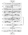
- the block diagram of the principal part of the ion trap mass spectrometer by one Example of this invention The flowchart which shows the procedure of ion selection operation in the ion trap mass spectrometer of a present Example.
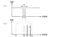
- the schematic of the frequency spectrum of the voltage applied to an end cap electrode The figure which shows an example of the ion selection in the ion trap mass spectrometer of a present Example.
- FIG. 1 is a configuration diagram of a main part of an ion trap mass spectrometer according to the present embodiment.
- the three-dimensional quadrupole ion trap 1 includes an annular ring electrode 11 whose inner surface has a rotating one-leaf hyperboloid shape, and an inner surface provided so as to sandwich the ring electrode 11.
- a pair of end cap electrodes having a curved shape (the left side in FIG. 1 is referred to as an inlet end cap electrode 12 and the right side as an outlet end cap electrode 13).
- the main voltage generator 6 is connected to the ring electrode 11, and the auxiliary voltage generator 7 is connected to the end cap electrodes 12 and 13.
- An ion source 2 is disposed outside the entrance-side end cap electrode 12, and ions generated by the ion source 2 pass through the ion entrance port 14 formed in the approximate center of the entrance-side end cap electrode 12 in the ion trap 1.
- a time-of-flight mass separator (TOF) 3 is disposed outside the exit-side end cap electrode 13, and ions ejected through an ion emission port 15 drilled at substantially the center of the exit-side end cap electrode 13. Is introduced into the TOF 3 and after reaching the detector 4 after flying in the flight space of the TOF 3, is detected.
- the detector 4 outputs a detection signal corresponding to the amount of ions that have reached the data processing unit 5.
- the data processor 5 receives the detection signal and creates a mass spectrum (MS n spectrum) based on the detection signal.
- the main voltage generator 6 and the auxiliary voltage generator 7 are controlled by a control signal supplied from the controller 8 so as to generate an alternating voltage (high frequency voltage) having a predetermined frequency and a predetermined amplitude, respectively.
- the control unit 8 is mainly configured by a computer including a CPU, a ROM, a RAM, and the like, and includes a broadband voltage data generation unit 81 and a sine wave voltage data generation unit 82 as functional blocks. In these functional blocks, digital data of a broadband voltage and a sine wave voltage as described later are generated, and the auxiliary voltage generator 7 converts the digital data into an analog signal by a built-in D / A converter, and a drive amplifier, etc. A voltage is applied to the end cap electrodes 12 and 13 via.
- FIG. 2 is a flowchart showing the procedure of ion selection operation in the ion trap mass spectrometer of the present embodiment
- FIG. 3 is a schematic diagram of the frequency spectrum of the voltage applied to the end cap electrodes 12 and 13.
- MS analysis normal mass analysis without cleavage
- the target sample is introduced into the ion source 2 to generate various ions derived from the target sample, and these ions are introduced into the ion trap 1 and temporarily accumulated. At this time, ion mass selection is not performed.
- a predetermined DC voltage to one or both of the end cap electrodes 12 and 13 at a predetermined timing
- energy is simultaneously applied to the ions in the ion trap 1 and emitted from the ion emission port 15.
- ions are introduced into the TOF 3 to fly and detected by the detector 4. Since the flight time of each ion in the TOF 3 depends on the mass of the ion, the data processing unit 5 converts the flight time obtained from the detection signal from the detector 4 into mass and creates a mass spectrum.
- the selection of the precursor ion may be specified by the user or may be automatically performed according to a predetermined standard.
- mass information of an ion that is close to the mass and is estimated to remain in the ion trap 1 by the first ion exclusion process described later is also obtained from the mass spectrum. Such information is sent to the control unit 8.
- the target sample is introduced into the ion source 2 to generate various ions derived from the target sample, and these ions are introduced into the ion trap 1 and temporarily accumulated (step S3). Thereafter, an ion sorting operation is executed. First, a rough first ion exclusion process is executed. That is, the broadband voltage data generation unit 81 of the control unit 8 generates a voltage (broadband voltage) having a broadband frequency component having a notch with a predetermined frequency width including a frequency corresponding to the mass m of the target ion (step S4). .
- broadband voltage data having a notch with a frequency width of ⁇ ⁇ f centered on a frequency f0 corresponding to the mass of the target ion, that is, matching the natural frequency of the target ion is generated (FIG. 3 ( a)).
- the lower limit frequency and the upper limit frequency of the broadband voltage are not shown in FIG. 3A, in practice, appropriate lower limit frequency and upper limit frequency can be determined.
- the generation of the broadband voltage data as described above can be performed, for example, by performing arithmetic processing for adding and synthesizing a large number of sine wave waveforms at predetermined frequency steps except for the notch portion (range of f1 to f2). . Further, for example, by using a method as proposed by the present applicant in Japanese Patent No. 3470671, it is possible to generate appropriate broadband voltage data while suppressing the amount of calculation.
- the auxiliary voltage generator 7 D / A converts the broadband voltage data and applies the broadband voltage to the end cap electrodes 12 and 13 through the drive amplifier (step S5). Then, among the various ions captured by the electric field formed by the high-frequency voltage applied to the ring electrode 11 from the main voltage generator 6, other than ions having masses corresponding to the frequency range f1 to f2 of the notch. Ions vibrate resonantly. The oscillated ions collide with the inner surfaces of the end cap electrodes 12 and 13 or are discharged from the ion entrance 14 or the ion exit 15 to disappear. In other words, only ions having a mass corresponding to the frequency range of the notch of the broadband voltage remain in the internal space of the ion trap 1.
- the sine wave voltage data generation unit 82 of the control unit 8 generates sine wave voltage data of a single frequency (for example, f3 in FIG. 3B) corresponding to the mass of unnecessary ions near the target ions. (Step S6). If it is known that the unnecessary ions are isotope ions as described above, the mass information of the unnecessary ions is obtained from the mass spectrum obtained by the MS analysis, and the frequency of the sine wave voltage is obtained from the mass information. Can be decided.
- Step S6 When this sine wave voltage data is sent to the auxiliary voltage generator 7, the auxiliary voltage generator 7 D / A converts the sine wave voltage data and applies the sine wave voltage to the end cap electrodes 12, 13 through the drive amplifier.
- Step S6 As a result, among the ions remaining in the internal space of the ion trap 1, only ions having a mass corresponding to the frequency f3 are selectively resonantly oscillated and collide with the inner surfaces of the end cap electrodes 12 and 13, It disappears by being discharged from the entrance 14 or the ion exit 15 (step S7).
- step S8 Only one kind of unnecessary ions is eliminated by applying a sine wave voltage of a single frequency. If there are other unnecessary ions having different masses, it is necessary to continue to use a sine wave voltage of another frequency. Therefore, if there is an unnecessary ion having another mass, NO is determined in step S8, the process returns to step S6, and the sine wave voltage data generation unit 82 has a frequency corresponding to the mass of another unnecessary ion (for example, FIG.
- the sine wave voltage data of f4) in (b) is generated and sent to the auxiliary voltage generator 7. Thereby, other unnecessary ions are also excluded from the ion trap 1 as described above.
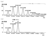
- the distribution of isotope ions of a molecule whose composition formula is C 200 H 400 O 20 is as shown in FIG. Among them, m / z 3124.0356 having the smallest mass is a monoisotopic ion, and this is a target ion.
- ions other than these isotope groups and ions in the range of A in FIG. 4A in the isotope group are excluded.
- the remaining ions are as shown in FIG. That is, in addition to the target ions, two types of unnecessary ions, m / z 3125.0389 and m / z 3126.0422, remain. Therefore, only these two kinds of unnecessary ions are targeted, and sine wave voltages of two frequencies corresponding to them are sequentially applied to the end cap electrodes 12 and 13 to eliminate these ions.
- the mass of unnecessary ions remaining after executing the elimination of coarse ions using a broadband voltage is known, and the number of types of unnecessary ions is relatively small.
- the frequency of the sine wave voltage may be swept within a predetermined range, specifically, a sine wave voltage having a frequency even by a minute frequency step may be applied.
- FIG. 5 is a graph showing an example of the relationship between the mass-to-charge ratio of ions and the vibration frequency when the amplitude of the high-frequency voltage applied to the ring electrode 11 is used as a parameter.
- a sinusoidal voltage having a certain frequency is applied to the end cap electrodes 12, 13.
- the mass of ions that oscillate resonantly changes even when applied to.
- the amplitude of the high frequency voltage applied to the ring electrode 11 is sequentially changed or swept within a predetermined range in a state where a sine wave voltage having a certain single frequency is applied to the end cap electrodes 12 and 13. In this way, the same effect as the frequency change or sweep of the sine wave voltage described above can be obtained.
- the said Example uses the ion selection method characteristic for this invention for the selection of the precursor ion in the case of MS / MS analysis, it can be utilized for the precursor ion selection of MS n analysis whose n is 3 or more. Is natural. That is, the present invention is useful when performing ion selection such that only ions having a specific mass remain in the ion trap.
- the present invention is applied to a three-dimensional quadrupole ion trap, but the present invention is also applicable to a linear ion trap.
- the precursor ions were selected by the ion trap, then the precursor ions were cleaved in the ion trap to generate product ions, and the product ions were subjected to mass analysis by TOF. You may make it perform mass spectrometry. Further, the generation of ions can also be performed inside the ion trap 1.
Landscapes
- Chemical & Material Sciences (AREA)
- Analytical Chemistry (AREA)
- Other Investigation Or Analysis Of Materials By Electrical Means (AREA)
- Electron Tubes For Measurement (AREA)
Abstract
各種イオンをイオントラップ(1)内に蓄積した後、所定周波数幅のノッチを有する広帯域電圧をエンドキャップ電極(12、13)に印加することで、目的イオンと比較的質量差が大きなイオンを短時間で排除する。この段階では、目的イオンと質量が近いイオンはイオントラップ(1)内に残る。次に、先の処理で排除できなかった不要なイオンをターゲットとし、そのイオンの質量に対応した周波数の正弦波電圧をエンドキャップ電極(12、13)に印加することで、一種ずつ不要なイオンを排除する。そして、最終的に目的イオンのみをイオントラップ(1)内に残し、開裂操作を行ってプロダクトイオンを生成し、そのプロダクトイオンを質量分析する。これにより、目的イオンの選別を高速に且つ高精度・高分解能で行うことができる。
Description
本発明は、電場によってイオンを捕捉して蓄積することが可能なイオントラップを備えるイオントラップ質量分析装置に関し、更に詳しくは、イオントラップ内に蓄積した各種イオンを選別する技術に関する。
分子量が大きな物質の同定やその構造の解析を行うために、質量分析の1つの手法としてMS/MS分析(タンデム分析)という手法が知られている。一般にMS/MS分析では、まず分析対象物から目的とする特定の質量(質量電荷比m/z)を有するイオンをプリカーサイオンとして選別し、その選別したプリカーサイオンを衝突誘起解離(CID)などの手法により開裂させ、各種のプロダクトイオンを生成する。その後、それらプロダクトイオンを質量分析することによって、目的とするイオンの質量や化学構造についての情報を得ることができる。また、1回の開裂操作では十分に小さな質量のイオンにならない場合もあるため、開裂操作と質量選別とを複数回繰り返すMSn分析が実行されることもある。
上述したようなMSn分析を行うために、3次元四重極型のイオントラップがよく用いられる。このイオントラップは、内側面が回転1葉双曲面形状を有する1個の環状のリング電極と、それを挟むように対向して設けられた、内側面が回転2葉双曲面形状を有する一対のエンドキャップ電極とから構成され、リング電極とエンドキャップ電極との間に高周波電圧を印加することにより、これら電極で囲まれる空間に四重極電場を形成し、この電場の作用により、空間内で生成された又は外部から導入されたイオンを捕捉して蓄積する。MS/MS分析を行う場合には、イオントラップ内空間に各種イオンを保持した後に、プリカーサイオンの選別行程として、目的とする特定の質量を持つイオンのみを残し、それ以外の不要なイオンをイオントラップ内空間から排除するような選別操作を実行する。
具体的には、次のようなイオン選別方法が知られている。即ち、イオントラップ内空間に各種イオンが捕捉された状態で、対向する一対のエンドキャップ電極間に逆位相の高周波電圧を印加すると、その高周波電圧の周波数と一致する固有周波数(振動数)を有するイオンが共鳴して振動する。その共鳴振動の振幅は次第に大きくなり、やがてそのイオンはイオントラップ内空間から飛び出したり電極内面に衝突したりして排除される。共鳴振動するイオンの質量はその固有周波数と所定の関係を有する。したがって、或る質量を持つ不要なイオンを排除するには、そのイオンの質量に応じた周波数の正弦波電圧をエンドキャップ電極に印加すればよい。排除したいイオンの質量が様々である場合、残したい目的イオンに対応した周波数を除き、正弦波電圧の周波数を所定範囲で掃引することで不要なイオンを排除することができる。
しかしながら、液体クロマトグラフやガスクロマトグラフで成分分離された試料を質量分析する場合、順次導入される試料成分の分析漏れを起こさないために1回のMS/MS分析の高速化を図る必要がある。上記のように正弦波電圧の周波数を掃引することでプリカーサイオンを選別する方法では時間が掛かり、分析の高速化の要求を満たせない。周波数の掃引幅(周波数ステップ幅)を粗くすれば時間短縮が可能であるが、排除されないイオンが残る可能性が高く、分析の精度を低下させる。
プリカーサイオン選別の別の方法として、特許文献1には、残したい目的イオンに対応した周波数にノッチを持つ(つまり、その周波数成分を持たないような)周波数スペクトルを有する広帯域の交流電圧(以下「広帯域電圧」という)をエンドキャップ電極に印加する方法が開示されている。こうした方法によれば、そのノッチ周波数に応じた質量電荷比を有するイオンのみが共鳴振動せずにイオントラップ内空間に留まり、それ以外のイオンはイオントラップ内空間から排除される。上記のようなノッチを有する広帯域電圧の生成方法としては、多数の周波数の相違する正弦波電圧を合成する、ホワイトノイズにノッチを形成する、といった方法が知られている。
しかしながら、実際には、或る単一周波数の正弦波電圧をエンドキャップ電極に印加した場合、その周波数に完全に対応した一種の質量を有するイオンのみが共鳴振動するのではなく、それに質量が近いイオンも共鳴振動してしまう。そのため、目的イオンをイオントラップ内に残すためには、該イオンに対応した周波数を含む或る程度の周波数幅のノッチを設ける必要があり、目的イオンの質量に近い不所望のイオンも同時にイオントラップ内に残ってしまう傾向にある。こうした不所望のイオンをイオントラップ内空間から排除しようとしてノッチの周波数幅を狭めると、目的イオンの一部も排除されてしまい、目的イオンの量が減って分析感度が下がるという問題が起こる。
本発明は上記課題を解決するために成されたものであり、その目的とするところは、イオントラップ内空間に捕捉されている各種イオンの中で目的とするイオンを高い確率で残しつつ、それに近い質量を持つ不要なイオンを確実に排除することができ、しかもそうしたイオン選別操作を高速に行うことが可能なイオントラップ質量分析装置を提供することにある。
上記課題を解決するために成された本発明は、複数の電極により構成され、それら電極の少なくとも1つに印加される電圧によって形成される電場の作用によりイオンを保持することが可能なイオントラップを有し、そのイオントラップ内に各種イオンを保持した後に、特定の質量を有するイオンのみを該イオントラップ内に残すようにイオン選別を行うイオントラップ質量分析装置において、
a)イオントラップ内に残す目的イオンの質量に対応する周波数を含む所定の周波数範囲にノッチを有する広帯域電圧を生成し、イオントラップを構成する複数の電極の少なくとも1つに前記広帯域電圧を印加する第1イオン排除手段と、
b)前記第1イオン排除手段によりイオントラップ内のイオン排除を行った後に、イオントラップ内に残留する又は残留すると推定される不要なイオンを共鳴振動させる単一周波数の正弦波電圧を生成し、イオントラップを構成する複数の電極の少なくとも1つに前記正弦波電圧を印加する第2イオン排除手段と、
を備えることを特徴としている。
a)イオントラップ内に残す目的イオンの質量に対応する周波数を含む所定の周波数範囲にノッチを有する広帯域電圧を生成し、イオントラップを構成する複数の電極の少なくとも1つに前記広帯域電圧を印加する第1イオン排除手段と、
b)前記第1イオン排除手段によりイオントラップ内のイオン排除を行った後に、イオントラップ内に残留する又は残留すると推定される不要なイオンを共鳴振動させる単一周波数の正弦波電圧を生成し、イオントラップを構成する複数の電極の少なくとも1つに前記正弦波電圧を印加する第2イオン排除手段と、
を備えることを特徴としている。
本発明に係るイオントラップ質量分析装置の典型的な一態様として、前記イオントラップは、環状のリング電極と、該リング電極を挟むように配設された一対のエンドキャップ電極とから成るものとすることができる。即ち、このイオントラップはいわゆる3次元四重極型イオントラップである。
このようなイオントラップでは、リング電極に高周波電圧を印加し、それにより形成する電場の作用によりイオンをイオントラップ内空間に閉じ込めて保持することができる。そして、その状態でエンドキャップ電極に交流電圧を印加すると、その電圧の周波数に応じた特定の質量を持つイオンが共鳴振動するから、その現象を利用してイオントラップ内空間から不要なイオンを排除することができる。即ち、本発明に係るイオントラップ質量分析装置の一態様では、前記第1及び第2イオン排除手段は、イオン排除のための電圧、つまりノッチを有する広帯域電圧や単一周波数の正弦波電圧を、エンドキャップ電極に印加する構成とすればよい。
ノッチを有する広帯域電圧の生成方法としては従来知られている各種の方法を採ることができ、例えば、そのノッチの周波数範囲を除いた所定周波数範囲に亘り、適宜の周波数ステップ毎の周波数を有する多数の正弦波電圧を合成する方法や、或いは、まずノッチのない広帯域電圧を生成し、その後にノッチの周波数成分を取り除く方法、などが考えられる。
本発明に係るイオントラップ質量分析装置では、イオントラップ内空間に保持されている各種イオンの中で、第1イオン排除手段により、目的イオンから比較的質量が離れているイオンが共鳴振動により排除される。換言すれば、目的イオンに質量が近いイオンがある場合には、そうしたイオンは目的イオンと共にイオントラップ内空間に残る。次に、第2イオン排除手段により、単一周波数の正弦波電圧が例えばエンドキャップ電極に印加されると、その周波数に対応した質量を有するイオンが選択的に共鳴振動され、イオントラップ内空間から排除される。
第1イオン排除手段によるイオン排除が終了した段階で複数種の不要イオンが未だイオントラップ内空間に残っている場合には、不要イオンの質量に対応した複数の正弦波電圧を順に印加する、つまりは掃引することにより、目的イオンを残したまま複数種の不要イオンを排除することができる。単一周波数の正弦波電圧を用いれば、高い精度及び分解能で以て狭い質量範囲のイオンを排除することができるので、イオントラップ内空間に保持されている目的イオンの量を殆ど減らすことなく、それに質量がごく近い不要なイオンを効率良く排除することができる。
また、エンドキャップ電極に正弦波電圧が印加された際に、それによって共鳴振動するイオンの質量は、リング電極に印加されているイオン保持用の高周波電圧の振幅にも依存している。そこで、複数種の不要イオンを排除したい場合、第2イオン排除手段は、イオン排除用の正弦波電圧をエンドキャップ電極に印加しつつ、リング電極に印加しているイオン保持用の高周波電圧の振幅を順に変化させる、つまり掃引するようにしてもよい。
本発明に係るイオントラップ質量分析装置において、第1イオン排除手段によるイオン排除が終了した段階で残る可能性のあるイオンの質量は、開裂操作を伴わない質量分析を実行して得られるマススペクトルから求めることができる。即ち、例えばMS/MS分析のためのプリカーサイオンの選別を行う際には、MS分析で得られるマススペクトルから、第1イオン排除手段によるイオン排除が終了した段階で残るイオンの質量を求めることができる。
また、これを一般化して、MSn(nは2以上の整数)分析を行う場合に、第2イオン排除手段は、MSn-1分析により得られたマススペクトル情報を用いて、印加する正弦波電圧の周波数を決定する構成とすることができる。或いは、MSn分析を行う場合に、第2イオン排除手段は、MSn-1分析により得られたマススペクトル情報を用いて、リング電極に印加しているイオン保持用の高周波電圧の振幅を決定する構成としてもよい。
さらにまた、多くの分子由来のイオンは、天然存在比が最大の同位体のみで構成されたイオンのみならず、それ以外の同位体を含むイオン(同位体イオン)が存在するが、通常、前者のみを目的イオンとするため、後者は質量が近い不要なイオンとなる。こうした同位体イオンが存在する場合、実際の質量分析を行わなくても、第1イオン排除手段によるイオン排除の後にイオントラップ内空間に残るものと推定することができる。したがって、イオントラップ内空間に残留し得るイオンについて、こうした確度の高い推定が可能な場合には、開裂を伴わない質量分析を実行する必要はない。
本発明に係るイオントラップ質量分析装置によれば、まず広帯域電圧を用いて殆どの不要なイオンを短時間で排除し、その後に、目的イオンと質量が近い少数の不要イオンを高い精度及び分解能で以て排除し、目的イオンのみを選択的にイオントラップ内空間に残すことができる。したがって、目的イオンの選別を高速且つ高精度・高分解能で行うことができる。また、目的イオンの減少を抑えられるので、高い分析感度を実現することができ、目的イオン以外の不要なイオンは確実に排除できるので、マススペクトルに現れるノイズを軽減することができ、定性分析、定量分析ともに精度が高まる。
1…イオントラップ
11…リング電極
12…入口側エンドキャップ電極
13…出口側エンドキャップ電極
14…イオン入射口
15…イオン出射口
2…イオン源
3…飛行時間型質量分離器(TOF)
4…検出器
5…データ処理部
6…主電圧発生部
7…補助電圧発生部
8…制御部
81…広帯域電圧データ生成部
82…正弦波電圧データ生成部
11…リング電極
12…入口側エンドキャップ電極
13…出口側エンドキャップ電極
14…イオン入射口
15…イオン出射口
2…イオン源
3…飛行時間型質量分離器(TOF)
4…検出器
5…データ処理部
6…主電圧発生部
7…補助電圧発生部
8…制御部
81…広帯域電圧データ生成部
82…正弦波電圧データ生成部
本発明の一実施例によるイオントラップ質量分析装置について、図面を参照して説明する。図1は本実施例によるイオントラップ質量分析装置の要部の構成図である。
3次元四重極型のイオントラップ1は、内面が回転1葉双曲面形状を有する1個の環状のリング電極11と、それを挟むように対向して設けられた、内面が回転2葉双曲面形状を有する一対のエンドキャップ電極(図1中の左方を入口側エンドキャップ電極12、右方を出口側エンドキャップ電極13という)とにより構成される。リング電極11には主電圧発生部6が接続され、エンドキャップ電極12、13には補助電圧発生部7が接続される。
入口側エンドキャップ電極12の外側にはイオン源2が配設され、イオン源2で生成されたイオンは入口側エンドキャップ電極12のほぼ中央に穿設されたイオン入射口14を通してイオントラップ1内に導入される。一方、出口側エンドキャップ電極13の外側には飛行時間型質量分離器(TOF)3が配設され、出口側エンドキャップ電極13のほぼ中央に穿設されたイオン出射口15を通して排出されたイオンはTOF3に導入され、TOF3の飛行空間を飛行した後に検出器4に到達して検出される。検出器4は到達したイオンの量に応じた検出信号をデータ処理部5に出力する。データ処理部5は検出信号を受け、これに基づいてマススペクトル(MSnスペクトル)を作成する。
主電圧発生部6及び補助電圧発生部7は制御部8から与えられる制御信号により、それぞれ所定周波数及び所定振幅の交流電圧(高周波電圧)を発生するように制御される。制御部8はCPU、ROM、RAMなどを含むコンピュータを中心に構成され、機能ブロックとして、広帯域電圧データ生成部81と正弦波電圧データ生成部82とを含む。これら機能ブロックでは、それぞれ後述するような広帯域電圧及び正弦波電圧のデジタルデータが生成され、補助電圧発生部7は内蔵するD/A変換器でこのデジタルデータをアナログ信号に変換し、駆動アンプなどを介して電圧をエンドキャップ電極12、13に印加する。
次に、本実施例のイオントラップ質量分析装置の特徴的な動作の一例を図2、図3により説明する。図2は本実施例のイオントラップ質量分析装置におけるイオン選別操作の手順を示すフローチャート、図3はエンドキャップ電極12、13に印加される電圧の周波数スペクトルの概略図である。
まず、目的試料に対するMS分析(開裂を伴わない通常の質量分析)を実行して、マススペクトルを取得する(ステップS1)。即ち、目的試料をイオン源2に導入して目的試料由来の各種のイオンを発生させ、それらイオンをイオントラップ1内に導入して一旦蓄積する。このときにはイオンの質量選別を行わない。そして、エンドキャップ電極12、13の一方又は両方に所定のタイミングで所定の直流電圧を印加することにより、イオントラップ1内のイオンに一斉にエネルギーを付与し、イオン出射口15から出射させる。そして、イオンをTOF3に導入して飛行させ、検出器4により検出する。TOF3における各イオンの飛行時間はそのイオンの質量に依存するから、データ処理部5では検出器4による検出信号から求まる飛行時間を質量に換算し、マススペクトルを作成する。
次に、得られたマススペクトルを用いて、MS/MS(=MS2)分析を実行する対象の目的イオン、つまりプリカーサイオンを決定する(ステップS2)。このプリカーサイオンの選定は、ユーザが指定するようにしてもよいし、或いは予め定めておいた基準に則って自動的に行うようにしてもよい。また、プリカーサイオンが定まると、それに質量が近く後述する第1イオン排除処理によりイオントラップ1内に残ると推測されるイオンの質量情報もマススペクトルから求まる。こうした情報が制御部8に送られる。
一般的に原子には同位体が存在するので、分子由来のイオンにも、天然存在比が最大の同位体のみで構成されたイオンのみならず、それ以外の同位体を含む同位体イオンが複数存在する。これら同位体イオンの質量は例えば1ずつ相違する。モノアイソトピックイオン(同位体が含まれないイオン)を対象としてMS/MS分析(又はそれ以上のMSn分析)を行うのが一般的であるから、目的成分由来のモノアイソトピックイオンを目的イオンとすると、その同位体イオンは不要なイオンとなる。この場合、目的イオンとその同位体イオンとは質量が近いので、同位体イオンは第1イオン排除処理によりイオントラップ1内に残ると推測されるイオンとなり得る。
引き続いて行われるMS/MS分析では、目的試料をイオン源2に導入して目的試料由来の各種のイオンを発生させ、それらイオンをイオントラップ1内に導入して一旦蓄積する(ステップS3)。その後に、イオン選別操作を実行するが、まず粗い第1イオン排除処理を実行する。即ち、制御部8の広帯域電圧データ生成部81は、目的イオンの質量mに対応する周波数を含む所定の周波数幅のノッチを有する広帯域周波数成分を持つ電圧(広帯域電圧)を生成する(ステップS4)。具体的には、目的イオンの質量に対応した、つまりはその目的イオンの固有振動数に一致する周波数f0を中心とし、±Δfの周波数幅のノッチを有する広帯域電圧データを生成する(図3(a)参照)。但し、図3(a)では広帯域電圧の下限周波数及び上限周波数を記載していないが、実際には、適宜の下限周波数及び上限周波数を定めることができる。
上述のような広帯域電圧データの生成は、例えば、そのノッチ部分(f1~f2の範囲)を除いて所定の周波数ステップの多数の正弦波波形を加算合成する演算処理を行うことで行うことができる。また、例えば、本出願人が特許第3470671号公報で提案しているような方法を用いることで、演算量を抑えつつ適切な広帯域電圧データを生成することができる。
この広帯域電圧データを補助電圧発生部7に送ると、補助電圧発生部7は広帯域電圧データをD/A変換し、駆動アンプを通して広帯域電圧をエンドキャップ電極12、13に印加する(ステップS5)。すると、主電圧発生部6からリング電極11に印加されている高周波電圧により形成される電場によって捕捉されている各種イオンの中で、ノッチの周波数範囲f1~f2に相当する質量を持つイオン以外のイオンは共鳴振動する。振動したイオンはエンドキャップ電極12、13の内面に衝突したり、イオン入射口14やイオン出射口15から排出されたりして消失する。換言すれば、広帯域電圧のノッチの周波数範囲に相当する質量を持つイオンのみが、イオントラップ1の内部空間に残る。
但し、ノッチの周波数幅に対応した質量幅は例えば数Da程度と広めであるため、目的イオンのみならず不要なイオンの一部も残ることになる。そこで、次に、残った不要なイオンを排除するために第2イオン排除処理を実行する。即ち、制御部8の正弦波電圧データ生成部82は、目的イオンの近傍の不要なイオンの質量に相当する単一周波数(例えば図3(b)中のf3)の正弦波電圧データを生成する(ステップS6)。いま、上述のように不要なイオンが同位体イオンであることが分かっているとすれば、MS分析により得たマススペクトルから不要イオンの質量情報を得て、この質量情報から正弦波電圧の周波数を決めることができる。
そして、この正弦波電圧データを補助電圧発生部7に送ると、補助電圧発生部7は正弦波電圧データをD/A変換し、駆動アンプを通して正弦波電圧をエンドキャップ電極12、13に印加する(ステップS6)。すると、イオントラップ1の内部空間に残っていたイオンの中で、上記周波数f3に対応した質量を持つイオンのみが選択的に共鳴振動し、エンドキャップ電極12、13の内面に衝突したり、イオン入射口14やイオン出射口15から排出されたりして消失する(ステップS7)。
単一周波数の正弦波電圧の印加により排除される不要イオンは一種のみであり、質量の相違する別の不要イオンがある場合には、引き続き、別の周波数の正弦波電圧を用いる必要がある。そこで、別の質量を持つ不要イオンがある場合には、ステップS8でNOと判断され、ステップS6に戻り、正弦波電圧データ生成部82は別の不要イオンの質量に対応した周波数(例えば図3(b)中のf4)の正弦波電圧データを生成し、これを補助電圧発生部7へと送る。これにより、上記説明と同様に、別の不要イオンもイオントラップ1から排除される。
全ての不要イオンの排除が終了すればイオン選別は終わり、イオントラップ1内には目的イオンのみが残留した状態となる。そこで、続いてイオントラップ1内にCIDガスを導入して目的イオンの開裂を促進させ(ステップS9)、それにより生成された各種プロダクトイオンをイオントラップ1から一斉に出射させてTOF3に導入することにより、目的イオン由来のプロダクトイオンの質量分離を行ってMS/MSスペクトルを作成する(ステップS10)。
具体例を挙げて説明すると、いま組成式がC200H400O20である分子の同位体イオンの分布は図4(a)に示すようになる。この中で、質量が最小のm/z3124.0356がモノアイソトピックイオンであり、これが目的イオンである。例えば、広帯域電圧の印加により、これら同位体群以外のイオンと、同位体群の中で図4(a)中のAの範囲のイオンが排除されるものとすると、その時点でイオントラップ1内に残っているイオンは図4(b)に示すようになる。つまり、目的イオンのほかに、m/z3125.0389、m/z3126.0422の2種の不要なイオンが残っている。そこで、この2種の不要イオンのみをターゲットとして、それらに対応した2つの周波数の正弦波電圧を順にエンドキャップ電極12、13に印加することで、それらイオンをそれぞれ排除すればよい。
なお、実際には、或る単一周波数の正弦波電圧をエンドキャップ電極12、13に印加したときに、完全に一致したイオンのみが共鳴振動するのではなく、質量が若干ずれたイオンも共鳴振動する。したがって、排除したいイオンの質量と周波数との関係は完全に対応していなくてもよく、若干周波数がずれていても不要イオンを排除することができる。
上記実施例の場合、広帯域電圧を用いた粗いイオンの排除を実行した後に残留する不要イオンの質量が既知であり、しかもそのイオンの種類が比較的少なかったが、不要イオンの種類が多い場合には、正弦波電圧の周波数を所定の範囲で掃引する、具体的には周波数を微小周波数ステップずつすらした正弦波電圧を印加するようにしてもよい。
また、イオントラップ1の内部空間でのイオンの振動周波数はイオンの質量に依存するほか、リング電極11に印加される高周波電圧の振幅にも依存する。図5はリング電極11に印加される高周波電圧の振幅をパラメータとしたときの、イオンの質量電荷比とその振動周波数との関係の一例を示すグラフである。このように、リング電極11に印加される高周波電圧の振幅を変化させることで質量電荷比と振動周波数との関係が変化するから、或る一定の周波数の正弦波電圧をエンドキャップ電極12、13に印加した状態でも共鳴振動するイオンの質量は変化する。したがって、或る一定の単一周波数の正弦波電圧をエンドキャップ電極12、13に印加した状態で、リング電極11に印加する高周波電圧の振幅を順に変化させたり、或いは所定の範囲で掃引することによっても、上述した正弦波電圧の周波数の変化や掃引と同様の効果を得ることができる。
なお、上記実施例はMS/MS分析の際のプリカーサイオンの選別に本発明に特徴的なイオン選別手法を用いたものであるが、nが3以上のMSn分析のプリカーサイオン選別に利用できることは当然である。即ち、特定の質量を持つイオンのみをイオントラップ内に残すようなイオン選別を実行する際に、本発明は有用である。
また、上記実施例は本発明を3次元四重極型イオントラップに適用したものであるが、本発明はリニア型のイオントラップにも適用可能である。また、上記実施例はイオントラップでプリカーサイオンを選別した後に、イオントラップ内でプリカーサイオンを開裂させてプロダクトイオンを生成し、プロダクトイオンをTOFで質量分析していたが、イオントラップ自体でプロダクトイオンの質量分析を行うようにしてもよい。また、イオンの生成についてもイオントラップ1の内部で行うこともできる、
Claims (7)
- 複数の電極により構成され、それら電極の少なくとも1つに印加される電圧によって形成される電場の作用によりイオンを保持することが可能なイオントラップを有し、そのイオントラップ内に各種イオンを保持した後に、特定の質量を有するイオンのみを該イオントラップ内に残すようにイオン選別を行うイオントラップ質量分析装置において、
a)イオントラップ内に残すイオンの質量に対応する周波数を含む所定の周波数範囲が欠けた広帯域周波数成分を持つ電圧を生成し、複数の電極の少なくとも1つに印加する第1イオン排除手段と、
b)該第1イオン排除手段によりイオントラップ内のイオン排除を行った後に、イオントラップ内に残留する又は残留すると推定される不要なイオンを共鳴振動させる単一周波数の正弦波電圧を生成し、複数の電極の少なくとも1つに印加する第2イオン排除手段と、
を備えることを特徴とするイオントラップ質量分析装置。 - 請求項1に記載のイオントラップ質量分析装置であって、前記イオントラップは、環状のリング電極と、該リング電極を挟むように配設された一対のエンドキャップ電極とから成ることを特徴とするイオントラップ質量分析装置。
- 請求項2に記載のイオントラップ質量分析装置であって、前記第1イオン排除手段及び第2イオン排除手段は、イオン排除のための広帯域電圧及び正弦波電圧を前記エンドキャップ電極に印加することを特徴とするイオントラップ質量分析装置。
- 請求項3に記載のイオントラップ質量分析装置であって、前記第2イオン排除手段は、正弦波電圧をエンドキャップ電極印加する際にその周波数を掃引することを特徴とするイオントラップ質量分析装置。
- 請求項3に記載のイオントラップ質量分析装置であって、前記第2イオン排除手段は、イオン排除用の正弦波電圧をエンドキャップ電極に印加する際に、前記リング電極に印加しているイオン保持用の高周波電圧の振幅を掃引することを特徴とするイオントラップ質量分析装置。
- 請求項3~5のいずれかに記載のイオントラップ質量分析装置であって、MSn(nは2以上の整数)分析を行う場合に、前記第2イオン排除手段は、MSn-1分析により得られたマススペクトル情報を用いて、印加する正弦波電圧の周波数を決定することを特徴とするイオントラップ質量分析装置
- 請求項5に記載のイオントラップ質量分析装置であって、MSn(nは2以上の整数)分析を行う場合に、前記第2イオン排除手段は、MSn-1分析により得られたマススペクトル情報を用いて、前記リング電極に印加しているイオン保持用の高周波電圧の振幅を決定することを特徴とするイオントラップ質量分析装置
Priority Applications (1)
| Application Number | Priority Date | Filing Date | Title |
|---|---|---|---|
| PCT/JP2008/000098 WO2009095948A1 (ja) | 2008-01-28 | 2008-01-28 | イオントラップ質量分析装置 |
Applications Claiming Priority (1)
| Application Number | Priority Date | Filing Date | Title |
|---|---|---|---|
| PCT/JP2008/000098 WO2009095948A1 (ja) | 2008-01-28 | 2008-01-28 | イオントラップ質量分析装置 |
Publications (1)
| Publication Number | Publication Date |
|---|---|
| WO2009095948A1 true WO2009095948A1 (ja) | 2009-08-06 |
Family
ID=40912322
Family Applications (1)
| Application Number | Title | Priority Date | Filing Date |
|---|---|---|---|
| PCT/JP2008/000098 Ceased WO2009095948A1 (ja) | 2008-01-28 | 2008-01-28 | イオントラップ質量分析装置 |
Country Status (1)
| Country | Link |
|---|---|
| WO (1) | WO2009095948A1 (ja) |
Cited By (2)
| Publication number | Priority date | Publication date | Assignee | Title |
|---|---|---|---|---|
| JP2013516036A (ja) * | 2009-12-23 | 2013-05-09 | アカデミア シニカ | 携帯用質量分析のための装置および方法 |
| CN103703360A (zh) * | 2011-08-03 | 2014-04-02 | 株式会社岛津制作所 | 质量分析数据解析方法以及装置 |
Citations (3)
| Publication number | Priority date | Publication date | Assignee | Title |
|---|---|---|---|---|
| WO2002025265A1 (en) * | 2000-09-20 | 2002-03-28 | Hitachi, Ltd. | Probing method using ion trap mass spectrometer and probing device |
| JP2003203601A (ja) * | 2001-12-28 | 2003-07-18 | Mitsubishi Heavy Ind Ltd | 化学物質の検出装置および化学物質の検出方法 |
| JP2006092750A (ja) * | 2004-09-21 | 2006-04-06 | Hitachi High-Technologies Corp | イオントラップ質量分析方法および装置 |
-
2008
- 2008-01-28 WO PCT/JP2008/000098 patent/WO2009095948A1/ja not_active Ceased
Patent Citations (3)
| Publication number | Priority date | Publication date | Assignee | Title |
|---|---|---|---|---|
| WO2002025265A1 (en) * | 2000-09-20 | 2002-03-28 | Hitachi, Ltd. | Probing method using ion trap mass spectrometer and probing device |
| JP2003203601A (ja) * | 2001-12-28 | 2003-07-18 | Mitsubishi Heavy Ind Ltd | 化学物質の検出装置および化学物質の検出方法 |
| JP2006092750A (ja) * | 2004-09-21 | 2006-04-06 | Hitachi High-Technologies Corp | イオントラップ質量分析方法および装置 |
Cited By (3)
| Publication number | Priority date | Publication date | Assignee | Title |
|---|---|---|---|---|
| JP2013516036A (ja) * | 2009-12-23 | 2013-05-09 | アカデミア シニカ | 携帯用質量分析のための装置および方法 |
| CN103703360A (zh) * | 2011-08-03 | 2014-04-02 | 株式会社岛津制作所 | 质量分析数据解析方法以及装置 |
| CN103703360B (zh) * | 2011-08-03 | 2016-02-24 | 株式会社岛津制作所 | 质量分析数据解析方法以及装置 |
Similar Documents
| Publication | Publication Date | Title |
|---|---|---|
| JP4756096B2 (ja) | 質量分析計 | |
| JP6090479B2 (ja) | 質量分析装置 | |
| JP4894918B2 (ja) | イオントラップ質量分析装置 | |
| US8481924B2 (en) | MS/MS data processing | |
| CN104641452B (zh) | 离子阱中的离子选择方法及离子阱装置 | |
| JP4687787B2 (ja) | 質量分析方法及び質量分析装置 | |
| JP4894916B2 (ja) | イオントラップ質量分析装置 | |
| JP5124293B2 (ja) | 質量分析計および質量分析方法 | |
| CN110506320B (zh) | 具有增加的占空比的质谱分析 | |
| US8164053B2 (en) | Mass analyzer and mass analyzing method | |
| JP3791455B2 (ja) | イオントラップ型質量分析装置 | |
| CN106341983A (zh) | 优化光谱数据的方法 | |
| CN107923872B (zh) | 串联型质谱分析装置 | |
| WO2011007528A1 (ja) | 質量分析計及び質量分析方法 | |
| WO2017126006A1 (ja) | イオントラップ質量分析装置及び該装置を用いた質量分析方法 | |
| JP4709024B2 (ja) | 反応装置及び質量分析装置 | |
| JP4631219B2 (ja) | イオントラップ型質量分析装置 | |
| US6525312B1 (en) | Mass spectrometer with method for real time removal of background signal | |
| JP2008257982A (ja) | 質量分析装置 | |
| JP5737144B2 (ja) | イオントラップ質量分析装置 | |
| EP3044805A1 (en) | Rf-only detection scheme and simultaneous detection of multiple ions | |
| WO2009095948A1 (ja) | イオントラップ質量分析装置 | |
| JP5094362B2 (ja) | 質量分析装置およびその制御方法 | |
| GB2564018A (en) | Method of optimising spectral data | |
| JP5206605B2 (ja) | イオントラップ質量分析装置 |
Legal Events
| Date | Code | Title | Description |
|---|---|---|---|
| 121 | Ep: the epo has been informed by wipo that ep was designated in this application |
Ref document number: 08710302 Country of ref document: EP Kind code of ref document: A1 |
|
| NENP | Non-entry into the national phase |
Ref country code: DE |
|
| 122 | Ep: pct application non-entry in european phase |
Ref document number: 08710302 Country of ref document: EP Kind code of ref document: A1 |
|
| NENP | Non-entry into the national phase |
Ref country code: JP |