WO2009090735A1 - 動きベクトル検出方法及び装置、並びに、プラズマディスプレイパネルの駆動方法及びプラズマディスプレイ装置 - Google Patents
動きベクトル検出方法及び装置、並びに、プラズマディスプレイパネルの駆動方法及びプラズマディスプレイ装置 Download PDFInfo
- Publication number
- WO2009090735A1 WO2009090735A1 PCT/JP2008/050421 JP2008050421W WO2009090735A1 WO 2009090735 A1 WO2009090735 A1 WO 2009090735A1 JP 2008050421 W JP2008050421 W JP 2008050421W WO 2009090735 A1 WO2009090735 A1 WO 2009090735A1
- Authority
- WO
- WIPO (PCT)
- Prior art keywords
- motion vector
- detection area
- detection
- area
- plasma display
- Prior art date
- Legal status (The legal status is an assumption and is not a legal conclusion. Google has not performed a legal analysis and makes no representation as to the accuracy of the status listed.)
- Ceased
Links
Images



Classifications
-
- H—ELECTRICITY
- H04—ELECTRIC COMMUNICATION TECHNIQUE
- H04N—PICTORIAL COMMUNICATION, e.g. TELEVISION
- H04N5/00—Details of television systems
- H04N5/14—Picture signal circuitry for video frequency region
- H04N5/144—Movement detection
- H04N5/145—Movement estimation
-
- G—PHYSICS
- G06—COMPUTING OR CALCULATING; COUNTING
- G06T—IMAGE DATA PROCESSING OR GENERATION, IN GENERAL
- G06T7/00—Image analysis
- G06T7/20—Analysis of motion
- G06T7/262—Analysis of motion using transform domain methods, e.g. Fourier domain methods
-
- G—PHYSICS
- G09—EDUCATION; CRYPTOGRAPHY; DISPLAY; ADVERTISING; SEALS
- G09G—ARRANGEMENTS OR CIRCUITS FOR CONTROL OF INDICATING DEVICES USING STATIC MEANS TO PRESENT VARIABLE INFORMATION
- G09G3/00—Control arrangements or circuits, of interest only in connection with visual indicators other than cathode-ray tubes
- G09G3/20—Control arrangements or circuits, of interest only in connection with visual indicators other than cathode-ray tubes for presentation of an assembly of a number of characters, e.g. a page, by composing the assembly by combination of individual elements arranged in a matrix no fixed position being assigned to or needed to be assigned to the individual characters or partial characters
- G09G3/22—Control arrangements or circuits, of interest only in connection with visual indicators other than cathode-ray tubes for presentation of an assembly of a number of characters, e.g. a page, by composing the assembly by combination of individual elements arranged in a matrix no fixed position being assigned to or needed to be assigned to the individual characters or partial characters using controlled light sources
- G09G3/28—Control arrangements or circuits, of interest only in connection with visual indicators other than cathode-ray tubes for presentation of an assembly of a number of characters, e.g. a page, by composing the assembly by combination of individual elements arranged in a matrix no fixed position being assigned to or needed to be assigned to the individual characters or partial characters using controlled light sources using luminous gas-discharge panels, e.g. plasma panels
- G09G3/288—Control arrangements or circuits, of interest only in connection with visual indicators other than cathode-ray tubes for presentation of an assembly of a number of characters, e.g. a page, by composing the assembly by combination of individual elements arranged in a matrix no fixed position being assigned to or needed to be assigned to the individual characters or partial characters using controlled light sources using luminous gas-discharge panels, e.g. plasma panels using AC panels
-
- G—PHYSICS
- G06—COMPUTING OR CALCULATING; COUNTING
- G06T—IMAGE DATA PROCESSING OR GENERATION, IN GENERAL
- G06T2207/00—Indexing scheme for image analysis or image enhancement
- G06T2207/10—Image acquisition modality
- G06T2207/10016—Video; Image sequence
-
- G—PHYSICS
- G06—COMPUTING OR CALCULATING; COUNTING
- G06T—IMAGE DATA PROCESSING OR GENERATION, IN GENERAL
- G06T2207/00—Indexing scheme for image analysis or image enhancement
- G06T2207/20—Special algorithmic details
- G06T2207/20016—Hierarchical, coarse-to-fine, multiscale or multiresolution image processing; Pyramid transform
-
- G—PHYSICS
- G09—EDUCATION; CRYPTOGRAPHY; DISPLAY; ADVERTISING; SEALS
- G09G—ARRANGEMENTS OR CIRCUITS FOR CONTROL OF INDICATING DEVICES USING STATIC MEANS TO PRESENT VARIABLE INFORMATION
- G09G2320/00—Control of display operating conditions
- G09G2320/10—Special adaptations of display systems for operation with variable images
- G09G2320/106—Determination of movement vectors or equivalent parameters within the image
Definitions
- the present invention relates to a motion vector detection method and apparatus, and a plasma display panel driving method and plasma display apparatus.
- the number of the two-dimensional array of pixels be (k, l). If the region for detecting the motion vector is N ⁇ N pixels (N is a natural number), the pixel number is within the range of the expression (1).
- (u, v) is an address in the frequency space and satisfies the expression (3).
- ⁇ is the Kronecker delta and takes a value as shown in equation (7).
- ⁇ (k, l) has a peak at ( ⁇ , ⁇ ), whereby a motion vector can be detected. That is, the value of (k, l) that gives the peak of ⁇ (k, l) is the motion vector. In this way, the motion vector (k, l) can be obtained.
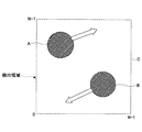
- FIG. 8 is a diagram showing an example in which there are a plurality of regions having different motion vector directions in the same detection region.
- the region A moves in the x positive direction and the y positive direction.
- B moves in the x negative direction and the y negative direction, and the directions of the motion vectors are different.
- FIG. 9 is a diagram showing a case where a large repetitive pattern area D exists in the screen and is larger than the area C where the motion vector is detected.
- the amount of motion cannot be determined.
- an example of how the inverse Fourier transform ⁇ (k, l) of F ′ (u, v) and F (u, v) for detecting a motion vector will be shown as follows. become that way.
- N if N is a multiple of 4, N can be expressed as in equation (8).
- the image data f (k, l) can be expressed as in equation (9).
- F (u, v) can be zero, so in the calculation for obtaining ⁇ (k, l), a term of F (u, v) that does not become zero is calculated. This corresponds to calculating only the spatial frequency component included in the display image.
- ⁇ (k, l) has a peak at a 4-pixel cycle on the x-axis, and a motion vector cannot be determined.
- the detection area to be calculated may be too narrow or the detection area may be too wide. In such a case, there is a problem that the motion vector cannot be determined.
- the present invention provides a motion vector detection method and apparatus capable of appropriately detecting motion vectors having different orientations and sizes in the same image, and a plasma display panel.
- An object of the present invention is to provide a driving method and a plasma display device.
- a motion vector detection method is a method for detecting a motion vector between frames before and after a moving image to be displayed on a screen having pixels arranged in a matrix.
- a plurality of detection areas for detecting motion vectors are set on the screen such that a low-order detection area is included in a high-order detection area.
- For each of the detection areas of the plurality of layers obtain a Fourier transform of each of the preceding and following frames, calculate a motion vector, A motion vector in the lowest order detection area is obtained from an average of motion vectors detected in the lowest order detection area and a plurality of higher order detection areas including the lowest order detection area among the detection areas of the plurality of hierarchies. It is characterized by determining.
- a second invention is the motion vector detection method according to the first invention,
- the detection region is set so that a boundary of the higher-order detection region matches a boundary of the lower-order detection region.
- a third invention is a motion vector detection method according to the second invention, wherein The m-th detection area is set as an area of 2 m ⁇ 2 m pixels, The lowest order detection area is set as a 2 ⁇ 2 pixel area.
- the driving method of the plasma display panel according to the fourth invention is as follows: A motion vector is detected by the motion vector detection method according to any one of the first to third aspects; By using the motion vector, the lighting pattern of the subframe is controlled corresponding to the movement of the image.
- a motion vector detection device is a motion vector detection device that detects a motion vector between frames before and after a moving image displayed on a screen in which pixels are arranged in a matrix.
- a detection area setting means for setting a plurality of hierarchies on the screen such that a detection area for detecting the motion vector is included in a high-order detection area;
- motion vector calculation means for performing a Fourier transform on each of the preceding and following frames, and calculating a motion vector between the preceding and following frames based on these.
- a motion vector in the lowest order detection area is obtained from an average of motion vectors detected in the lowest order detection area and a plurality of higher order detection areas including the lowest order detection area among the detection areas of the plurality of hierarchies.
- Motion vector determining means for determining.
- motion vectors between frames of moving images displayed on the screen can be detected in an appropriately sized inspection area including motion vectors, and large repetitive patterns and motion vectors with different orientations are in the same frame. Even if it exists in the image, it is possible to appropriately detect the motion vector based on each.
- the 6th invention is the motion vector detection apparatus which concerns on 5th invention.
- the detection area setting means sets the detection area so that a boundary of the higher-order detection area matches a boundary of the lower-order detection area.
- a seventh invention is the motion vector detection device according to the sixth invention, wherein
- the detection area setting means sets the plurality of hierarchies to an m-th order detection area as an area of 2 m ⁇ 2 m pixels and to set the lowest order detection area as an area of 2 ⁇ 2 pixels. To do.
- the boundary of the m-th detection region can be a hierarchical relationship that matches the boundary of the (m ⁇ 1) -th detection region, and the arithmetic processing for determining the motion vector can be facilitated. .
- a plasma display device is a plasma display device having a plasma display panel driven by a subframe driving method, A motion vector detection device according to any one of claims 5 to 7, Subframe control means for controlling the lighting pattern of the subframe based on the motion vector detected by the motion vector detection device; And a plasma display panel driving circuit for driving the plasma display panel based on the lighting pattern.
- motion vector detection errors can be reduced, blurring of moving images displayed on the screen can be reduced, and image quality can be improved.
- FIG. 6 is a diagram illustrating an example in which a motion vector is displayed on a screen 10.
- FIG. 6 is an overall configuration diagram of a plasma display device according to a third embodiment. It is a figure which shows the structural example of 1 frame FR of an image. It is a figure showing an example of control of the lighting pattern of subframes SF1 to SF3.
- FIG. 10 is an operation flowchart of the plasma display device according to the third embodiment. It is the figure which showed the example which has an area
- FIG. 1 is a diagram illustrating a hierarchical relationship of a motion vector detection method and apparatus according to a first embodiment to which the present invention is applied, a plasma display panel driving method, and a motion vector detection region of the plasma display apparatus.
- a detection area for obtaining motion vector information by Fourier transform is defined.
- the size of the detection area is a 2 m ⁇ 2 m pixel area, and the minimum area is a 2 ⁇ 2 pixel area so that FFT (Fast Fourier Transform) is performed at high speed.
- FFT Fast Fourier Transform
- the screen of the plasma display device as an object of the embodiment will be described by taking a screen of 1920 ⁇ 1080 pixels as an example, but the maximum size of the repeated pattern region that can appear is the entire screen.
- the screen area is expanded to 2048 ⁇ 2048 pixels, and the pixel data of the area outside the original screen of 1902 ⁇ 1080 pixels is set to 0.
- FIG. 1 shows a motion vector detection region having 2 m ⁇ 2 m pixels.
- a detection area of 2 m ⁇ 2 m is referred to as an m-th detection area.
- the (m ⁇ 1) th order detection area becomes a pixel area of 2 m ⁇ 1 ⁇ 2 m ⁇ 1
- the mth order detection area is twice as long as the (m ⁇ 1) th order detection area.
- the boundary of the m-th detection region coincides with the boundary of the (m ⁇ 1) -th detection region.
- the minimum area is the primary detection area and the maximum area is the 11th detection area. If a number is assigned in the set of m-th detection areas and this is expressed as the n-th, the m-th detection area can be expressed as ⁇ mn .
- the motion vector of the moving image between the preceding and following frames is detected by setting a plurality of layers having different detection areas on the screen. .
- motion vector candidates are obtained in each detection region.
- Fourier transform is obtained in the detection area ⁇ mn of the frame of interest and the next frame.
- the pixel data in the frame of interest is set to f mn (k, l), and the pixel data in the next frame is set to f ′ mn (k, l).
- the pixel data is the Y value (luminance value) of the pixel, but another amount may be used.
- the address (coordinates) of the pixel is (k, l), but it is assumed that the address (k, l) is assigned to each target detection area. Therefore, the range of k and l is expressed as in equation (13) if it is an inspection region of the mth order hierarchy.
- the inverse Fourier transform ⁇ mn (k, l) represents the movement of the detection region ⁇ mn .
- the motion vector ( ⁇ , ⁇ ) 1n of the detection region ⁇ 1n can be determined by the equation (18).
- M is the order of the detection area of the highest hierarchy (11 in this example)
- ⁇ (m, n) is a set of m-th order detection area numbers including the detection area ⁇ 1n .
- Equation (18) means the average of motion vectors detected in the detection region including the detection region ⁇ 1n . Since an accurate motion vector can be detected in a small detection area included in the repeated pattern area, a value close to the accurate motion vector can be obtained by taking the average of the equation (18).
- the motion vector detection area is set by dividing the screen, but the detection area is set in a plurality of layers with different sizes, and the preceding and following frames are set for each layer.
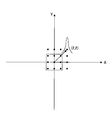
- FIG. 2 is a diagram illustrating an example of motion vector detection.
- FIG. 2 shows an example in which the motion vector (2, 2) is detected by the inverse Fourier transform ⁇ mn (k, l) giving the motion vector information.
- the motion vector (2, 2) takes a value of 1 and the other motion vectors take a value of 0. Means.
- the motion vector itself is detected for each detection region, not the motion vector information ⁇ mn (k, l).
- FIG. 3 is a diagram illustrating an example in which the motion vector described in FIG. 2 is displayed on the screen 10 having the pixels 11 arranged in a matrix.
- motion vectors (1, 1) and (-1, -1) having the same magnitude in the opposite direction are detected in the upper left part.
- motion vectors having various sizes and directions are redundantly included in the inspection areas of a plurality of layers having different inspection areas. In other layers, it is detected as a small vector value or too large to be detected. Therefore, if the motion vector information of the moving image of the preceding and following frames is detected in each inspection region in different layers of the plurality of inspection regions, and all of these are added and averaged, the most in all layers A prominent motion vector is detected so as to emerge from the noise. Since the finally calculated motion vector is calculated from the average, it is expressed by the lowest-order motion vector.
- the motion vector detection method it is not always possible to detect an accurate motion vector for each pixel, but it is possible to always calculate an appropriate motion vector between frames before and after. . In other words, for any moving image, it is possible to avoid a situation where a motion vector cannot be calculated or an obvious erroneous vector is calculated. It is possible to calculate a highly reliable motion vector without error in a large direction.
- the setting of detection areas in a plurality of layers has a relationship of 2 m ⁇ 2 m , and an area obtained by dividing the m-th detection area vertically and horizontally is the (m ⁇ 1) -th detection area.
- an area obtained by dividing the m-th detection area vertically and horizontally is the (m ⁇ 1) -th detection area.
- there are various relationships such as a 3 m ⁇ 3 m relationship, and an area obtained by dividing the m-th detection area into three vertical and horizontal becomes the (m ⁇ 1) -th detection area. Can be set.
- the hierarchy is set so that the boundary of the m-th detection region matches the boundary of the (m ⁇ 1) -th detection region.
- the detection area only needs to be larger than the (m ⁇ 1) th detection area.
- a detection area having a 2 ⁇ 2 pixel area is a detection area having a 3 ⁇ 3 pixel area.
- the example in which the number of pixels on the screen 10 is 2048 ⁇ 2048 is described as an example, but the actual arrangement of the pixels 11 on the screen 10 is as follows.
- the setting of the detection area may be variously changed according to the application, or the detection area may be set to a rectangle instead of the same number of pixels in the vertical and horizontal directions. However, in such a case, the boundaries of the layers may not match, so that instead of calculating the motion vector in the lowest detection region, the motion vector may be detected for each pixel.
- the setting of detection areas of a plurality of hierarchies may be set in advance for the screen 10 or may be configured to be selectable. In the case of enabling selection, for example, it may be possible to change by an operation of a user or the like, or an automatic control for grasping a rough movement state of an image and setting an appropriate detection region based on the situation. May be.
- the arithmetic processing of the motion detection method described in the first and second embodiments may be realized by arithmetic processing means such as various electronic circuits, MPU (Micro Processing Unit), and ASIC (Application Specific Specific Integrated Circuit). By using these, it is possible to configure a motion vector detection device that implements the motion vector detection method according to the present embodiment as a device.
- arithmetic processing means such as various electronic circuits, MPU (Micro Processing Unit), and ASIC (Application Specific Specific Integrated Circuit).
- FIG. 4 is a functional block diagram showing the overall configuration of the plasma display apparatus according to the third embodiment to which the present invention is applied.
- the plasma display device according to the third embodiment includes a plasma display panel 15, a plasma display panel drive circuit 20, a subframe control unit 30, and a motion vector detection device 40.
- components for receiving a frame image signal and performing necessary signal processing are omitted, and only components necessary for screen display are shown. Therefore, the plasma display apparatus according to the present embodiment may include other elements necessary as a plasma display apparatus such as a signal processing ⁇ correction circuit and a white balance adjustment circuit as necessary.
- the plasma display panel 15 is a self-luminous display device that utilizes light emission associated with gas discharge, and a screen 10 is formed on the display surface.
- the plasma display panel 15 includes a plurality of address electrodes 16, a plurality of scan electrodes (scan electrodes) 17, and a plurality of sustain electrodes (sustain electrodes) 18.
- the plurality of address electrodes 16 are arranged in the vertical direction of the screen 10, and the plurality of scan electrodes 17 and the plurality of sustain electrodes 18 are arranged in the horizontal direction of the screen 10.
- the plurality of sustain electrodes 18 are connected in common.
- a display cell is formed at each intersection of the address electrode 16, the scan electrode 17, and the sustain electrode 18, and each display cell constitutes a pixel 11 on the screen.
- the plasma display panel drive circuit 20 includes an address driver 21, a Y scan driver 22, a Y sustain circuit 23, and an X sustain circuit 24.
- the address driver 21 is connected to the plurality of address electrodes 16 of the plasma display panel 15.
- the Y scan driver 22 includes a drive circuit (driver IC) provided in each scan electrode 17, and each drive circuit is connected to the corresponding scan electrode 17 of the plasma display panel 15.
- the X sustain circuit is connected to the plurality of sustain electrodes 18 of the plasma display panel 15.
- the address driver 21 applies an address pulse to the corresponding address electrode 16 of the plasma display panel 15 according to the image data in the address period in accordance with the control signal of the subframe control means 30.
- the Y scan driver 22 sequentially applies the address pulse to the plurality of scan electrodes 17 of the plasma display panel 15 while shifting the shift pulse in the vertical scanning direction in the address period according to the control signal of the sub-frame control means 30. Thereby, address discharge is performed in the display cell of the corresponding pixel 11.
- the Y sustain circuit 23 applies a periodic sustain pulse to the plurality of scan electrodes 17 of the plasma display panel 15 via the Y scan driver 22 in the sustain period in accordance with the control signal given from the subframe control means 30.
- the X sustain circuit 24 causes the plurality of sustain electrodes 18 of the plasma display panel 15 to have a sustain phase shifted by 180 ° with respect to the sustain pulse of the scan electrode 17 in the sustain period. Apply pulses simultaneously. Thereby, a sustain discharge is performed in the display cell of the corresponding pixel 11.
- the sub-frame control means 30 generates a sub-frame signal from the image data signal of one frame, and for the address driver 21, Y scan driver 22, Y sustain circuit 23 and X sustain circuit 24 of the plasma display panel drive circuit 20. Control means for sending subframe signals to drive these drive circuits.
- the subframe control means 30 generates a subframe signal using the motion vector detected by the motion vector detection device 40.
- FIG. 5 is a diagram illustrating a configuration example of one frame FR of an image.
- the image is formed at 60 frames / second, for example.
- One frame FR is formed by a first subframe SF1, a second subframe SF2,..., An nth subframe SFn. This n is, for example, 10, and corresponds to the number of gradation bits.
- Each of the subframes SF1, SF2, etc., or their generic name is hereinafter referred to as a subframe SF.
- Each subframe SF includes a reset period Tr, an address period Ta, and a sustain (sustain discharge) period Ts.
- the reset period Tr the display cell is initialized.
- the address period Ta light emission or non-light emission of each display cell can be selected by address discharge between the address electrode Aj and the Y electrode Yi.
- the sustain period Ts a sustain discharge is performed between the X electrode Xi and the Y electrode Yi of the selected display cell to emit light.
- the number of times of light emission (the length of the sustain period Ts) by the sustain pulse between the X electrode Xi and the Y electrode Yi is different. Thereby, the gradation value can be determined.
- the sub-frame control means 30 determines the gradation value in this way, but in the plasma display device according to the present embodiment, the motion vector between the previous and next frames is detected for the frame FR shown in FIG. Is used to control the gradation value.
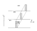
- FIG. 6 is a diagram showing a control example of the lighting pattern of the subframes SF1 to SF3.
- a subframe that emits light corresponding to the motion vector from the first half to the second half of the subframe SF.
- the subframes SF1 to SF3 are sequentially turned on in accordance with the direction of movement of the motion vector. That is, since the user watching the plasma display panel 15 generally moves the line of sight following the moving subject on the screen, the movement position of the user's line of sight is predicted by detecting the motion vector of the subject. Can do.
- the moving images can be smoothly connected in the first half and the second half of the sub-frame SF, and the blur of the moving images can be reduced. it can.
- the sub-frame in the case of image data in which the position indicated by SF1 is emitted in the frame FR, the sub-frame is not continuously emitted at this position, but the decomposed sub-frame is adjusted to the direction of the motion vector. It controls to become the lighting pattern of a frame. Such control is performed by the subframe control means 30 according to the present embodiment.
- the subframe control means 30 performs arithmetic processing for generating and controlling such subframes, and is realized by an electronic circuit having an arithmetic processing function, MPU (Micro Processing Unit), ASIC (Application Specific Specific Integrated Circuit), or the like. May be.
- MPU Micro Processing Unit
- ASIC Application Specific Specific Integrated Circuit
- the motion vector detection device 40 is means for detecting a motion vector of a moving image displayed on the screen 10 of the plasma display panel 15 and executes the motion vector detection method described in the first and second embodiments.
- the motion vector detection device 40 includes a detection area setting unit 41, a motion vector information calculation unit 42, and a motion vector determination unit 43.
- the detection area setting means 41 is a means for setting a plurality of hierarchies of detection areas for detecting motion vectors. As described in the first and second embodiments, the detection areas of a plurality of hierarchies for detecting a motion vector have different sizes depending on the hierarchies, and there is a relationship in which a lower detection area is included in a higher detection area. And set on the screen 10 of the plasma display panel 15.
- the detection area setting unit 41 is configured to store storage means such as a memory for storing the set detection areas, or set detection areas. It may be an arithmetic processing means for detecting a motion vector.
- such a selection function may be provided, or a function that can automatically set the detection area according to the motion of the moving image. May be provided with a function of performing calculation for setting the detection area.
- the contents of the detection area setting performed by the detection area setting means correspond to the contents that define the range of the size of k and l in the m-th layer in the contents described in the first and second embodiments.
- the motion vector information calculation unit 42 is a unit that calculates and calculates motion vector information of a moving image between the previous and next frames for each detection region set by the detection region setting unit.
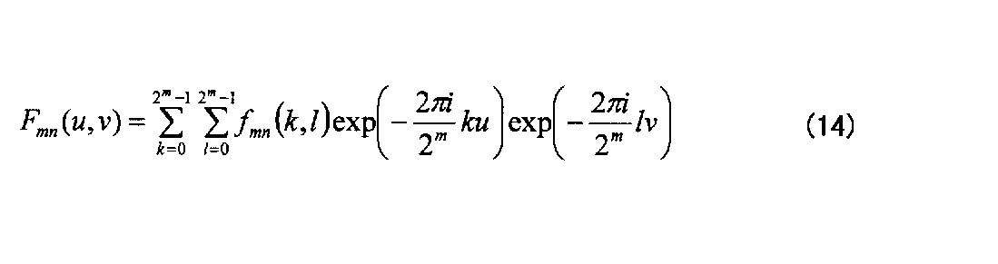
- the calculation of equations (13) to (17) in the first embodiment is performed to calculate motion vector information ⁇ mn (k, l) between the previous and next frames for each of a plurality of layers.
- the motion vector determination unit 43 is a unit for determining and detecting a final motion vector from the motion vector information in a plurality of layers calculated by the motion vector information calculation unit 42. Specifically, an average value of motion vector information ⁇ mn (k, l) of a plurality of layers is calculated using the equation (18) described in the first embodiment, and this is used as a final motion in the lowest layer.
- the vector ( ⁇ , ⁇ ) is determined as 1n .
- the detected motion vector ( ⁇ , ⁇ ) 1n is output from the motion vector detection device 40 to the subframe control means 30, and the motion detected by the subframe control means 30 in generating the subframe signal as described above. A vector is used, and a smooth moving image with less blur can be displayed on the screen 10 of the plasma display panel 15.
- motion vector information calculation means 42 and the motion vector determination means 43 execute such arithmetic processing, and may be realized by arithmetic processing means such as an electronic circuit, MPU, or ASIC.
- the motion vector detection device As described above, by applying the motion vector detection device according to the present embodiment to the plasma display device, the motion vector of the moving image displayed on the screen 10 of the plasma display panel 15 is appropriately detected, and the motion vector is used.
- the plasma display panel 15 can be driven by the method described above, and a plasma display device that can display a smooth moving image with less blur can be obtained.
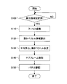
- FIG. 7 is an operation flowchart of the plasma display apparatus according to the third embodiment.
- step 100 it is determined whether or not a motion vector detection region is set by the detection region setting means 41. If detection areas of a plurality of hierarchies are set in advance on the screen 10, the process automatically proceeds to step 110, but if detection area setting change or setting control is performed, has the detection area setting been completed? It is determined whether or not. If the setting is not completed, step 100 is repeated until the setting is completed.
- the motion vector information calculation means 42 calculates the Fourier transform in the detection region between the frame of interest and the next frame, that is, the preceding and following frames. Specifically, the arithmetic processing of the equations (13) to (15) described in the first embodiment is executed, and Fourier transforms F mn (u, v) and F ′ mn (u, v) are obtained.
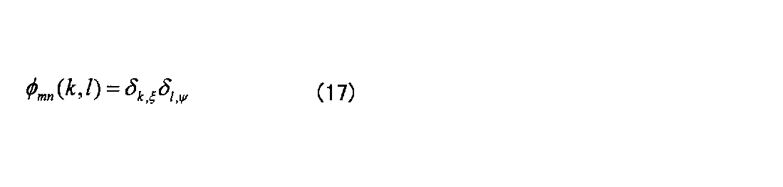
- the motion vector information calculation means 42 calculates motion vector information between the previous and subsequent frames in each detection region of the plurality of layers. Specifically, the calculations of equations (16) and (17) described in the first embodiment are performed, and each motion vector information ⁇ mn (k, l) of the detection region ⁇ mn is calculated by inverse Fourier transform.
- step 130 the motion vector is determined by the motion vector determination means 43. Specifically, the calculation process of the equation (18) described in the first embodiment is executed, and all the motion vector information ⁇ mn (k, l) calculated by the motion vector information calculation unit 42 is summed, and the lowest The next average value is calculated and determined as the motion vector ( ⁇ , ⁇ ) 1n .
- Steps 100 to 130 are a motion vector detection method executed by the motion vector detection device 40.
- the contents so far can be applied not only to a display device using the plasma display panel 15 but also to display devices having various screens 10.
- the motion vector detected by the motion vector detection device 40 is output to the subframe control means 30.
- step 140 the subframe control means 30 performs lighting control of the subframe using the motion vector. Specifically, the movement of the line of sight is predicted from the motion of the subject using the motion vector, and the subframe signal is generated with the lighting pattern of the subframe reflecting this. The generated subframe signal (control signal) is output to the plasma display panel drive circuit 20, thereby controlling the drive of the plasma display panel 15.
- step 150 the plasma display panel drive circuit 20 drives the plasma display panel 15 in accordance with the subframe signal (control signal) sent from the subframe control means 30, and ends the processing flow.
- the driving method of the plasma display panel 15 according to the present embodiment is executed, whereby a smooth moving image can be displayed with less blur.
- the motion vector detection method according to the present embodiment, accurate detection of the motion vector for each pixel is not necessarily performed. However, since the motion vector is detected by a large detection area, the motion vector of the repetitive pattern D is also erroneous. It can be detected without detection.
- the motion vector detection method and apparatus, and the plasma display panel driving method and plasma display apparatus according to the present embodiment can be suitably applied.
- the present invention is applicable to all display devices that display a moving image on a screen using a motion vector.
- it can be suitably applied to a plasma display device using a plasma display panel as a screen.
Landscapes
- Engineering & Computer Science (AREA)
- Physics & Mathematics (AREA)
- Theoretical Computer Science (AREA)
- Multimedia (AREA)
- General Physics & Mathematics (AREA)
- Computer Vision & Pattern Recognition (AREA)
- Mathematical Physics (AREA)
- Power Engineering (AREA)
- Plasma & Fusion (AREA)
- Computer Hardware Design (AREA)
- Signal Processing (AREA)
- Control Of Indicators Other Than Cathode Ray Tubes (AREA)
- Control Of Gas Discharge Display Tubes (AREA)
Abstract
マトリクス状に配列された画素11を有する画面10に表示する動画像の前後フレームSF間の動きベクトル(ξ,ψ)1nを検出する方法であって、 動きベクトルを検出する検出領域を、低次の検出領域が、高次の検出領域に含まれるように前記画面上に複数階層設定し、 前記複数階層の検出領域の各々について、前後フレーム各々のフーリエ変換Fmn(u,v)、F'mn(u,v)を求めて、動きベクトル情報φmn(k,l)を算出し、 前記複数階層の検出領域のうち、最低次の検出領域と、該最低次の検出領域を含む複数の高次の検出領域において検出される動きベクトル情報の平均から、前記最低次の検出領域における動きベクトルを決定することを特徴とする。
Description
本発明は、動きベクトル検出方法及び装置、並びに、プラズマディスプレイパネルの駆動方法及びプラズマディスプレイ装置に関する。
従来から、画像信号処理の分野、特に動画に関する信号処理において、画像中の各物体の動きの方向と大きさ、つまり動きベクトルを検出し、かかる動きベクトルを用いて基準となるフレーム画像からの動きを表現し、動画のデータを表現する技術が知られている。
かかる動きベクトルの検出方法として、フーリエ変換を用いた動きベクトルの検出方法が知られている(特許文献1参照)。以下、この内容について説明する。
まず、画素の2次元配列の番号を(k,l)とする。動きベクトルを検出する領域がN×N画素(Nは自然数)であるとすると、画素番号は、(1)式の範囲内にある。


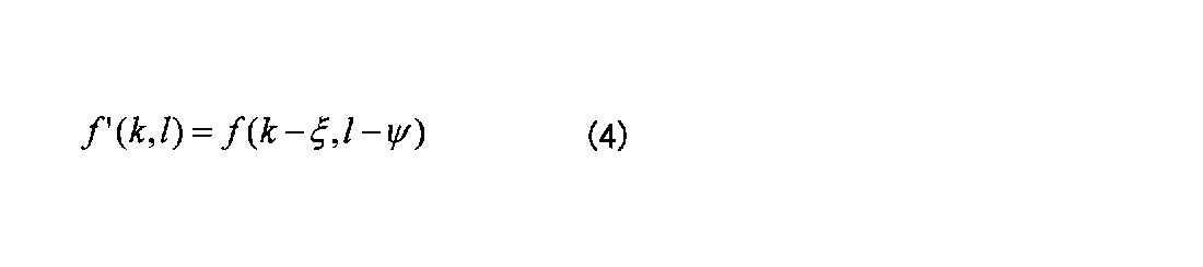

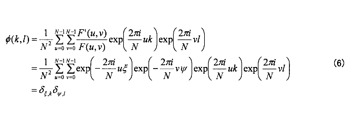

しかしながら、上述の特許文献1に記載の動きベクトル検出方法では、画面全体が一様に動く場合には正確に動きベクトルを検出することができるが、画面の中で動きの異なる領域がある場合、どの領域がどちらに動いているのか分からなくなるという問題があった。
図8は、同一の検出領域内に動きベクトルの向きが異なる領域が複数ある例を示した図である。図8に示すように、x、y方向にそれぞれ0~(N-1)画素の領域を有する検出領域Cがある場合において、領域Aはx正方向、y正方向に動いているが、領域Bはx負方向、y負方向に動いており、両者の動きベクトルの向きは異なっている。このような場合には、検出領域Cが全体としてどの向きに動いているのかが検出できず、また、領域Aと領域Bの動きも検出できないという問題があった。
これを防止するため、画面を細かく分割して動きベクトルの検出を行うと、大きな領域を占める繰り返しパターンが存在した場合に、分割した画面がその領域に対して小さいときに、動きベクトルが検出できないという別の問題を新たに生じてしまう。
図9は、画面中に大きな繰り返しパターン領域Dが存在し、これが動きベクトルを検出する領域Cよりも大きい場合を示した図である。このような場合には、動きベクトル検出領域C内にパターンマッチングを満たしてしまう地点が多く存在してしまうため、動き量を確定することができない。このような場合に、動きベクトルを検出するためのF'(u,v)とF(u,v)の逆フーリエ変換φ(k,l)がどのようになるのかについて一例を示すと、以下のようになる。
まず、Nが4の倍数とすると、Nは(8)式のように表すことができる。



次に、f(k,l)の画像が、1フレームでx方向に4画素動いたとすると、元の画像に重なるので、そのフーリエ変換もF(u,v)と同じであり、(11)式のようになる。
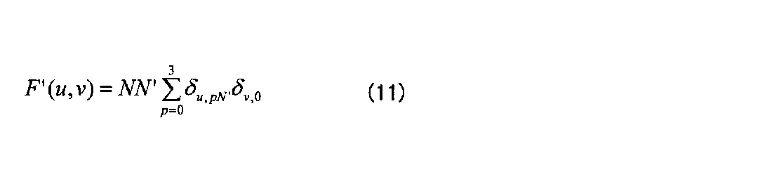

このように、従来技術においては、ある領域の動きベクトル検出を行うのに固定された領域でフーリエ変換を行うため、計算対象とする検出領域が狭すぎる場合と、検出領域が広すぎる場合があり得、かかる場合には、動きベクトルを決定できない状態になるという問題があった。
そこで、本発明は、同一画像に異なる向きや大きさを有する動きベクトルが含まれている場合であっても、これらを適切に検出することができる動きベクトル検出方法及び装置、並びに、プラズマディスプレイパネルの駆動方法及びプラズマディスプレイ装置を提供することを目的とする。
上記目的を達成するため、第1の発明に係る動きベクトル検出方法は、マトリクス状に配列された画素を有する画面に表示する動画像の前後フレーム間の動きベクトルを検出する方法であって、
動きベクトルを検出する検出領域を、低次の検出領域が、高次の検出領域に含まれるように前記画面上に複数階層設定し、
前記複数階層の検出領域の各々について、前後フレーム各々のフーリエ変換を求めて、動きベクトルを算出し、
前記複数階層の検出領域のうち、最低次の検出領域と、該最低次の検出領域を含む複数の高次の検出領域において検出される動きベクトルの平均から、前記最低次の検出領域における動きベクトルを決定することを特徴とする。
動きベクトルを検出する検出領域を、低次の検出領域が、高次の検出領域に含まれるように前記画面上に複数階層設定し、
前記複数階層の検出領域の各々について、前後フレーム各々のフーリエ変換を求めて、動きベクトルを算出し、
前記複数階層の検出領域のうち、最低次の検出領域と、該最低次の検出領域を含む複数の高次の検出領域において検出される動きベクトルの平均から、前記最低次の検出領域における動きベクトルを決定することを特徴とする。
これにより、繰り返しパターンを含む画像のように、検出のために大きな検出領域が必要な動きベクトルと、大きな検出領域では方向が異なる小さな動きベクトルが複数検出され、動きベクトルの決定が困難な場合であっても、領域に応じた適切な動きベクトルを検出することができる。
第2の発明は、第1の発明に係る動きベクトル検出方法において、
前記検出領域を、前記高次の検出領域の境界が、前記低次の検出領域の境界に一致するように設定することを特徴とする。
前記検出領域を、前記高次の検出領域の境界が、前記低次の検出領域の境界に一致するように設定することを特徴とする。
これにより、動きベクトルの決定演算を容易に行うことができる。
第3の発明は、第2の発明に係る動きベクトル検出方法において、
m次の検出領域を、2m×2m画素の領域として設定し、
前記最低次の検出領域を、2×2画素の領域として設定することを特徴とする。
m次の検出領域を、2m×2m画素の領域として設定し、
前記最低次の検出領域を、2×2画素の領域として設定することを特徴とする。
これにより、m次の動きベクトルの検出領域の境界が、(m-1)次の動きベクトルの検出領域の境界に一致するような包含関係を有する階層を設定することができ、動きベクトルの決定演算を容易にすることができるとともに、小さな画素単位を最低次の検出領域とするので、小さな動きベクトルから大きな動きベクトルまで十分考慮して最終的な動きベクトルを決定することができる。
第4の発明に係るプラズマディスプレイパネルの駆動方法は、
第1~3のいずれか一つの発明に係る動きベクトル検出方法により動きベクトルを検出し、
該動きベクトルを用いて、画像の移動に対応してサブフレームの点灯パターンを制御することを特徴とする。
第1~3のいずれか一つの発明に係る動きベクトル検出方法により動きベクトルを検出し、
該動きベクトルを用いて、画像の移動に対応してサブフレームの点灯パターンを制御することを特徴とする。
これにより、視線の移動方向に沿った点灯パターンでサブフレームを点灯させることができ、プラズマディスプレイパネルに、人間の眼に違和感を与えない滑らかな動画像表示を行わせることができる。
第5の発明に係る動きベクトル検出装置は、画素がマトリクス状に配列された画面に表示される動画像の、前後フレーム間における動きベクトルを検出する動きベクトル検出装置であって、
前記画面上に、前記動きベクトルを検出する検出領域を、低次の検出領域が、高次の検出領域に含まれるように、複数階層設定する検出領域設定手段と、
前記複数階層の前記動きベクトル検出領域毎に、前後フレームの各々についてフーリエ変換を行い、これらに基づいて前記前後フレーム間の動きベクトルを算出する動きベクトル算出手段と、
前記複数階層の検出領域のうち、最低次の検出領域と、該最低次の検出領域を含む複数の高次の検出領域において検出される動きベクトルの平均から、前記最低次の検出領域における動きベクトルを決定する動きベクトル決定手段と、を有することを特徴とする。
前記画面上に、前記動きベクトルを検出する検出領域を、低次の検出領域が、高次の検出領域に含まれるように、複数階層設定する検出領域設定手段と、
前記複数階層の前記動きベクトル検出領域毎に、前後フレームの各々についてフーリエ変換を行い、これらに基づいて前記前後フレーム間の動きベクトルを算出する動きベクトル算出手段と、
前記複数階層の検出領域のうち、最低次の検出領域と、該最低次の検出領域を含む複数の高次の検出領域において検出される動きベクトルの平均から、前記最低次の検出領域における動きベクトルを決定する動きベクトル決定手段と、を有することを特徴とする。
これにより、画面に表示される動画像のフレーム間の動きベクトルを、動きベクトルの含まれる適切な大きさの検査領域で検出することができ、大きな繰り返しパターンや、向きが異なる動きベクトルが同一フレーム画像中に存在する場合であっても、各々を踏まえて適切に動きベクトルを検出することができる。
第6の発明は、第5の発明に係る動きベクトル検出装置において、
前記検出領域設定手段は、前記検出領域を、前記高次の検出領域の境界が、前記低次の検出領域の境界に一致するように設定することを特徴とする。
前記検出領域設定手段は、前記検出領域を、前記高次の検出領域の境界が、前記低次の検出領域の境界に一致するように設定することを特徴とする。
これにより、動きベクトル検出のための演算処理を容易に行うことができる。
第7の発明は、第6の発明に係る動きベクトル検出装置において、
前記検出領域設定手段は、前記複数階層を、m次の検出領域を2m×2m画素の領域に設定し、前記最低次の検出領域を2×2画素の領域に設定することを特徴とする。
前記検出領域設定手段は、前記複数階層を、m次の検出領域を2m×2m画素の領域に設定し、前記最低次の検出領域を2×2画素の領域に設定することを特徴とする。
これにより、m次の検出領域の境界が、(m-1)次の検出領域の境界に一致する階層関係とすることができ、動きベクトルを決定するための演算処理を容易にすることができる。
第8の発明に係るプラズマディスプレイ装置は、サブフレーム駆動法により駆動されるプラズマディスプレイパネルを有するプラズマディスプレイ装置であって、
請求項5~7のいずれか一つの発明に係る動きベクトル検出装置と、
該動きベクトル検出装置により検出した動きベクトルに基づいて、サブフレームの点灯パターンを制御するサブフレーム制御手段と、
前記点灯パターンに基づいて、前記プラズマディスプレイパネルを駆動するプラズマディスプレイパネル駆動回路と、を有することを特徴とする。
請求項5~7のいずれか一つの発明に係る動きベクトル検出装置と、
該動きベクトル検出装置により検出した動きベクトルに基づいて、サブフレームの点灯パターンを制御するサブフレーム制御手段と、
前記点灯パターンに基づいて、前記プラズマディスプレイパネルを駆動するプラズマディスプレイパネル駆動回路と、を有することを特徴とする。
これにより、プラズマディスプレイパネルに、動きベクトルを用いて、ボヤケがなく、動きが滑らかな動画像を表示することができる。
本発明によれば、動きベクトルの検出誤差を低減し、画面に表示する動画像のボヤケを低減し、画質を改善することができる。
10 画面
11 画素
15 プラズマディスプレイパネル
16 アドレス電極
17 スキャン電極
18 サステイン電極
20 プラズマディスプレイパネル駆動回路
21 アドレスドライバ
22 Yスキャンドライバ
23 Yスキャン回路
24 Xサステイン回路
30 サブフレーム制御手段
40 動きベクトル検出装置
41 検出領域設定手段
42 動きベクトル情報算出手段
43 動きベクトル決定手段
11 画素
15 プラズマディスプレイパネル
16 アドレス電極
17 スキャン電極
18 サステイン電極
20 プラズマディスプレイパネル駆動回路
21 アドレスドライバ
22 Yスキャンドライバ
23 Yスキャン回路
24 Xサステイン回路
30 サブフレーム制御手段
40 動きベクトル検出装置
41 検出領域設定手段
42 動きベクトル情報算出手段
43 動きベクトル決定手段
本発明をより詳細に説明するために、以下、図面を参照して、本発明を実施するための最良の形態の説明を行う。
図1は、本発明を適用した実施例1に係る動きベクトル検出方法及び装置、並びにプラズマディスプレイパネルの駆動方法及びプラズマディスプレイ装置の動きベクトル検出領域の階層関係を示した図である。
まず、フーリエ変換で動きベクトル情報を求める検出領域を定義する。検出領域の大きさは、FFT(Fast Fourier Transform、高速フーリエ変換)が高速で実行されるように、2m×2mの画素領域として、最小の領域は、2×2画素の領域とする。ここで、実施例の対象とするプラズマディスプレイ装置の画面は、1920×1080画素の画面を例に挙げて説明するが、出現しうる繰り返しパターン領域の最大の大きさは、画面全体である。ここでは、計算の便宜のため、画面領域を2048×2048画素に拡張し、1902×1080画素の本来の画面外の領域の画素データを0とする。
図1は、2m×2mの画素を有する動きベクトルの検出領域を示している。図1において、2m×2mの検出領域をm次の検出領域と呼ぶこととする。すると、(m-1)次の検出領域は、2m-1×2m-1の画素領域となり、m次の検出領域は、(m-1)次の検出領域の縦に2倍、横に2倍の画素領域を各々有することになる。よって、m次の検出領域は、(m-1)次の検出領域の2×2=4倍の検出領域(画素数)を有することになる。また、m次の検出領域の境界が、(m-1)次の検出領域の境界に一致する。
ここで、上述の条件を適用すると、最小領域は1次の検出領域であり、最大領域は11次の検出領域である。m次の検出領域の集合の中で番号を付け、これをn番目と表現することとすると、m次のn番目の検出領域は、Ωmnと表現することができる。本実施例に係る動きベクトル検出方法及び装置においては、このような、検出領域の異なる階層を、画面上に複数階層設定することにより、前後フレーム間の動画像の動きベクトルを検出することになる。
次に、このような複数階層の検出領域が設定された画面における動きベクトルの決定方法について説明する。
まず、各検出領域で動きベクトルの候補を求める。その第1ステップとして、着目しているフレームと、その次のフレームの検出領域Ωmnでのフーリエ変換を求める。着目しているフレームでの画素データをfmn(k,l)とし、次のフレームでの画素データをf'mn(k,l)とする。ここでは、画素データはその画素のY値(輝度値)であるが、別の量を用いてもよい。
ここで、画素の番地(座標)は、(k,l)であるが、対象とする検出領域毎に番地(k,l)を付けるものとする。よって、k、lの範囲は、m次の階層の検査領域であれば、(13)式のように表される。



ここで、逆フーリエ変換φmn(k,l)は、(17)式のように表され、従来技術の(7)式で説明したのと同様に、検出領域Ωmn全体が(ξ,ψ)だけ並行移動するときに、クロネッカーのデルタとなる。
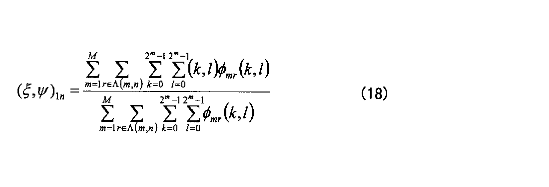
(18)式は、検出領域Ω1nを含む検出領域で検出された動きベクトルの平均を意味する。繰り返しパターン領域に含まれてしまう小さい検出領域で正確な動きベクトルが検出できるので、(18)式の平均を取ることにより、正確な動きベクトルに近い値を得ることができる。
また、画面上に異なる動きをする複数の領域がある場合には、それらを含んでしまう大きな検出領域では、正確な動きベクトルが検出できないが、十分に小さい検出領域では、単一の動きを検出することができ、(18)式の平均を取ることにより、正確な動きベクトルに近い値を得ることができる。
このように、前後フレームの動画像の画像データについて、画面を分割して動きベクトルの検出領域を設定するが、検出領域を異なる大きさで複数階層設定するようにし、これらの階層毎に前後フレーム間の動きベクトルを算出し、最終的にこれらの平均を算出して動きベクトルを決定することにより、個々の階層における重要なベクトルが検出され、更にそれらの平均を取ることにより、全階層を通じて、重要な動きベクトルが際立つようになるので、前後フレーム間の動きベクトルを適切に検出することができる。
実施例2においては、実施例1において、(13)~(18)式を用いて理論的に説明した本実施例に係る動きベクトルの検出方法について、図2及び図3を用いて、具体的な例を挙げて説明する。
図2は、動きベクトルの検出例について示した図である。図2において、動きベクトル情報を与える逆フーリエ変換φmn(k,l)により、動きベクトル(2,2)が検出された例が示されている。このとき、実施例1の(17)式及び従来技術の(7)式で説明したように、動きベクトル(2,2)で1の値をとり、他の動きベクトルは0の値をとることを意味する。なお、実施例2においては、各検出領域について、動きベクトル情報φmn(k,l)ではなく、動きベクトルそのものが検出されたものとして説明を行う。
図3は、図2で説明した動きベクトルが、マトリクス状に配列された画素11を有する画面10上に示された例を示した図である。画面10は、実施例1と同様に、2048×2048個の画素11を有するものとする。画面10は、一部のみが示され、2m×2mで表される検出領域のm=1次の最低次の検出領域からm=3次までの検出領域の総てと、m=4次の検出領域のx軸方向の総て及びy軸方向の半分の領域が示されている。つまり、m=1次の最低次の検出領域を示す1つのマス目には、4画素分の画素領域を含んでいる。なお、m次の各階層について、n番目の検出領域については、画面10の最上行の左端を1番目とし、右に2、3・・番目と移動し、その行が終了したら、次の2行目の左端1列目に移動して順次右に番号を付すものとする。従って、画面10は、最低次のm=1次の検査領域を、1024×1024個有するものとする。
図3において、m=1次の階層の検査領域については、n=1番目の検出領域に、(1,1)の動きベクトルが検出されている。これは、1次の階層の検査領域に、動きベクトルが総て含まれているので、1次の検査領域で検出することができる。同様に、m=1次の階層のn=5番目の検査領域にも、正方向の動きベクトル(1,1)が検出されている。一方、m=1次の階層のn=1030番目の検査領域(2行目の6列目)と、n=2051番目の検査領域(3行目の3列目)には、反対向きの動きベクトル(-1,-1)が検出されている。これらは総て、最低次のm=1次の検査領域で適切に検出される動きベクトルである。
一方、m=1次の階層のn=1026番目の検査領域には、動きベクトル(3,3)が途中まで含まれているが、この検査領域では、動きベクトル(3,3)の総てを含んではいないので、1次の階層では、これを正確に検出することはできない。この場合、検査領域の階層を、m=2次まで上げても、動きベクトル(3,3)は、n=1番目の検査領域をはみ出しており、正確にこの動きベクトル(3,3)を検出することはできない。次に、検査領域の階層を、m=3次まで上げると、3次の階層のn=1番目の検査領域に動きベクトル(3,3)は収まるので、m=3次の階層においては、動きベクトル(3,3)を正確に検出することができる。
ここで、m=3次の階層のn=1番目の検査領域には、他に動きベクトル(1,1)と(-1,-1)も検出される。これらは、m=1次の階層においては、各々の検査領域で単一方向で適切に検出されていた動きベクトルであるが、m=3次の階層の検査領域においては、動きベクトル(3,3)の方が大きく重要な動きベクトルとして検出され、それよりも重要度の小さな動きベクトルとして検出される。
また、m=3次の階層のn=2番目の検査領域において、左上部に反対向きで大きさが同じ動きベクトル(1,1)及び(-1,-1)が検出されるが、これらは、m=1次の階層の検査領域においては、各々単一方向で検出され、重要な大きさを有していたが、m=3次の階層の検査領域においては、その重要度は低下することになる。例えば、他にもっと大きな動きベクトルが同一の検査領域内に存在した場合には、その動きベクトルの方が際立つことになる。一方、これらの動きベクトル(1,1)及び(-1,-1)は、m=2次の階層のn=3番目の検査領域にも共に含まれ、この検査領域においても検出される。この場合は、m=3次の階層のn=2番目の検査領域で検出される場合よりも、重要度は高い動きベクトルとして検出されるが、両者の方向は反対なので、全体としては打ち消しあう動きベクトルとして検出され、m=1次の場合より大きく重要度は低下して検出される。
このように、種々の大きさと方向を有する動きベクトルは、検査領域の異なる複数の階層の検査領域に重複して含まれるが、最も適切な階層で検出された場合は、そこで最適なピーク値が検出され、他の階層では、小さな値のベクトル値として検出されるか、又は大きすぎて検出できないことになる。従って、複数の検査領域の異なる階層で前後フレームの動画像の動きベクトル情報を、各々の検査領域で検出し、これを総て加算して平均を取れば、総ての階層の中で、最も際立った動きベクトルが、ノイズの中から浮かび上がるように検出されることになる。そして、この最終的に算出された動きベクトルは、平均からの算出であるので、最低次の動きベクトルで表現されることになる。
次に、図3に示されている繰り返しパターンDの動きベクトルを検出する方法について説明する。図3において、例えばm=1次の階層や、m=2次の階層でこの繰り返しパターンDの動きベクトルを検出しようとした場合には、動きベクトルのピーク値が周期的に立つことになり、検査領域における動きベクトルを決定することが困難となる。このような場合には、例えばm=3次の階層で動きベクトルを検出した場合には、n=2番目の検査領域であれば、繰り返しパターンDの全体を包含することができ、繰り返しパターンDの全体の前後フレーム間の動きベクトルを算出することが可能となる。
このように、実施例2に係る動きベクトル検出方法によれば、画素毎の正確な動きベクトルを検出することは必ずしもできないが、前後のフレーム間における、適切な動きベクトルを必ず算出することができる。つまり、どのような動画像に対しても、動きベクトルが算出不能であったり、又は明らかな誤ベクトルを算出してしまったりするという事態を回避することができ、若干の誤差はあるものの、常に大きな方向には誤りの無い信頼性の高い動きベクトルを算出することが可能となる。
なお、実施例2においては、複数階層の検出領域の設定は、2m×2mの関係を有し、m次の検出領域を縦横2分割した領域が(m-1)次の検出領域となっている例を挙げて説明したが、例えば、3m×3mの関係を有し、m次の検出領域を縦横3分割した領域が(m-1)次の検出領域となる等、種々の設定を行うことができる。
また、実施例2においては、m次の検出領域の境界が、(m-1)次の検出領域の境界に一致するように階層の設定を行ったが、検出領域の設定は、m次の検出領域が、(m-1)次の検出領域よりも大きければよく、例えば、2×2の画素領域を有する検出領域の高次の検出領域が、3×3の画素領域を有する検出領域であってもよい。例えば、実施例1及び実施例2においては、理解の容易のため、画面10の画素数が2048×2048の縦横同数の例を挙げて説明したが、実際の画面10の画素11の配列は、種々の形式が考えられるので、用途に応じて、検出領域の設定を種々変化させたり、また検出領域を縦横同数の画素数ではなく、長方形に設定したりしてもよい。但し、このような場合には、各階層の境界が一致しないことがあるので、最低次の検出領域における動きベクトルを算出する代わりに、各画素について動きベクトルを検出するようにすればよい。
また、複数の階層の検出領域の設定は、画面10について予め設定しておいてもよいし、選択可能に構成してもよい。選択可能とする場合には、例えば、ユーザ等の操作により変更可能としてもよいし、画像の大まかな動きの状況を把握し、これに基づいて適切な検出領域を設定する自動制御を行うようにしてもよい。
なお、実施例1及び実施例2において説明した動き検出方法の演算処理は、種々の電子回路、MPU(Micro Processing Unit)、ASIC(Application Specific Integrated Circuit)等の演算処理手段により実現されてよい。これらを用いて、本実施例に係る動きベクトル検出方法を装置として実現する、動きベクトル検出装置を構成することができる。
実施例3においては、実施例1又は実施例2において説明した動きベクトル検出方法及び装置を、プラズマディスプレイパネルの駆動方法及びプラズマディスプレイ装置に適用する例について説明する。
図4は、本発明を適用した実施例3に係るプラズマディスプレイ装置の全体構成を示した機能ブロック図である。図4において、実施例3に係るプラズマディスプレイ装置は、プラズマディスプレイパネル15と、プラズマディスプレイパネル駆動回路20と、サブフレーム制御手段30と、動きベクトル検出装置40とを備える。なお、図4においては、フレーム画像信号を受信したり、必要な信号処理等を行ったりする構成要素を省略しており、画面表示に必要な構成要素のみを示している。従って、本実施例に係るプラズマディスプレイ装置は、必要に応じて、信号処理用のγ補正回路や、白バランス調整回路等のプラズマディスプレイ装置として必要な他の要素を備えていてよい。
プラズマディスプレイパネル15は、気体放電に伴う発光を利用した自発光型の表示デバイスであり、表示面には、画面10が構成される。プラズマディスプレイパネル15は、複数のアドレス電極16、複数のスキャン電極(走査電極)17および複数のサステイン電極(維持電極)18を含む。複数のアドレス電極16は、画面10の垂直方向に配列され、複数のスキャン電極17および複数のサステイン電極18は、画面10の水平方向に配列されている。また、複数のサステイン電極18は、共通に接続されている。アドレス電極16、スキャン電極17およびサステイン電極18の各交点には、表示セルが形成され、各表示セルが画面上の画素11を構成する。
プラズマディスプレイパネル駆動回路20は、アドレスドライバ21と、Yスキャンドライバ22と、Yサステイン回路23と、Xサステイン回路24とを有する。アドレスドライバ21は、プラズマディスプレイパネル15の複数のアドレス電極16に接続されている。Yスキャンドライバ22は、各スキャン電極17に設けられた駆動回路(ドライバIC)を内部に備え、各駆動回路がプラズマディスプレイパネル15の対応するスキャン電極17に接続されている。Xサステイン回路は、プラズマディスプレイパネル15の複数のサステイン電極18に接続されている。
アドレスドライバ21は、サブフレーム制御手段30の制御信号に従い、アドレス期間において、画像データに応じてプラズマディスプレイパネル15の該当するアドレス電極16にアドレスパルスを印加する。
Yスキャンドライバ22は、サブフレーム制御手段30の制御信号に従い、アドレス期間において、シフトパルスを垂直走査方向にシフトしつつプラズマディスプレイパネル15の複数のスキャン電極17にアドレスパルスを順に印加する。これにより、該当する画素11の表示セルにおいてアドレス放電が行われる。
Yサステイン回路23は、サブフレーム制御手段30から与えられる制御信号に従い、サステイン期間において、周期的なサステインパルスを、Yスキャンドライバ22を介してプラズマディスプレイパネル15の複数のスキャン電極17に印加する。
Xサステイン回路24は、サブフレーム制御手段30から与えられる制御信号に従い、サステイン期間において、プラズマディスプレイパネル15の複数のサステイン電極18に、スキャン電極17のサステインパルスに対して180°位相のずれたサステインパルスを同時に印加する。これにより、該当する画素11の表示セルにおいてサステイン放電が行われる。
サブフレーム制御手段30は、1フレームの画像データ信号から、サブフレーム信号を生成するとともに、プラズマディスプレイパネル駆動回路20のアドレスドライバ21、Yスキャンドライバ22、Yサステイン回路23及びXサステイン回路24に対してサブフレーム信号を送り、これらの駆動回路を駆動させる制御手段である。本実施例に係るプラズマディスプレイ装置においては、サブフレーム制御手段30は、動きベクトル検出装置40で検出された動きベクトルを用いて、サブフレーム信号の生成を行う。
図5は、画像の1フレームFRの構成例を示す図である。画像は、例えば60フレーム/秒で形成される。1フレームFRは、第1のサブフレームSF1、第2のサブフレームSF2、・・・、第nのサブフレームSFnにより形成される。このnは、例えば10であり、階調ビット数に相当する。サブフレームSF1,SF2等の各々を又はそれらの総称を、以下、サブフレームSFという。
各サブフレームSFは、リセット期間Tr、アドレス期間Ta、及びサステイン(維持放電)期間Tsにより構成される。リセット期間Trでは、表示セルの初期化を行う。アドレス期間Taでは、アドレス電極Aj及びY電極Yi間のアドレス放電により各表示セルの発光又は非発光を選択することができる。サステイン期間Tsでは、選択された表示セルのX電極Xi及びY電極Yi間でサステイン放電を行い、発光を行う。各SFでは、X電極Xi及びY電極Yi間のサステインパルスによる発光回数(サステイン期間Tsの長さ)が異なる。これにより、階調値を決めることができる。
サブフレーム制御手段30は、このようにして階調値を定めるが、本実施例に係るプラズマディスプレイ装置においては、図5に示したフレームFRについて、前後フレーム間での動きベクトルを検出し、これを利用して階調値を調整する制御を行う。
図6は、サブフレームSF1~SF3の点灯パターンの制御例を示した図である。例えば、動きベクトル検出装置40により、図6に示すように、動きベクトル(1,2)が検出された場合には、サブフレームSFの前半から後半にかけて、動きベクトルに対応して発光するサブフレームを並べるようにする。図6においては、動きベクトルの移動の方向に合わせて、サブフレームSF1~3を順次点灯させている。つまり、プラズマディスプレイパネル15を観ているユーザは、一般的に画面上の動く被写体を追う視線の動きをするので、被写体の動きベクトルを検出することにより、ユーザの視線の移動位置を予測することができる。これを利用し、移動する視線上に発光するサブフレームを並べるようにすれば、サブフレームSFの前半と後半で、動画像が滑らかに結ばれるようになり、動画像のボヤケを減少させることができる。図3において、フレームFRにおいて、SF1に示す位置を発光させる画像データの場合には、この位置でサブフレームをずっと発光させるのではなく、分解したサブフレームを、動きベクトルの方向に合わせるようなサブフレームの点灯パターンとなるように制御する。このような制御を、本実施例に係るサブフレーム制御手段30は実行する。
なお、サブフレーム制御手段30は、このようなサブフレームを生成、制御する演算処理を行うので、演算処理機能を有する電子回路、MPU(Micro Processing Unit)、ASIC(Application Specific Integrated Circuit)等により実現されてよい。
図4に戻り、他の構成要素の説明を行う。動きベクトル検出装置40は、プラズマディスプレイパネル15の画面10に表示された動画像の動きベクトルを検出する手段であり、実施例1及び実施例2で説明した動きベクトル検出方法を実行する。動きベクトル検出装置40は、検出領域設定手段41と、動きベクトル情報算出手段42と、動きベクトル決定手段43とを有する。
検出領域設定手段41は、動きベクトルを検出する複数階層の検出領域を設定するための手段である。動きベクトルを検出する複数階層の検出領域は、実施例1及び実施例2において説明したように、階層により大きさが異なり、低次の検出領域が、高次の検出領域に含まれる関係を有し、プラズマディスプレイパネル15の画面10上に設定される。
複数階層の検出領域の設定が、予めなされて固定されている場合には、検出領域設定手段41は、設定された検出領域を記憶しておくメモリ等の記憶手段や、設定された検出領域について動きベクトルの検出を行わせるような演算処理手段であってよい。
また、検出領域の設定が、ユーザの選択により調整可能であれば、そのような選択機能を備えてもよいし、動画像の動きに応じて、自動的に検出領域を設定することができる機能を搭載した場合には、検出領域の設定演算を行う機能を備えていてよい。
なお、検出領域設定手段が行う検出領域設定の内容は、実施例1及び実施例2で説明した内容において、m次の階層におけるk、lの大きさの範囲を定める内容に該当する。
動きベクトル情報算出手段42は、検出領域設定手段で設定された各検出領域について、前後フレーム間の動画像の動きベクトル情報を計算し、算出する手段である。実施例1における(13)~(17)式の演算を行い、複数の階層毎に前後フレーム間の動きベクトル情報φmn(k,l)を算出する。
動きベクトル決定手段43は、動きベクトル情報算出手段42により算出された複数の階層における動きベクトル情報から、最終的な動きベクトルを決定して検出するための手段である。具体的には、実施例1において説明した(18)式を用いて、複数階層の動きベクトル情報φmn(k,l)の平均値を算出し、これを最低次の階層における最終的な動きベクトル(ξ,ψ)1nとして決定する。そして、検出した動きベクトル(ξ,ψ)1nは、動きベクトル検出装置40からサブフレーム制御手段30に出力され、上述のように、サブフレーム制御手段30によるサブフレーム信号の生成に検出された動きベクトルが利用され、滑らかでボヤケの少ない動画像をプラズマディスプレイパネル15の画面10に表示することができる。
なお、動きベクトル情報算出手段42及び動きベクトル決定手段43は、このような演算処理を実行するので、電子回路、MPU、ASIC等の演算処理手段により実現されてよい。
このように、本実施例に係る動きベクトル検出装置をプラズマディスプレイ装置に適用することにより、プラズマディスプレイパネル15の画面10に表示される動画像の動きベクトルを適切に検出し、この動きベクトルを利用した方法によりプラズマディスプレイパネル15を駆動させることができ、ボヤケの少ない滑らかな動画像を表示できるプラズマディスプレイ装置とすることができる。
次に、図7を用いて、実施例3に係る動きベクトル検出装置及びプラズマディスプレイ装置により実行される、動きベクトル検出方法及びプラズマディスプレイパネル15の駆動方法の処理フローについて説明する。図7は、実施例3に係るプラズマディスプレイ装置の動作フロー図である。
ステップ100では、検出領域設定手段41により動きベクトルの検出領域が設定されているか否かが判定される。複数の階層の検出領域が、予め画面10に設定されている場合には、自動的にステップ110に進むが、検出領域の設定変更や設定制御を行う場合には、検出領域設定が終了したか否かが判定される。設定が終了していない場合には、設定が終了するまで、ステップ100を繰り返す。
ステップ110では、動きベクトル情報算出手段42により、着目するフレームと次のフレーム、つまり前後フレーム間の検出領域におけるフーリエ変換が計算される。具体的には、実施例1において説明した(13)~(15)式の演算処理が実行され、フーリエ変換Fmn(u,v)及びF'mn(u,v)が求められる。
ステップ120では、動きベクトル情報算出手段42により、複数の階層の各検出領域における前後フレーム間の動きベクトル情報が算出される。具体的には、実施例1において説明した(16)、(17)式の演算がなされ、逆フーリエ変換により検出領域Ωmnの各動きベクトル情報φmn(k,l)が算出される。
ステップ130では、動きベクトル決定手段43により、動きベクトルの決定がなされる。具体的には、実施例1において説明した(18)式の演算処理が実行され、動きベクトル情報算出手段42により算出された動きベクトル情報φmn(k,l)が総て合計され、その最低次における平均値が算出され、これが動きベクトル(ξ,ψ)1nとして決定される。
ステップ100~130が、動きベクトル検出装置40により実行される動きベクトル検出方法である。ここまでの内容は、プラズマディスプレイパネル15を用いた表示装置に限らず、種々の画面10を有する表示装置に適用することができる。動きベクトル検出装置40により検出された動きベクトルは、サブフレーム制御手段30に出力される。
ステップ140では、サブフレーム制御手段30により、動きベクトルを利用して、サブフレームの点灯制御が行われる。具体的には、動きベクトルを利用して被写体の動きから視線の移動を予測し、これを反映させたサブフレームの点灯パターンでサブフレーム信号を生成する。生成したサブフレーム信号(制御信号)をプラズマディスプレイパネル駆動回路20に出力し、これにより、プラズマディスプレイパネル15の駆動を制御することになる。
ステップ150では、プラズマディスプレイパネル駆動回路20が、サブフレーム制御手段30から送られてきたサブフレーム信号(制御信号)に従い、プラズマディスプレイパネル15の駆動を行い、処理フローを終了する。
このような処理フローにより、本実施例に係るプラズマディスプレイパネル15の駆動方法が実行され、これにより、ボヤケが少なく、滑らかな動画像を表示することができる。
本実施例に係る動きベクトル検出方法及び装置、並びにプラズマディスプレイパネル15の駆動方法及びプラズマディスプレイ装置によれば、パターンマッチングによる動きベクトル検出方法のように、1画素毎の精密な動きベクトルの検出は行わないので、動きベクトルを計算するための回路規模を大幅に削減することができる。
また、そのようなパターンマッチングによる精密な動きベクトルの検出方法では、適合するパターンを発見できなかった場合に、誤検出をするおそれがある。特に、繰り返しパターンを含む画像においては、その蓋然性が高くなる。一方、本実施例に係る動きベクトル検出方法によれば、1画素毎の動きベクトルの精密な検出は必ずしも行わないが、大きな検出領域により動きベクトルを検出するので、繰り返しパターンDの動きベクトルも誤検出なく検出することができる。
本実施例において説明した、被写体の視線に合わせてサブフレームSFの点灯制御を行うプラズマディスプレイパネル15の駆動方法を実行する場合には、1画素毎に精密な動きベクトルを検出することよりも、誤検出により大きく破綻しないことの方が遙かに重要である。このような用途に、本実施例に係る動きベクトル検出方法及び装置、並びに、プラズマディスプレイパネルの駆動方法及びプラズマディスプレイ装置は、好適に適用され得る。
本発明は、動きベクトルを利用して画面に動画像を表示する表示装置全般に適用可能である。特に、画面としてプラズマディスプレイパネルを用いたプラズマディスプレイ装置に好適に適用可能である。
Claims (8)
- マトリクス状に配列された画素を有する画面に表示する動画像の前後フレーム間の動きベクトルを検出する方法であって、
動きベクトルを検出する検出領域を、低次の検出領域が、高次の検出領域に含まれるように前記画面上に複数階層設定し、
前記複数階層の検出領域の各々について、前後フレーム各々のフーリエ変換を求めて、動きベクトル情報を算出し、
前記複数階層の検出領域のうち、最低次の検出領域と、該最低次の検出領域を含む複数の高次の検出領域において検出される動きベクトル情報の平均から、前記最低次の検出領域における動きベクトルを決定することを特徴とする動きベクトル検出方法。 - 前記検出領域を、前記高次の検出領域の境界が、前記低次の検出領域の境界に一致するように設定することを特徴とする請求項1に記載の動きベクトル検出方法。
- m次の検出領域を、2m×2m画素の領域として設定し、
前記最低次の検出領域を、2×2画素の領域として設定することを特徴とする請求項2に記載の動きベクトル検出方法。 - 請求項1乃至3のいずれか一項に記載の動きベクトル検出方法により動きベクトルを検出し、
該動きベクトルを用いて、画像の移動に対応してサブフレームの点灯パターンを制御することを特徴とするプラズマディスプレイパネルの駆動方法。 - 画素がマトリクス状に配列された画面に表示される動画像の、前後フレーム間における動きベクトルを検出する動きベクトル検出装置であって、
前記画面上に、前記動きベクトルを検出する検出領域を、低次の検出領域が、高次の検出領域に含まれるように、複数階層設定する検出領域設定手段と、
前記複数階層の前記動きベクトル検出領域毎に、前後フレームの各々についてフーリエ変換を行い、これらに基づいて前記前後フレーム間の動きベクトル情報を算出する動きベクトル情報算出手段と、
前記複数階層の検出領域のうち、最低次の検出領域と、該最低次の検出領域を含む複数の高次の検出領域において検出される動きベクトル情報の平均から、前記最低次の検出領域における動きベクトルを決定する動きベクトル決定手段と、を有することを特徴とする動きベクトル検出装置。 - 前記検出領域設定手段は、前記検出領域を、前記高次の検出領域の境界が、前記低次の検出領域の境界に一致するように設定することを特徴とする請求項5に記載の動きベクトル検出装置。
- 前記検出領域設定手段は、m次の検出領域を2m×2m画素の領域に設定し、前記最低次の検出領域を2×2画素の領域に設定することを特徴とする請求項6に記載の動きベクトル検出装置。
- サブフレーム駆動法により駆動されるプラズマディスプレイパネルを有するプラズマディスプレイ装置であって、
請求項5乃至7のいずれか一項に記載の動きベクトル検出装置と、
該動きベクトル検出装置により検出した動きベクトルに基づいて、サブフレームの点灯パターンを制御するサブフレーム制御手段と、
前記点灯パターンに基づいて、前記プラズマディスプレイパネルを駆動するプラズマディスプレイパネル駆動回路と、を有することを特徴とするプラズマディスプレイパネル装置。
Priority Applications (1)
| Application Number | Priority Date | Filing Date | Title |
|---|---|---|---|
| PCT/JP2008/050421 WO2009090735A1 (ja) | 2008-01-16 | 2008-01-16 | 動きベクトル検出方法及び装置、並びに、プラズマディスプレイパネルの駆動方法及びプラズマディスプレイ装置 |
Applications Claiming Priority (1)
| Application Number | Priority Date | Filing Date | Title |
|---|---|---|---|
| PCT/JP2008/050421 WO2009090735A1 (ja) | 2008-01-16 | 2008-01-16 | 動きベクトル検出方法及び装置、並びに、プラズマディスプレイパネルの駆動方法及びプラズマディスプレイ装置 |
Publications (1)
| Publication Number | Publication Date |
|---|---|
| WO2009090735A1 true WO2009090735A1 (ja) | 2009-07-23 |
Family
ID=40885146
Family Applications (1)
| Application Number | Title | Priority Date | Filing Date |
|---|---|---|---|
| PCT/JP2008/050421 Ceased WO2009090735A1 (ja) | 2008-01-16 | 2008-01-16 | 動きベクトル検出方法及び装置、並びに、プラズマディスプレイパネルの駆動方法及びプラズマディスプレイ装置 |
Country Status (1)
| Country | Link |
|---|---|
| WO (1) | WO2009090735A1 (ja) |
Citations (4)
| Publication number | Priority date | Publication date | Assignee | Title |
|---|---|---|---|---|
| JPH04245884A (ja) * | 1991-01-31 | 1992-09-02 | Nec Corp | 画像の予測符号化方式 |
| JPH06350997A (ja) * | 1993-06-03 | 1994-12-22 | Matsushita Electric Ind Co Ltd | 動きベクトル検出装置 |
| JPH0767104A (ja) * | 1993-08-25 | 1995-03-10 | Sony Corp | 動き量検出装置及び動き量検出方法 |
| JPH08211848A (ja) * | 1995-02-06 | 1996-08-20 | Fujitsu Ltd | 中間調表示方法及び中間調表示装置 |
-
2008
- 2008-01-16 WO PCT/JP2008/050421 patent/WO2009090735A1/ja not_active Ceased
Patent Citations (4)
| Publication number | Priority date | Publication date | Assignee | Title |
|---|---|---|---|---|
| JPH04245884A (ja) * | 1991-01-31 | 1992-09-02 | Nec Corp | 画像の予測符号化方式 |
| JPH06350997A (ja) * | 1993-06-03 | 1994-12-22 | Matsushita Electric Ind Co Ltd | 動きベクトル検出装置 |
| JPH0767104A (ja) * | 1993-08-25 | 1995-03-10 | Sony Corp | 動き量検出装置及び動き量検出方法 |
| JPH08211848A (ja) * | 1995-02-06 | 1996-08-20 | Fujitsu Ltd | 中間調表示方法及び中間調表示装置 |
Similar Documents
| Publication | Publication Date | Title |
|---|---|---|
| CN113272715B (zh) | 基于眼睛跟踪的动态渲染时间确定 | |
| KR100595077B1 (ko) | 화상표시장치및화상평가장치 | |
| CA2286354C (en) | Dynamic image correction method and dynamic image correction circuit for display | |
| JPH11231827A (ja) | 画像表示装置及び画像評価装置 | |
| JP4649108B2 (ja) | 画像表示装置および画像表示方法 | |
| JP2001083926A (ja) | 動画偽輪郭補償方法およびその方法を用いた画像表示装置 | |
| CN101589419B (zh) | 图像处理装置和图像处理方法 | |
| JP5141043B2 (ja) | 画像表示装置および画像表示方法 | |
| CN100421461C (zh) | 显示设备及其控制方法 | |
| JP4264052B2 (ja) | プラズマディスプレイパネルの駆動装置,プラズマディスプレイパネルの画像処理方法,及びプラズマディスプレイパネル | |
| KR100714723B1 (ko) | 디스플레이 패널에서의 잔광 보상 방법과 잔광 보상 기기,그리고 상기 잔광 보상 기기를 포함하는 디스플레이 장치 | |
| JPH09102921A (ja) | 自発光表示パネルの駆動装置 | |
| WO2009090735A1 (ja) | 動きベクトル検出方法及び装置、並びに、プラズマディスプレイパネルの駆動方法及びプラズマディスプレイ装置 | |
| JP2008299272A (ja) | 画像表示装置及び方法 | |
| JPH09138666A (ja) | 表示装置の動画補正方法及び動画補正装置 | |
| JP4069103B2 (ja) | 画像表示装置およびその駆動方法 | |
| KR100578917B1 (ko) | 플라즈마 디스플레이 패널의 구동 장치, 플라즈마디스플레이 패널의 화상 처리 방법 및 플라즈마디스플레이 패널 | |
| JP2009008738A (ja) | 表示装置及び表示方法 | |
| JP3876672B2 (ja) | 電気光学素子の駆動方法 | |
| JP3624600B2 (ja) | 表示装置の動画補正回路 | |
| JP3990612B2 (ja) | 画像評価装置 | |
| JPH1145068A (ja) | 動きベクトル検出回路 | |
| JP3727619B2 (ja) | 画像表示装置 | |
| CN121728331A (zh) | 显示装置及其显示方法 | |
| JP4048089B2 (ja) | 画像表示装置 |
Legal Events
| Date | Code | Title | Description |
|---|---|---|---|
| 121 | Ep: the epo has been informed by wipo that ep was designated in this application |
Ref document number: 08703282 Country of ref document: EP Kind code of ref document: A1 |
|
| NENP | Non-entry into the national phase |
Ref country code: DE |
|
| 122 | Ep: pct application non-entry in european phase |
Ref document number: 08703282 Country of ref document: EP Kind code of ref document: A1 |
|
| NENP | Non-entry into the national phase |
Ref country code: JP |