WO2009087777A1 - Procédé de traitement d'image, son dispositif et dispositif de laminagraphie - Google Patents
Procédé de traitement d'image, son dispositif et dispositif de laminagraphie Download PDFInfo
- Publication number
- WO2009087777A1 WO2009087777A1 PCT/JP2008/050266 JP2008050266W WO2009087777A1 WO 2009087777 A1 WO2009087777 A1 WO 2009087777A1 JP 2008050266 W JP2008050266 W JP 2008050266W WO 2009087777 A1 WO2009087777 A1 WO 2009087777A1
- Authority
- WO
- WIPO (PCT)
- Prior art keywords
- image
- artifact
- tomographic
- pixel group
- tomographic image
- Prior art date
Links
- 238000003672 processing method Methods 0.000 title claims description 39
- 238000012545 processing Methods 0.000 claims abstract description 98
- 238000012937 correction Methods 0.000 claims abstract description 97
- 238000012880 independent component analysis Methods 0.000 claims abstract description 52
- 238000009499 grossing Methods 0.000 claims abstract description 41
- 230000006870 function Effects 0.000 claims description 132
- 238000000034 method Methods 0.000 claims description 66
- 230000008569 process Effects 0.000 claims description 59
- 238000001514 detection method Methods 0.000 claims description 53
- 238000004458 analytical method Methods 0.000 claims description 33
- 238000003325 tomography Methods 0.000 claims description 24
- 230000005855 radiation Effects 0.000 claims description 20
- 238000003384 imaging method Methods 0.000 claims description 16
- 230000001678 irradiating effect Effects 0.000 claims description 6
- 230000001131 transforming effect Effects 0.000 claims description 6
- 238000006467 substitution reaction Methods 0.000 claims description 4
- 238000002591 computed tomography Methods 0.000 description 68
- 238000010586 diagram Methods 0.000 description 21
- 230000009467 reduction Effects 0.000 description 8
- 230000035945 sensitivity Effects 0.000 description 7
- 238000006243 chemical reaction Methods 0.000 description 6
- 230000000694 effects Effects 0.000 description 6
- 231100000957 no side effect Toxicity 0.000 description 6
- 230000009466 transformation Effects 0.000 description 5
- 238000009206 nuclear medicine Methods 0.000 description 4
- 230000008859 change Effects 0.000 description 3
- 238000003745 diagnosis Methods 0.000 description 3
- 230000004048 modification Effects 0.000 description 3
- 238000012986 modification Methods 0.000 description 3
- 230000002159 abnormal effect Effects 0.000 description 2
- 238000010521 absorption reaction Methods 0.000 description 2
- 238000004364 calculation method Methods 0.000 description 2
- 238000013480 data collection Methods 0.000 description 2
- 229940121896 radiopharmaceutical Drugs 0.000 description 2
- 239000012217 radiopharmaceutical Substances 0.000 description 2
- 230000002799 radiopharmaceutical effect Effects 0.000 description 2
- 238000012935 Averaging Methods 0.000 description 1
- OKTJSMMVPCPJKN-UHFFFAOYSA-N Carbon Chemical compound [C] OKTJSMMVPCPJKN-UHFFFAOYSA-N 0.000 description 1
- 230000007547 defect Effects 0.000 description 1
- 230000006866 deterioration Effects 0.000 description 1
- 229940079593 drug Drugs 0.000 description 1
- 239000003814 drug Substances 0.000 description 1
- 238000000605 extraction Methods 0.000 description 1
- 230000010354 integration Effects 0.000 description 1
- 239000011159 matrix material Substances 0.000 description 1
- 230000002285 radioactive effect Effects 0.000 description 1
- 238000005070 sampling Methods 0.000 description 1
Images


Classifications
-
- G—PHYSICS
- G06—COMPUTING; CALCULATING OR COUNTING
- G06T—IMAGE DATA PROCESSING OR GENERATION, IN GENERAL
- G06T11/00—2D [Two Dimensional] image generation
- G06T11/003—Reconstruction from projections, e.g. tomography
- G06T11/005—Specific pre-processing for tomographic reconstruction, e.g. calibration, source positioning, rebinning, scatter correction, retrospective gating
-
- A—HUMAN NECESSITIES
- A61—MEDICAL OR VETERINARY SCIENCE; HYGIENE
- A61B—DIAGNOSIS; SURGERY; IDENTIFICATION
- A61B6/00—Apparatus or devices for radiation diagnosis; Apparatus or devices for radiation diagnosis combined with radiation therapy equipment
- A61B6/52—Devices using data or image processing specially adapted for radiation diagnosis
- A61B6/5258—Devices using data or image processing specially adapted for radiation diagnosis involving detection or reduction of artifacts or noise
Definitions
- the present invention relates to an image processing method for a tomographic image, an apparatus for the same, and a tomography apparatus, and more particularly to a technique for removing artifacts.
- a tomographic image it is obtained with an X-ray CT (Computed Tomography) apparatus that performs imaging by rotating an imaging system consisting of an X-ray tube (irradiation means) and a detector (detection means) around the body axis of the subject.
- the CT image will be described as an example.
- the X-ray CT apparatus is a medical device indispensable for clinical use.
- a flat panel X-ray detector hereinafter abbreviated as “FPD”) is recently used in cone beam CT.
- FIG. 14 is a schematic diagram for explaining generation of ring artifacts in a CT image.
- ring artifacts in a CT image are generated due to a missing cell or a deterioration in sensitivity of a detector represented by the X-ray detection array 4 or the like (refer to a cell denoted by a symbol “D” in FIG. 14A).
- D a symbol “D” in FIG. 14A
- one row of channel detectors and the X-ray tube 2 are paired and rotated around the axis of the body axis z of the subject M to arrange the cells of the channel detectors in parallel.
- Original data (referred to as “sinogram”) is obtained with the direction (also referred to as “Channel direction”) on the horizontal axis and the projection direction (also referred to as “View direction”) on the vertical axis.
- a line-shaped artifact ART 1 is generated on the sinogram, as shown in FIG. 14C.
- a ring artifact (ring artifact) ART 2 is generated on the reconstructed CT image. Even a sensitivity difference of only 0.1% can be clearly seen as a ring.
- Patent Documents 1 and 2 are methods for removing ring artifacts by processing on CT images.
- the distribution of changes in the band width and luminance (pixel value) of the ring is examined in advance by collecting and observing ring artifacts on the CT image.
- a ring artifact is removed by directly applying a low-pass filter (low-pass filter), a median filter, or the like to the ring artifact corresponding to these conditions.
- Non-Patent Document 2 applies independent component analysis (ICA) to an image, calculates a feature vector by expanding the image with a basis function, and performs image feature analysis.
- ICA independent component analysis
- the characteristics of the detectors are slightly different from each other, and the sensitivity of the detector may change over time, and it is difficult to completely remove the artifacts only by the above-described sinogram sensitivity processing. Further, the intensity of the artifact may change in a region on the CT image (for example, the upper half and the lower half), but this is easier to process on the image than on the sinogram.
- the direct application of the filter for smoothing described above to an image causes a reduction in resolution of the original CT image, and further causes artifacts due to the filter. is there.
- the present invention has been made in view of such circumstances, and an object thereof is to provide an image processing method, an apparatus thereof, and a tomography apparatus capable of stably removing artifacts.
- the present invention has the following configuration. That is, the image processing method of the present invention is an image processing method for processing a tomographic image, and does not include a pixel group including artifacts and artifacts by performing feature analysis of artifacts on the tomographic images. A correction process for removing the artifact is performed by dividing the pixel group into a pixel group and performing a predetermined process related to correction only on the pixel group including the artifact.
- the feature amount analysis of the artifact is performed on the tomographic image, so that the pixel group including the artifact is divided into the pixel group including the artifact and the pixel group not including the artifact.
- a correction process for removing artifacts is performed by performing a predetermined process for correction only on the image. In this way, a predetermined process related to correction is performed only on a pixel group including an artifact, and a predetermined process related to correction is not performed on a pixel group including no artifact. Thus, the pixel group does not include an artifact.
- predetermined processing relating to correction only for pixel groups including artifacts only means that predetermined processing relating to correction is not performed on pixel groups including no artifacts.
- predetermined processing other than correction for example, correction of scale other than pixel value to luminance, correction processing other than artifact removal (for example, lag correction, gain correction, etc.)
- the processing is applied to pixel groups that do not include artifacts. Note that this means that it may be applied.
- ICA independent component analysis
- a predetermined process related to correction is performed only on the pixel group including the artifact.
- the following may be performed.
- the tomographic plane in the tomographic image is the x, y plane
- each pixel value of the tomographic image is F (x, y)
- the tomographic image F (x, y) is divided into ⁇ groups by x and y.
- the basis function A h corresponding to the artifact is not necessarily only one, and there may be a basis function A h corresponding to a plurality of artifacts. In this case, all the corresponding components s hi are set to “0”. Remove the artifact by replacing it with "”.
- a tomographic image from which artifacts are removed is obtained.
- the tomographic image F (x, y) is converted by converting the tomographic image F (x, y) into an image F (r, ⁇ ) on the polar coordinates of the polar coordinate system r, ⁇ . ) Above ring artifacts are converted into linear artifacts on the image F (r, ⁇ ).
- smoothing filter when independent component analysis is used as feature amount analysis, the following can be summarized. That is, by independently separating the image component corresponding to the artifact and the image component not corresponding to the artifact using independent component analysis, it is divided into a pixel group including the artifact and a pixel group not including the artifact, By applying the above-described smoothing filter to the image component corresponding to the artifact, a predetermined process related to correction is performed only on the pixel group including the artifact. In order to apply the smoothing filter to the image component corresponding to the artifact, the following may be performed.
- the basis function A h (where 1 ⁇ h ⁇ N, the number of corresponding h is one or more) corresponding to the artifact is selected from the basis functions A j expanded by the above equation (B).
- the element image s hi * A h composed of the selected basis function A h and the component s hi corresponding thereto is set as an image component corresponding to the artifact.
- a correction process is performed on the element image F h (r, ⁇ ) composed of s hi * A h in which the image component corresponding to the artifact is smoothed by applying a smoothing filter to the image component.
- the tomographic image from which the artifact is removed is obtained by inversely transforming the image F (r, ⁇ ) into the tomographic image F (x, y) on the orthogonal coordinates of the orthogonal coordinate system x, y. In such a case, the following may be performed more specifically.
- the elements described above images s hi * A h of elements image F h (r, theta) M number (where, M is a natural number including 1) by the theta to the image F hk regions (r, theta)
- P k (r) ′ is obtained.
- This example also includes a case where the element image F h (r, ⁇ ) is corrected by substituting the element image F h (r, ⁇ ) into the right side of the above equation (D) and obtaining the left side without being divided.
- the feature amount analysis of the artifact is performed to divide the pixel group including the artifact into the pixel group not including the artifact, and only a predetermined pixel group related to the correction is included in the pixel group including the artifact.
- the above formula (C) is transformed into the following formula (C) ′ without assuming such a technical idea, or
- the smoothing filter may be applied to the tomographic image by transforming the expression (D) into the following expression (D) ′.
- an image processing method that is different from the image processing method described above is an image processing method that performs processing on a tomographic image, wherein the tomographic plane in the tomographic image is the x, y plane, and each pixel of the tomographic image.
- the tomographic image F (x, y) is converted into an image F (r, ⁇ ) on the polar coordinates of the polar coordinate system r, ⁇ by setting the value to F (x, y).
- the above artifacts are converted into artifacts on the image F (r, ⁇ ), and this image F (r, ⁇ ) is an image of M regions (where M is a natural number including 1) by the ⁇ .
- Another image processing method different from the above-described image processing method is an image processing method for processing a tomographic image, wherein the tomographic plane in the tomographic image is set to the x, y plane,
- the tomographic image F (x, y) is converted into an image F (r, ⁇ ) on the polar coordinates of the polar coordinate system r, ⁇ by setting the pixel value to F (x, y).
- the artifact on the image F (r, ⁇ ) is converted into the artifact on the image F (r, ⁇ ), and this image F (r, ⁇ ) is converted into M (where M is a natural number including 1) regions by ⁇ .
- an example of the tomographic image is an image obtained by relatively rotating the imaging system around the axis of the body axis of the subject (that is, a CT image).
- a CT image the artifact appears as a ring artifact on the CT image by rotating the imaging system around the body axis of the subject as described above.
- the tomographic image is not limited to a CT image, and may be an image obtained by tomography.
- the tomographic image obtained when the irradiating means constituting the imaging system translates along the subject and the detecting means constituting the imaging system translates in the direction opposite to the movement of the irradiating means, or the body axis of the subject The tomographic image is not particularly limited, as exemplified by the tomographic image obtained by precessing each imaging system around the axis orthogonal to.
- the image processing apparatus is an image processing apparatus that performs processing on a tomographic image, and does not include a pixel group including artifacts and artifacts by performing feature analysis of artifacts on the tomographic images.
- a correction process for removing the artifact is performed by including a dividing unit that divides the pixel group into a pixel group and a pixel group processing unit that performs a predetermined process relating to correction only on the pixel group including the artifact. Is.
- the dividing unit that divides the pixel group including the artifact into the pixel group not including the artifact, and the above-described artifact are included.
- a correction process for removing artifacts is performed by including a pixel group processing unit that performs a predetermined process related to correction only on the pixel group. In this way, a predetermined process related to correction is performed only on a pixel group including an artifact, and a predetermined process related to correction is not performed on a pixel group including no artifact. Thus, the pixel group does not include an artifact.
- artifacts can be stably removed with almost no side effects due to filters or the like such as a reduction in image resolution. Also, a good tomographic image can be obtained by stably removing artifacts.
- an example of the tomographic image is an image (CT image) obtained by relatively rotating the imaging system around the axis of the body axis of the subject.
- CT image an image obtained by relatively rotating the imaging system around the axis of the body axis of the subject.
- the tomographic image is not limited to a CT image.
- the tomographic apparatus of the present invention is a tomographic apparatus that captures a tomographic image, the detecting means for detecting light or radiation from the subject, and the subject relating to the light or radiation obtained by the detecting means.
- Image processing means for processing a tomographic image, and the image processing means performs a feature quantity analysis of the artifact on the tomographic image, and a pixel group including the artifact and a pixel group not including the artifact, And a pixel group processing unit that performs a predetermined process relating to correction only on the pixel group including the artifact, thereby performing a correction process for removing the artifact. .
- the detection means detects light or radiation from the subject, and the image processing means processes the tomographic image of the subject relating to the light or radiation obtained by the detection means.
- a tomographic image is taken by performing.
- This image processing means performs a feature amount analysis of artifacts on a tomographic image, thereby dividing only into a pixel group including the artifacts and a pixel group including the artifacts as described above, by dividing the pixel group including the artifacts into a pixel group including no artifacts.
- a correction processing for removing artifacts is performed by including a pixel group processing unit that performs a predetermined process regarding correction.
- a predetermined process related to correction is performed only on a pixel group including an artifact, and a predetermined process related to correction is not performed on a pixel group including no artifact.
- the pixel group does not include an artifact.
- artifacts can be stably removed with almost no side effects due to filters or the like such as a reduction in image resolution. Further, by removing artifacts stably, a good tomographic image can be obtained, and as a result, good imaging can be performed.
- the above-described tomography apparatus may include an irradiation means for irradiating light or radiation toward the subject in addition to the detection means.
- the detection means detects light or radiation transmitted through the subject.
- a radioactive drug is administered into the body of the subject, and the radiation generated from the subject (for example, ⁇ rays, ⁇ rays, ⁇ rays, etc.) is detected.
- the present invention may be applied to an apparatus that obtains a tomographic image by detecting the above.
- the tomography apparatus includes a rotation unit that rotates the irradiation unit and the detection unit relative to each other around the body axis of the subject, and the tomographic image includes the irradiation unit and the axis around the body axis of the subject.
- the detection means is an image (CT image) obtained by relative rotation.
- CT image image obtained by relative rotation.
- the tomography apparatus is not limited to the X-ray CT apparatus, and the tomographic image is not limited to the CT image.
- the feature amount analysis of the artifact is performed on the tomographic image, thereby dividing the pixel group including the artifact into the pixel group not including the artifact.
- a correction process for removing the artifacts is performed by performing a predetermined process related to the correction only on the pixel group including the above-described artifacts. In this way, a predetermined process related to correction is performed only on a pixel group including an artifact, and a predetermined process related to correction is not performed on a pixel group including no artifact.
- the pixel group does not include an artifact.
- artifacts can be stably removed with almost no side effects due to filters or the like such as a reduction in image resolution.
- FIG. 1 is a schematic configuration diagram and a block diagram of an X-ray CT apparatus according to each embodiment. It is a schematic diagram with which it uses for description of acquisition regarding each tomographic image.
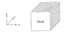
- (A) is a schematic diagram of an orthogonal coordinate system and each tomographic image when x, y, z are respectively changed.
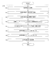
- 3 is a flowchart showing a flow of a series of tomographic images according to Embodiment 1. It is a schematic diagram when an element image is acquired by dividing one tomographic image into 1024 groups. It is a schematic diagram when various patterns of ring artifacts are artificially added to a normal tomographic image. 10 is a flowchart showing a flow of a series of tomographic images according to Embodiment 2.
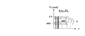
- (A), (b) is the schematic diagram which showed the relationship between each tomographic image and artifact when transforming from a rectangular coordinate system to a polar coordinate system.
- 10 is a flowchart showing a flow of a series of tomographic images according to Embodiment 3.
- (A), (b) is the schematic diagram which showed the relationship between each tomographic image and artifact when transforming from a rectangular coordinate system to a polar coordinate system when a region is divided into four. It is a schematic diagram of a polar coordinate system when the divided
- (A)-(c) is a schematic diagram for explaining generation of ring artifacts in a CT image.
- FIG. 1 is a schematic configuration diagram and a block diagram of an X-ray CT apparatus according to each embodiment including Embodiments 2 and 3 to be described later
- FIG. 2 is a schematic diagram for explaining acquisition related to each tomographic image
- FIG. 3 is a schematic diagram of the orthogonal coordinate system and each tomographic image when x, y, and z are changed.
- an X-ray CT apparatus will be described as an example of a tomography apparatus, and a CT image will be described as an example of a tomographic image.
- the body axis of the subject M is z, and the direction is perpendicular to the paper surface. Further, as shown in FIG. 1, the x axis and the y axis are taken.
- the X-ray CT apparatus according to the first embodiment including the second and third embodiments to be described later performs an X-ray directed toward the subject M and the top plate 1 on which the subject M is placed. And an X-ray detection array 4 for detecting X-rays transmitted through the subject M.
- the X-ray tube 2 is configured to emit fan-shaped X-rays.
- the X-ray tube 2 irradiates a cone-shaped X-ray beam that spreads along the body axis z direction.
- the X-ray detection element 3 is configured as a cell in channel units, and the X-ray detection array 4 is configured by arranging these in a ring shape.
- the X-ray detection array 4 is configured by arranging the X-ray detection elements 3 in parallel along the body axis z direction.
- an FPD in which the X-ray detection elements 3 are two-dimensionally arranged on a flat panel is used as the X-ray detection array 4.
- the X-ray tube 2 corresponds to the irradiation means in this invention, and the X-ray detection array 4 corresponds to the detection means in this invention.
- the X-ray CT apparatus includes a rotation drive unit 5 that rotates an imaging system including the X-ray tube 2 and the X-ray detection array 4 around the body axis z of the subject M.
- the rotation drive unit 5 is constituted by a motor, a rotation belt, etc., not shown.
- the rotation drive unit 5 rotates the rotation belt by rotating the motor, and rotates the gantry (not shown) by rotating the rotation belt.
- the X-ray tube 2 and the X-ray detection array 4 arranged in the figure are rotated in the direction of the arrow in the figure or in the opposite direction with the X-ray detection array 4 facing each other.
- the rotation drive unit 5 corresponds to the rotation means in this invention.
- the X-ray CT apparatus collects data obtained by the X-ray detection array 4 as projection data and a high-voltage generator 6 that applies a tube current or a high-voltage tube voltage to the X-ray tube 2.
- a collecting unit (DAS) 7, an image processing unit 8 for performing various processes on the projection data collected by the data collecting unit 7, a controller 9 for controlling each part of the X-ray CT apparatus, and a controller 9 is provided with an input unit 10 for inputting to the output unit 9, an output unit 11 for outputting various data sent through the controller 9, and a memory unit 12 for writing and storing various data sent through the controller 9.
- the image processing unit 8 corresponds to the image processing apparatus in the present invention, and also corresponds to the image processing means in the present invention.
- the controller 9 includes a central processing unit (CPU).
- the input unit 10 sends data and commands input by the operator to the controller 9.
- the input unit 10 includes a pointing device represented by a mouse, a keyboard, a joystick, a trackball, a touch panel, and the like.
- the output unit 11 includes a display unit represented by a monitor, a printer, and the like.
- the memory unit 12 includes a storage medium represented by ROM (Read-only Memory), RAM (Random-Access Memory), and the like.
- ROM Read-only Memory
- RAM Random-Access Memory
- the data collected by the data collection unit 7 and various data processed by the image processing unit 8 are written and stored in the RAM, and as necessary.
- Read from RAM The ROM stores in advance programs for performing various types of tomography, and the controller 9 executes the programs to perform tomography according to the programs.
- the data collection unit 7 and the image processing unit 8 send a program stored in a ROM of a storage medium represented by the memory unit 12 or the like described above, or a command input by a pointing device represented by the input unit 10 or the like to the controller 9. It is realized by executing.
- the image processing unit 8 reconstructs the projection data collected by the data collecting unit 7 to obtain a tomographic image (here, a CT image), a tomographic image, a pixel group including a ring artifact, A division unit 8b that divides the pixel group that does not include a ring artifact and a pixel group processing unit 8c that performs predetermined processing relating to correction only on the pixel group that includes the ring artifact are provided.
- a tomographic image here, a CT image
- a division unit 8b that divides the pixel group that does not include a ring artifact
- a pixel group processing unit 8c that performs predetermined processing relating to correction only on the pixel group that includes
- the dividing unit 8b corresponds to the dividing unit in the present invention
- the pixel group processing unit 8c corresponds to the pixel group processing unit in the present invention.
- the reconstruction processing unit 8a performs a reconstruction process based on the projection data to obtain a tomographic image.
- the reconstruction processing may be performed using a well-known filtered back projection (FBP: “Filtered” Back Projection) (also called “filtered back projection method”).
- FBP filtered back projection
- the tomographic image thus obtained is obtained by rotating the X-ray tube 2 and the X-ray detection array 4 around the axis of the body axis z of the subject M, that is, rotating in the x and y planes in FIG. Since it is the obtained data, the tomographic plane is the x, y plane. Further, each pixel value of the tomographic image is assumed to be F (x, y).
- the tomographic image F (x, y) obtained by taking the x, y, and z axes as shown in FIG. That is, an axial image is obtained, and as shown in FIG. 2, an axial image is obtained in the body axis z direction for each slice (ie, slice).
- the tomographic image F (x, y) is an axial image by taking the x, y, and z axes as shown in FIG. 1, but as shown in FIG. 2 is changed to y, y in FIG. 1 is changed to z, and z in FIGS.
- the tomographic image F (x, y) is coronally cut.
- the image may be a coronal image.
- x in FIGS. 1 and 2 is changed to z
- y in FIGS. 1 is changed to x
- z in FIG. 1 and FIG. 2 is changed to y
- the tomographic image F (x, y) may be a sagittal image, that is, a sagittal image.
- the tomographic image obtained as an axial image may be converted into a coronal image or a sagittal image.
- the X-ray tube 2 and the X-ray detection array 4 are rotated around the body axis z of the subject M (that is, in the x and y planes in FIG. 1). Ring artifacts appear on the axial image. Therefore, considering that the ring artifact is reliably removed, the tomographic image F (x, y) is preferably an axial image.
- the tomographic image obtained as an axial image is not converted to a coronal image or a sagittal image, but remains as an axial image, and the pixels that contain ring artifacts as shown below. It is preferable to divide into groups and pixel groups that do not contain ring artifacts.
- FIG. 4 is a flowchart showing a series of tomographic flows according to the first embodiment
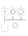
- FIG. 5 is a schematic diagram when an element image is acquired by dividing one tomographic image into 1024 groups.
- FIG. 6 is a schematic diagram when various patterns of ring artifacts are artificially added to a normal tomographic image.
- Step S1 Dividing the tomographic image into ⁇ groups
- the dividing unit 8b includes the ring artifact by performing the feature amount analysis of the ring artifact on the tomographic image F (x, y).
- the pixel group is divided into a pixel group that does not include a ring artifact.
- an independent component analysis ICA
- the image component corresponding to the ring artifact and the image component not corresponding to the ring artifact are separated into the image group including the ring artifact and the image group not including the ring artifact.
- the basis function A j is composed of F i (x, y) of N element pixels, and can be handled as a vector composed of N elements.
- An element image F i (x, y) composed of N elements can also be handled as a vector composed of N elements, and ⁇ tomographic images F (x, y) are ⁇ element images.
- F i (x, y) are ⁇ element images.
- ⁇ 10 a tomographic image F (x, y) having 512 ⁇ 512 pixels vertically and horizontally
- N 256
- ⁇ x 32
- ⁇ y 32
- ⁇ / ⁇ 32
- An element image F i (x, y) composed of 256 pixels can also be handled as a vector composed of 256 elements, and 10 tomographic images F (x, y) are 10240 element images.
- F i (x, y) an element image F i (x, y) composed of 256 pixels is obtained by dividing one tomographic image F (x, y) into 1024 groups. Further, the ten tomographic images F (x, y) are divided into 10240 groups to obtain an element image F i (x, y) composed of 256 pixels.
- Step S2 Expansion of Element Image with Basis Function
- the following relational expression (1) is established between each element image F i (x, y) and the basis function A j .
- the basis function A j satisfying the above equation (1) or the above equation (2) can be obtained by applying the above-described independent component analysis (ICA).
- ICA independent component analysis
- a specific method of calculating the basis function A j the above-mentioned Non-Patent Document 1 (by Chen Nobu, “Independent Component Analysis (1) —Cocktail Party Effect”), Journal of Japanese Society for Medical Image Engineering, 2003, Vol. 21, 1 No., p. 81-85).
- the above formula (1) or the above formula (2) corresponds to the formula (A) in the present invention.
- Step S3 Obtaining an image component corresponding to a ring artifact Of the basis functions A j expanded by the above expression (1) or (2), a basis function A h corresponding to a ring artifact (where 1 ⁇ h ⁇ N, the number of corresponding h is one or more), and the component s hi corresponding to the selected basis function A h is set as the image component corresponding to the ring artifact described above.
- the basis function A h corresponding to the ring artifact is not limited to one, and a plurality of basis functions A h exist.
- each tomographic image from the X-ray detector array having an X-ray detector array and abnormal cell e.g. consisting of only normal cells was calculated, respectively of seeking image components corresponding to the tomographic image may be performed by obtaining image components s hi corresponding to the abnormal X-ray detector array (i.e. ring artifacts).
- the value of the specific cell of the sinogram acquired with an X-ray detection array consisting only of normal cells is multiplied by, for example, 0.99 (this corresponds to reducing the sensitivity of the specific cell to 99%), and then the tomographic image is obtained.
- the image component s hi corresponding to the ring artifact can be obtained by calculation.
- the element image s hi * A h including the basis function A h corresponding to the ring artifact and the component s hi corresponding thereto is an image corresponding to the ring artifact. It becomes a pixel group including a component, that is, a ring artifact.
- the element image s ji * A j composed of the remaining unselected basis functions A j and the component s ji corresponding thereto is an image component that does not correspond to the ring artifact, that is, a pixel group that does not include the ring artifact. Therefore, by performing the steps S1 to S3, the pixel group including the ring artifact and the pixel group including no ring artifact are divided.
- the above-described division unit 8b (see FIG. 1) performs the steps S1 to S3.
- Step S4 Replace the component with “0” (correction process)
- step S4 not only correction processing that is replaced with “0” in step S4, but also filter processing for correction is performed. Absent. As described above, this means only that a predetermined process related to correction is not performed on a pixel group that does not include (ring) artifacts. Therefore, for predetermined processing other than correction (for example, correction of scale other than pixel value to luminance, correction processing other than artifact removal (for example, lag correction, gain correction, etc.)), the processing is applied to pixels that do not include (ring) artifacts. You may give to a group.
- the correction processing in step S4 is performed by the above-described pixel group processing unit 8c (see FIG. 1).
- a feature value analysis of ring artifacts (independent component analysis (ICA) in the first embodiment) is performed on a tomographic image, and a pixel group including the ring artifacts is detected.
- the ring artifact is divided into pixel groups that do not include ring artifacts, and predetermined processing relating to correction (processing that is replaced with “0” in the first embodiment) is performed only on the pixel groups that include the ring artifacts described above.
- a correction process is performed to remove.
- a predetermined process related to correction is performed only on a pixel group including a ring artifact, and a predetermined process related to correction is not performed on a pixel group including no ring artifact. Therefore, a pixel group including no ring artifact is included.
- the original normal tomographic image composed of the above is not subjected to filter processing for correction, etc., and artifacts due to the filter do not occur, and there are almost no side effects due to the filter, such as a decrease in image resolution. do not do.
- artifacts here, ring artifacts
- the image processing unit 8 and the X-ray CT apparatus including the image processing unit 8 according to the first embodiment the X-ray tube 2 that irradiates the subject M with X-rays and the X-ray that has passed through the subject M are detected.
- the X-ray detection array 4 is provided, and the tomographic image of the subject M regarding the X-rays obtained by the X-ray detection array 4 is processed by the image processing unit 8 to capture a tomographic image.
- the image processing unit 8 performs a ring artifact feature amount analysis (independent component analysis (ICA) in the first embodiment) on a tomographic image, and thereby a pixel group including the ring artifact and a pixel group not including the ring artifact.
- ICA independent component analysis
- a pixel group processing unit 8c that performs predetermined processing relating to correction (processing to replace “0” in the first embodiment) only on the pixel group including the ring artifact described above. Then, a correction process for removing the ring artifact is performed. In this way, a predetermined process related to correction is performed only on a pixel group including a ring artifact, and a predetermined process related to correction is not performed on a pixel group including no ring artifact. Therefore, a pixel group including no ring artifact is included.
- the artifact (here, the ring artifact) can be stably removed without causing any side effects due to a filter or the like such as a decrease in image resolution. Further, by removing artifacts stably, a good tomographic image can be obtained, and as a result, good imaging can be performed.
- the X-ray tube 2 and the X-ray detection array 4 are provided with a rotation drive unit 5 that rotates around the body axis z of the subject M.
- a rotation drive unit 5 that rotates around the body axis z of the subject M.
- the tomographic image is useful when the X-ray tube 2 and the X-ray detection array 4 are rotated around the body axis z of the subject M (ie, a CT image). It is.
- the imaging system including the X-ray tube 2 and the X-ray detection array 4 is rotated around the axis of the body axis z of the subject M so that the artifact is a ring artifact on the CT image. Appears as
- independent component analysis is adopted as the feature amount analysis.
- ICA independent component analysis
- Example 1 including Example 2 described later, predetermined processing relating to correction is performed only on the pixel group including the artifact by deleting the image component shi corresponding to the ring artifact.
- the basis function A h corresponding to the ring artifact (where 1 ⁇ h ⁇ N, the number of corresponding h is one or plural.
- the component s hi corresponding to the selected basis function A h is selected as the image component corresponding to the ring artifact.
- a correction process is performed on each element image F i (x, y) in which the image component s hi corresponding to the ring artifact is deleted by replacing the component s hi with “0”.
- the number of basis functions A h corresponding to a ring artifact is not necessarily one, and there may be a basis function A h corresponding to a plurality of artifacts.
- the ring artifact can be removed by replacing the component s hi with “0”.
- FIG. 7 is a flowchart showing a series of tomographic flows according to the second embodiment
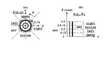
- FIG. 8 is a schematic diagram showing the relationship between each tomographic image and artifact when converted from the orthogonal coordinate system to the polar coordinate system.
- the X-ray CT apparatus according to the second embodiment has the same configuration as that of the first embodiment described above, the description thereof is omitted.
- steps common to the above-described first embodiment are denoted by the same reference numerals, description thereof is omitted, and only differences are described.
- Step T1 Conversion to Polar Coordinate System
- the dividing unit 8b (see FIG. 1) converts the tomographic image F (x, y) on the orthogonal coordinates of the orthogonal coordinate system x, y in FIG. b)
- the image is converted into an image F (r, ⁇ ) on the polar coordinates of the polar coordinate system r, ⁇ in FIG.
- a CT image is employed as the tomographic image (x, y), and therefore the tomographic image F (x, y) is represented by the polar coordinate system r.
- the ring artifact ART on the tomographic image F (x, y) shown in FIG. 8 (a) is converted into the image F shown in FIG. 8 (b). It is converted to a linear artifact ART on (r, ⁇ ).
- Step S1 The tomographic image is divided into ⁇ groups.
- the image to be divided is the tomographic image F (x, y) in the first embodiment, whereas the second embodiment.
- Step S2 Expansion of Element Image with Basis Function
- the following relational expression (3) is established between each element image F i (r, ⁇ ) and the basis function A j .
- Step T2 Obtaining Image Component Corresponding to Linear Artifact Among Basis Functions A j developed by Equation (3) above, Basis Function A h corresponding to Linear Artifact (where 1 ⁇ h ⁇ N, corresponding h And the component s hi corresponding to the selected basis function A h is set as the image component corresponding to the above-mentioned straight line artifact. Similar to the first embodiment described above, even in the case of the straight line artifact as in the second embodiment, the number of the basis functions A h corresponding to the straight line artifact is not limited to one, and a plurality of basis functions A h exist. To do. Since the method for obtaining the image component corresponding to the straight line artifact (that is, the component s hi corresponding to the selected basis function A h ) is the same as that in the first embodiment, the description thereof is omitted.
- the element image s hi * A h including the basis function A h corresponding to the straight line artifact and the component s hi corresponding thereto is an image corresponding to the straight line artifact.
- the pixel group includes linear artifacts on the component, that is, polar coordinates, and the pixel group includes ring artifacts on the orthogonal coordinates.
- the element image s ji * A j composed of the remaining unselected basis function A j and the component s ji corresponding thereto is an image component that does not correspond to the linear artifact, that is, a pixel group that does not include the linear artifact on the polar coordinates, orthogonal In terms of coordinates, the pixel group does not include ring artifacts. Therefore, by performing the steps T1, S1, S2, and T2, the pixel group including the ring artifact and the pixel group not including the ring artifact are divided (on the orthogonal coordinates).
- the dividing unit 8b (see FIG. 1) performs the steps T1, S1, S2, and T2.
- Step S4 Replace the component with “0” (correction process)
- the target image component to be replaced with “0” is the tomographic image F (x, y) in the first embodiment, whereas the image F (r) in the second embodiment. , ⁇ ), except that it is the same as that of the first embodiment, and a description thereof will be omitted.
- the correction processing in step S4 is performed by the above-described pixel group processing unit 8c (see FIG. 1).
- Step S5 Arranging Element Images
- the element image was the element image F i (x, y) in the first embodiment, whereas in the second embodiment, the element image F i (r, r Except for ⁇ ), it is the same as the first embodiment.
- Step T3 Inverse transformation into Cartesian coordinate system
- the image F (r, ⁇ ) from which the linear artifact has been removed in Step S5 is inversely transformed into a tomographic image F (x, y) on the Cartesian coordinate system x, y.
- a tomographic image F (x, y) from which ring artifacts have been removed is obtained.
- a predetermined process (this book) related to correction is performed only on the pixel group including the ring artifact.
- the actual correction target is subjected to the image component s hi ) corresponding to the linear artifact that has been converted into polar coordinates, and the predetermined processing related to the correction is not performed on the pixel group that does not include the ring artifact.
- artifacts here, ring artifacts
- the ring artifact on the tomographic image F (x, y) is converted by converting the tomographic image F (x, y) into the image F (r, ⁇ ) on the polar coordinate system r, ⁇ .
- a tomographic image F (x, y) from which ring artifacts have been removed is obtained.
- the straight line is a pattern in two directions (x, y). It is easy to detect as a feature, and ring artifacts tend to be difficult to detect as a feature.
- the straight line in the second embodiment is detected as features more than the ring in the first embodiment. It has the effect of being easy.
- FIG. 9 is a flowchart showing a series of tomographic flows according to the third embodiment
- FIG. 10 is a diagram of each tomographic image and artifact when the region is converted from a quadrature coordinate system to a polar coordinate system when the region is divided into four
- FIG. 11 is a schematic diagram showing the relationship
- FIG. 11 is a schematic diagram of a polar coordinate system when the divided regions overlap (overlap).
- the X-ray CT apparatus according to the third embodiment has the same configuration as that of the first and second embodiments, and a description thereof will be omitted.
- steps common to the first and second embodiments are denoted by the same reference numerals, description thereof is omitted, and only differences are described.
- Step T1 Conversion to Polar Coordinate System Since this step T1 is the same as that of the second embodiment, the description thereof is omitted.
- the tomographic image F (x, y) is converted into an image F (r, ⁇ ) on the polar coordinates of the polar coordinate system r, ⁇ .
- the ring artifact ART on the tomographic image F (x, y) shown in FIG. 10A is converted into the linear artifact ART on the image F (r, ⁇ ) shown in FIG. 10B. .
- Step S1 The tomographic image is divided into ⁇ groups. Since this step S1 is the same as that of the second embodiment, the description thereof is omitted.
- Step S2 Expansion of Element Image with Basis Function Since this step S2 is the same as that of the second embodiment, the description thereof is omitted. Expansion is performed with the basis function A j by the above equation (3) described in the second embodiment.
- Step T2 Obtaining Image Component Corresponding to Linear Artifact Among Basis Functions A j developed by Equation (3) above, Basis Function A h corresponding to Linear Artifact (where 1 ⁇ h ⁇ N, corresponding h
- the component s hi corresponding to the selected basis function A h is used as the image component corresponding to the linear artifact described above.
- the element image s hi * A h including the selected basis function A h and the component s hi corresponding to the selected basis function A h is set as an image component corresponding to the linear artifact.
- the component s hi corresponding to the selected basis function A h is not set to “0” as in the first and second embodiments, but the component is left as it is. Conversely, the component s ji corresponding to the unselected basis function A j is set to “0”.
- An element image F h (r, ⁇ ) composed of s hi * A h is obtained.
- the element image F h (r, ⁇ ) composed of s hi * A h is also a pixel group including straight line artifacts, and is regarded as an image composed of straight line artifact components.
- the element image F j (r, ⁇ ) composed of s ji * A j is also a pixel group that does not include a straight line artifact, and is
- the dividing unit 8b (see FIG. 1) performs the steps T1, S1, S2, and T2.
- Step U1 Smoothing filter processing (correction processing) for the component A smoothing (smoothing) filter is applied to the element image s hi * A h composed of the basis function A h selected in step T2 and the component s hi corresponding thereto, that is, the image component corresponding to the linear artifact. That is, the correction process is performed on the element image F h (r, ⁇ ) composed of s hi * A h related to the smoothing described above.
- M is not particularly limited, and any number of divisions can be selected by arbitrarily designating 1, 2, 3,...
- segmented in the polar coordinate system may overlap.
- the image F hk (r, ⁇ ) is a discontinuous function when viewed from ⁇
- the image F hk is integrated by integration in the above equation (4), but the image F hk is continuous as viewed from ⁇ .
- (R, ⁇ ) is interpolated or approximated, and the continuous interpolated image F hk (r, ⁇ ) or continuous approximated function is integrated as shown in the following equation (5):
- a one-dimensional profile function P k (r) integrated with ⁇ may be obtained.
- P k (r) ′ is obtained by applying a smoothing filter for r to the one-dimensional profile function P k (r) obtained by the above expression (4) or (5).
- This smoothing filter may be used averaging of P k (r) pressurizing th power average (arithmetic mean) and P k (r) the (geometric mean).
- the smoothing filter that is normally used for example, a Gaussian filter, a uniform weight smoothing filter, a median filter, etc.
- the above expression (6) corresponds to the expression (C) in this invention.
- the above expression (7) corresponds to the expression (D) in this invention.
- Step T3 Inverse transformation to Cartesian coordinate system
- This Step T3 is the same as in the second embodiment. That is, the image F (r, ⁇ ) from which the linear artifact has been removed in step U3 is inversely transformed into a tomographic image F (x, y) on the orthogonal coordinates of the orthogonal coordinate system x, y. By performing inverse transformation in this way, a tomographic image F (x, y) from which ring artifacts have been removed is obtained.
- a predetermined process related to correction is performed only on a pixel group that includes ring artifacts.
- an actual correction target is an image component s hi corresponding to a linear artifact that has been subjected to polar transformation
- a predetermined process related to correction is performed on a pixel group that does not include a ring artifact.
- a smoothing (smoothing) filter is applied to the pixel group including the ring artifact, so that only a predetermined pixel group including the ring artifact is corrected. It has been processed. Compared with the methods of the first and second embodiments that eliminate the image components corresponding to the ring artifacts, side effects due to filters and the like such as a reduction in image resolution with respect to the original normal tomographic image can be further suppressed.
- the basis function A h corresponding to linear artifacts also includes a little of the original CT image components (components excluding the artifact components) other than the artifact components.
- the component of the original normal tomographic image (here, the CT image) is also deleted.
- N is set to a large value, for example, 256 or more, the image quality of the corrected image is gradually improved, but the amount of calculation becomes enormous, making it difficult to actually use it.
- such a problem does not occur because the smoothing filter is used.
- a smoothing (smoothing) filter when a smoothing (smoothing) filter is applied to a pixel group including a ring artifact, independent component analysis is used as a feature amount analysis in the same manner as in the first and second embodiments.
- independent component analysis is used as a feature amount analysis in the same manner as in the first and second embodiments.
- the pixel group including the ring artifact and the pixel group not including the ring artifact are separated. It is divided.
- the above-described smoothing filter is applied to the image component corresponding to the ring artifact (actually, it is smoothed after being converted into the polar coordinate system.
- a predetermined process related to correction is performed only on the pixel group including the ring artifact.
- a smoothing filter to an image component corresponding to a ring artifact (a linear artifact in a polar coordinate system)
- conversion to a polar coordinate system and inverse conversion to an orthogonal coordinate system are performed.
- a basis function A h corresponding to a linear artifact (where 1 ⁇ h ⁇ N, the number of corresponding h is one or more) is selected. Then, the element image s hi * A h composed of the selected basis function A h and the component s hi corresponding thereto is set as an image component corresponding to the straight line artifact.
- a correction process is applied to the element image F h (r, ⁇ ) composed of s hi * A h in which a smoothing filter is applied to the image component to smooth the image component corresponding to the linear artifact.
- the tomographic image F (x, y) from which the ring artifact is removed is obtained by inversely transforming the image F (r, ⁇ ) into the tomographic image F (x, y) on the orthogonal coordinates of the orthogonal coordinate system x, y. .
- a profile function P k (r) integrated with ⁇ is obtained for each image F hk (r, ⁇ ).
- P k (r) ′ is obtained.
- the image F hk (r, ⁇ ) is substituted into the right side in the above equation (6) or the above equation (7) and is corrected by obtaining the left side.
- the present invention is not limited to the above embodiment, and can be modified as follows.
- the X-ray CT apparatus is described as an example of the tomography apparatus, but the tomography apparatus is not limited to the X-ray CT apparatus.
- the X-ray tube 2 and the flat panel X-ray detector (FPD) 30 are translated in the opposite directions along the body axis z direction of the subject M to perform tomography.
- the present invention may be applied to an apparatus or an apparatus that performs tomography by precessing the X-ray tube 2 / FPD 30 around the axis of the axis V orthogonal to the body axis z of the subject M. Good.
- the axis V may be parallel to the x-axis or y-axis in the figure, and is not particularly limited as long as it is orthogonal to the body axis.
- the processing in each embodiment described above is performed on the tomographic images obtained by these tomographic imaging.
- X-rays have been described as examples.
- nuclear medicine diagnosis apparatuses represented by PET (PositronsiEmission Tomography) and SPECT (Single Photon Emission CT), that is, ECT (Emission Computed).
- the detection means in the present invention detects radiation other than X-rays (gamma rays in the case of a PET apparatus) such as a Tomography apparatus, and the tomographic image of the subject relating to the radiation obtained by the detection means
- the processing in each embodiment described above may be performed.
- the radiation represented by X-rays and the like has been described as an example.
- the light obtained by the detection means when the detection means in the present invention detects light other than the radiation.
- the processing in each embodiment described above may be performed on the tomographic image of the subject.
- the irradiation means (X-ray tube in each embodiment) according to the present invention is provided has been described as an example, but the irradiation means is not necessarily provided.
- a radiopharmaceutical is administered into the body of the subject, and the radiation generated from the subject (for example, ⁇ rays, ⁇ rays, ⁇ rays, etc.) is detected by the detection means of the present invention.
- the present invention may be applied to an apparatus for obtaining a tomographic image.
- the nuclear medicine diagnosis apparatus may be applied to the case where the absorption correction is performed by providing an irradiation unit represented by an external radiation source that irradiates the same type of radiation as the radiopharmaceutical.
- the processing in each embodiment described above is performed on the tomographic image after the absorption correction.
- an X-ray tube has been described as an example of the irradiating means in the present invention.
- radiation or light other than X-rays is used.
- the irradiation unit may be configured accordingly.
- the irradiation means may be an LED (light-emitting diode) or a YAG laser that irradiates laser light.
- the X-ray detection element is configured as a cell for each channel as the detection means in the present invention, and the X-ray detection array configured by arranging them in parallel has been described as an example.
- the detection means may be constituted by an X-ray detection element alone, the detection means may be constituted by an image intensifier, an X-ray film, or the like of the above-described modifications (2) to (4).
- detection may be performed according to radiation or light other than X-rays.
- the detection means may be a photodiode or the like.
- the CT image is taken as an example of the tomographic image, but a tomographic image other than the CT image as in the above-described modified examples (1) to (4) may be used.
- the CT image is obtained by irradiating means (X-ray tube in each embodiment) and detecting means (X in each embodiment) around the body axis of the subject.
- the image was obtained by rotating the line detection array), but a CT image may be obtained by rotating the subject itself around the axis of the body axis, or the subject may be obtained around the axis of the body axis.
- the CT image may be obtained by rotating the irradiation means in the present invention and the detection means in the present invention around the axis of the body axis. Therefore, the specific form of rotation is not particularly limited as long as the irradiation unit and the detection unit rotate relatively around the body axis of the subject.
- a tomography apparatus typified by an X-ray CT apparatus or the like has been described as an example.
- the present invention may be applied to a single image processing apparatus (an image processing unit in each embodiment) excluding means (an X-ray detection array in each embodiment). Therefore, a tomographic image obtained from a tomographic apparatus that is an external apparatus may be transferred to an image processing apparatus, and the processing in each of the above-described embodiments may be performed on the tomographic image by this image processing apparatus.
- the independent component analysis has been described as an example of the feature amount analysis.
- the feature amount analysis is normally performed, for example, a wavelet transform or the like may be used.
- it is not limited to independent component analysis.
- the feature amount analysis of the artifact is performed to divide the pixel group including the artifact into the pixel group not including the artifact, and correct only the pixel group including the artifact described above.
- the above formula (C) (the above (6) in the third embodiment) is assumed without assuming the technical idea.
- the equation (C) ′ is modified to the following equation (C) ′, or the above equation (D) (the above equation (7) in the third embodiment) is modified to the following equation (D) ′ to apply a smoothing filter to the tomographic image. May be.
- a profile function P k (r) integrated by ⁇ is obtained, and a smoothing filter is applied to r for the profile function P k (r), whereby P k ( r) ′ is obtained, and the image F k (r, ⁇ ) is corrected by substituting the right side in the following formula (C) ′ or the following (D) ′ formula to obtain the left side.
- F k (r, ⁇ ) F k (r, ⁇ ) * P k (r) ′ / P k (r) (C) ′
- F k (r, ⁇ ) F k (r, ⁇ ) ⁇ (P k (r) ⁇ P k (r) ′) (D) ′
Landscapes
- Engineering & Computer Science (AREA)
- Health & Medical Sciences (AREA)
- Life Sciences & Earth Sciences (AREA)
- Physics & Mathematics (AREA)
- Medical Informatics (AREA)
- Pathology (AREA)
- Biomedical Technology (AREA)
- Biophysics (AREA)
- High Energy & Nuclear Physics (AREA)
- Theoretical Computer Science (AREA)
- Nuclear Medicine, Radiotherapy & Molecular Imaging (AREA)
- Optics & Photonics (AREA)
- General Physics & Mathematics (AREA)
- Radiology & Medical Imaging (AREA)
- Computer Vision & Pattern Recognition (AREA)
- Heart & Thoracic Surgery (AREA)
- Molecular Biology (AREA)
- Surgery (AREA)
- Animal Behavior & Ethology (AREA)
- General Health & Medical Sciences (AREA)
- Public Health (AREA)
- Veterinary Medicine (AREA)
- Apparatus For Radiation Diagnosis (AREA)
- Image Processing (AREA)
Abstract
Priority Applications (4)
| Application Number | Priority Date | Filing Date | Title |
|---|---|---|---|
| JP2009548845A JP5023281B2 (ja) | 2008-01-11 | 2008-01-11 | 画像処理方法、その装置並びに断層撮影装置 |
| US12/812,223 US8520974B2 (en) | 2008-01-11 | 2008-01-11 | Image processing method, an apparatus therefor and a tomographic apparatus for removing artifacts from a sectional image |
| PCT/JP2008/050266 WO2009087777A1 (fr) | 2008-01-11 | 2008-01-11 | Procédé de traitement d'image, son dispositif et dispositif de laminagraphie |
| CN2008801243075A CN101909525B (zh) | 2008-01-11 | 2008-01-11 | 图像处理方法、装置以及断层摄影装置 |
Applications Claiming Priority (1)
| Application Number | Priority Date | Filing Date | Title |
|---|---|---|---|
| PCT/JP2008/050266 WO2009087777A1 (fr) | 2008-01-11 | 2008-01-11 | Procédé de traitement d'image, son dispositif et dispositif de laminagraphie |
Publications (1)
| Publication Number | Publication Date |
|---|---|
| WO2009087777A1 true WO2009087777A1 (fr) | 2009-07-16 |
Family
ID=40852901
Family Applications (1)
| Application Number | Title | Priority Date | Filing Date |
|---|---|---|---|
| PCT/JP2008/050266 WO2009087777A1 (fr) | 2008-01-11 | 2008-01-11 | Procédé de traitement d'image, son dispositif et dispositif de laminagraphie |
Country Status (4)
| Country | Link |
|---|---|
| US (1) | US8520974B2 (fr) |
| JP (1) | JP5023281B2 (fr) |
| CN (1) | CN101909525B (fr) |
| WO (1) | WO2009087777A1 (fr) |
Cited By (3)
| Publication number | Priority date | Publication date | Assignee | Title |
|---|---|---|---|---|
| KR101431646B1 (ko) | 2013-02-12 | 2014-08-20 | 주식회사 쎄크 | 데이터처리장치, 데이터처리방법 및 컴퓨터 판독가능 기록매체 |
| EP2604187A4 (fr) * | 2010-07-14 | 2016-09-07 | Univ Tohoku | Dispositif de traitement de signal, programme de traitement de signal et support d'enregistrement lisible par ordinateur ayant un programme de traitement de signal enregistré sur celui-ci |
| KR101982941B1 (ko) * | 2017-12-18 | 2019-08-28 | 연세대학교 원주산학협력단 | 퍼지 신경망을 이용한 ct 영상의 허상 제거 방법 및 장치 |
Families Citing this family (20)
| Publication number | Priority date | Publication date | Assignee | Title |
|---|---|---|---|---|
| EP2108328B2 (fr) * | 2008-04-09 | 2020-08-26 | Brainlab AG | Procédé de commande basée sur l'image pour appareils médicaux |
| CN102014755B (zh) * | 2008-05-01 | 2013-02-13 | 皇家飞利浦电子股份有限公司 | 辐射源和/或探测器定位系统 |
| US8705827B2 (en) * | 2011-04-15 | 2014-04-22 | Georgia Tech Research Corporation | Scatter correction methods |
| GB201112359D0 (en) | 2011-07-19 | 2011-08-31 | Univ Antwerpen | Filter for tomographic reconstruction |
| US8929507B2 (en) * | 2011-10-19 | 2015-01-06 | Kabushiki Kaisha Toshiba | Method and system for substantially reducing ring artifact based upon ring statistics |
| JP6036122B2 (ja) * | 2012-02-02 | 2016-11-30 | セイコーエプソン株式会社 | 脈波測定装置及びプログラム |
| WO2013124777A1 (fr) * | 2012-02-22 | 2013-08-29 | Koninklijke Philips N.V. | Procédé et système de réduction d'artéfacts localisés dans des données d'imagerie |
| US9704223B2 (en) * | 2014-06-10 | 2017-07-11 | Toshiba Medical Systems Corporation | Method and system for substantially reducing cone beam artifacts based upon adaptive scaling factor in circular computer tomography (CT) |
| IT201700050472A1 (it) * | 2017-05-10 | 2018-11-10 | Rs Life360 S R L | Metodo per la realizzazione di immagini panoramiche a 360° da visualizzare in modo continuo da supporto bidimensionale su una superficie riflettente cilindrica o conica che simula la visione reale. |
| WO2019060298A1 (fr) | 2017-09-19 | 2019-03-28 | Neuroenhancement Lab, LLC | Procédé et appareil de neuro-activation |
| US11717686B2 (en) | 2017-12-04 | 2023-08-08 | Neuroenhancement Lab, LLC | Method and apparatus for neuroenhancement to facilitate learning and performance |
| US11478603B2 (en) | 2017-12-31 | 2022-10-25 | Neuroenhancement Lab, LLC | Method and apparatus for neuroenhancement to enhance emotional response |
| JP7210880B2 (ja) * | 2018-01-25 | 2023-01-24 | 株式会社島津製作所 | 骨密度測定装置および骨密度撮影方法 |
| US11364361B2 (en) | 2018-04-20 | 2022-06-21 | Neuroenhancement Lab, LLC | System and method for inducing sleep by transplanting mental states |
| CN109064441B (zh) * | 2018-06-19 | 2020-07-28 | 深圳市华星光电半导体显示技术有限公司 | 基于独立成分自适应选择的Mura侦测方法 |
| WO2020056418A1 (fr) | 2018-09-14 | 2020-03-19 | Neuroenhancement Lab, LLC | Système et procédé d'amélioration du sommeil |
| CN110111318B (zh) * | 2019-04-30 | 2021-06-29 | 上海联影医疗科技股份有限公司 | 一种环形伪影的检测方法和系统 |
| CN110889878B (zh) * | 2019-11-08 | 2023-06-09 | 湖北科技学院 | 结合图像平滑处理的ct图像环形伪影抑制方法 |
| CN111053568B (zh) * | 2019-12-30 | 2021-10-08 | 苏州瑞派宁科技有限公司 | Ct图像中环形伪影的校正方法、装置及计算机存储介质 |
| CN114066889B (zh) * | 2022-01-12 | 2022-04-29 | 广州永士达医疗科技有限责任公司 | 一种oct主机的成像质量检测方法及装置 |
Citations (5)
| Publication number | Priority date | Publication date | Assignee | Title |
|---|---|---|---|---|
| JPH07143979A (ja) * | 1993-07-16 | 1995-06-06 | General Electric Co <Ge> | 断層撮影画像中のアーチファクトを低減する方法および装置 |
| JPH09187452A (ja) * | 1995-11-13 | 1997-07-22 | General Electric Co <Ge> | 螺旋走査において収集される投影走査データから発生される像データにおけるアーティファクトを減少させる方法及び装置 |
| JP2002133399A (ja) * | 2000-10-23 | 2002-05-10 | Hitachi Medical Corp | 画像処理装置及びそれを用いたx線ct装置 |
| JP2007080268A (ja) * | 2005-09-15 | 2007-03-29 | Ge Medical Systems Global Technology Co Llc | 画像処理方法およびx線ct装置 |
| WO2007046172A1 (fr) * | 2005-10-20 | 2007-04-26 | Niigata University | Procédé de traitement d’image à résonance magnétique et processeur d’image à résonance magnétique |
Family Cites Families (8)
| Publication number | Priority date | Publication date | Assignee | Title |
|---|---|---|---|---|
| DE69717780T2 (de) | 1996-07-30 | 2003-07-17 | Koninkl Philips Electronics Nv | Korrektur von ringförmigen bildartefakten |
| DE19736242A1 (de) * | 1997-08-20 | 1999-02-25 | Siemens Ag | Verfahren für einen Computertomographen zur Nachverarbeitung eines Schnittbildes und nach diesem Verfahren arbeitender Computertomograph |
| JPH11126218A (ja) | 1997-10-22 | 1999-05-11 | Mitsubishi Electric Corp | 論理シミュレーション装置 |
| US6801646B1 (en) * | 2001-07-19 | 2004-10-05 | Virtualscopics, Llc | System and method for reducing or eliminating streak artifacts and illumination inhomogeneity in CT imaging |
| US7519207B2 (en) * | 2004-11-19 | 2009-04-14 | Carestream Health, Inc. | Detection and correction method for radiograph orientation |
| US8073252B2 (en) * | 2006-06-09 | 2011-12-06 | Siemens Corporation | Sparse volume segmentation for 3D scans |
| US7680240B2 (en) * | 2007-03-30 | 2010-03-16 | General Electric Company | Iterative reconstruction of tomographic image data method and system |
| JP5136478B2 (ja) * | 2009-03-17 | 2013-02-06 | 株式会社島津製作所 | 放射線撮影装置 |
-
2008
- 2008-01-11 CN CN2008801243075A patent/CN101909525B/zh not_active Expired - Fee Related
- 2008-01-11 US US12/812,223 patent/US8520974B2/en not_active Expired - Fee Related
- 2008-01-11 JP JP2009548845A patent/JP5023281B2/ja active Active
- 2008-01-11 WO PCT/JP2008/050266 patent/WO2009087777A1/fr active Application Filing
Patent Citations (5)
| Publication number | Priority date | Publication date | Assignee | Title |
|---|---|---|---|---|
| JPH07143979A (ja) * | 1993-07-16 | 1995-06-06 | General Electric Co <Ge> | 断層撮影画像中のアーチファクトを低減する方法および装置 |
| JPH09187452A (ja) * | 1995-11-13 | 1997-07-22 | General Electric Co <Ge> | 螺旋走査において収集される投影走査データから発生される像データにおけるアーティファクトを減少させる方法及び装置 |
| JP2002133399A (ja) * | 2000-10-23 | 2002-05-10 | Hitachi Medical Corp | 画像処理装置及びそれを用いたx線ct装置 |
| JP2007080268A (ja) * | 2005-09-15 | 2007-03-29 | Ge Medical Systems Global Technology Co Llc | 画像処理方法およびx線ct装置 |
| WO2007046172A1 (fr) * | 2005-10-20 | 2007-04-26 | Niigata University | Procédé de traitement d’image à résonance magnétique et processeur d’image à résonance magnétique |
Cited By (3)
| Publication number | Priority date | Publication date | Assignee | Title |
|---|---|---|---|---|
| EP2604187A4 (fr) * | 2010-07-14 | 2016-09-07 | Univ Tohoku | Dispositif de traitement de signal, programme de traitement de signal et support d'enregistrement lisible par ordinateur ayant un programme de traitement de signal enregistré sur celui-ci |
| KR101431646B1 (ko) | 2013-02-12 | 2014-08-20 | 주식회사 쎄크 | 데이터처리장치, 데이터처리방법 및 컴퓨터 판독가능 기록매체 |
| KR101982941B1 (ko) * | 2017-12-18 | 2019-08-28 | 연세대학교 원주산학협력단 | 퍼지 신경망을 이용한 ct 영상의 허상 제거 방법 및 장치 |
Also Published As
| Publication number | Publication date |
|---|---|
| US20100284599A1 (en) | 2010-11-11 |
| US8520974B2 (en) | 2013-08-27 |
| JP5023281B2 (ja) | 2012-09-12 |
| CN101909525A (zh) | 2010-12-08 |
| CN101909525B (zh) | 2013-06-05 |
| JPWO2009087777A1 (ja) | 2011-05-26 |
Similar Documents
| Publication | Publication Date | Title |
|---|---|---|
| JP5023281B2 (ja) | 画像処理方法、その装置並びに断層撮影装置 | |
| JP4414420B2 (ja) | X線断層撮影装置およびアーチファクトの低減方法 | |
| Abella et al. | Software architecture for multi-bed FDK-based reconstruction in X-ray CT scanners | |
| JP4611168B2 (ja) | 画像再構成方法、およびx線ct装置 | |
| JP6109524B2 (ja) | X線コンピュータ断層撮影装置及び画像補正方法 | |
| JP5670050B2 (ja) | 画像再構成装置および画像再構成方法 | |
| CN102768759B (zh) | 一种术中ct图像射束硬化伪影校正方法及装置 | |
| US8938108B2 (en) | Method for artifact reduction in cone-beam CT images | |
| EP2469472A1 (fr) | Procédé et appareil de reconstruction d'image de tomodensitométrie (tdm) | |
| JP5406063B2 (ja) | 再構成演算装置、再構成演算方法、及びx線ct装置 | |
| US7529335B2 (en) | Voxel-driven spiral reconstruction for cone-beam computer tomography | |
| JP2014144274A (ja) | X線コンピュータ断層撮影装置及び医用画像処理装置 | |
| JP2013085960A (ja) | 画像再構成方法及び画像再構成システム | |
| JP6176828B2 (ja) | 画像再構成装置、画像再構成方法およびx線コンピュータ断層撮影装置 | |
| US9704223B2 (en) | Method and system for substantially reducing cone beam artifacts based upon adaptive scaling factor in circular computer tomography (CT) | |
| US20120294417A1 (en) | Image domain based noise reduction for low dose computed tomography fluoroscopy | |
| JP5329204B2 (ja) | X線ct装置 | |
| JP5317612B2 (ja) | 断層像処理装置、x線ct装置およびプログラム | |
| JP2003024322A5 (fr) | ||
| JP6615531B2 (ja) | X線コンピュータ断層撮影装置及び医用画像処理装置 | |
| JP5493072B2 (ja) | Ct装置、ct装置における画像再構成方法、及び電子回路部品 | |
| JPWO2007096936A1 (ja) | 断層撮影装置および演算処理プログラム | |
| JP2018143574A (ja) | X線ct装置及び画像処理方法 | |
| US8620052B2 (en) | Projection truncation processing for CBCT | |
| US11055825B2 (en) | Medical image processing device and X-ray CT device provided with same, and medical image processing method |
Legal Events
| Date | Code | Title | Description |
|---|---|---|---|
| WWE | Wipo information: entry into national phase |
Ref document number: 200880124307.5 Country of ref document: CN |
|
| 121 | Ep: the epo has been informed by wipo that ep was designated in this application |
Ref document number: 08703130 Country of ref document: EP Kind code of ref document: A1 |
|
| ENP | Entry into the national phase |
Ref document number: 2009548845 Country of ref document: JP Kind code of ref document: A |
|
| WWE | Wipo information: entry into national phase |
Ref document number: 12812223 Country of ref document: US |
|
| NENP | Non-entry into the national phase |
Ref country code: DE |
|
| 122 | Ep: pct application non-entry in european phase |
Ref document number: 08703130 Country of ref document: EP Kind code of ref document: A1 |