WO2009084262A1 - 変速装置 - Google Patents
変速装置 Download PDFInfo
- Publication number
- WO2009084262A1 WO2009084262A1 PCT/JP2008/063358 JP2008063358W WO2009084262A1 WO 2009084262 A1 WO2009084262 A1 WO 2009084262A1 JP 2008063358 W JP2008063358 W JP 2008063358W WO 2009084262 A1 WO2009084262 A1 WO 2009084262A1
- Authority
- WO
- WIPO (PCT)
- Prior art keywords
- clutch
- spline
- fitted
- peripheral surface
- drum
- Prior art date
- Legal status (The legal status is an assumption and is not a legal conclusion. Google has not performed a legal analysis and makes no representation as to the accuracy of the status listed.)
- Ceased
Links
Images



Classifications
-
- F—MECHANICAL ENGINEERING; LIGHTING; HEATING; WEAPONS; BLASTING
- F16—ENGINEERING ELEMENTS AND UNITS; GENERAL MEASURES FOR PRODUCING AND MAINTAINING EFFECTIVE FUNCTIONING OF MACHINES OR INSTALLATIONS; THERMAL INSULATION IN GENERAL
- F16D—COUPLINGS FOR TRANSMITTING ROTATION; CLUTCHES; BRAKES
- F16D25/00—Fluid-actuated clutches
- F16D25/10—Clutch systems with a plurality of fluid-actuated clutches
-
- F—MECHANICAL ENGINEERING; LIGHTING; HEATING; WEAPONS; BLASTING
- F16—ENGINEERING ELEMENTS AND UNITS; GENERAL MEASURES FOR PRODUCING AND MAINTAINING EFFECTIVE FUNCTIONING OF MACHINES OR INSTALLATIONS; THERMAL INSULATION IN GENERAL
- F16D—COUPLINGS FOR TRANSMITTING ROTATION; CLUTCHES; BRAKES
- F16D13/00—Friction clutches
- F16D13/58—Details
- F16D13/60—Clutching elements
- F16D13/64—Clutch-plates; Clutch-lamellae
- F16D13/68—Attachments of plates or lamellae to their supports
- F16D13/683—Attachments of plates or lamellae to their supports for clutches with multiple lamellae
-
- F—MECHANICAL ENGINEERING; LIGHTING; HEATING; WEAPONS; BLASTING
- F16—ENGINEERING ELEMENTS AND UNITS; GENERAL MEASURES FOR PRODUCING AND MAINTAINING EFFECTIVE FUNCTIONING OF MACHINES OR INSTALLATIONS; THERMAL INSULATION IN GENERAL
- F16D—COUPLINGS FOR TRANSMITTING ROTATION; CLUTCHES; BRAKES
- F16D25/00—Fluid-actuated clutches
- F16D25/06—Fluid-actuated clutches in which the fluid actuates a piston incorporated in, i.e. rotating with the clutch
- F16D25/062—Fluid-actuated clutches in which the fluid actuates a piston incorporated in, i.e. rotating with the clutch the clutch having friction surfaces
- F16D25/063—Fluid-actuated clutches in which the fluid actuates a piston incorporated in, i.e. rotating with the clutch the clutch having friction surfaces with clutch members exclusively moving axially
- F16D25/0635—Fluid-actuated clutches in which the fluid actuates a piston incorporated in, i.e. rotating with the clutch the clutch having friction surfaces with clutch members exclusively moving axially with flat friction surfaces, e.g. discs
- F16D25/0638—Fluid-actuated clutches in which the fluid actuates a piston incorporated in, i.e. rotating with the clutch the clutch having friction surfaces with clutch members exclusively moving axially with flat friction surfaces, e.g. discs with more than two discs, e.g. multiple lamellae
-
- F—MECHANICAL ENGINEERING; LIGHTING; HEATING; WEAPONS; BLASTING
- F16—ENGINEERING ELEMENTS AND UNITS; GENERAL MEASURES FOR PRODUCING AND MAINTAINING EFFECTIVE FUNCTIONING OF MACHINES OR INSTALLATIONS; THERMAL INSULATION IN GENERAL
- F16H—GEARING
- F16H3/00—Toothed gearings for conveying rotary motion with variable gear ratio or for reversing rotary motion
- F16H3/44—Toothed gearings for conveying rotary motion with variable gear ratio or for reversing rotary motion using gears having orbital motion
- F16H3/62—Gearings having three or more central gears
- F16H3/66—Gearings having three or more central gears composed of a number of gear trains without drive passing from one train to another
- F16H3/663—Gearings having three or more central gears composed of a number of gear trains without drive passing from one train to another with conveying rotary motion between axially spaced orbital gears, e.g. a stepped orbital gear or Ravigneaux
-
- F—MECHANICAL ENGINEERING; LIGHTING; HEATING; WEAPONS; BLASTING
- F16—ENGINEERING ELEMENTS AND UNITS; GENERAL MEASURES FOR PRODUCING AND MAINTAINING EFFECTIVE FUNCTIONING OF MACHINES OR INSTALLATIONS; THERMAL INSULATION IN GENERAL
- F16H—GEARING
- F16H3/00—Toothed gearings for conveying rotary motion with variable gear ratio or for reversing rotary motion
- F16H3/44—Toothed gearings for conveying rotary motion with variable gear ratio or for reversing rotary motion using gears having orbital motion
- F16H3/62—Gearings having three or more central gears
- F16H3/66—Gearings having three or more central gears composed of a number of gear trains without drive passing from one train to another
- F16H3/666—Gearings having three or more central gears composed of a number of gear trains without drive passing from one train to another with intermeshing orbital gears
-
- F—MECHANICAL ENGINEERING; LIGHTING; HEATING; WEAPONS; BLASTING
- F16—ENGINEERING ELEMENTS AND UNITS; GENERAL MEASURES FOR PRODUCING AND MAINTAINING EFFECTIVE FUNCTIONING OF MACHINES OR INSTALLATIONS; THERMAL INSULATION IN GENERAL
- F16D—COUPLINGS FOR TRANSMITTING ROTATION; CLUTCHES; BRAKES
- F16D48/00—External control of clutches
- F16D48/02—Control by fluid pressure
- F16D2048/0212—Details of pistons for primary or secondary cylinders especially adapted for fluid control
-
- F—MECHANICAL ENGINEERING; LIGHTING; HEATING; WEAPONS; BLASTING
- F16—ENGINEERING ELEMENTS AND UNITS; GENERAL MEASURES FOR PRODUCING AND MAINTAINING EFFECTIVE FUNCTIONING OF MACHINES OR INSTALLATIONS; THERMAL INSULATION IN GENERAL
- F16H—GEARING
- F16H2200/00—Transmissions for multiple ratios
- F16H2200/003—Transmissions for multiple ratios characterised by the number of forward speeds
- F16H2200/006—Transmissions for multiple ratios characterised by the number of forward speeds the gear ratios comprising eight forward speeds
-
- F—MECHANICAL ENGINEERING; LIGHTING; HEATING; WEAPONS; BLASTING
- F16—ENGINEERING ELEMENTS AND UNITS; GENERAL MEASURES FOR PRODUCING AND MAINTAINING EFFECTIVE FUNCTIONING OF MACHINES OR INSTALLATIONS; THERMAL INSULATION IN GENERAL
- F16H—GEARING
- F16H2200/00—Transmissions for multiple ratios
- F16H2200/0082—Transmissions for multiple ratios characterised by the number of reverse speeds
- F16H2200/0086—Transmissions for multiple ratios characterised by the number of reverse speeds the gear ratios comprising two reverse speeds
-
- F—MECHANICAL ENGINEERING; LIGHTING; HEATING; WEAPONS; BLASTING
- F16—ENGINEERING ELEMENTS AND UNITS; GENERAL MEASURES FOR PRODUCING AND MAINTAINING EFFECTIVE FUNCTIONING OF MACHINES OR INSTALLATIONS; THERMAL INSULATION IN GENERAL
- F16H—GEARING
- F16H2200/00—Transmissions for multiple ratios
- F16H2200/20—Transmissions using gears with orbital motion
- F16H2200/2002—Transmissions using gears with orbital motion characterised by the number of sets of orbital gears
- F16H2200/2007—Transmissions using gears with orbital motion characterised by the number of sets of orbital gears with two sets of orbital gears
-
- F—MECHANICAL ENGINEERING; LIGHTING; HEATING; WEAPONS; BLASTING
- F16—ENGINEERING ELEMENTS AND UNITS; GENERAL MEASURES FOR PRODUCING AND MAINTAINING EFFECTIVE FUNCTIONING OF MACHINES OR INSTALLATIONS; THERMAL INSULATION IN GENERAL
- F16H—GEARING
- F16H2200/00—Transmissions for multiple ratios
- F16H2200/20—Transmissions using gears with orbital motion
- F16H2200/203—Transmissions using gears with orbital motion characterised by the engaging friction means not of the freewheel type, e.g. friction clutches or brakes
- F16H2200/2046—Transmissions using gears with orbital motion characterised by the engaging friction means not of the freewheel type, e.g. friction clutches or brakes with six engaging means
-
- F—MECHANICAL ENGINEERING; LIGHTING; HEATING; WEAPONS; BLASTING
- F16—ENGINEERING ELEMENTS AND UNITS; GENERAL MEASURES FOR PRODUCING AND MAINTAINING EFFECTIVE FUNCTIONING OF MACHINES OR INSTALLATIONS; THERMAL INSULATION IN GENERAL
- F16H—GEARING
- F16H2200/00—Transmissions for multiple ratios
- F16H2200/20—Transmissions using gears with orbital motion
- F16H2200/203—Transmissions using gears with orbital motion characterised by the engaging friction means not of the freewheel type, e.g. friction clutches or brakes
- F16H2200/2048—Transmissions using gears with orbital motion characterised by the engaging friction means not of the freewheel type, e.g. friction clutches or brakes with seven engaging means
Definitions
- the present invention relates to a transmission, and more particularly to a transmission capable of changing a gear position by switching engagement states of a plurality of clutches.
- the two clutch drums are arranged in two layers on a concentric circle, so that the two clutches can be accommodated in a compact manner and the entire device can be downsized.
- the method of arranging the clutch drums in two layers there is a restriction on the radial size of each clutch drum, and a necessary torque capacity (contact area of the clutch plate) must be ensured within this restriction.
- the total length (length in the axial direction) of the device becomes large.
- the main purpose of the transmission of the present invention is to reduce the size of the device while ensuring the necessary torque capacity.
- the transmission of the present invention employs the following means in order to achieve the main object described above.
- the transmission of the present invention is A transmission that shifts the power input to the input shaft with a shift stage that can be changed by switching the engagement state of the plurality of clutches, and outputs the power to the output shaft,
- An annular clutch plate is spline-fitted to the inner peripheral surface of the first clutch drum, and the clutch plate can be pressed by sliding in the axial direction.
- a first clutch in which the formed clutch piston is disposed; The outer circumference is concentrically disposed in the clutch piston of the first clutch, and the outer circumferential surface is spline fitted to the inner circumferential surface of the clutch piston and the annular clutch plate is spline fitted to the inner circumferential surface.
- a second clutch having a second clutch drum in which splines are formed on the inner and outer peripheral surfaces so that the surface spline teeth become the spline grooves on the inner peripheral surface; It is a summary to provide.
- the first clutch drum is provided, and an annular clutch plate is spline-fitted on the inner peripheral surface of the first clutch drum, and the clutch plate can be pressed by sliding in the axial direction.
- a first clutch in which a clutch piston having a spline formed on the peripheral surface is disposed, and a concentric circle disposed in the clutch piston of the first clutch, and the outer peripheral surface is spline-fitted to the inner peripheral surface of the clutch piston.
- a second clutch drum having splines formed on the inner and outer peripheral surfaces so that the spline teeth on the outer peripheral surface become spline grooves on the inner peripheral surface so that the annular clutch plate is spline-fitted on the inner peripheral surface.
- the “clutch” includes a normal clutch that connects two rotating systems, and also includes a brake that connects one rotating system to a stationary system such as a case.
- the clutch piston has an outer peripheral surface that is spline-fitted with the inner peripheral surface of the first clutch drum, and an inner peripheral surface that is spline-fitted with the outer peripheral surface of the second clutch drum.
- splines may be formed on the inner and outer peripheral surfaces so that the spline teeth on the outer peripheral surface become the spline grooves on the inner peripheral surface. In this way, the diameter of the clutch plate that is spline-fitted to the inner peripheral surface of the second clutch drum can be increased.
- the spline between the inner peripheral surface of the clutch piston and the outer peripheral surface of the second clutch drum is formed by the inner peripheral surface of the first clutch drum and the outer peripheral surface of the clutch piston.
- the spline groove and the spline teeth may be formed so as to be fitted with a spatial margin in the circumferential direction as compared with the spline fitting. By so doing, it is possible to prevent the second clutch drum from hindering the axial movement of the clutch piston.
- the first clutch drum and the second clutch drum are integrally rotated by spline fitting at a connecting portion different from the portion that is spline-fitted via the clutch piston. It can also be made possible to be connected.
- the first clutch drum has a first member formed with spline teeth that are spline fitted to the clutch piston, and a second member formed with spline teeth that are spline fitted to the second clutch drum.
- the second clutch drum has a third member formed with spline teeth that are spline-fitted to the clutch piston, and a spline tooth that is spline-fitted to the first clutch drum.
- a fourth member, and the connection between the first member and the second member and the connection between the third member and the fourth member are the first clutch drum and the second member.
- the clutch drums are spline-fitted through the clutch piston and spline teeth are phase-matched so that they are spline-fitted at the connecting portion. It may be those formed by sintering. By doing so, it is possible to make the phase alignment of the spline teeth easier.
- the transmission device includes four rotating elements, the first rotating element is connected to the clutch C1, the second rotating element is connected to the rotating shaft, and the third rotating element is connected to the output shaft.
- the fourth rotating element is composed of a first planetary gear mechanism fixed to the case via a one-way clutch and connected to the input shaft via a clutch C2, and three rotating elements.
- a second rotating element fixed to the case is connected to the rotating shaft via a clutch C3, and is connected to the first rotating element of the first planetary gear mechanism via the clutch C1.
- a second planetary gear mechanism having an element connected to the input shaft and connected to the rotary shaft via a clutch C4, and the rotary shaft is further fixed to the case via a brake B1,
- the fourth rotating element of the first planetary gear mechanism is further fixed to the case via a brake B2,
- the first clutch is the clutch C3
- the second clutch is the clutch C4. It can also be. If it carries out like this, size reduction of the whole apparatus can be achieved, ensuring the torque capacity of the required clutch C4.
- the second planetary gear mechanism is formed as a speed reducing mechanism that decelerates the power input to the third rotating element and outputs the reduced power to the third rotating element. It can also be. In this way, the torque capacity can be secured even in the clutch C4 that requires a relatively large torque capacity.
- the transmission may be an in-vehicle stepped transmission.
- the transmission may be a longitudinal transmission that is arranged vertically so that the input shaft and the output shaft are perpendicular to the axle. In this way, the effect of the present invention can be made more conspicuous in a longitudinal transmission that is particularly limited in size in the radial direction.
- FIG. 3 is an explanatory diagram showing an operation table of the transmission 20.
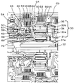
- FIG. 3 is a cross-sectional view showing a partial cross section of the transmission 20.
- FIG. 2 is a cross-sectional view showing a cross section in a state where two clutch drums 50 and 60 and a clutch piston 56 are assembled.
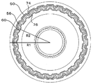
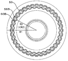
- FIG. FIG. 5 is a cross-sectional view showing the AA cross section of FIG. 4. It is sectional drawing of a comparative example.
- FIG. 1 is a configuration diagram showing an outline of the configuration of an automobile 10 equipped with a transmission 20 as an embodiment of the present invention.
- an automobile 10 according to an embodiment includes an engine 12 as an internal combustion engine that outputs power by explosive combustion of a hydrocarbon fuel such as gasoline and light oil, and a torque converter attached to a crankshaft 14 of the engine 12. 16 and an output shaft 24 is connected to the output side of the torque converter 16, and an output shaft 24 is connected to the drive wheels 19 a and 19 b via the differential gear 18 to shift and output the power input to the input shaft 22.
- a transmission 20 as a stepped transmission that transmits to the shaft 24.
- the vehicle 10 is configured as a front engine rear drive (FR) type vehicle, and the engine 22 is configured such that the crankshaft 14 of the engine 22 (the input shaft 22 and the output shaft 24 of the transmission 20) is orthogonal to the axle. And the transmission 20 are arranged vertically.
- FR front engine rear drive
- the torque converter 16 is interposed between the pump impeller 16a connected to the crankshaft 14 side of the engine 12, the turbine runner 16b connected to the input shaft 22 side of the transmission 20, and the pump impeller 16a and the turbine runner 16b. And a stator 16c for transmitting power between the crankshaft 14 of the engine 12 and the input shaft 22 of the transmission 20 with the amplification of torque through oil filled therein.
- the transmission 20 is configured as an 8-speed stepped transmission that is driven using hydraulic pressure from a hydraulic circuit (not shown), and includes a double pinion planetary gear mechanism 30, a Ravigneaux planetary gear mechanism 40, and four gears. Clutches C1, C2, C3, C4, two brakes B1, B2, and a one-way clutch F1 are provided.
- the double pinion type planetary gear mechanism 30 includes a sun gear 31 as an external gear, a ring gear 32 as an internal gear arranged concentrically with the sun gear 31, and a plurality of first pinion gears 33a meshing with the sun gear 31.
- the carrier 34 that meshes with the first pinion gear 33a and meshes with the ring gear 32, and couples the plurality of first pinion gears 33a and the plurality of second pinion gears 33b so as to rotate and revolve freely.
- the sun gear 31 is fixed to the case, the ring gear 32 is connected to the rotary shaft 36 via the clutch C3, and the carrier 34 is connected to the rotary shaft 36 via the clutch C4.
- the rotation shaft 36 can be freely or fixedly rotated by turning on and off the brake B1.
- the Ravigneaux planetary gear mechanism 40 includes two sun gears 41a and 41b as external gears, a ring gear 42 as an internal gear, a plurality of short pinion gears 43a meshing with the sun gear 41a, a sun gear 41b and a plurality of short pinion gears 43a.
- the sun gear 41a includes a plurality of long pinion gears 43b that mesh with the ring gear 42, and a carrier 44 that connects the plurality of short pinion gears 43a and the plurality of long pinion gears 43b to rotate and revolve, and the sun gear 41a holds the clutch C1.
- the sun gear 41b is connected to the rotating shaft 36
- the ring gear 42 is connected to the output shaft 24
- the carrier 44 is connected to the one-way clutch F1.
- One direction of rotation The regulated and release of the brake B2 via the clutch C2 while being freely or fix the rotation is connected to the input shaft 22.
- the transmission 20 is turned on / off of the clutches C1 to C4 (on is engaged and off is released) and brakes B1 and B2 are turned on and off (on is engaged and off is released).
- the state can be switched between forward 1st to 8th speed, reverse 1st speed, and 2nd speed and neutral.
- the neutral state can be formed by turning off the clutches C1 to C4 and the brakes B1 and B2.
- the state of the first forward speed can be formed by turning on the clutch C1 and turning off the clutches C2 to C4 and the brakes B1 and B2. In this state, a double pinion type is connected from the input shaft 22.
- the power input to the carrier 34 of the planetary gear mechanism 30 is decelerated by the fixing of the sun gear 31 and transmitted to the ring gear 32, and also input from the ring gear 32 to the sun gear 41a of the Ravigneaux type planetary gear mechanism 40 via the clutch C1.
- the power is decelerated by fixing the carrier 44 by the one-way clutch F1 and output to the ring gear 42, that is, the output shaft 24. Therefore, the power input to the input shaft 22 is decelerated with the largest reduction ratio and output to the output shaft 24. .
- the rotation of the carrier 44 is fixed in place of the one-way clutch F1 by turning on the brake B2 during engine braking.
- the second forward speed state can be formed by turning on the clutch C1 and the brake B1 and turning off the clutches C2 to C4 and the brake B2.
- a double pinion type planet is connected from the input shaft 22.
- the power input to the carrier 34 of the gear mechanism 30 is decelerated by the fixation of the sun gear 31, is transmitted to the ring gear 32, and is also input from the ring gear 32 to the sun gear 41a of the Ravigneaux planetary gear mechanism 40 via the clutch C1. Is decelerated by fixing the sun gear 41b by the brake B1 and is output to the ring gear 42, that is, the output shaft 24. Therefore, the power input to the input shaft 22 is decelerated with a reduction ratio slightly smaller than the first forward speed to the output shaft 24.
- the third forward speed state can be formed by turning on the clutches C1 and C3 and turning off the clutches C2 and C4 and the brakes B1 and B2.
- a double pinion type The power input to the carrier 34 of the planetary gear mechanism 30 is decelerated by the fixing of the sun gear 31 and transmitted to the ring gear 32, and also input from the ring gear 32 to the sun gear 41a of the Ravigneaux type planetary gear mechanism 40 via the clutch C1.
- the power input to the sun gear 41b via the clutch C3 is output to the ring gear 42, that is, the output shaft 24 without shifting, so the power input to the input shaft 22 has a slightly smaller reduction ratio than the second forward speed.
- the speed is reduced and output to the output shaft 24.
- the forward fourth speed state can be formed by turning on the clutches C1 and C4 and turning off the clutches C2 and C3 and the brakes B1 and B2.
- the double pinion type The power input to the carrier 34 of the planetary gear mechanism 30 is decelerated by the fixing of the sun gear 31 and transmitted to the ring gear 32, and also input from the ring gear 32 to the sun gear 41a of the Ravigneaux type planetary gear mechanism 40 via the clutch C1.
- the power is accelerated by the power output from the input shaft 22 to the sun gear 41b via the carrier 34 and the clutch C4 and is output to the ring gear 42, that is, the output shaft 24.
- the power input to the input shaft 22 is the forward 3
- the output is decelerated with a reduction ratio slightly smaller than the speed and output to the output shaft 24.
- the state of the fifth forward speed can be formed by turning on the clutches C1 and C2 and turning off the clutches C3 and C4 and the brakes B1 and B2. In this state, the double pinion type
- the power input to the carrier 34 of the planetary gear mechanism 30 is decelerated by the fixing of the sun gear 31 and transmitted to the ring gear 32, and also input from the ring gear 32 to the sun gear 41a of the Ravigneaux type planetary gear mechanism 40 via the clutch C1.
- the sixth forward speed state can be formed by turning on the clutches C2 and C4 and turning off the clutches C1 and C3 and the brakes B1 and B2. In this state, the input shaft 22 is connected via the clutch C4. Since it is connected to the sun gear 41b of the Ravigneaux type planetary gear mechanism 40 and also connected to the carrier 44 via the clutch C2, all the rotating elements of the Ravigneaux type planetary gear mechanism 40 rotate integrally with the input shaft 22.
- the input power is output to the output shaft 24 at a constant speed.
- the seventh forward speed state can be formed by turning on the clutches C2 and C3 and turning off the clutches C1 and C4 and the brakes B1 and B2.
- a double pinion type The power input to the carrier 34 of the planetary gear mechanism 30 is decelerated by the fixation of the sun gear 31 and transmitted to the ring gear 32 and is also output from the input shaft 22 to the carrier 44 of the Ravigneaux type planetary gear mechanism 40 via the clutch C2. Since the motive power is increased by the power input from the ring gear 32 to the sun gear 41b via the clutch C3 and output to the ring gear 42, that is, the output shaft 24, the power input to the input shaft 22 is slightly smaller than the constant speed.
- the speed is increased with a reduction ratio and output to the output shaft 24.
- the eighth forward speed state can be formed by turning on the clutch C2 and the brake B1 and turning off the clutches C1, C3, C4 and the brake B2. In this state, the clutch C2 is connected to the clutch C2.
- the power output to the carrier 44 of the Ravigneaux type planetary gear mechanism 40 via the speed is increased by fixing the sun gear 41b by the brake B1 and output to the ring gear 42, that is, the output shaft 24, and thus input to the input shaft 22.
- the power is increased with a reduction ratio slightly smaller than the seventh forward speed and output to the output shaft 24.
- the reverse first speed state can be formed by turning on the clutch C3 and the brake B2 and turning off the clutches C1, C2, C4 and the brake B1.
- the power input to the carrier 34 of the double-pinion planetary gear mechanism 30 is decelerated by the fixation of the sun gear 31 and transmitted to the ring gear 32, and from the ring gear 32 via the clutch C3, the sun gear 41b of the Ravigneaux planetary gear mechanism 40. Since the power input to the motor is reversely rotated by fixing the carrier 44 by the brake B2 and output to the ring gear 42, that is, the output shaft 24, the power input to the input shaft 22 is decelerated with a relatively large reduction ratio and reversely rotated. Is output to the output shaft 24 as power.
- the second reverse speed state can be formed by turning on the clutch C4 and the brake B2 and turning off the clutches C1 to C3 and the brake B1.
- the input shaft 22 is connected via the clutch C4.
- the power input to the sun gear 41b of the Ravigneaux planetary gear mechanism 40 is rotated reversely by fixing the carrier 44 by the brake B2 and output to the ring gear 42, that is, the output shaft 24. Therefore, the power input to the input shaft 22 is
- the motor is decelerated with a relatively small reduction ratio and is output to the output shaft 24 as reverse rotation power.
- FIG. 3 is a configuration diagram showing an outline of a partial configuration centering on the clutch C3 and the clutch C4 in the transmission 20 of the embodiment.
- the clutch C3 includes a clutch drum 50 fixed to the rotating shaft 36 (see FIG. 1), a clutch hub 54 fixed to the ring gear 32 of the double pinion planetary gear mechanism 30, and a clutch drum 50, as shown in the figure.
- a return spring 57 urged in the opposite direction to the clutch plates 53 and 55 side, and a spring retainer 58 as a spring receiver locked to the clutch drum 50 by a snap ring 59, are provided from a hydraulic circuit (not shown). Is used to slide the clutch piston 56 toward the clutch plates 53 and 55. Thereby engaging the clutch drum 50 and the clutch hub 54 by a frictional force acting between the clutch plates 53, 55 by pressing the clutch plates 53, 55 with.
- the clutch C4 is concentrically disposed in the clutch drum 50, and is connected to the clutch drum 50 so as to rotate integrally therewith, and a clutch hub 64 fixed to the carrier 34 of the double pinion planetary gear mechanism 30.
- a plurality of annular clutch plates 63, 65 alternately splined to the inner peripheral surface of the clutch drum 60 and the outer peripheral surface of the clutch hub 64; a clutch piston 66 slidable toward the clutch plates 63, 65;
- a return spring 67 that urges the clutch piston 66 in a direction opposite to the clutch plates 63 and 65 side, and a spring retainer 68 as a spring receiver locked to the clutch drum 50 by a snap ring 69, are provided from the hydraulic circuit.
- the clutch piston 66 is moved to the clutch plate
- the clutch drum 60 and the clutch hub 64 are engaged with each other by a frictional force acting between the clutch plates 63 and 65 by sliding to the side of the clutch plates 63 and 65 and sliding to the side of the clutch plates 63 and 65.
- the clutch drum 50 and the clutch drum 60 are rotatably supported by a cylindrical bush 70 attached to a sun gear shaft 31a connected to the sun gear 31 of the double pinion planetary gear mechanism 30.
- FIG. 4 is a cross-sectional view showing a cross section in a state where the two clutch drums 50 and 60 and the clutch piston 56 are assembled.
- the clutch drum 50 is configured such that a cylindrical drum member 51 and a base member 52 that forms the bottom of the clutch drum 50 are joined at a joining portion 51a using welding or the like.
- the drum member 51 houses a first housing portion 51b formed on the inner diameter of the value r1 so that the clutch C4 (clutch drum 60, clutch hub 64, clutch piston 66, etc.) can be housed, and the double pinion planetary gear mechanism 30.
- the second housing is formed with an inner diameter of a value r2 larger than the value r1 so that the clutch plates 53 and 55 can be accommodated between the ring gear 32 of the planetary gear mechanism 30 and the outer peripheral surface of the clutch hub 54 formed integrally.
- a portion 51c is formed.
- the base member 52 includes a flange portion 52a serving as a joint portion 51a whose outer peripheral edge is joined to the drum member 51, and a cylindrical boss portion 52b extending in the axial direction from the flange portion 52a.
- the clutch drum 60 is configured such that a bowl-shaped drum member 61 having an opening at the center of the bottom portion and a base member 62 connected to the base member 52 are joined at a joining portion 61a using welding or the like.
- the base member 62 includes a flange portion 62a serving as a joint portion 61a whose outer peripheral edge is joined to the opening of the drum member 61, and a cylindrical boss portion 62b extending in the axial direction from the flange portion 62a.
- a fitting portion 72 is formed for spline fitting so that the clutch drum 50 and the clutch drum 60 can rotate together. Yes.
- FIG. 5 is a cross-sectional view showing the AA cross section of FIG.
- the clutch piston 56 has splines formed on both the outer peripheral surface and the inner peripheral surface so that the spline teeth on the outer peripheral surface become the spline grooves on the inner peripheral surface.
- Splines are formed on both the outer peripheral surface and the inner peripheral surface so that the spline teeth on the surface become spline grooves on the inner peripheral surface.
- a fitting portion 74 capable of spline fitting is formed on the inner peripheral surface of the clutch drum 50 and the outer peripheral surface of the clutch piston 56, and the inner peripheral surface of the clutch piston 56 and the outer peripheral surface of the clutch drum 60 are A fitting portion 76 capable of spline fitting is formed.
- FIG. 6 shows a cross-sectional view of a comparative example in which the clutch piston 56B and the clutch drum 60B are not spline-fitted.
- the outer diameter is reduced by the amount that the spline teeth of the clutch drum 60B are not fitted into the clutch piston 56B (smaller than the value R2). Value R3).
- the clutch piston 56 and the clutch drum 60 are spline-fitted on the inner and outer peripheral surfaces so that the spline teeth on the outer peripheral surface become the spline grooves on the inner peripheral surface, and the two are spline-fitted.
- switching between the third forward speed and the fourth forward speed, switching between the sixth forward speed and the seventh forward speed, the first reverse speed, and the second reverse speed are performed.
- the fitting portion 74 is a clutch in which the groove width of the spline groove of the clutch drum 50 is fitted to the clutch drum 50 and the clutch piston 56 with a slight clearance in the circumferential direction. It is formed slightly larger than the tooth width of the spline teeth of the piston 56.
- the fitting portion 76 is a groove of a spline groove of the clutch piston 56 so that the clutch piston 56 and the clutch drum 60 are fitted with a margin in the circumferential direction as compared with the fitting portion 74.
- the width is formed to be sufficiently larger than the tooth width of the spline teeth of the clutch drum 60 fitted therein. Accordingly, the clutch drum 60 does not prevent the clutch piston 56 from sliding in the axial direction.
- the clutch piston 56 is spline-fitted by the clutch drum 50 and the fitting portion 74 to prevent rotation, but torque transmission between the clutch drum 50 and the clutch drum 60 is performed by the fitting portion 72 described above. No torque is transmitted via the clutch piston 56.
- the two clutch drums 50 and 60 are spline-fitted so as to be integrally connected by the fitting portion 72 and are also spline-fitted by the fitting portions 74 and 76 via the clutch piston 56. Therefore, the spline teeth in the fitting portion 72 and the spline teeth in the fitting portions 74 and 76 need to be phase-matched.
- the clutch drum 50 is created by forming splines at necessary portions of the drum member 51 and the base member 52, aligning the phases, and aligning the joining portion 51a with the drum member 51 and the base member 52.
- the drum member 51 and the base member 52 are fixed using a fixing jig that can be fixed, and the joining portion 51a is welded.
- the clutch drum 60 was created by the same method. The reason why the clutch drums 50 and 60 are constituted by the two members of the drum members 51 and 61 and the base members 52 and 62 is based on such a reason.
- the clutch drums 50 and 60 are arranged concentrically on the concentric circle, and the spline teeth on the outer peripheral surface of the clutch piston 56 and the clutch drum 60 become the spline grooves on the inner peripheral surface. Since the splines are formed on the inner and outer peripheral surfaces and the both are spline-fitted, the diameters (contact areas) of the clutch plates 63 and 65 that are fitted to the clutch drum 60 without increasing the size of the clutch drum 50 in the radial direction are set. A sufficient torque capacity can be secured by increasing the size. As a result, the number of clutch plates 63, 65 can be reduced, and the overall length (axial length) of the device can be reduced.
- the clutch drums 50 and 60 are arranged in layers on concentric circles, the mounting can be efficiently performed even when the clutch drums 50 and 60 are mounted on the FR type automobile 10 having a large restriction on the size in the radial direction.
- the fitting part 76 is formed so that the clutch piston 56 and the clutch drum 60 are fitted with a margin in the circumferential direction with respect to the fitting part 74, the clutch drum 56 is rotated even if the clutch piston 56 is slightly rotated in the circumferential direction. It is possible to prevent the clutch piston 56 from coming into contact with the clutch drum 60 and to prevent the clutch piston 56 from sliding.
- the clutch drum 50 and the clutch drum 60 are constituted by the two members of the drum members 51 and 61 and the base members 52 and 62, respectively, the clutch drum 50 and the clutch drum 60 are integrated by the fitting portion 72. It is possible to make the spline teeth phased more easily when the spline fitting is performed so as to be coupled to each other and the fitting portions 74 and 76 are spline fitted via the clutch piston 56.
- the clutch drum 50 and the clutch drum 60 corresponding to the clutch C3 and the clutch C4 are spline-fitted so that torque is transmitted by the fitting portion 72, and the clutch drum 50 and the clutch drum 60 are connected to each other.
- the outer clutch drum and the inner clutch are not used in a transmission that does not involve changing the two clutches arranged in layers. It is good also as what forms the transmission of the torque between drums.
- the inner clutch drum may be configured to also serve as a clutch piston for pressing a clutch plate attached to the outer clutch drum.
- the inner peripheral surface of the clutch drum 50 and the outer peripheral surface of the clutch piston 56 are spline-fitted, but the spline fitting may be omitted.
- a rotation prevention mechanism for preventing rotation of the clutch piston may be provided separately.
- the clutch drum 50 and the clutch drum 60 are configured by joining two members of the drum members 51 and 61 and the base members 52 and 62.
- Either or both of 60 may be constituted by three or more members, or may be constituted by a single member.
- a hydraulically driven 8-speed stepped transmission is used.
- the transmission is not limited to the 8-speed. It does not matter as having any shift stage such as a shift stage higher than the speed.
- the clutch C3 corresponds to a “first clutch”
- the clutch C4 corresponds to a “second clutch”.
- the drum member 51 corresponds to a “first member”
- the base member 52 corresponds to a “second member”
- the drum member 61 corresponds to a “third member”
- the base member 62 corresponds to a “first member”. 4 ".
- the correspondence between the main elements of the embodiment and the main elements of the invention described in the column of means for solving the problem is the same as that of the embodiment described in the column of means for solving the problem.
- the present invention can be used in the transmission manufacturing industry.
Landscapes
- Engineering & Computer Science (AREA)
- General Engineering & Computer Science (AREA)
- Mechanical Engineering (AREA)
- Structure Of Transmissions (AREA)
- Hydraulic Clutches, Magnetic Clutches, Fluid Clutches, And Fluid Joints (AREA)
Abstract
Description
複数のクラッチの係合状態を切り替えることにより変更可能な変速段をもって入力軸に入力された動力を変速して出力軸に出力する変速装置であって、
第1のクラッチドラムを有し、該第1のクラッチドラムの内周面に環状のクラッチプレートがスプライン嵌合されると共に軸方向にスライドして該クラッチプレートを押圧可能で内周面にスプラインが形成されたクラッチピストンが配置されてなる第1のクラッチと、
前記第1のクラッチのクラッチピストン内に同心円上に配置され外周面が前記クラッチピストンの内周面にスプライン嵌合されると共に内周面に環状のクラッチプレートがスプライン嵌合されるように前記外周面のスプライン歯が前記内周面のスプライン溝となるよう内外周面にスプラインが形成されてなる第2のクラッチドラムを有する第2のクラッチと、
を備えることを要旨とする。
3,65側にスライドさせてクラッチプレート63,65側に押し付けることによりクラッチプレート63,65間に作用する摩擦力によりクラッチドラム60とクラッチハブ64とを係合する。なお、クラッチドラム50とクラッチドラム60は、ダブルピニオン式の遊星歯車機構30のサンギヤ31に接続されたサンギヤ軸31aに取り付けられた円筒状のブッシュ70により回転自在に支持されている。
Claims (9)
- 複数のクラッチの係合状態を切り替えることにより変更可能な変速段をもって入力軸に入力された動力を変速して出力軸に出力する変速装置であって、
第1のクラッチドラムを有し、該第1のクラッチドラムの内周面に環状のクラッチプレートがスプライン嵌合されると共に軸方向にスライドして該クラッチプレートを押圧可能で内周面にスプラインが形成されたクラッチピストンが配置されてなる第1のクラッチと、
前記第1のクラッチのクラッチピストン内に同心円上に配置され外周面が前記クラッチピストンの内周面にスプライン嵌合されると共に内周面に環状のクラッチプレートがスプライン嵌合されるように前記外周面のスプライン歯が前記内周面のスプライン溝となるよう内外周面にスプラインが形成されてなる第2のクラッチドラムを有する第2のクラッチと、
を備える変速装置。 - 前記クラッチピストンは、外周面が前記第1のクラッチドラムの内周面とスプライン嵌合されると共に内周面が前記第2のクラッチドラムの外周面とスプライン嵌合されるように前記外周面のスプライン歯が前記内周面のスプライン溝となるよう内外周面にスプラインが形成されてなる請求項1記載の変速装置。
- 前記クラッチピストンの内周面と前記第2のクラッチドラムの外周面とのスプラインは、前記第1のクラッチドラムの内周面と前記クラッチピストンの外周面とのスプライン嵌合に比してスプライン溝とスプライン歯とが周方向に空間的な余裕をもって嵌合されるよう形成されてなる請求項2記載の変速装置。
- 前記第1のクラッチドラムと前記第2のクラッチドラムは、前記クラッチピストンを介してスプライン嵌合された部位とは異なる連結部位でスプライン嵌合により一体回転可能に連結されてなる請求項2または3記載の変速装置。
- 請求項4記載の変速装置であって、
前記第1のクラッチドラムは、前記クラッチピストンにスプライン嵌合するスプライン歯が形成された第1の部材と、前記第2のクラッチドラムにスプライン嵌合するスプライン歯が形成された第2の部材とからなり、
前記第2のクラッチドラムは、前記クラッチピストンにスプライン嵌合するスプライン歯が形成された第3の部材と、前記第1のクラッチドラムにスプライン嵌合するスプライン歯が形成された第4の部材とからなり、
前記第1の部材と前記第2の部材との連結と前記第3の部材と前記第4の部材との連結は、前記第1のクラッチドラムと前記第2のクラッチドラムとが前記クラッチピストンを介してスプライン嵌合すると共に前記連結部位でスプライン嵌合するようスプライン歯を位相合わせした状態で互いに連結されてなる
変速装置。 - 請求項1ないし5いずれか1項に記載の変速装置であって、
4つの回転要素からなり、第1の回転要素がクラッチC1に接続され第2の回転要素が回転軸に接続され第3の回転要素が前記出力軸に接続され第4の回転要素がワンウェイクラッチを介してケースに固定されると共にクラッチC2を介して前記入力軸に接続された第1の遊星歯車機構と、
3つの回転要素からなり、第1の回転要素がケースに固定され第2の回転要素がクラッチC3を介して前記回転軸に接続されると共に前記クラッチC1を介して前記第1の遊星歯車機構の前記第1の回転要素に接続され第3の回転要素が前記入力軸に接続されると共
にクラッチC4を介して前記回転軸に接続された第2の遊星歯車機構と、
を備え、
前記回転軸は、さらにブレーキB1を介してケースに固定され、
前記第1の遊星歯車機構の前記第4の回転要素は、さらにブレーキB2を介してケースに固定され、
前記第1のクラッチは、前記クラッチC3であり、
前記第2のクラッチは、前記クラッチC4である
変速装置。 - 前記第2の遊星歯車機構は、前記第3の回転要素に入力される動力を減速して前記第3の回転要素に出力する減速機構として形成されてなる請求項6記載の変速装置。
- 前記変速装置は、車載用の有段変速機である請求項1ないし7いずれか1項に記載の変速装置。
- 前記変速装置は、前記入力軸および前記出力軸が車軸に対して直交方向となるよう縦置きに配置される縦置き用変速機である請求項8記載の変速装置。
Priority Applications (2)
| Application Number | Priority Date | Filing Date | Title |
|---|---|---|---|
| CN2008800208939A CN101680497B (zh) | 2007-12-28 | 2008-07-25 | 变速装置 |
| DE112008001627T DE112008001627B4 (de) | 2007-12-28 | 2008-07-25 | Drehzahländerungsvorrichtung mit einer Vielzahl von Kupplungen |
Applications Claiming Priority (2)
| Application Number | Priority Date | Filing Date | Title |
|---|---|---|---|
| JP2007-338776 | 2007-12-28 | ||
| JP2007338776A JP5200532B2 (ja) | 2007-12-28 | 2007-12-28 | 変速装置 |
Publications (1)
| Publication Number | Publication Date |
|---|---|
| WO2009084262A1 true WO2009084262A1 (ja) | 2009-07-09 |
Family
ID=40799198
Family Applications (1)
| Application Number | Title | Priority Date | Filing Date |
|---|---|---|---|
| PCT/JP2008/063358 Ceased WO2009084262A1 (ja) | 2007-12-28 | 2008-07-25 | 変速装置 |
Country Status (5)
| Country | Link |
|---|---|
| US (1) | US7998011B2 (ja) |
| JP (1) | JP5200532B2 (ja) |
| CN (1) | CN101680497B (ja) |
| DE (1) | DE112008001627B4 (ja) |
| WO (1) | WO2009084262A1 (ja) |
Families Citing this family (10)
| Publication number | Priority date | Publication date | Assignee | Title |
|---|---|---|---|---|
| US8298122B2 (en) * | 2009-10-06 | 2012-10-30 | Ford Global Technologies, Llc | Control of parallel reaction brakes in a transmission |
| CN103244570B (zh) * | 2012-02-06 | 2017-10-17 | 博世汽车部件(长沙)有限公司 | 车辆起动机及其花键装置 |
| JP5693531B2 (ja) * | 2012-07-20 | 2015-04-01 | ジヤトコ株式会社 | 摩擦締結装置構造およびその摩擦板の組付け方法 |
| DE102013216747A1 (de) * | 2013-08-23 | 2015-02-26 | Volkswagen Aktiengesellschaft | Lamellenträger für eine Doppelkupplungsanordnung, Doppelkupplungsanordnung und Verfahren zum Herstellen von Lamellen dafür |
| CN104631031B (zh) * | 2015-02-15 | 2016-09-07 | 浙江三星机电股份有限公司 | 一种洗衣机减速离合器 |
| US9759273B2 (en) * | 2015-03-24 | 2017-09-12 | Precision International Automotive Products, Inc. | Piston |
| US9964183B2 (en) * | 2015-04-13 | 2018-05-08 | Ford Global Technologies, Llc | Transmission with high speed clutch hub |
| EP3636947A1 (en) * | 2018-10-10 | 2020-04-15 | MAGNA Powertrain (Changzhou) Co., Ltd. | Clutch housing |
| DE102019104074A1 (de) * | 2019-02-19 | 2020-08-20 | Schaeffler Technologies AG & Co. KG | Dreifachkupplung für achsparalleles Hybridmodul mit getriebeseitiger Ansteuerung von drei Kupplungen über Dreheinführung |
| JP7552274B2 (ja) * | 2020-11-13 | 2024-09-18 | マツダ株式会社 | 自動変速機 |
Citations (4)
| Publication number | Priority date | Publication date | Assignee | Title |
|---|---|---|---|---|
| JPS6252249A (ja) * | 1985-08-31 | 1987-03-06 | Mitsubishi Motors Corp | 遠心油圧相殺式クラツチ付き動力伝達装置 |
| JPH04262125A (ja) * | 1991-02-18 | 1992-09-17 | Mitsubishi Motors Corp | オートマチックトランスミッションにおけるクラッチ構造 |
| JP2003343598A (ja) * | 2002-05-30 | 2003-12-03 | Aisin Aw Co Ltd | 変速機の多重クラッチ装置 |
| JP2005207579A (ja) * | 2003-12-25 | 2005-08-04 | Aisin Aw Co Ltd | クラッチ用油圧サーボ |
Family Cites Families (6)
| Publication number | Priority date | Publication date | Assignee | Title |
|---|---|---|---|---|
| JP2655935B2 (ja) * | 1990-07-06 | 1997-09-24 | 本田技研工業株式会社 | 多重クラッチ構造およびこの多重クラッチ構造を用いた変速機 |
| JP2816768B2 (ja) * | 1990-12-17 | 1998-10-27 | アイシン・エィ・ダブリュ株式会社 | 自動変速機における油圧アクチュエータ装置 |
| JPH06137387A (ja) * | 1992-10-28 | 1994-05-17 | Honda Motor Co Ltd | 油圧式ダブルクラッチ |
| US20050167234A1 (en) | 2003-12-25 | 2005-08-04 | Aisin Aw Co., Ltd | Clutch-purpose hydraulic servo |
| JP4691932B2 (ja) * | 2004-09-17 | 2011-06-01 | トヨタ自動車株式会社 | 自動変速機のクラッチ装置 |
| JP4712535B2 (ja) * | 2005-05-20 | 2011-06-29 | アイシン・エィ・ダブリュ株式会社 | 自動変速機における連結構造 |
-
2007
- 2007-12-28 JP JP2007338776A patent/JP5200532B2/ja not_active Expired - Fee Related
-
2008
- 2008-07-25 DE DE112008001627T patent/DE112008001627B4/de not_active Expired - Fee Related
- 2008-07-25 WO PCT/JP2008/063358 patent/WO2009084262A1/ja not_active Ceased
- 2008-07-25 CN CN2008800208939A patent/CN101680497B/zh not_active Expired - Fee Related
- 2008-12-03 US US12/314,057 patent/US7998011B2/en not_active Expired - Fee Related
Patent Citations (4)
| Publication number | Priority date | Publication date | Assignee | Title |
|---|---|---|---|---|
| JPS6252249A (ja) * | 1985-08-31 | 1987-03-06 | Mitsubishi Motors Corp | 遠心油圧相殺式クラツチ付き動力伝達装置 |
| JPH04262125A (ja) * | 1991-02-18 | 1992-09-17 | Mitsubishi Motors Corp | オートマチックトランスミッションにおけるクラッチ構造 |
| JP2003343598A (ja) * | 2002-05-30 | 2003-12-03 | Aisin Aw Co Ltd | 変速機の多重クラッチ装置 |
| JP2005207579A (ja) * | 2003-12-25 | 2005-08-04 | Aisin Aw Co Ltd | クラッチ用油圧サーボ |
Also Published As
| Publication number | Publication date |
|---|---|
| JP5200532B2 (ja) | 2013-06-05 |
| US7998011B2 (en) | 2011-08-16 |
| CN101680497B (zh) | 2013-01-02 |
| US20090170652A1 (en) | 2009-07-02 |
| CN101680497A (zh) | 2010-03-24 |
| JP2009156457A (ja) | 2009-07-16 |
| DE112008001627T5 (de) | 2010-06-02 |
| DE112008001627B4 (de) | 2013-09-12 |
Similar Documents
| Publication | Publication Date | Title |
|---|---|---|
| JP5200532B2 (ja) | 変速装置 | |
| US9784345B2 (en) | Transmission device | |
| WO2010021152A1 (ja) | 自動変速機 | |
| JP6183467B2 (ja) | 多段変速機 | |
| US10041570B2 (en) | Power transmission device | |
| CN105899848A (zh) | 用于前进档/倒档行星齿轮组的多模式离合器行星齿轮组 | |
| WO2006059754A1 (ja) | 自動変速機 | |
| JP5445506B2 (ja) | 変速装置 | |
| JP5440543B2 (ja) | 変速装置 | |
| JP4372072B2 (ja) | 変速伝動装置 | |
| JP4729366B2 (ja) | 多段自動変速機用2連油圧クラッチ装置 | |
| JP2005113974A (ja) | 車輌用自動変速機 | |
| JP2007139065A (ja) | 自動変速機における圧油供給装置 | |
| JP6418302B2 (ja) | 変速装置 | |
| JP2004324753A (ja) | 自動変速機の動力伝達装置 | |
| JP4697082B2 (ja) | 自動変速機 | |
| JP2015105723A (ja) | 多段変速機 | |
| JP6156201B2 (ja) | 動力伝達装置 | |
| JPH02113151A (ja) | 自動変速機におけるクラッチ連動装置 | |
| JP2007092821A (ja) | 摩擦係合装置 | |
| JP2007040541A (ja) | 自動変速機 | |
| JP2016168976A (ja) | 車両用駆動装置 | |
| JP2012102750A (ja) | 変速装置 | |
| JP2009085358A (ja) | 自動変速機 |
Legal Events
| Date | Code | Title | Description |
|---|---|---|---|
| WWE | Wipo information: entry into national phase |
Ref document number: 200880020893.9 Country of ref document: CN |
|
| 121 | Ep: the epo has been informed by wipo that ep was designated in this application |
Ref document number: 08791602 Country of ref document: EP Kind code of ref document: A1 |
|
| WWE | Wipo information: entry into national phase |
Ref document number: 1120080016275 Country of ref document: DE |
|
| RET | De translation (de og part 6b) |
Ref document number: 112008001627 Country of ref document: DE Date of ref document: 20100602 Kind code of ref document: P |
|
| 122 | Ep: pct application non-entry in european phase |
Ref document number: 08791602 Country of ref document: EP Kind code of ref document: A1 |