WO2009084233A1 - Compresseur à vis - Google Patents
Compresseur à vis Download PDFInfo
- Publication number
- WO2009084233A1 WO2009084233A1 PCT/JP2008/004026 JP2008004026W WO2009084233A1 WO 2009084233 A1 WO2009084233 A1 WO 2009084233A1 JP 2008004026 W JP2008004026 W JP 2008004026W WO 2009084233 A1 WO2009084233 A1 WO 2009084233A1
- Authority
- WO
- WIPO (PCT)
- Prior art keywords
- port
- spiral groove
- screw rotor
- slide valve
- discharge
- Prior art date
Links
Images


Classifications
-
- F—MECHANICAL ENGINEERING; LIGHTING; HEATING; WEAPONS; BLASTING
- F04—POSITIVE - DISPLACEMENT MACHINES FOR LIQUIDS; PUMPS FOR LIQUIDS OR ELASTIC FLUIDS
- F04C—ROTARY-PISTON, OR OSCILLATING-PISTON, POSITIVE-DISPLACEMENT MACHINES FOR LIQUIDS; ROTARY-PISTON, OR OSCILLATING-PISTON, POSITIVE-DISPLACEMENT PUMPS
- F04C18/00—Rotary-piston pumps specially adapted for elastic fluids
- F04C18/48—Rotary-piston pumps with non-parallel axes of movement of co-operating members
- F04C18/50—Rotary-piston pumps with non-parallel axes of movement of co-operating members the axes being arranged at an angle of 90 degrees
- F04C18/52—Rotary-piston pumps with non-parallel axes of movement of co-operating members the axes being arranged at an angle of 90 degrees of intermeshing engagement type, i.e. with engagement of co-operating members similar to that of toothed gearing
-
- F—MECHANICAL ENGINEERING; LIGHTING; HEATING; WEAPONS; BLASTING
- F01—MACHINES OR ENGINES IN GENERAL; ENGINE PLANTS IN GENERAL; STEAM ENGINES
- F01C—ROTARY-PISTON OR OSCILLATING-PISTON MACHINES OR ENGINES
- F01C17/00—Arrangements for drive of co-operating members, e.g. for rotary piston and casing
- F01C17/02—Arrangements for drive of co-operating members, e.g. for rotary piston and casing of toothed-gearing type
-
- F—MECHANICAL ENGINEERING; LIGHTING; HEATING; WEAPONS; BLASTING
- F04—POSITIVE - DISPLACEMENT MACHINES FOR LIQUIDS; PUMPS FOR LIQUIDS OR ELASTIC FLUIDS
- F04C—ROTARY-PISTON, OR OSCILLATING-PISTON, POSITIVE-DISPLACEMENT MACHINES FOR LIQUIDS; ROTARY-PISTON, OR OSCILLATING-PISTON, POSITIVE-DISPLACEMENT PUMPS
- F04C23/00—Combinations of two or more pumps, each being of rotary-piston or oscillating-piston type, specially adapted for elastic fluids; Pumping installations specially adapted for elastic fluids; Multi-stage pumps specially adapted for elastic fluids
- F04C23/001—Combinations of two or more pumps, each being of rotary-piston or oscillating-piston type, specially adapted for elastic fluids; Pumping installations specially adapted for elastic fluids; Multi-stage pumps specially adapted for elastic fluids of similar working principle
-
- F—MECHANICAL ENGINEERING; LIGHTING; HEATING; WEAPONS; BLASTING
- F04—POSITIVE - DISPLACEMENT MACHINES FOR LIQUIDS; PUMPS FOR LIQUIDS OR ELASTIC FLUIDS
- F04C—ROTARY-PISTON, OR OSCILLATING-PISTON, POSITIVE-DISPLACEMENT MACHINES FOR LIQUIDS; ROTARY-PISTON, OR OSCILLATING-PISTON, POSITIVE-DISPLACEMENT PUMPS
- F04C27/00—Sealing arrangements in rotary-piston pumps specially adapted for elastic fluids
- F04C27/001—Radial sealings for working fluid
- F04C27/004—Radial sealing elements specially adapted for intermeshing-engagement type pumps, e.g. gear pumps
-
- F—MECHANICAL ENGINEERING; LIGHTING; HEATING; WEAPONS; BLASTING
- F04—POSITIVE - DISPLACEMENT MACHINES FOR LIQUIDS; PUMPS FOR LIQUIDS OR ELASTIC FLUIDS
- F04C—ROTARY-PISTON, OR OSCILLATING-PISTON, POSITIVE-DISPLACEMENT MACHINES FOR LIQUIDS; ROTARY-PISTON, OR OSCILLATING-PISTON, POSITIVE-DISPLACEMENT PUMPS
- F04C29/00—Component parts, details or accessories of pumps or pumping installations, not provided for in groups F04C18/00 - F04C28/00
- F04C29/0042—Driving elements, brakes, couplings, transmissions specially adapted for pumps
- F04C29/0078—Fixing rotors on shafts, e.g. by clamping together hub and shaft
-
- F—MECHANICAL ENGINEERING; LIGHTING; HEATING; WEAPONS; BLASTING
- F04—POSITIVE - DISPLACEMENT MACHINES FOR LIQUIDS; PUMPS FOR LIQUIDS OR ELASTIC FLUIDS
- F04C—ROTARY-PISTON, OR OSCILLATING-PISTON, POSITIVE-DISPLACEMENT MACHINES FOR LIQUIDS; ROTARY-PISTON, OR OSCILLATING-PISTON, POSITIVE-DISPLACEMENT PUMPS
- F04C29/00—Component parts, details or accessories of pumps or pumping installations, not provided for in groups F04C18/00 - F04C28/00
- F04C29/12—Arrangements for admission or discharge of the working fluid, e.g. constructional features of the inlet or outlet
- F04C29/124—Arrangements for admission or discharge of the working fluid, e.g. constructional features of the inlet or outlet with inlet and outlet valves specially adapted for rotary or oscillating piston pumps
-
- F—MECHANICAL ENGINEERING; LIGHTING; HEATING; WEAPONS; BLASTING
- F04—POSITIVE - DISPLACEMENT MACHINES FOR LIQUIDS; PUMPS FOR LIQUIDS OR ELASTIC FLUIDS
- F04C—ROTARY-PISTON, OR OSCILLATING-PISTON, POSITIVE-DISPLACEMENT MACHINES FOR LIQUIDS; ROTARY-PISTON, OR OSCILLATING-PISTON, POSITIVE-DISPLACEMENT PUMPS
- F04C18/00—Rotary-piston pumps specially adapted for elastic fluids
- F04C18/08—Rotary-piston pumps specially adapted for elastic fluids of intermeshing-engagement type, i.e. with engagement of co-operating members similar to that of toothed gearing
- F04C18/12—Rotary-piston pumps specially adapted for elastic fluids of intermeshing-engagement type, i.e. with engagement of co-operating members similar to that of toothed gearing of other than internal-axis type
- F04C18/14—Rotary-piston pumps specially adapted for elastic fluids of intermeshing-engagement type, i.e. with engagement of co-operating members similar to that of toothed gearing of other than internal-axis type with toothed rotary pistons
- F04C18/16—Rotary-piston pumps specially adapted for elastic fluids of intermeshing-engagement type, i.e. with engagement of co-operating members similar to that of toothed gearing of other than internal-axis type with toothed rotary pistons with helical teeth, e.g. chevron-shaped, screw type
-
- F—MECHANICAL ENGINEERING; LIGHTING; HEATING; WEAPONS; BLASTING
- F04—POSITIVE - DISPLACEMENT MACHINES FOR LIQUIDS; PUMPS FOR LIQUIDS OR ELASTIC FLUIDS
- F04C—ROTARY-PISTON, OR OSCILLATING-PISTON, POSITIVE-DISPLACEMENT MACHINES FOR LIQUIDS; ROTARY-PISTON, OR OSCILLATING-PISTON, POSITIVE-DISPLACEMENT PUMPS
- F04C2240/00—Components
- F04C2240/30—Casings or housings
-
- F—MECHANICAL ENGINEERING; LIGHTING; HEATING; WEAPONS; BLASTING
- F04—POSITIVE - DISPLACEMENT MACHINES FOR LIQUIDS; PUMPS FOR LIQUIDS OR ELASTIC FLUIDS
- F04C—ROTARY-PISTON, OR OSCILLATING-PISTON, POSITIVE-DISPLACEMENT MACHINES FOR LIQUIDS; ROTARY-PISTON, OR OSCILLATING-PISTON, POSITIVE-DISPLACEMENT PUMPS
- F04C2240/00—Components
- F04C2240/50—Bearings
- F04C2240/52—Bearings for assemblies with supports on both sides
-
- F—MECHANICAL ENGINEERING; LIGHTING; HEATING; WEAPONS; BLASTING
- F04—POSITIVE - DISPLACEMENT MACHINES FOR LIQUIDS; PUMPS FOR LIQUIDS OR ELASTIC FLUIDS
- F04C—ROTARY-PISTON, OR OSCILLATING-PISTON, POSITIVE-DISPLACEMENT MACHINES FOR LIQUIDS; ROTARY-PISTON, OR OSCILLATING-PISTON, POSITIVE-DISPLACEMENT PUMPS
- F04C2240/00—Components
- F04C2240/60—Shafts
- F04C2240/603—Shafts with internal channels for fluid distribution, e.g. hollow shaft
-
- F—MECHANICAL ENGINEERING; LIGHTING; HEATING; WEAPONS; BLASTING
- F04—POSITIVE - DISPLACEMENT MACHINES FOR LIQUIDS; PUMPS FOR LIQUIDS OR ELASTIC FLUIDS
- F04C—ROTARY-PISTON, OR OSCILLATING-PISTON, POSITIVE-DISPLACEMENT MACHINES FOR LIQUIDS; ROTARY-PISTON, OR OSCILLATING-PISTON, POSITIVE-DISPLACEMENT PUMPS
- F04C2270/00—Control; Monitoring or safety arrangements
- F04C2270/16—Wear
-
- F—MECHANICAL ENGINEERING; LIGHTING; HEATING; WEAPONS; BLASTING
- F04—POSITIVE - DISPLACEMENT MACHINES FOR LIQUIDS; PUMPS FOR LIQUIDS OR ELASTIC FLUIDS
- F04C—ROTARY-PISTON, OR OSCILLATING-PISTON, POSITIVE-DISPLACEMENT MACHINES FOR LIQUIDS; ROTARY-PISTON, OR OSCILLATING-PISTON, POSITIVE-DISPLACEMENT PUMPS
- F04C2270/00—Control; Monitoring or safety arrangements
- F04C2270/17—Tolerance; Play; Gap
-
- F—MECHANICAL ENGINEERING; LIGHTING; HEATING; WEAPONS; BLASTING
- F04—POSITIVE - DISPLACEMENT MACHINES FOR LIQUIDS; PUMPS FOR LIQUIDS OR ELASTIC FLUIDS
- F04C—ROTARY-PISTON, OR OSCILLATING-PISTON, POSITIVE-DISPLACEMENT MACHINES FOR LIQUIDS; ROTARY-PISTON, OR OSCILLATING-PISTON, POSITIVE-DISPLACEMENT PUMPS
- F04C2270/00—Control; Monitoring or safety arrangements
- F04C2270/58—Valve parameters
-
- F—MECHANICAL ENGINEERING; LIGHTING; HEATING; WEAPONS; BLASTING
- F04—POSITIVE - DISPLACEMENT MACHINES FOR LIQUIDS; PUMPS FOR LIQUIDS OR ELASTIC FLUIDS
- F04C—ROTARY-PISTON, OR OSCILLATING-PISTON, POSITIVE-DISPLACEMENT MACHINES FOR LIQUIDS; ROTARY-PISTON, OR OSCILLATING-PISTON, POSITIVE-DISPLACEMENT PUMPS
- F04C27/00—Sealing arrangements in rotary-piston pumps specially adapted for elastic fluids
- F04C27/007—Sealings for working fluid between radially and axially moving parts
Definitions
- the present invention relates to a screw compressor.
- a compressor for compressing a gas such as refrigerant or air
- a single screw compressor including one screw rotor, a casing for housing the screw rotor, and two gate rotors is known (Patent Document 1). reference).
- This screw compressor forms a compression chamber by a closed space defined by a spiral groove of a screw rotor, a casing, and a gate of a gate rotor.
- the gate By rotating the screw rotor, the gate relatively moves in the spiral groove of the screw rotor and compresses the gas in the compression chamber.
- the casing is provided with a discharge port at a position corresponding to the vicinity of the end of the spiral groove of the screw rotor, and the helical groove opens to the discharge port as the screw rotor rotates, thereby compressing the high-pressure gas. Is discharged from the discharge port. JP 2005-90293 A
- two adjacent spiral grooves may open to the discharge port at the same time. That is, the next spiral groove may open to the discharge port immediately before the spiral groove previously opened to the discharge port is removed from the discharge port (no longer opened to the discharge port).
- the first spiral groove is almost completely discharged and its internal pressure is lower than that immediately after discharge, whereas the latter spiral groove is immediately after the start of discharge and its internal pressure is high. Yes. For this reason, the pressure immediately after the discharge of the subsequent spiral groove propagates to the previous spiral groove, which may increase the discharge work and reduce the compressor efficiency.
- the present invention has been made in view of such a point, and an object of the present invention is to prevent a reduction in compressor efficiency due to two adjacent spiral grooves opening simultaneously into the discharge port.
- the first invention includes a screw rotor (40) in which a plurality of spiral grooves (41, 41,...) Are formed, and a casing that houses the screw rotor (40) and is provided with a discharge port on the inner peripheral surface thereof. (10) and a gate rotor (50) having a gate (51, 51,%) Meshing with the spiral groove (41, 41,...) Of the screw rotor (40). , ...), the casing (10), and the gate (51,51, ...) are compressed in a compression chamber (23,23, ...) and discharged from the discharge port (73,73).
- the target is screw compressors.
- the discharge port (73) has two adjacent spiral grooves (41, 41) of the spiral grooves (41, 41,7) Opened to the discharge port as the screw rotor (40) rotates. It is assumed that the first port (74b) in which one of the spiral grooves (41) is opened and the second port (75b) in which the other spiral groove (41) is opened are divided.
- spiral groove (41) When only one spiral groove (41) opens in the discharge port (73), the spiral groove (41) straddles the first and second ports (74b, 75b) or the first and second ports. Only one of (74b, 75b) can be opened.
- the casing (10) is formed with an opening (16), and the slide disposed in the opening (16) of the casing (10).
- the slide valve (7) further includes a valve (7), and the first and second ports (74b, 75b) and a partition that divides the first port (74b) and the second port (75b) (76) shall be provided.
- the slide valve (7) constituting the discharge port (73) is provided with a partition wall (76) that divides the discharge port (73) into a first port (74b) and a second port (75b).
- the casing (10) has a discharge passage (17, 73) communicating with the discharge port (73, 73) on the downstream side of the discharge port (73, 73). 17) is formed, and the discharge passage (17) includes a first discharge passage (17a) communicating with the first port (74b) and a second discharge passage (communication with the second port (75b)). 17b).
- the first and second discharge passages (17a, 17b) communicating with the first and second ports (74b, 75b) on the downstream side of the first and second ports (74b, 75b), respectively.
- the gas does not immediately merge after flowing out from the first and second ports (74b, 75b) to the first and second discharge passages (17a, 17b), respectively. Propagation of the discharge pressure from the immediately following spiral groove (41) to the spiral groove (41) just before detaching from the discharge port (73) can be further reliably suppressed.
- the discharge port (73) is connected to the first port (one spiral groove (41) opened when two adjacent spiral grooves (41, 41) open to the discharge port (73)). 74b) and the second port (75b) in which the other spiral groove (41) is opened, the discharge pressure from the spiral groove (41) immediately after opening to the discharge port (73) Since propagation to the spiral groove (41) is suppressed, discharge work can be reduced and compressor efficiency can be improved.
- the discharge port (73) has the first and second ports (74b, 75b), and the partition wall (76) dividing the first port (74b) and the second port (75b) has a slide valve. Even if the timing at which the two adjacent spiral grooves (41, 41) are simultaneously opened to the discharge port (73) is changed by changing the position of the slide valve (7), Propagation of the discharge pressure from the spiral groove (41) immediately after opening to the port (73) to the spiral groove (41) immediately before coming out of the discharge port (73) can be suppressed.
- the discharge passage (17) communicating with the discharge port (73) communicates with the first discharge passage (17a) communicating with the first port (74b) and the second port (75b).
- the discharge pressure from the spiral groove (41) immediately after opening to the discharge port (73) is propagated to the spiral groove (41) just before coming out of the discharge port (73). It can be surely suppressed.
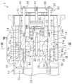
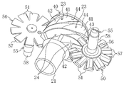
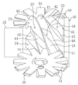
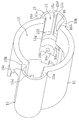
- FIG. 3 is a transverse sectional view taken along line III-III in FIG. 2. It is a perspective view which shows a screw rotor and a gate rotor. It is the perspective view which looked at the screw rotor and the gate rotor from another angle. It is a perspective view of a slide valve. It is a perspective view of a part of cylindrical wall of a casing.
- FIG. 2 is a sectional view taken along line VIII-VIII. It is a perspective view of the slide valve accommodated in the slide valve accommodation chamber. It is a longitudinal cross-sectional view corresponding to FIG. 2 of the single screw compressor in a state where the bypass port is open.
- FIG. 10 is a perspective view corresponding to FIG. 9 of the slide valve housed in the slide valve housing chamber in a state where the bypass port is open. It is a top view which shows operation
- Embodiment 1 of the Invention The screw compressor (1) which concerns on Embodiment 1 of this invention is provided in the refrigerant circuit which performs a refrigerating cycle, and is for compressing a refrigerant
- the screw compressor (1) is configured as a semi-hermetic type.
- a compression mechanism (20) and an electric motor (not shown) for driving the compression mechanism (20) are accommodated in one casing (10).
- the compression mechanism (20) is connected to the electric motor via the drive shaft (21).
- a low-pressure gas refrigerant is introduced from the evaporator of the refrigerant circuit and the low-pressure space (S1) for guiding the low-pressure gas to the compression mechanism (20), and the compression mechanism (20)
- a high-pressure space (S2) into which the discharged high-pressure gas refrigerant flows is partitioned.
- the compression mechanism (20) includes one screw rotor (40) and a cylindrical wall (10) that forms a part of the casing (10) and that defines a screw rotor housing chamber (12) that houses the screw rotor (40). 11) and two gate rotors (50) meshing with the screw rotor (40).
- the drive shaft (21) is inserted through the screw rotor (40).
- the screw rotor (40) and the drive shaft (21) are connected by a key (22).
- the drive shaft (21) is arranged coaxially with the screw rotor (40).
- the tip of the drive shaft (21) is a bearing holder (60) located on the high pressure space (S2) side of the compression mechanism (20) (right side when the axial direction of the drive shaft (21) in FIG. 2 is the left-right direction). ) Is rotatably supported.
- the bearing holder (60) supports the drive shaft (21) via a ball bearing (61).
- the screw rotor (40) is a metal member formed in a substantially cylindrical shape.
- the screw rotor (40) is rotatably fitted to the cylindrical wall (11), and the outer peripheral surface thereof is in sliding contact with the inner peripheral surface of the cylindrical wall (11).
- a plurality of spiral grooves (41, 41,...) Extending spirally from one end to the other end of the screw rotor (40) are formed on the outer peripheral portion of the screw rotor (40).
- Each spiral groove (41) of the screw rotor (40) starts at one end side (left side in FIG. 5) in the axial direction of the screw rotor (40) and ends at the other end side (right side in FIG. 5). Yes.
- the screw rotor (40) has a tapered peripheral surface at one end surface in the axial direction.
- the starting end of the spiral groove (41) opens to the tapered surface, while the end of the spiral groove (41) opens to the outer peripheral surface of the screw rotor (40) and does not open to the other end surface in the axial direction.
- the spiral groove (41) has a first side wall surface (42) positioned on the front side in the moving direction of the gate (51) described later of the gate rotor (50) and a rear side in the moving direction of the gate (51). It consists of two side wall surfaces (43) and a bottom wall surface (44).
- Each gate rotor (50) is a resin member provided with a plurality of gates (51) formed in a rectangular plate shape radially. Each gate rotor (50) is accommodated in a gate rotor accommodating chamber (13) which is arranged outside the cylindrical wall (11) and symmetrical about the rotational axis of the screw rotor (40) (see FIG. 3). reference).
- the gate rotor storage chamber (13) and the screw rotor storage chamber (12) communicate with each other through a slit (not shown) formed in the cylindrical wall (11).
- Each gate rotor (50) 51, 51,... Are arranged so as to penetrate the slits of the cylindrical wall (11) and engage with the spiral grooves (41, 41,...) Of the screw rotor (40).
- the gate rotor (50) is attached to a metal rotor support member (55) (see FIG. 4).
- the rotor support member (55) includes a base portion (56), an arm portion (57), and a shaft portion (58).
- the base (56) is formed in a slightly thick disk shape.
- the same number of arms (57) as the gates (51) of the gate rotor (50) are provided and extend radially outward from the outer peripheral surface of the base (56).
- the shaft portion (58) is formed in a rod shape and is erected on the base portion (56).
- the central axis of the shaft portion (58) coincides with the central axis of the base portion (56).
- the gate rotor (50) is attached to a surface of the base portion (56) and the arm portion (57) opposite to the shaft portion (58). Each arm portion (57) is in contact with the back surface (also referred to as the back surface) of the gate (51).
- the two gate rotors (50, 50) are arranged in the gate rotor accommodating chamber (13) so that the axis thereof is orthogonal to the plane including the axis of the screw rotor (40).
- each gate rotor (50) is arranged so that the surface thereof faces the rotational direction of the screw rotor (40) in a state where the gate rotor (50) meshes with the spiral groove (41) of the screw rotor (40). That is, each gate rotor (50) is arrange
- the two shaft portions (58, 58) extend in directions opposite to each other across a plane including the axis of the screw rotor (40). That is, in FIG. 3, the gate rotor (50) disposed on the left side is installed with the rotor support member (55) facing downward, while the gate rotor (50) disposed on the right side is supported by the rotor.
- the member (55) is installed in a posture facing upward.
- the shaft portion (58) of each rotor support member (55) is rotatably supported by a bearing housing (13a) in the gate rotor accommodating chamber (13) via ball bearings (13b, 13b).
- the closed space surrounded by the inner peripheral surface of the cylindrical wall (11), the spiral groove (41) of the screw rotor (40), and the gate (51) of the gate rotor (50) is compressed. It becomes room (23).
- the spiral groove (41) of the screw rotor (40) has a starting end opened to the low-pressure space (S1), and this open portion serves as a suction port (24) of the compression mechanism (20).
- the screw compressor (1) is provided with two slide valves (7) as a capacity control mechanism.
- the slide valve (7) constitutes a discharge port (73) and a bypass port (19a).
- the slide valve (7) has a cylindrical shape as a basic shape, a shape obtained by cutting a part of the cylindrical shape, and a valve body (71) provided on one side in the axial direction, It has a guide part (77) provided on the other side in the direction, and a port part (72) provided between the valve body (71) and the guide part (77).
- the valve body (71) is a boundary surface between the concave curved surface (71a) formed by cutting out a part of the outer peripheral surface of the cylinder in the axial direction and the port portion (72) and is inclined with respect to the axial direction.
- the inclined surface (71b), and the tip surface (71c) formed on a plane that is opposite to the inclined surface (71b) in the axial direction and orthogonal to the axial direction.
- the concave curved surface (71a) is recessed radially inward and has substantially the same curvature as the inner peripheral surface of the cylindrical wall (11), that is, substantially the same curvature as the outer peripheral surface of the screw rotor (40).
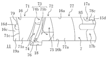
- the inclined surface (71b) is located at the end of the spiral groove (41) of the screw rotor (40) (screw rotor (40) (See FIG. 1 (A)).
- the valve body (71) configured in this way has a trapezoidal cross section cut along a plane parallel to the concave curved surface (71a). Further, the valve body (71) has a cross-sectional shape orthogonal to the axis, in which a part of a circle is cut out by a part of the outer periphery of another circle.
- the guide part (77) has a concave curved surface (77a) formed by cutting out a part of the outer peripheral surface of the cylinder in the axial direction, like the valve body (71).
- the concave curved surface (77a) is recessed radially inward and has substantially the same curvature as the inner peripheral surface of the cylindrical wall (11), that is, substantially the same curvature as that of the outer peripheral surface of the screw rotor (40). .
- the guide portion (77) is formed with two first and second notches (78a, 78b) on the opposite side of the concave curved surface (77a) (hereinafter also referred to as the back side) across the shaft. Yes.
- Each of the first and second cutout portions (78a, 78b) extends in the axial direction and is formed by cutting out into a substantially L-shaped cross section.
- the guide part (77) is formed with a back partition wall (78c) that is sandwiched between the two first and second cutout parts (78a, 78b) and protrudes to the back side.
- the first notch (78a), the second notch (78b), and the rear partition wall (78c) are also formed continuously in the port part (72), and the end on the valve body (71) side is inclined. It extends to the surface (71b).
- the guide part (77) has a substantially T-shaped cross section orthogonal to the axis.
- the protruding end surface of the partition wall (78c) is formed in the outer peripheral surface of a cylinder.
- the discharge port (73) is formed in the port part (72).
- the port portion (72) is adjacent to the concave curved surface (71a) of the valve body (71) in the axial direction, and has two first and second recesses that are recessed radially inward from the concave curved surface (71a).
- the port part (72) includes a first depression part (74), a partition wall (76), and a second depression part (75) in order from the valve body (71) side toward the other axial end side. It is formed side by side.
- the partition wall (76) is formed substantially parallel to the inclined surface (71b) of the valve body (71), and separates the first depression (74) and the second depression (75) in the axial direction. Yes.
- the front end surface of the partition wall (76) is recessed radially inward and has substantially the same curvature as the inner peripheral surface of the cylindrical wall (11), that is, substantially the same curvature as that of the outer peripheral surface of the screw rotor (40).
- the front end surface of the partition wall (76), the concave curved surface (71a) of the valve body (71) and the concave curved surface (77a) of the guide portion (77) form an inner peripheral surface of the same cylinder.
- the first depression (74) is formed between the inclined surface (71b) of the valve body (71) and the partition wall (76).
- the first depressed portion (74) has a depressed surface (74a) serving as a bottom surface.
- a first port (74b) is formed on the recessed surface (74a) toward the back surface side.
- the first port (74b) is formed in a groove shape by radially cutting a cylindrical portion between the first depression (74) and the first notch (78a). (74) and the 1st notch (78a) are connected.
- the second depression (75) is formed to be separated from the first depression (74) in the axial direction by the partition wall (76).
- the second depressed portion (75) has a depressed surface (75a) serving as a bottom surface.
- a second port (75b) is formed through the recessed surface (75a) toward the back side.
- the second port (75b) is formed in a groove shape by notching a cylindrical portion between the second depression (75) and the second notch (78b) in the radial direction. (75) and the 2nd notch (78b) are connected.
- the port part (72) has a substantially T-shaped cross section orthogonal to the axis, like the guide part (77). Further, in the port portion (72), a portion between the second depressed portion (75) and the first notched portion (78a), and a portion between the first depressed portion (74) and the second notched portion (78b). The part and the projecting end face of the back partition (78c) are formed in the shape of an outer peripheral surface of a cylinder.
- the slide valve (7) has a guide rod (79) extending in the axial direction from the valve body (71) and a connecting rod (85) extending in the axial direction from the guide portion (77).
- the slide valve (7) thus configured is accommodated in the slide valve accommodating chamber (14) formed in the cylindrical wall (11) of the casing (10) so as to be slidable in the axial direction.
- the slide valve storage chamber (14) is a symmetrical position on the cylindrical wall (11) across the axis of the screw rotor (40), and the spiral of the screw rotor (40). It is formed at a position corresponding to the end portion of the groove (41).
- the slide valve housing chamber (14) is a space extending in the axial direction of the screw rotor (40), and as shown in FIGS. 7 and 8, a fan-shaped peripheral wall (15) formed outside the cylindrical wall (11). And the cylindrical wall (11). In addition, in FIG. 7, parts other than the cylindrical wall (11) and the fan-shaped peripheral wall (15) in the casing (10) are not shown.
- the fan-shaped peripheral wall (15) has two side walls (15a, 15b) extending substantially radially outward from the cylindrical wall (11), and an arc wall (15c) connecting the tips of the two side walls (15a, 15b) in an arc shape. ) And has a substantially sectoral cross section.
- the arc wall (15c) is formed with an axial partition wall (15d) that protrudes radially inward at the circumferential central portion so as to extend in the axial direction. Furthermore, the arc wall (15c) has a circumferential partition wall (15) protruding radially inward at a position corresponding to the valve body (71) when the slide valve (7) is housed in the slide valve housing chamber (14). 15f) is formed extending in the circumferential direction. The circumferential partition (15f) extends from one side wall (15a) to the other side wall (15b) in the circumferential direction.
- the protruding end face (15g) of the circumferential partition wall (15f) has a cylindrical inner peripheral surface shape corresponding to the cylindrical outer peripheral surface of the valve body (71), and when the slide valve (7) is accommodated. It is in sliding contact with the cylindrical outer peripheral surface of the valve body (71).
- the axial partition (15d) extends to the circumferential partition (15f).
- the cylindrical wall (11) is formed with a slit-shaped opening (16) extending in the axial direction from the end surface on the high pressure space (S2) side to the low pressure space (S1) side.
- the opening (16) passes through the cylindrical wall (11) in the radial direction of the cylindrical wall (11), and allows the slide valve storage chamber (14) and the screw rotor storage chamber (12) to communicate with each other. .
- the two opening end faces (16a, 16b) facing in the circumferential direction slide together with the protruding end face (15e) of the axial partition wall (15d).
- An inner peripheral surface of a virtual cylinder extending in the axial direction in the valve accommodating chamber (14) is formed.
- This virtual cylinder is a cylinder corresponding to (that is, fitted to) the slide valve (7).
- the opening end surface (16c) on the axial low-pressure space (S1) side of the opening end surface of the cylindrical wall (11) is formed in a plane orthogonal to the axial direction, and the guide rod ( 79) is fitted with a guide hole (16d) in the axial direction.
- the slide valve (7) has an open end surface (16a, 16b) and a circular arc on the cylindrical wall (11), with the valve body (71) at the top, from the high-pressure space (S2) side into the slide valve storage chamber (14).
- the wall (15c) is inserted into a virtual cylinder formed by the protruding end surface (15e) of the axial partition wall (15d).
- the valve body (71) has a cylindrical outer peripheral surface in sliding contact with the open end faces (16a, 16b) of the cylindrical wall (11) and the protruding end face (15e) of the axial partition wall (15d). ing.
- the port portion (72) and the guide portion (77) have the first and second recessed portions (74, 75) and the cylindrical outer peripheral surface portion between the concave curved surface (77a) and the first notch portion (78a).
- the first and second depressions (74, 75) and the outer peripheral surface of the cylinder between the concave curved surface (77a) and the second notch (78b) are in the opening end surface (16b).
- the projecting end surface of the rear partition wall (78c) is in sliding contact with the projecting end surface (15e) of the axial partition wall (15d).
- the arc wall (15c), the side walls (15a, 15b), and the circumferential partition are formed on the back side of the slide valve (7).
- the discharge passage (17) is formed by sliding the axial partition (15d) of the fan-shaped peripheral wall (15) and the rear partition (78c) of the slide valve (7) into the first notch of the slide valve (7). It is divided into a first discharge passage (17a) in which the portion (78a) is located and a second discharge passage (17b) in which the second notch (78b) of the slide valve (7) is located.
- These first and second discharge passages (17a, 17b) open to the high-pressure space (S2).
- the concave curved surface (71a) of the slide valve (7) is exposed from the opening (16) into the screw rotor storage chamber (12).
- An inner peripheral surface of one cylinder is formed together with the inner peripheral surface of the cylindrical wall (11).
- the first and second depressions (74, 75) of the slide valve (7) are also exposed to the screw rotor accommodating chamber (12), and the first and second ports (74b, 75b) are accommodated in the screw rotor. Open to chamber (12).
- the screw rotor storage chamber (12) communicates with the first and second discharge passages (17a, 17b) via the first and second ports (74b, 75b).
- a fixed port (18) for discharging the gas refrigerant from the compression chamber (23) as much as possible is formed in the opening (16) of the cylindrical wall (11).
- the detailed operation of the fixed port (18) will be described later.
- a fixed port (18) is formed at the edge of the opening end surface (16b) of the cylindrical wall (11) on the screw rotor accommodating chamber (12) side.
- the fixed port (18) is formed on the open end surface (16b) of the cylindrical wall (11) and extends to the second discharge passage (17b). That is, the fixed port (18) always connects the screw rotor housing chamber (12) and the second discharge passage (17b) regardless of the position of the slide valve (7).
- the concave curved surface (77a) of the guide portion (77) is in sliding contact with the outer peripheral surface of the bearing holder (60) when the slide valve (7) is housed in the slide valve housing chamber (14).
- the concave curved surface (77a) of the guide portion (77) is in sliding contact with the outer peripheral surface of the bearing holder (60), so that the slide valve (7) is restricted from rotating around the axis, that is, around the axis. It is possible to slide in the axial direction while maintaining the posture. As a result, it is possible to prevent the valve body (71) and the port portion (72) from rotating around the axis due to gas pressure or the like and interfering with the tooth tip surface of the screw rotor (40).
- the opening end face (16c) on the axial low-pressure space (S1) side is the valve when the slide valve (7) is housed in the slide valve housing chamber (14). It is comprised so that it may closely_contact
- the tip end surface (71c) of the slide valve (7) is brought into intimate contact with the open end surface (16c) of the cylindrical wall (11)
- the opening (16) of the cylindrical wall (11) is closed by the slide valve (7). It becomes a state.
- the guide rod (79) of the slide valve (7) is slidably inserted into the guide hole (16d) of the open end face (16c).
- the slide valve (7) slides in the slide valve housing chamber (14) in the axial direction while being guided by the guide hole (16d) and the guide rod (79).
- a bypass passage (19) communicating with the opening (16) is formed outside the cylindrical wall (11) (see FIG. 2).
- the bypass passage (19) opens at the end of the opening (16) on the low pressure space (S1) side.
- the bypass passage (19) is separated from the first and second discharge passages (17a, 17b) by a circumferential partition (15f) that is in sliding contact with the cylindrical outer peripheral surface of the slide valve (7). That is, as shown in FIGS.
- the slide valve (7) is slid in the axial direction so that the tip surface (71c) of the slide valve (7) and the open end surface (16c) of the cylindrical wall (11)
- a bypass port (19a) communicating with the bypass passage (19) is formed at the end of the opening (16) on the low pressure space (S1) side.
- the bypass passage (19) communicates with the low pressure space (S1) and serves as a passage for returning the refrigerant from the compression chamber (23) to the low pressure space (S1).
- the screw compressor (1) is provided with a slide valve drive mechanism (80) for sliding the slide valve (7).
- the slide valve drive mechanism (80) includes a cylinder (81) fixed to the bearing holder (60), a piston (82) loaded in the cylinder (81), and a piston rod ( 83), a connecting rod (85, 85) for connecting the arm (84) and the slide valve (7), and a direction in which the arm (84) is separated from the compression mechanism (20) ( And a spring (86) biased in the right direction in FIG.
- the slide valve drive mechanism (80) in FIG. 2, the internal pressure of the left space of the piston (82) (the space on the screw rotor (40) side of the piston (82)) is changed to the right space (piston (82) of the piston (82). ) Is higher than the internal pressure of the arm (84) side.
- the slide valve drive mechanism (80) is configured to adjust the position of the slide valve (7) by adjusting the internal pressure in the right space of the piston (82) (ie, the gas pressure in the right space). ing.
- the screw rotor (40) rotates as the drive shaft (21) rotates.
- the gate rotor (50) also rotates, and the compression mechanism (20) repeats the suction stroke, the compression stroke, and the discharge stroke.
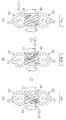
- the description will be given focusing on the spiral groove (41) shaded in FIG. 12, that is, the compression chamber (23).
- the compression chamber (23) with shading communicates with the low-pressure space (S1).
- the spiral groove (41) in which the compression chamber (23) is formed meshes with the gate (51) of the gate rotor (50) located on the lower side of the figure.
- the gate (51) relatively moves toward the terminal end of the spiral groove (41), and the volume of the compression chamber (23) increases accordingly.
- the low-pressure gas refrigerant in the low-pressure space (S1) is sucked into the compression chamber (23) through the suction port (24).
- the compression chamber (23) with shading is completely closed. That is, the spiral groove (41) in which the compression chamber (23) is formed meshes with the gate (51) of the gate rotor (50) located on the upper side of the figure, and the low pressure space ( It is partitioned from S1).
- the gate (51) moves toward the end of the spiral groove (41) as the screw rotor (40) rotates, the volume of the compression chamber (23) gradually decreases. As a result, the gas refrigerant in the compression chamber (23) is compressed.
- the gate (51) After the gate (51) reaches the position where the compression chamber (23) in the spiral groove (41) is completely closed, the side walls (42, 43) of the gate (51) and the spiral groove (41) And the bottom wall surface (44) need not physically rub against each other, and there may be a minute gap between them. That is, even if there are minute gaps between the gate (51) and the side wall surfaces (42, 43) and the bottom wall surface (44) of the spiral groove (41), the gap can be sealed with an oil film made of lubricating oil. If it is a thing, the airtightness of a compression chamber (23) is maintained, and the quantity of the gas refrigerant
- FIG. 1 (B) shows a state opening to the first and second depressions (74, 75) (that is, a state communicating with the first and second discharge passages (17a, 17b)), and FIG. 1 (C).
- the state changes to a state where only the second depressed portion (75) shown (ie, a state communicating with the second discharge passage (17b)) is opened. Thereafter, the spiral groove (41) does not open to the second depression (75).
- the fixed port (18) Open to. That is, by providing the fixed port (18), it is possible to delay the spiral groove (41) from being completely opened as much as possible and to discharge the gas refrigerant from the spiral groove (41) as much as possible. Yes.
- the screw rotor (40) immediately after the spiral groove (41) opens to the first depression (74), that is, immediately after the spiral groove (41b) opens to the first port (74b).
- the spiral groove (41) adjacent to the front side in the rotation direction (traveling side) has not yet detached from the second port (75b) and is open to the second port (75b).
- the spiral groove (41) (41) that has been opened earlier has almost completely discharged the refrigerant gas, and the pressure has dropped to the discharge port (73) compared to immediately after opening.
- the spiral groove immediately after the opening (hereinafter also referred to as the later spiral groove) (41) is in a state where the refrigerant gas is most compressed and in a high pressure state.
- the discharge port (73) is divided into the first port (74b) and the second port (75b) by the partition wall (76).
- the front end surface of the partition wall (76) and the inner peripheral surface of the cylindrical wall (11) form a cylindrical inner peripheral surface with which the tooth tips of the screw rotor (40) are in sliding contact with each other.
- the two ports (75b) open independently from the screw rotor storage chamber (12).
- the partition wall (76) is such that when the two adjacent spiral grooves (41, 41) are simultaneously open to the discharge port (73), the subsequent spiral groove (41) is open only to the first port (74b).
- the spiral groove (41) is provided at a position that opens only to the second port (75b).
- the previous spiral groove (41) opens only to the second port (75b) and does not open to the first port (74b).
- the rear spiral groove (41) opens only to the first port (74b) and does not open to the second port (74b). Therefore, the gas refrigerant discharged from the rear spiral groove (41) to the first port (74b) flows through the first discharge passage (17a) and flows out to the high-pressure space (S2).
- the gas refrigerant discharged from the spiral groove (41) to the second port (75b) flows through the second discharge passage (17b) and flows out into the high-pressure space (S2).
- the discharge port (73) is divided into the first port (74b) and the second port (75b) by the partition wall (76), the high pressure of the later spiral groove (41) Can be prevented from propagating to the spiral groove (41) and increasing the discharge work of the screw compressor (1).
- the slide valve (7) has a first port (74b), a second port (75b), and a partition wall depending on the position. Since the position of (76) also changes (see FIG. 10), it is possible to reliably prevent the preceding spiral groove (41) and the subsequent spiral groove (41) from opening simultaneously in the same discharge port (73). it can.
- the slide valve (7) closed the bypass port (19a) (that is, the tip surface (71c) of the valve body (71) is in close contact with the opening end surface (16c) of the opening (16)).
- a part of the refrigerant can be bypassed to the low-pressure space (S1) by moving the slide valve (7) to the high-pressure space (S2) in the axial direction.
- the first and second ports (74b, 75b) move in parallel in the axial direction as shown in FIG.
- the timing at which the spiral groove (41) opens to the discharge port (73), specifically, the first port (74b) simply changes.
- the timing at which the spiral groove (41) is detached from the discharge port (73) does not change even if the slide valve (7) moves. That is, the spiral groove (41) finally opens at the fixed port (18) and moves away from it.
- the end of the partition wall (76) on the front side in the rotational direction of the screw rotor (40) is located in the fixed port (18), and the first port (74b) and the second port (75b) are connected to the fixed port ( 18) may communicate via
- the opening timing of the spiral groove (41) to the discharge port (73) is delayed, when the subsequent spiral groove (41) opens to the first port (74b), the preceding spiral groove (41) gets closer to the state of being detached from the discharge port (73), and the opening area of the spiral groove (41) to the second port (75b) is smaller than that under high load.
- the opening area of the fixed port (18) to the first depression (74) and the second depression (75) is very small. Therefore, the influence of the communication between the first port (74b) and the second port (75b) via the fixed port (18) is small. Even in such a case, the partition wall (76) is provided, By dividing the first port (74b) and the second port (75b), it is possible to suppress the propagation of pressure from the subsequent spiral groove (41) to the preceding spiral groove (41). If you want to suppress the propagation of pressure through the fixed port (18), the bulkhead (76) is fixed even when the slide valve (7) is moved most to the high-pressure space (S2). What is necessary is just to set the shape of a partition (76) and the shape of a notch part (18a) so that it may not be located in a port (18) (it does not reach
- Embodiment 2 of the Invention ⁇ Embodiment 2 of the Invention >> Next, a slide valve according to Embodiment 2 of the present invention will be described.
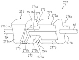
- the slide valve (207) according to the second embodiment is different from the first embodiment in the configuration of the port portion.
- Other configurations of the screw compressor are the same as those in the first embodiment. Therefore, the same configurations as those of the first embodiment are denoted by the same reference numerals, and the description thereof is omitted, and different configurations are mainly described.
- the partition wall (276) is formed in a substantially L shape at the port portion (272).
- the partition wall (276) is inclined from the front side (traveling side, lower side in FIG. 12) of the screw rotor (40) toward the rear side (front side, upper side in FIG. 12).
- the slide valve (207) is bent in the axial direction and extends in the axial direction.
- the port portion (272) is formed with a first depressed portion (274) and a second depressed portion (275) that are depressed radially inward from the concave curved surface (271a) of the valve body (271). .
- the first depressed portion (274) extends from between the inclined surface (271b) of the valve body (271) and the partition wall (276) to the region of the partition wall (276) on the rear side in the rotational direction of the screw rotor (40). Is formed.
- a first port (274b) is formed on the recessed surface (274a) of the first recessed portion (274), as in the first embodiment.
- the first port (274b) is formed in a groove shape by radially cutting a cylindrical side surface portion between the first depression (274) and the first notch (278a) on the back side.
- the first depression (274) and the first notch (278a) are communicated with each other.
- the second depression (275) is formed in a region of the partition wall (276) on the front side in the rotational direction of the screw rotor (40).
- a second port (275b) is formed on the depressed surface (275a) of the second depressed portion (275), as in the first embodiment.
- the second port (275b) is formed in a groove shape by radially notching a cylindrical side surface portion between the second depression (275) and the second notch (278b) on the back side.
- the second depression (275) and the second notch (278b) are in communication.
- first depression (274) and the second depression (275) are isolated by the partition wall (276). That is, the discharge port (273) is separated from the first port (274b) and the second port (275b) by the partition wall (276).
- the partition wall (276), the recessed surface (274a) of the first recessed portion (274), and the recessed surface (275a) of the second recessed portion (275) extend to the guide portion (277).
- the guide portion (277) extends in the axial direction of the screw rotor (40) at the rear edge in the rotational direction of the screw rotor (40) of the recessed surface (274a) of the first recessed portion (274) and The first guide portion (277a) protruding from the recessed surface (274a) and the screw rotor (40) at the front edge in the rotational direction of the screw rotor (40) of the recessed surface (275a) of the second recessed portion (275) A second guide portion (277b) extending in the axial direction and protruding from the recessed surface (275a) is formed.
- the protruding end surfaces of the first guide portion (277a) and the second guide portion (277b) and the protruding end surface of the partition wall (276) are curved in the same manner as the concave curved surface (271a) of the valve body (271).
- the inner peripheral surface of the same cylinder is formed together with the concave curved surface (271a). That is, the portion of the partition wall (276) positioned at the port portion (272) is in sliding contact with the outer peripheral surface of the screw rotor (40) together with the concave curved surface (271a) of the valve body (271).
- the part located in the guide part (277) of the partition wall (276) and the first guide part (277a) and the second guide part (277b) are configured to be in sliding contact with the outer peripheral surface of the bearing holder (60). Has been.
- the slide valve (207) configured in this manner is housed in the slide valve housing chamber (14) as in the first embodiment, and constitutes the discharge port (73) of the compression mechanism (20).
- the refrigerant gas discharged from the compression chamber (23) is discharged from the first and second discharge passages (17a, 17b) via the first and second ports (274b, 275b).
- a part of the refrigerant gas is formed by the first guide part (277a), the partition wall (276), and the bearing holder (60), and a second guide part. (277b), the partition wall (276), and the bearing holder (60) pass through the passage formed and flow out into the high-pressure space (S2).
- slide valve (207) according to the second embodiment can provide the same operations and effects as the first embodiment.
- the present invention is useful for a screw compressor in which two adjacent spiral grooves may open simultaneously to the discharge port.
Landscapes
- Engineering & Computer Science (AREA)
- Mechanical Engineering (AREA)
- General Engineering & Computer Science (AREA)
- Applications Or Details Of Rotary Compressors (AREA)
Abstract
L'invention porte sur un compresseur à vis fonctionnant avec un rendement de compression qui ne diminue pas lorsque deux rainures hélicoïdales adjacentes s'ouvrent simultanément sur un orifice de décharge. Le compresseur à vis (1) comporte un rotor à vis (40), un carter (10) pour recevoir le rotor à vis (40) et ayant l'orifice de décharge formé dans la surface périphérique interne du carter, et des rotors à ailettes (50) ayant des ailettes (51, 51, …) s'accouplant avec des rainures hélicoïdales (41) du rotor à vis (40). Une chambre de compression (23) formée par le rotor à vis (40), le carter (10) et les rotors à ailettes (50) comprime du gaz et décharge le gaz comprimé à partir de l'orifice de décharge. L'orifice de décharge est divisé en un premier orifice (74b) et un second orifice (75b) qui sont conçus de telle sorte que, lorsque deux rainures hélicoïdales adjacentes (41, 41) des rainures hélicoïdales (41) s'ouvrent sur l'orifice de décharge à mesure que le rotor à vis (40) tourne, l'une des deux rainures hélicoïdales adjacentes (41, 41) s'ouvre sur le premier orifice (74b) et l'autre s'ouvre sur le second orifice (75b).
Priority Applications (3)
| Application Number | Priority Date | Filing Date | Title |
|---|---|---|---|
| US12/810,951 US8845311B2 (en) | 2007-12-28 | 2008-12-26 | Screw compressor with adjacent helical grooves selectively opening to first and second ports |
| CN200880123392.3A CN101910641B (zh) | 2007-12-28 | 2008-12-26 | 螺杆压缩机 |
| EP08868532.6A EP2246572B1 (fr) | 2007-12-28 | 2008-12-26 | Compresseur à vis |
Applications Claiming Priority (2)
| Application Number | Priority Date | Filing Date | Title |
|---|---|---|---|
| JP2007-340274 | 2007-12-28 | ||
| JP2007340274 | 2007-12-28 |
Publications (1)
| Publication Number | Publication Date |
|---|---|
| WO2009084233A1 true WO2009084233A1 (fr) | 2009-07-09 |
Family
ID=40823969
Family Applications (1)
| Application Number | Title | Priority Date | Filing Date |
|---|---|---|---|
| PCT/JP2008/004026 WO2009084233A1 (fr) | 2007-12-28 | 2008-12-26 | Compresseur à vis |
Country Status (5)
| Country | Link |
|---|---|
| US (1) | US8845311B2 (fr) |
| EP (1) | EP2246572B1 (fr) |
| JP (1) | JP4301345B1 (fr) |
| CN (1) | CN101910641B (fr) |
| WO (1) | WO2009084233A1 (fr) |
Cited By (1)
| Publication number | Priority date | Publication date | Assignee | Title |
|---|---|---|---|---|
| JP2013127203A (ja) * | 2011-12-16 | 2013-06-27 | Mitsubishi Electric Corp | スクリュー圧縮機 |
Families Citing this family (10)
| Publication number | Priority date | Publication date | Assignee | Title |
|---|---|---|---|---|
| BRPI0808620A2 (pt) * | 2007-03-29 | 2014-08-12 | Vilter Mfg Llc | "compressor, conjunto de válvula de gaveta de alta pressão para uso em um compressor e método de controle de taxa de volume de compressão, de entrada de potência e de capacidade em um compressor operando em um ambiente de alta pressão" |
| GB0821275D0 (en) | 2008-11-20 | 2008-12-31 | Aaf Mcquay Inc | Screw compressor |
| BR112013006770A2 (pt) * | 2010-09-30 | 2020-12-15 | Daikin Industries Ltd. | Compressor de rosca |
| WO2013078132A1 (fr) * | 2011-11-22 | 2013-05-30 | Vilter Manufacturing Llc | Appareil de detente/compression monovis |
| US9057373B2 (en) | 2011-11-22 | 2015-06-16 | Vilter Manufacturing Llc | Single screw compressor with high output |
| CN102661279B (zh) * | 2012-05-23 | 2016-01-27 | 贵州中电振华精密机械有限公司 | 单螺杆压缩机 |
| JP2014047708A (ja) * | 2012-08-31 | 2014-03-17 | Mitsubishi Electric Corp | スクリュー圧縮機 |
| JP6058133B2 (ja) * | 2013-05-30 | 2017-01-11 | 三菱電機株式会社 | スクリュー圧縮機及び冷凍サイクル装置 |
| EP3842641B1 (fr) | 2018-08-23 | 2023-11-22 | Mitsubishi Electric Corporation | Compresseur à vis |
| WO2022244219A1 (fr) * | 2021-05-21 | 2022-11-24 | 三菱電機株式会社 | Compresseur à vis |
Citations (4)
| Publication number | Priority date | Publication date | Assignee | Title |
|---|---|---|---|---|
| JPH09291891A (ja) * | 1996-04-26 | 1997-11-11 | Hitachi Ltd | スクリュー圧縮機 |
| JP2005054719A (ja) * | 2003-08-06 | 2005-03-03 | Daikin Ind Ltd | スクリュー圧縮機 |
| JP2005090293A (ja) | 2003-09-16 | 2005-04-07 | Daikin Ind Ltd | シングルスクリュー圧縮機 |
| US20050123429A1 (en) * | 2003-12-09 | 2005-06-09 | Dresser-Rand Company | Compressor and a method for compressing fluid |
Family Cites Families (14)
| Publication number | Priority date | Publication date | Assignee | Title |
|---|---|---|---|---|
| US3088658A (en) * | 1959-06-04 | 1963-05-07 | Svenska Rotor Maskiner Ab | Angularly adjustable slides for screw rotor machines |
| US3088659A (en) * | 1960-06-17 | 1963-05-07 | Svenska Rotor Maskiner Ab | Means for regulating helical rotary piston engines |
| USRE29283E (en) * | 1974-07-26 | 1977-06-28 | Dunham-Bush, Inc. | Undercompression and overcompression free helical screw rotary compressor |
| GB1555329A (en) * | 1975-08-21 | 1979-11-07 | Hall Thermotank Prod Ltd | Rotary fluid machines |
| GB1555330A (en) * | 1978-03-21 | 1979-11-07 | Hall Thermotank Prod Ltd | Rotary fluid machines |
| USRE31379E (en) * | 1979-06-01 | 1983-09-13 | Dunham-Bush, Inc. | Combined pressure matching and capacity control slide valve assembly for helical screw rotary machine |
| US4388040A (en) * | 1979-12-14 | 1983-06-14 | Nippon Piston Ring Co., Ltd. | Rotary fluid pump |
| US4388048A (en) * | 1981-03-10 | 1983-06-14 | Dunham Bush, Inc. | Stepping type unloading system for helical screw rotary compressor |
| US4548549A (en) * | 1982-09-10 | 1985-10-22 | Frick Company | Micro-processor control of compression ratio at full load in a helical screw rotary compressor responsive to compressor drive motor current |
| US4609329A (en) * | 1985-04-05 | 1986-09-02 | Frick Company | Micro-processor control of a movable slide stop and a movable slide valve in a helical screw rotary compressor with an enconomizer inlet port |
| US4610612A (en) * | 1985-06-03 | 1986-09-09 | Vilter Manufacturing Corporation | Rotary screw gas compressor having dual slide valves |
| US4610613A (en) * | 1985-06-03 | 1986-09-09 | Vilter Manufacturing Corporation | Control means for gas compressor having dual slide valves |
| FR2733549A1 (fr) * | 1995-04-28 | 1996-10-31 | Zimmern Bernard | Compresseur a vis avec protection des coups de liquide |
| US7080977B2 (en) * | 2003-03-25 | 2006-07-25 | Carrier Corporation | Discharge diffuser for screw compressor |
-
2008
- 2008-12-26 EP EP08868532.6A patent/EP2246572B1/fr not_active Not-in-force
- 2008-12-26 JP JP2008332696A patent/JP4301345B1/ja not_active Expired - Fee Related
- 2008-12-26 CN CN200880123392.3A patent/CN101910641B/zh not_active Expired - Fee Related
- 2008-12-26 WO PCT/JP2008/004026 patent/WO2009084233A1/fr active Application Filing
- 2008-12-26 US US12/810,951 patent/US8845311B2/en not_active Expired - Fee Related
Patent Citations (4)
| Publication number | Priority date | Publication date | Assignee | Title |
|---|---|---|---|---|
| JPH09291891A (ja) * | 1996-04-26 | 1997-11-11 | Hitachi Ltd | スクリュー圧縮機 |
| JP2005054719A (ja) * | 2003-08-06 | 2005-03-03 | Daikin Ind Ltd | スクリュー圧縮機 |
| JP2005090293A (ja) | 2003-09-16 | 2005-04-07 | Daikin Ind Ltd | シングルスクリュー圧縮機 |
| US20050123429A1 (en) * | 2003-12-09 | 2005-06-09 | Dresser-Rand Company | Compressor and a method for compressing fluid |
Non-Patent Citations (1)
| Title |
|---|
| See also references of EP2246572A4 * |
Cited By (1)
| Publication number | Priority date | Publication date | Assignee | Title |
|---|---|---|---|---|
| JP2013127203A (ja) * | 2011-12-16 | 2013-06-27 | Mitsubishi Electric Corp | スクリュー圧縮機 |
Also Published As
| Publication number | Publication date |
|---|---|
| EP2246572A1 (fr) | 2010-11-03 |
| US8845311B2 (en) | 2014-09-30 |
| EP2246572B1 (fr) | 2015-09-23 |
| JP4301345B1 (ja) | 2009-07-22 |
| EP2246572A4 (fr) | 2014-12-17 |
| CN101910641A (zh) | 2010-12-08 |
| JP2009174527A (ja) | 2009-08-06 |
| CN101910641B (zh) | 2013-04-10 |
| US20100284848A1 (en) | 2010-11-11 |
Similar Documents
| Publication | Publication Date | Title |
|---|---|---|
| JP4301345B1 (ja) | スクリュー圧縮機 | |
| US8366405B2 (en) | Screw compressor with capacity control slide valve | |
| WO2012042891A1 (fr) | Compresseur à vis | |
| JP4645754B2 (ja) | スクリュー圧縮機 | |
| JP5494465B2 (ja) | スクロール圧縮機 | |
| JP5125524B2 (ja) | スクリュー圧縮機 | |
| CN210087602U (zh) | 涡旋式压缩机 | |
| JP2004324601A (ja) | シングルスクリュー圧縮機 | |
| JP2009167846A5 (fr) | ||
| JP5526760B2 (ja) | シングルスクリュー圧縮機 | |
| JP2022075840A (ja) | スクリュー圧縮機 | |
| JP4735757B2 (ja) | シングルスクリュー圧縮機 | |
| JP6500964B1 (ja) | スクリュー圧縮機 | |
| JP2012197734A (ja) | スクリュー圧縮機 | |
| JP2013068093A (ja) | スクリュー圧縮機 | |
| JP2018009516A (ja) | スクリュー圧縮機 | |
| JP6728988B2 (ja) | スクリュー圧縮機 | |
| US11493041B2 (en) | Scroll compressor | |
| JP2004316586A (ja) | スクリュー圧縮機 | |
| JP2006046094A (ja) | 容量可変型気体圧縮機 | |
| JP2006077597A (ja) | 気体圧縮機 | |
| JP2017201146A (ja) | スクリュー圧縮機 | |
| KR100750303B1 (ko) | 스크롤 압축기 | |
| JP2011163237A (ja) | スクロール圧縮機 | |
| JP2004052608A (ja) | 気体圧縮機 |
Legal Events
| Date | Code | Title | Description |
|---|---|---|---|
| WWE | Wipo information: entry into national phase |
Ref document number: 200880123392.3 Country of ref document: CN |
|
| 121 | Ep: the epo has been informed by wipo that ep was designated in this application |
Ref document number: 08868532 Country of ref document: EP Kind code of ref document: A1 |
|
| WWE | Wipo information: entry into national phase |
Ref document number: 12810951 Country of ref document: US |
|
| NENP | Non-entry into the national phase |
Ref country code: DE |
|
| WWE | Wipo information: entry into national phase |
Ref document number: 2008868532 Country of ref document: EP |