WO2009084233A1 - Screw compressor - Google Patents
Screw compressor Download PDFInfo
- Publication number
- WO2009084233A1 WO2009084233A1 PCT/JP2008/004026 JP2008004026W WO2009084233A1 WO 2009084233 A1 WO2009084233 A1 WO 2009084233A1 JP 2008004026 W JP2008004026 W JP 2008004026W WO 2009084233 A1 WO2009084233 A1 WO 2009084233A1
- Authority
- WO
- WIPO (PCT)
- Prior art keywords
- port
- spiral groove
- screw rotor
- slide valve
- discharge
- Prior art date
Links
Images


Classifications
-
- F—MECHANICAL ENGINEERING; LIGHTING; HEATING; WEAPONS; BLASTING
- F04—POSITIVE - DISPLACEMENT MACHINES FOR LIQUIDS; PUMPS FOR LIQUIDS OR ELASTIC FLUIDS
- F04C—ROTARY-PISTON, OR OSCILLATING-PISTON, POSITIVE-DISPLACEMENT MACHINES FOR LIQUIDS; ROTARY-PISTON, OR OSCILLATING-PISTON, POSITIVE-DISPLACEMENT PUMPS
- F04C18/00—Rotary-piston pumps specially adapted for elastic fluids
- F04C18/48—Rotary-piston pumps with non-parallel axes of movement of co-operating members
- F04C18/50—Rotary-piston pumps with non-parallel axes of movement of co-operating members the axes being arranged at an angle of 90 degrees
- F04C18/52—Rotary-piston pumps with non-parallel axes of movement of co-operating members the axes being arranged at an angle of 90 degrees of intermeshing engagement type, i.e. with engagement of co-operating members similar to that of toothed gearing
-
- F—MECHANICAL ENGINEERING; LIGHTING; HEATING; WEAPONS; BLASTING
- F01—MACHINES OR ENGINES IN GENERAL; ENGINE PLANTS IN GENERAL; STEAM ENGINES
- F01C—ROTARY-PISTON OR OSCILLATING-PISTON MACHINES OR ENGINES
- F01C17/00—Arrangements for drive of co-operating members, e.g. for rotary piston and casing
- F01C17/02—Arrangements for drive of co-operating members, e.g. for rotary piston and casing of toothed-gearing type
-
- F—MECHANICAL ENGINEERING; LIGHTING; HEATING; WEAPONS; BLASTING
- F04—POSITIVE - DISPLACEMENT MACHINES FOR LIQUIDS; PUMPS FOR LIQUIDS OR ELASTIC FLUIDS
- F04C—ROTARY-PISTON, OR OSCILLATING-PISTON, POSITIVE-DISPLACEMENT MACHINES FOR LIQUIDS; ROTARY-PISTON, OR OSCILLATING-PISTON, POSITIVE-DISPLACEMENT PUMPS
- F04C23/00—Combinations of two or more pumps, each being of rotary-piston or oscillating-piston type, specially adapted for elastic fluids; Pumping installations specially adapted for elastic fluids; Multi-stage pumps specially adapted for elastic fluids
- F04C23/001—Combinations of two or more pumps, each being of rotary-piston or oscillating-piston type, specially adapted for elastic fluids; Pumping installations specially adapted for elastic fluids; Multi-stage pumps specially adapted for elastic fluids of similar working principle
-
- F—MECHANICAL ENGINEERING; LIGHTING; HEATING; WEAPONS; BLASTING
- F04—POSITIVE - DISPLACEMENT MACHINES FOR LIQUIDS; PUMPS FOR LIQUIDS OR ELASTIC FLUIDS
- F04C—ROTARY-PISTON, OR OSCILLATING-PISTON, POSITIVE-DISPLACEMENT MACHINES FOR LIQUIDS; ROTARY-PISTON, OR OSCILLATING-PISTON, POSITIVE-DISPLACEMENT PUMPS
- F04C27/00—Sealing arrangements in rotary-piston pumps specially adapted for elastic fluids
- F04C27/001—Radial sealings for working fluid
- F04C27/004—Radial sealing elements specially adapted for intermeshing-engagement type pumps, e.g. gear pumps
-
- F—MECHANICAL ENGINEERING; LIGHTING; HEATING; WEAPONS; BLASTING
- F04—POSITIVE - DISPLACEMENT MACHINES FOR LIQUIDS; PUMPS FOR LIQUIDS OR ELASTIC FLUIDS
- F04C—ROTARY-PISTON, OR OSCILLATING-PISTON, POSITIVE-DISPLACEMENT MACHINES FOR LIQUIDS; ROTARY-PISTON, OR OSCILLATING-PISTON, POSITIVE-DISPLACEMENT PUMPS
- F04C29/00—Component parts, details or accessories of pumps or pumping installations, not provided for in groups F04C18/00 - F04C28/00
- F04C29/0042—Driving elements, brakes, couplings, transmissions specially adapted for pumps
- F04C29/0078—Fixing rotors on shafts, e.g. by clamping together hub and shaft
-
- F—MECHANICAL ENGINEERING; LIGHTING; HEATING; WEAPONS; BLASTING
- F04—POSITIVE - DISPLACEMENT MACHINES FOR LIQUIDS; PUMPS FOR LIQUIDS OR ELASTIC FLUIDS
- F04C—ROTARY-PISTON, OR OSCILLATING-PISTON, POSITIVE-DISPLACEMENT MACHINES FOR LIQUIDS; ROTARY-PISTON, OR OSCILLATING-PISTON, POSITIVE-DISPLACEMENT PUMPS
- F04C29/00—Component parts, details or accessories of pumps or pumping installations, not provided for in groups F04C18/00 - F04C28/00
- F04C29/12—Arrangements for admission or discharge of the working fluid, e.g. constructional features of the inlet or outlet
- F04C29/124—Arrangements for admission or discharge of the working fluid, e.g. constructional features of the inlet or outlet with inlet and outlet valves specially adapted for rotary or oscillating piston pumps
-
- F—MECHANICAL ENGINEERING; LIGHTING; HEATING; WEAPONS; BLASTING
- F04—POSITIVE - DISPLACEMENT MACHINES FOR LIQUIDS; PUMPS FOR LIQUIDS OR ELASTIC FLUIDS
- F04C—ROTARY-PISTON, OR OSCILLATING-PISTON, POSITIVE-DISPLACEMENT MACHINES FOR LIQUIDS; ROTARY-PISTON, OR OSCILLATING-PISTON, POSITIVE-DISPLACEMENT PUMPS
- F04C18/00—Rotary-piston pumps specially adapted for elastic fluids
- F04C18/08—Rotary-piston pumps specially adapted for elastic fluids of intermeshing-engagement type, i.e. with engagement of co-operating members similar to that of toothed gearing
- F04C18/12—Rotary-piston pumps specially adapted for elastic fluids of intermeshing-engagement type, i.e. with engagement of co-operating members similar to that of toothed gearing of other than internal-axis type
- F04C18/14—Rotary-piston pumps specially adapted for elastic fluids of intermeshing-engagement type, i.e. with engagement of co-operating members similar to that of toothed gearing of other than internal-axis type with toothed rotary pistons
- F04C18/16—Rotary-piston pumps specially adapted for elastic fluids of intermeshing-engagement type, i.e. with engagement of co-operating members similar to that of toothed gearing of other than internal-axis type with toothed rotary pistons with helical teeth, e.g. chevron-shaped, screw type
-
- F—MECHANICAL ENGINEERING; LIGHTING; HEATING; WEAPONS; BLASTING
- F04—POSITIVE - DISPLACEMENT MACHINES FOR LIQUIDS; PUMPS FOR LIQUIDS OR ELASTIC FLUIDS
- F04C—ROTARY-PISTON, OR OSCILLATING-PISTON, POSITIVE-DISPLACEMENT MACHINES FOR LIQUIDS; ROTARY-PISTON, OR OSCILLATING-PISTON, POSITIVE-DISPLACEMENT PUMPS
- F04C2240/00—Components
- F04C2240/30—Casings or housings
-
- F—MECHANICAL ENGINEERING; LIGHTING; HEATING; WEAPONS; BLASTING
- F04—POSITIVE - DISPLACEMENT MACHINES FOR LIQUIDS; PUMPS FOR LIQUIDS OR ELASTIC FLUIDS
- F04C—ROTARY-PISTON, OR OSCILLATING-PISTON, POSITIVE-DISPLACEMENT MACHINES FOR LIQUIDS; ROTARY-PISTON, OR OSCILLATING-PISTON, POSITIVE-DISPLACEMENT PUMPS
- F04C2240/00—Components
- F04C2240/50—Bearings
- F04C2240/52—Bearings for assemblies with supports on both sides
-
- F—MECHANICAL ENGINEERING; LIGHTING; HEATING; WEAPONS; BLASTING
- F04—POSITIVE - DISPLACEMENT MACHINES FOR LIQUIDS; PUMPS FOR LIQUIDS OR ELASTIC FLUIDS
- F04C—ROTARY-PISTON, OR OSCILLATING-PISTON, POSITIVE-DISPLACEMENT MACHINES FOR LIQUIDS; ROTARY-PISTON, OR OSCILLATING-PISTON, POSITIVE-DISPLACEMENT PUMPS
- F04C2240/00—Components
- F04C2240/60—Shafts
- F04C2240/603—Shafts with internal channels for fluid distribution, e.g. hollow shaft
-
- F—MECHANICAL ENGINEERING; LIGHTING; HEATING; WEAPONS; BLASTING
- F04—POSITIVE - DISPLACEMENT MACHINES FOR LIQUIDS; PUMPS FOR LIQUIDS OR ELASTIC FLUIDS
- F04C—ROTARY-PISTON, OR OSCILLATING-PISTON, POSITIVE-DISPLACEMENT MACHINES FOR LIQUIDS; ROTARY-PISTON, OR OSCILLATING-PISTON, POSITIVE-DISPLACEMENT PUMPS
- F04C2270/00—Control; Monitoring or safety arrangements
- F04C2270/16—Wear
-
- F—MECHANICAL ENGINEERING; LIGHTING; HEATING; WEAPONS; BLASTING
- F04—POSITIVE - DISPLACEMENT MACHINES FOR LIQUIDS; PUMPS FOR LIQUIDS OR ELASTIC FLUIDS
- F04C—ROTARY-PISTON, OR OSCILLATING-PISTON, POSITIVE-DISPLACEMENT MACHINES FOR LIQUIDS; ROTARY-PISTON, OR OSCILLATING-PISTON, POSITIVE-DISPLACEMENT PUMPS
- F04C2270/00—Control; Monitoring or safety arrangements
- F04C2270/17—Tolerance; Play; Gap
-
- F—MECHANICAL ENGINEERING; LIGHTING; HEATING; WEAPONS; BLASTING
- F04—POSITIVE - DISPLACEMENT MACHINES FOR LIQUIDS; PUMPS FOR LIQUIDS OR ELASTIC FLUIDS
- F04C—ROTARY-PISTON, OR OSCILLATING-PISTON, POSITIVE-DISPLACEMENT MACHINES FOR LIQUIDS; ROTARY-PISTON, OR OSCILLATING-PISTON, POSITIVE-DISPLACEMENT PUMPS
- F04C2270/00—Control; Monitoring or safety arrangements
- F04C2270/58—Valve parameters
-
- F—MECHANICAL ENGINEERING; LIGHTING; HEATING; WEAPONS; BLASTING
- F04—POSITIVE - DISPLACEMENT MACHINES FOR LIQUIDS; PUMPS FOR LIQUIDS OR ELASTIC FLUIDS
- F04C—ROTARY-PISTON, OR OSCILLATING-PISTON, POSITIVE-DISPLACEMENT MACHINES FOR LIQUIDS; ROTARY-PISTON, OR OSCILLATING-PISTON, POSITIVE-DISPLACEMENT PUMPS
- F04C27/00—Sealing arrangements in rotary-piston pumps specially adapted for elastic fluids
- F04C27/007—Sealings for working fluid between radially and axially moving parts
Definitions
- the present invention relates to a screw compressor.
- a compressor for compressing a gas such as refrigerant or air
- a single screw compressor including one screw rotor, a casing for housing the screw rotor, and two gate rotors is known (Patent Document 1). reference).
- This screw compressor forms a compression chamber by a closed space defined by a spiral groove of a screw rotor, a casing, and a gate of a gate rotor.
- the gate By rotating the screw rotor, the gate relatively moves in the spiral groove of the screw rotor and compresses the gas in the compression chamber.
- the casing is provided with a discharge port at a position corresponding to the vicinity of the end of the spiral groove of the screw rotor, and the helical groove opens to the discharge port as the screw rotor rotates, thereby compressing the high-pressure gas. Is discharged from the discharge port. JP 2005-90293 A
- two adjacent spiral grooves may open to the discharge port at the same time. That is, the next spiral groove may open to the discharge port immediately before the spiral groove previously opened to the discharge port is removed from the discharge port (no longer opened to the discharge port).
- the first spiral groove is almost completely discharged and its internal pressure is lower than that immediately after discharge, whereas the latter spiral groove is immediately after the start of discharge and its internal pressure is high. Yes. For this reason, the pressure immediately after the discharge of the subsequent spiral groove propagates to the previous spiral groove, which may increase the discharge work and reduce the compressor efficiency.
- the present invention has been made in view of such a point, and an object of the present invention is to prevent a reduction in compressor efficiency due to two adjacent spiral grooves opening simultaneously into the discharge port.
- the first invention includes a screw rotor (40) in which a plurality of spiral grooves (41, 41,...) Are formed, and a casing that houses the screw rotor (40) and is provided with a discharge port on the inner peripheral surface thereof. (10) and a gate rotor (50) having a gate (51, 51,%) Meshing with the spiral groove (41, 41,...) Of the screw rotor (40). , ...), the casing (10), and the gate (51,51, ...) are compressed in a compression chamber (23,23, ...) and discharged from the discharge port (73,73).
- the target is screw compressors.
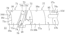
- the discharge port (73) has two adjacent spiral grooves (41, 41) of the spiral grooves (41, 41,7) Opened to the discharge port as the screw rotor (40) rotates. It is assumed that the first port (74b) in which one of the spiral grooves (41) is opened and the second port (75b) in which the other spiral groove (41) is opened are divided.
- spiral groove (41) When only one spiral groove (41) opens in the discharge port (73), the spiral groove (41) straddles the first and second ports (74b, 75b) or the first and second ports. Only one of (74b, 75b) can be opened.
- the casing (10) is formed with an opening (16), and the slide disposed in the opening (16) of the casing (10).
- the slide valve (7) further includes a valve (7), and the first and second ports (74b, 75b) and a partition that divides the first port (74b) and the second port (75b) (76) shall be provided.
- the slide valve (7) constituting the discharge port (73) is provided with a partition wall (76) that divides the discharge port (73) into a first port (74b) and a second port (75b).
- the casing (10) has a discharge passage (17, 73) communicating with the discharge port (73, 73) on the downstream side of the discharge port (73, 73). 17) is formed, and the discharge passage (17) includes a first discharge passage (17a) communicating with the first port (74b) and a second discharge passage (communication with the second port (75b)). 17b).
- the first and second discharge passages (17a, 17b) communicating with the first and second ports (74b, 75b) on the downstream side of the first and second ports (74b, 75b), respectively.
- the gas does not immediately merge after flowing out from the first and second ports (74b, 75b) to the first and second discharge passages (17a, 17b), respectively. Propagation of the discharge pressure from the immediately following spiral groove (41) to the spiral groove (41) just before detaching from the discharge port (73) can be further reliably suppressed.
- the discharge port (73) is connected to the first port (one spiral groove (41) opened when two adjacent spiral grooves (41, 41) open to the discharge port (73)). 74b) and the second port (75b) in which the other spiral groove (41) is opened, the discharge pressure from the spiral groove (41) immediately after opening to the discharge port (73) Since propagation to the spiral groove (41) is suppressed, discharge work can be reduced and compressor efficiency can be improved.
- the discharge port (73) has the first and second ports (74b, 75b), and the partition wall (76) dividing the first port (74b) and the second port (75b) has a slide valve. Even if the timing at which the two adjacent spiral grooves (41, 41) are simultaneously opened to the discharge port (73) is changed by changing the position of the slide valve (7), Propagation of the discharge pressure from the spiral groove (41) immediately after opening to the port (73) to the spiral groove (41) immediately before coming out of the discharge port (73) can be suppressed.
- the discharge passage (17) communicating with the discharge port (73) communicates with the first discharge passage (17a) communicating with the first port (74b) and the second port (75b).
- the discharge pressure from the spiral groove (41) immediately after opening to the discharge port (73) is propagated to the spiral groove (41) just before coming out of the discharge port (73). It can be surely suppressed.
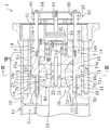
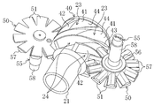
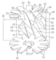
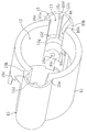
- FIG. 3 is a transverse sectional view taken along line III-III in FIG. 2. It is a perspective view which shows a screw rotor and a gate rotor. It is the perspective view which looked at the screw rotor and the gate rotor from another angle. It is a perspective view of a slide valve. It is a perspective view of a part of cylindrical wall of a casing.
- FIG. 2 is a sectional view taken along line VIII-VIII. It is a perspective view of the slide valve accommodated in the slide valve accommodation chamber. It is a longitudinal cross-sectional view corresponding to FIG. 2 of the single screw compressor in a state where the bypass port is open.
- FIG. 10 is a perspective view corresponding to FIG. 9 of the slide valve housed in the slide valve housing chamber in a state where the bypass port is open. It is a top view which shows operation
- Embodiment 1 of the Invention The screw compressor (1) which concerns on Embodiment 1 of this invention is provided in the refrigerant circuit which performs a refrigerating cycle, and is for compressing a refrigerant
- the screw compressor (1) is configured as a semi-hermetic type.
- a compression mechanism (20) and an electric motor (not shown) for driving the compression mechanism (20) are accommodated in one casing (10).
- the compression mechanism (20) is connected to the electric motor via the drive shaft (21).
- a low-pressure gas refrigerant is introduced from the evaporator of the refrigerant circuit and the low-pressure space (S1) for guiding the low-pressure gas to the compression mechanism (20), and the compression mechanism (20)
- a high-pressure space (S2) into which the discharged high-pressure gas refrigerant flows is partitioned.
- the compression mechanism (20) includes one screw rotor (40) and a cylindrical wall (10) that forms a part of the casing (10) and that defines a screw rotor housing chamber (12) that houses the screw rotor (40). 11) and two gate rotors (50) meshing with the screw rotor (40).
- the drive shaft (21) is inserted through the screw rotor (40).
- the screw rotor (40) and the drive shaft (21) are connected by a key (22).
- the drive shaft (21) is arranged coaxially with the screw rotor (40).
- the tip of the drive shaft (21) is a bearing holder (60) located on the high pressure space (S2) side of the compression mechanism (20) (right side when the axial direction of the drive shaft (21) in FIG. 2 is the left-right direction). ) Is rotatably supported.
- the bearing holder (60) supports the drive shaft (21) via a ball bearing (61).
- the screw rotor (40) is a metal member formed in a substantially cylindrical shape.
- the screw rotor (40) is rotatably fitted to the cylindrical wall (11), and the outer peripheral surface thereof is in sliding contact with the inner peripheral surface of the cylindrical wall (11).
- a plurality of spiral grooves (41, 41,...) Extending spirally from one end to the other end of the screw rotor (40) are formed on the outer peripheral portion of the screw rotor (40).
- Each spiral groove (41) of the screw rotor (40) starts at one end side (left side in FIG. 5) in the axial direction of the screw rotor (40) and ends at the other end side (right side in FIG. 5). Yes.
- the screw rotor (40) has a tapered peripheral surface at one end surface in the axial direction.
- the starting end of the spiral groove (41) opens to the tapered surface, while the end of the spiral groove (41) opens to the outer peripheral surface of the screw rotor (40) and does not open to the other end surface in the axial direction.
- the spiral groove (41) has a first side wall surface (42) positioned on the front side in the moving direction of the gate (51) described later of the gate rotor (50) and a rear side in the moving direction of the gate (51). It consists of two side wall surfaces (43) and a bottom wall surface (44).
- Each gate rotor (50) is a resin member provided with a plurality of gates (51) formed in a rectangular plate shape radially. Each gate rotor (50) is accommodated in a gate rotor accommodating chamber (13) which is arranged outside the cylindrical wall (11) and symmetrical about the rotational axis of the screw rotor (40) (see FIG. 3). reference).
- the gate rotor storage chamber (13) and the screw rotor storage chamber (12) communicate with each other through a slit (not shown) formed in the cylindrical wall (11).
- Each gate rotor (50) 51, 51,... Are arranged so as to penetrate the slits of the cylindrical wall (11) and engage with the spiral grooves (41, 41,...) Of the screw rotor (40).
- the gate rotor (50) is attached to a metal rotor support member (55) (see FIG. 4).
- the rotor support member (55) includes a base portion (56), an arm portion (57), and a shaft portion (58).
- the base (56) is formed in a slightly thick disk shape.
- the same number of arms (57) as the gates (51) of the gate rotor (50) are provided and extend radially outward from the outer peripheral surface of the base (56).
- the shaft portion (58) is formed in a rod shape and is erected on the base portion (56).
- the central axis of the shaft portion (58) coincides with the central axis of the base portion (56).
- the gate rotor (50) is attached to a surface of the base portion (56) and the arm portion (57) opposite to the shaft portion (58). Each arm portion (57) is in contact with the back surface (also referred to as the back surface) of the gate (51).
- the two gate rotors (50, 50) are arranged in the gate rotor accommodating chamber (13) so that the axis thereof is orthogonal to the plane including the axis of the screw rotor (40).
- each gate rotor (50) is arranged so that the surface thereof faces the rotational direction of the screw rotor (40) in a state where the gate rotor (50) meshes with the spiral groove (41) of the screw rotor (40). That is, each gate rotor (50) is arrange
- the two shaft portions (58, 58) extend in directions opposite to each other across a plane including the axis of the screw rotor (40). That is, in FIG. 3, the gate rotor (50) disposed on the left side is installed with the rotor support member (55) facing downward, while the gate rotor (50) disposed on the right side is supported by the rotor.
- the member (55) is installed in a posture facing upward.
- the shaft portion (58) of each rotor support member (55) is rotatably supported by a bearing housing (13a) in the gate rotor accommodating chamber (13) via ball bearings (13b, 13b).
- the closed space surrounded by the inner peripheral surface of the cylindrical wall (11), the spiral groove (41) of the screw rotor (40), and the gate (51) of the gate rotor (50) is compressed. It becomes room (23).
- the spiral groove (41) of the screw rotor (40) has a starting end opened to the low-pressure space (S1), and this open portion serves as a suction port (24) of the compression mechanism (20).
- the screw compressor (1) is provided with two slide valves (7) as a capacity control mechanism.
- the slide valve (7) constitutes a discharge port (73) and a bypass port (19a).
- the slide valve (7) has a cylindrical shape as a basic shape, a shape obtained by cutting a part of the cylindrical shape, and a valve body (71) provided on one side in the axial direction, It has a guide part (77) provided on the other side in the direction, and a port part (72) provided between the valve body (71) and the guide part (77).
- the valve body (71) is a boundary surface between the concave curved surface (71a) formed by cutting out a part of the outer peripheral surface of the cylinder in the axial direction and the port portion (72) and is inclined with respect to the axial direction.
- the inclined surface (71b), and the tip surface (71c) formed on a plane that is opposite to the inclined surface (71b) in the axial direction and orthogonal to the axial direction.
- the concave curved surface (71a) is recessed radially inward and has substantially the same curvature as the inner peripheral surface of the cylindrical wall (11), that is, substantially the same curvature as the outer peripheral surface of the screw rotor (40).
- the inclined surface (71b) is located at the end of the spiral groove (41) of the screw rotor (40) (screw rotor (40) (See FIG. 1 (A)).
- the valve body (71) configured in this way has a trapezoidal cross section cut along a plane parallel to the concave curved surface (71a). Further, the valve body (71) has a cross-sectional shape orthogonal to the axis, in which a part of a circle is cut out by a part of the outer periphery of another circle.
- the guide part (77) has a concave curved surface (77a) formed by cutting out a part of the outer peripheral surface of the cylinder in the axial direction, like the valve body (71).
- the concave curved surface (77a) is recessed radially inward and has substantially the same curvature as the inner peripheral surface of the cylindrical wall (11), that is, substantially the same curvature as that of the outer peripheral surface of the screw rotor (40). .
- the guide portion (77) is formed with two first and second notches (78a, 78b) on the opposite side of the concave curved surface (77a) (hereinafter also referred to as the back side) across the shaft. Yes.
- Each of the first and second cutout portions (78a, 78b) extends in the axial direction and is formed by cutting out into a substantially L-shaped cross section.
- the guide part (77) is formed with a back partition wall (78c) that is sandwiched between the two first and second cutout parts (78a, 78b) and protrudes to the back side.
- the first notch (78a), the second notch (78b), and the rear partition wall (78c) are also formed continuously in the port part (72), and the end on the valve body (71) side is inclined. It extends to the surface (71b).
- the guide part (77) has a substantially T-shaped cross section orthogonal to the axis.
- the protruding end surface of the partition wall (78c) is formed in the outer peripheral surface of a cylinder.
- the discharge port (73) is formed in the port part (72).
- the port portion (72) is adjacent to the concave curved surface (71a) of the valve body (71) in the axial direction, and has two first and second recesses that are recessed radially inward from the concave curved surface (71a).
- the port part (72) includes a first depression part (74), a partition wall (76), and a second depression part (75) in order from the valve body (71) side toward the other axial end side. It is formed side by side.
- the partition wall (76) is formed substantially parallel to the inclined surface (71b) of the valve body (71), and separates the first depression (74) and the second depression (75) in the axial direction. Yes.
- the front end surface of the partition wall (76) is recessed radially inward and has substantially the same curvature as the inner peripheral surface of the cylindrical wall (11), that is, substantially the same curvature as that of the outer peripheral surface of the screw rotor (40).
- the front end surface of the partition wall (76), the concave curved surface (71a) of the valve body (71) and the concave curved surface (77a) of the guide portion (77) form an inner peripheral surface of the same cylinder.
- the first depression (74) is formed between the inclined surface (71b) of the valve body (71) and the partition wall (76).
- the first depressed portion (74) has a depressed surface (74a) serving as a bottom surface.
- a first port (74b) is formed on the recessed surface (74a) toward the back surface side.
- the first port (74b) is formed in a groove shape by radially cutting a cylindrical portion between the first depression (74) and the first notch (78a). (74) and the 1st notch (78a) are connected.
- the second depression (75) is formed to be separated from the first depression (74) in the axial direction by the partition wall (76).
- the second depressed portion (75) has a depressed surface (75a) serving as a bottom surface.
- a second port (75b) is formed through the recessed surface (75a) toward the back side.
- the second port (75b) is formed in a groove shape by notching a cylindrical portion between the second depression (75) and the second notch (78b) in the radial direction. (75) and the 2nd notch (78b) are connected.
- the port part (72) has a substantially T-shaped cross section orthogonal to the axis, like the guide part (77). Further, in the port portion (72), a portion between the second depressed portion (75) and the first notched portion (78a), and a portion between the first depressed portion (74) and the second notched portion (78b). The part and the projecting end face of the back partition (78c) are formed in the shape of an outer peripheral surface of a cylinder.
- the slide valve (7) has a guide rod (79) extending in the axial direction from the valve body (71) and a connecting rod (85) extending in the axial direction from the guide portion (77).
- the slide valve (7) thus configured is accommodated in the slide valve accommodating chamber (14) formed in the cylindrical wall (11) of the casing (10) so as to be slidable in the axial direction.
- the slide valve storage chamber (14) is a symmetrical position on the cylindrical wall (11) across the axis of the screw rotor (40), and the spiral of the screw rotor (40). It is formed at a position corresponding to the end portion of the groove (41).
- the slide valve housing chamber (14) is a space extending in the axial direction of the screw rotor (40), and as shown in FIGS. 7 and 8, a fan-shaped peripheral wall (15) formed outside the cylindrical wall (11). And the cylindrical wall (11). In addition, in FIG. 7, parts other than the cylindrical wall (11) and the fan-shaped peripheral wall (15) in the casing (10) are not shown.
- the fan-shaped peripheral wall (15) has two side walls (15a, 15b) extending substantially radially outward from the cylindrical wall (11), and an arc wall (15c) connecting the tips of the two side walls (15a, 15b) in an arc shape. ) And has a substantially sectoral cross section.
- the arc wall (15c) is formed with an axial partition wall (15d) that protrudes radially inward at the circumferential central portion so as to extend in the axial direction. Furthermore, the arc wall (15c) has a circumferential partition wall (15) protruding radially inward at a position corresponding to the valve body (71) when the slide valve (7) is housed in the slide valve housing chamber (14). 15f) is formed extending in the circumferential direction. The circumferential partition (15f) extends from one side wall (15a) to the other side wall (15b) in the circumferential direction.
- the protruding end face (15g) of the circumferential partition wall (15f) has a cylindrical inner peripheral surface shape corresponding to the cylindrical outer peripheral surface of the valve body (71), and when the slide valve (7) is accommodated. It is in sliding contact with the cylindrical outer peripheral surface of the valve body (71).
- the axial partition (15d) extends to the circumferential partition (15f).
- the cylindrical wall (11) is formed with a slit-shaped opening (16) extending in the axial direction from the end surface on the high pressure space (S2) side to the low pressure space (S1) side.
- the opening (16) passes through the cylindrical wall (11) in the radial direction of the cylindrical wall (11), and allows the slide valve storage chamber (14) and the screw rotor storage chamber (12) to communicate with each other. .
- the two opening end faces (16a, 16b) facing in the circumferential direction slide together with the protruding end face (15e) of the axial partition wall (15d).
- An inner peripheral surface of a virtual cylinder extending in the axial direction in the valve accommodating chamber (14) is formed.
- This virtual cylinder is a cylinder corresponding to (that is, fitted to) the slide valve (7).
- the opening end surface (16c) on the axial low-pressure space (S1) side of the opening end surface of the cylindrical wall (11) is formed in a plane orthogonal to the axial direction, and the guide rod ( 79) is fitted with a guide hole (16d) in the axial direction.
- the slide valve (7) has an open end surface (16a, 16b) and a circular arc on the cylindrical wall (11), with the valve body (71) at the top, from the high-pressure space (S2) side into the slide valve storage chamber (14).
- the wall (15c) is inserted into a virtual cylinder formed by the protruding end surface (15e) of the axial partition wall (15d).
- the valve body (71) has a cylindrical outer peripheral surface in sliding contact with the open end faces (16a, 16b) of the cylindrical wall (11) and the protruding end face (15e) of the axial partition wall (15d). ing.
- the port portion (72) and the guide portion (77) have the first and second recessed portions (74, 75) and the cylindrical outer peripheral surface portion between the concave curved surface (77a) and the first notch portion (78a).
- the first and second depressions (74, 75) and the outer peripheral surface of the cylinder between the concave curved surface (77a) and the second notch (78b) are in the opening end surface (16b).
- the projecting end surface of the rear partition wall (78c) is in sliding contact with the projecting end surface (15e) of the axial partition wall (15d).
- the arc wall (15c), the side walls (15a, 15b), and the circumferential partition are formed on the back side of the slide valve (7).
- the discharge passage (17) is formed by sliding the axial partition (15d) of the fan-shaped peripheral wall (15) and the rear partition (78c) of the slide valve (7) into the first notch of the slide valve (7). It is divided into a first discharge passage (17a) in which the portion (78a) is located and a second discharge passage (17b) in which the second notch (78b) of the slide valve (7) is located.
- These first and second discharge passages (17a, 17b) open to the high-pressure space (S2).
- the concave curved surface (71a) of the slide valve (7) is exposed from the opening (16) into the screw rotor storage chamber (12).
- An inner peripheral surface of one cylinder is formed together with the inner peripheral surface of the cylindrical wall (11).
- the first and second depressions (74, 75) of the slide valve (7) are also exposed to the screw rotor accommodating chamber (12), and the first and second ports (74b, 75b) are accommodated in the screw rotor. Open to chamber (12).
- the screw rotor storage chamber (12) communicates with the first and second discharge passages (17a, 17b) via the first and second ports (74b, 75b).
- a fixed port (18) for discharging the gas refrigerant from the compression chamber (23) as much as possible is formed in the opening (16) of the cylindrical wall (11).
- the detailed operation of the fixed port (18) will be described later.
- a fixed port (18) is formed at the edge of the opening end surface (16b) of the cylindrical wall (11) on the screw rotor accommodating chamber (12) side.
- the fixed port (18) is formed on the open end surface (16b) of the cylindrical wall (11) and extends to the second discharge passage (17b). That is, the fixed port (18) always connects the screw rotor housing chamber (12) and the second discharge passage (17b) regardless of the position of the slide valve (7).
- the concave curved surface (77a) of the guide portion (77) is in sliding contact with the outer peripheral surface of the bearing holder (60) when the slide valve (7) is housed in the slide valve housing chamber (14).
- the concave curved surface (77a) of the guide portion (77) is in sliding contact with the outer peripheral surface of the bearing holder (60), so that the slide valve (7) is restricted from rotating around the axis, that is, around the axis. It is possible to slide in the axial direction while maintaining the posture. As a result, it is possible to prevent the valve body (71) and the port portion (72) from rotating around the axis due to gas pressure or the like and interfering with the tooth tip surface of the screw rotor (40).
- the opening end face (16c) on the axial low-pressure space (S1) side is the valve when the slide valve (7) is housed in the slide valve housing chamber (14). It is comprised so that it may closely_contact
- the tip end surface (71c) of the slide valve (7) is brought into intimate contact with the open end surface (16c) of the cylindrical wall (11)
- the opening (16) of the cylindrical wall (11) is closed by the slide valve (7). It becomes a state.
- the guide rod (79) of the slide valve (7) is slidably inserted into the guide hole (16d) of the open end face (16c).
- the slide valve (7) slides in the slide valve housing chamber (14) in the axial direction while being guided by the guide hole (16d) and the guide rod (79).
- a bypass passage (19) communicating with the opening (16) is formed outside the cylindrical wall (11) (see FIG. 2).
- the bypass passage (19) opens at the end of the opening (16) on the low pressure space (S1) side.
- the bypass passage (19) is separated from the first and second discharge passages (17a, 17b) by a circumferential partition (15f) that is in sliding contact with the cylindrical outer peripheral surface of the slide valve (7). That is, as shown in FIGS.
- the slide valve (7) is slid in the axial direction so that the tip surface (71c) of the slide valve (7) and the open end surface (16c) of the cylindrical wall (11)
- a bypass port (19a) communicating with the bypass passage (19) is formed at the end of the opening (16) on the low pressure space (S1) side.
- the bypass passage (19) communicates with the low pressure space (S1) and serves as a passage for returning the refrigerant from the compression chamber (23) to the low pressure space (S1).
- the screw compressor (1) is provided with a slide valve drive mechanism (80) for sliding the slide valve (7).
- the slide valve drive mechanism (80) includes a cylinder (81) fixed to the bearing holder (60), a piston (82) loaded in the cylinder (81), and a piston rod ( 83), a connecting rod (85, 85) for connecting the arm (84) and the slide valve (7), and a direction in which the arm (84) is separated from the compression mechanism (20) ( And a spring (86) biased in the right direction in FIG.
- the slide valve drive mechanism (80) in FIG. 2, the internal pressure of the left space of the piston (82) (the space on the screw rotor (40) side of the piston (82)) is changed to the right space (piston (82) of the piston (82). ) Is higher than the internal pressure of the arm (84) side.
- the slide valve drive mechanism (80) is configured to adjust the position of the slide valve (7) by adjusting the internal pressure in the right space of the piston (82) (ie, the gas pressure in the right space). ing.
- the screw rotor (40) rotates as the drive shaft (21) rotates.
- the gate rotor (50) also rotates, and the compression mechanism (20) repeats the suction stroke, the compression stroke, and the discharge stroke.
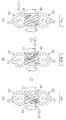
- the description will be given focusing on the spiral groove (41) shaded in FIG. 12, that is, the compression chamber (23).
- the compression chamber (23) with shading communicates with the low-pressure space (S1).
- the spiral groove (41) in which the compression chamber (23) is formed meshes with the gate (51) of the gate rotor (50) located on the lower side of the figure.
- the gate (51) relatively moves toward the terminal end of the spiral groove (41), and the volume of the compression chamber (23) increases accordingly.
- the low-pressure gas refrigerant in the low-pressure space (S1) is sucked into the compression chamber (23) through the suction port (24).
- the compression chamber (23) with shading is completely closed. That is, the spiral groove (41) in which the compression chamber (23) is formed meshes with the gate (51) of the gate rotor (50) located on the upper side of the figure, and the low pressure space ( It is partitioned from S1).
- the gate (51) moves toward the end of the spiral groove (41) as the screw rotor (40) rotates, the volume of the compression chamber (23) gradually decreases. As a result, the gas refrigerant in the compression chamber (23) is compressed.
- the gate (51) After the gate (51) reaches the position where the compression chamber (23) in the spiral groove (41) is completely closed, the side walls (42, 43) of the gate (51) and the spiral groove (41) And the bottom wall surface (44) need not physically rub against each other, and there may be a minute gap between them. That is, even if there are minute gaps between the gate (51) and the side wall surfaces (42, 43) and the bottom wall surface (44) of the spiral groove (41), the gap can be sealed with an oil film made of lubricating oil. If it is a thing, the airtightness of a compression chamber (23) is maintained, and the quantity of the gas refrigerant
- FIG. 1 (B) shows a state opening to the first and second depressions (74, 75) (that is, a state communicating with the first and second discharge passages (17a, 17b)), and FIG. 1 (C).
- the state changes to a state where only the second depressed portion (75) shown (ie, a state communicating with the second discharge passage (17b)) is opened. Thereafter, the spiral groove (41) does not open to the second depression (75).
- the fixed port (18) Open to. That is, by providing the fixed port (18), it is possible to delay the spiral groove (41) from being completely opened as much as possible and to discharge the gas refrigerant from the spiral groove (41) as much as possible. Yes.
- the screw rotor (40) immediately after the spiral groove (41) opens to the first depression (74), that is, immediately after the spiral groove (41b) opens to the first port (74b).
- the spiral groove (41) adjacent to the front side in the rotation direction (traveling side) has not yet detached from the second port (75b) and is open to the second port (75b).
- the spiral groove (41) (41) that has been opened earlier has almost completely discharged the refrigerant gas, and the pressure has dropped to the discharge port (73) compared to immediately after opening.
- the spiral groove immediately after the opening (hereinafter also referred to as the later spiral groove) (41) is in a state where the refrigerant gas is most compressed and in a high pressure state.
- the discharge port (73) is divided into the first port (74b) and the second port (75b) by the partition wall (76).
- the front end surface of the partition wall (76) and the inner peripheral surface of the cylindrical wall (11) form a cylindrical inner peripheral surface with which the tooth tips of the screw rotor (40) are in sliding contact with each other.
- the two ports (75b) open independently from the screw rotor storage chamber (12).
- the partition wall (76) is such that when the two adjacent spiral grooves (41, 41) are simultaneously open to the discharge port (73), the subsequent spiral groove (41) is open only to the first port (74b).
- the spiral groove (41) is provided at a position that opens only to the second port (75b).
- the previous spiral groove (41) opens only to the second port (75b) and does not open to the first port (74b).
- the rear spiral groove (41) opens only to the first port (74b) and does not open to the second port (74b). Therefore, the gas refrigerant discharged from the rear spiral groove (41) to the first port (74b) flows through the first discharge passage (17a) and flows out to the high-pressure space (S2).
- the gas refrigerant discharged from the spiral groove (41) to the second port (75b) flows through the second discharge passage (17b) and flows out into the high-pressure space (S2).
- the discharge port (73) is divided into the first port (74b) and the second port (75b) by the partition wall (76), the high pressure of the later spiral groove (41) Can be prevented from propagating to the spiral groove (41) and increasing the discharge work of the screw compressor (1).
- the slide valve (7) has a first port (74b), a second port (75b), and a partition wall depending on the position. Since the position of (76) also changes (see FIG. 10), it is possible to reliably prevent the preceding spiral groove (41) and the subsequent spiral groove (41) from opening simultaneously in the same discharge port (73). it can.
- the slide valve (7) closed the bypass port (19a) (that is, the tip surface (71c) of the valve body (71) is in close contact with the opening end surface (16c) of the opening (16)).
- a part of the refrigerant can be bypassed to the low-pressure space (S1) by moving the slide valve (7) to the high-pressure space (S2) in the axial direction.
- the first and second ports (74b, 75b) move in parallel in the axial direction as shown in FIG.
- the timing at which the spiral groove (41) opens to the discharge port (73), specifically, the first port (74b) simply changes.
- the timing at which the spiral groove (41) is detached from the discharge port (73) does not change even if the slide valve (7) moves. That is, the spiral groove (41) finally opens at the fixed port (18) and moves away from it.
- the end of the partition wall (76) on the front side in the rotational direction of the screw rotor (40) is located in the fixed port (18), and the first port (74b) and the second port (75b) are connected to the fixed port ( 18) may communicate via
- the opening timing of the spiral groove (41) to the discharge port (73) is delayed, when the subsequent spiral groove (41) opens to the first port (74b), the preceding spiral groove (41) gets closer to the state of being detached from the discharge port (73), and the opening area of the spiral groove (41) to the second port (75b) is smaller than that under high load.
- the opening area of the fixed port (18) to the first depression (74) and the second depression (75) is very small. Therefore, the influence of the communication between the first port (74b) and the second port (75b) via the fixed port (18) is small. Even in such a case, the partition wall (76) is provided, By dividing the first port (74b) and the second port (75b), it is possible to suppress the propagation of pressure from the subsequent spiral groove (41) to the preceding spiral groove (41). If you want to suppress the propagation of pressure through the fixed port (18), the bulkhead (76) is fixed even when the slide valve (7) is moved most to the high-pressure space (S2). What is necessary is just to set the shape of a partition (76) and the shape of a notch part (18a) so that it may not be located in a port (18) (it does not reach
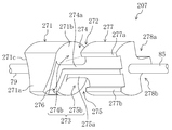
- Embodiment 2 of the Invention ⁇ Embodiment 2 of the Invention >> Next, a slide valve according to Embodiment 2 of the present invention will be described.
- the slide valve (207) according to the second embodiment is different from the first embodiment in the configuration of the port portion.
- Other configurations of the screw compressor are the same as those in the first embodiment. Therefore, the same configurations as those of the first embodiment are denoted by the same reference numerals, and the description thereof is omitted, and different configurations are mainly described.
- the partition wall (276) is formed in a substantially L shape at the port portion (272).
- the partition wall (276) is inclined from the front side (traveling side, lower side in FIG. 12) of the screw rotor (40) toward the rear side (front side, upper side in FIG. 12).
- the slide valve (207) is bent in the axial direction and extends in the axial direction.
- the port portion (272) is formed with a first depressed portion (274) and a second depressed portion (275) that are depressed radially inward from the concave curved surface (271a) of the valve body (271). .
- the first depressed portion (274) extends from between the inclined surface (271b) of the valve body (271) and the partition wall (276) to the region of the partition wall (276) on the rear side in the rotational direction of the screw rotor (40). Is formed.
- a first port (274b) is formed on the recessed surface (274a) of the first recessed portion (274), as in the first embodiment.
- the first port (274b) is formed in a groove shape by radially cutting a cylindrical side surface portion between the first depression (274) and the first notch (278a) on the back side.
- the first depression (274) and the first notch (278a) are communicated with each other.
- the second depression (275) is formed in a region of the partition wall (276) on the front side in the rotational direction of the screw rotor (40).
- a second port (275b) is formed on the depressed surface (275a) of the second depressed portion (275), as in the first embodiment.
- the second port (275b) is formed in a groove shape by radially notching a cylindrical side surface portion between the second depression (275) and the second notch (278b) on the back side.
- the second depression (275) and the second notch (278b) are in communication.
- first depression (274) and the second depression (275) are isolated by the partition wall (276). That is, the discharge port (273) is separated from the first port (274b) and the second port (275b) by the partition wall (276).
- the partition wall (276), the recessed surface (274a) of the first recessed portion (274), and the recessed surface (275a) of the second recessed portion (275) extend to the guide portion (277).
- the guide portion (277) extends in the axial direction of the screw rotor (40) at the rear edge in the rotational direction of the screw rotor (40) of the recessed surface (274a) of the first recessed portion (274) and The first guide portion (277a) protruding from the recessed surface (274a) and the screw rotor (40) at the front edge in the rotational direction of the screw rotor (40) of the recessed surface (275a) of the second recessed portion (275) A second guide portion (277b) extending in the axial direction and protruding from the recessed surface (275a) is formed.
- the protruding end surfaces of the first guide portion (277a) and the second guide portion (277b) and the protruding end surface of the partition wall (276) are curved in the same manner as the concave curved surface (271a) of the valve body (271).
- the inner peripheral surface of the same cylinder is formed together with the concave curved surface (271a). That is, the portion of the partition wall (276) positioned at the port portion (272) is in sliding contact with the outer peripheral surface of the screw rotor (40) together with the concave curved surface (271a) of the valve body (271).
- the part located in the guide part (277) of the partition wall (276) and the first guide part (277a) and the second guide part (277b) are configured to be in sliding contact with the outer peripheral surface of the bearing holder (60). Has been.
- the slide valve (207) configured in this manner is housed in the slide valve housing chamber (14) as in the first embodiment, and constitutes the discharge port (73) of the compression mechanism (20).
- the refrigerant gas discharged from the compression chamber (23) is discharged from the first and second discharge passages (17a, 17b) via the first and second ports (274b, 275b).
- a part of the refrigerant gas is formed by the first guide part (277a), the partition wall (276), and the bearing holder (60), and a second guide part. (277b), the partition wall (276), and the bearing holder (60) pass through the passage formed and flow out into the high-pressure space (S2).
- slide valve (207) according to the second embodiment can provide the same operations and effects as the first embodiment.
- the present invention is useful for a screw compressor in which two adjacent spiral grooves may open simultaneously to the discharge port.
Abstract
A screw compressor operating with compression efficiency which does not decrease when two adjacent helical grooves simultaneously open to a discharge port. The screw compressor (1) has a screw rotor (40), a casing (10) for housing the screw rotor (40) and having the discharge port formed in the inner peripheral surface of the casing, and gate rotors (50) having gates (51, 51, ...) meshing with helical grooves (41) of the screw rotor (40). A compression chamber (23) formed by the screw rotor (40), the casing (10), and the gate rotors (50) compresses gas and discharges the compressed gas from the discharge port. The discharge port is dividedinto a first port (74b) and a second port (75b) which are adapted such that, when two adjacent helical grooves (41, 41) of the helical grooves (41) open to the discharge port as the screw rotor (40) rotates, one of the two adjacent helical grooves (41, 41) opens to the first port (74b) and the other to the second port (75b).
Description
本発明は、スクリュー圧縮機に関するものである。
The present invention relates to a screw compressor.
従来より、冷媒や空気等のガスを圧縮する圧縮機として、1つのスクリューロータと該スクリューロータを収容するケーシングと2つのゲートロータとを備えたシングルスクリュー圧縮機が知られている(特許文献1参照)。
Conventionally, as a compressor for compressing a gas such as refrigerant or air, a single screw compressor including one screw rotor, a casing for housing the screw rotor, and two gate rotors is known (Patent Document 1). reference).
このスクリュー圧縮機は、スクリューロータの螺旋溝とケーシングとゲートロータのゲートとで区画される閉空間により圧縮室を形成している。スクリュー圧縮機は、スクリューロータを回転させることによってゲートがスクリューロータの螺旋溝内を相対的に移動して圧縮室内のガスを圧縮する。そして、ケーシングには、スクリューロータの螺旋溝の終端近傍に対応する位置に吐出ポートが設けられており、スクリューロータの回転に伴って螺旋溝が吐出ポートに開口することによって、圧縮された高圧ガスが吐出ポートから吐出される。
特開2005-90293号公報
This screw compressor forms a compression chamber by a closed space defined by a spiral groove of a screw rotor, a casing, and a gate of a gate rotor. In the screw compressor, by rotating the screw rotor, the gate relatively moves in the spiral groove of the screw rotor and compresses the gas in the compression chamber. The casing is provided with a discharge port at a position corresponding to the vicinity of the end of the spiral groove of the screw rotor, and the helical groove opens to the discharge port as the screw rotor rotates, thereby compressing the high-pressure gas. Is discharged from the discharge port.
JP 2005-90293 A
ところで、吐出ポートの大きさや螺旋溝の幅や隣接する螺旋溝の間隔等によっては、隣接する2つの螺旋溝が同時に吐出ポートに開口する場合がある。すなわち、先に吐出ポートに開口していた螺旋溝が吐出ポートから外れる(吐出ポートに開口しなくなる)直前に、次の螺旋溝が吐出ポートに開口する場合がある。
By the way, depending on the size of the discharge port, the width of the spiral groove, the interval between adjacent spiral grooves, and the like, two adjacent spiral grooves may open to the discharge port at the same time. That is, the next spiral groove may open to the discharge port immediately before the spiral groove previously opened to the discharge port is removed from the discharge port (no longer opened to the discharge port).
このとき、先の螺旋溝は吐出が略完了してその内部圧力が吐出直後に比べて低くなっているのに対し、後の螺旋溝は吐出の開始直後であってその内部圧力は高くなっている。そのため、後の螺旋溝の吐出直後の圧力が先の螺旋溝に伝播し、吐出仕事を増加させて、圧縮機効率を低下させる虞がある。
At this time, the first spiral groove is almost completely discharged and its internal pressure is lower than that immediately after discharge, whereas the latter spiral groove is immediately after the start of discharge and its internal pressure is high. Yes. For this reason, the pressure immediately after the discharge of the subsequent spiral groove propagates to the previous spiral groove, which may increase the discharge work and reduce the compressor efficiency.
本発明は、かかる点に鑑みてなされたものであり、その目的とするところは、隣接する2つの螺旋溝が同時に吐出ポートに開口することによる圧縮機効率の低下を防止することにある。
The present invention has been made in view of such a point, and an object of the present invention is to prevent a reduction in compressor efficiency due to two adjacent spiral grooves opening simultaneously into the discharge port.
第1の発明は、複数の螺旋溝(41,41,…)が形成されたスクリューロータ(40)と、該スクリューロータ(40)を収容すると共にその内周面に吐出ポートが設けられたケーシング(10)と、該スクリューロータ(40)の螺旋溝(41,41,…)に噛合するゲート(51,51,…)を有するゲートロータ(50)とを備え、該螺旋溝(41,41,…)と該ケーシング(10)と該ゲート(51,51,…)とで形成される圧縮室(23,23,…)でガスを圧縮して該吐出ポート(73,73)から吐出するスクリュー圧縮機が対象である。そして、上記吐出ポート(73)は、上記スクリューロータ(40)の回転に伴って上記螺旋溝(41,41,…)のうち隣接する2つの螺旋溝(41,41)が該吐出ポートに開口する状態になったときに一方の螺旋溝(41)が開口する第1ポート(74b)と他方の螺旋溝(41)が開口する第2ポート(75b)とに分割されているものとする。
The first invention includes a screw rotor (40) in which a plurality of spiral grooves (41, 41,...) Are formed, and a casing that houses the screw rotor (40) and is provided with a discharge port on the inner peripheral surface thereof. (10) and a gate rotor (50) having a gate (51, 51,...) Meshing with the spiral groove (41, 41,...) Of the screw rotor (40). , ...), the casing (10), and the gate (51,51, ...) are compressed in a compression chamber (23,23, ...) and discharged from the discharge port (73,73). The target is screw compressors. The discharge port (73) has two adjacent spiral grooves (41, 41) of the spiral grooves (41, 41,...) Opened to the discharge port as the screw rotor (40) rotates. It is assumed that the first port (74b) in which one of the spiral grooves (41) is opened and the second port (75b) in which the other spiral groove (41) is opened are divided.
上記の構成の場合、隣接する2つの螺旋溝(41,41)が吐出ポート(73)に同時に開口したとしても、該吐出ポート(73)がそれぞれ第1ポート(74b)と第2ポート(75b)とに分割されているため、吐出ポート(73)に開口直後の螺旋溝(41)から、吐出ポート(73)から外れる直前の螺旋溝(41)へ、吐出圧力が伝播することが抑制される。その結果、スクリュー圧縮機の吐出仕事が増大することを抑制することができ、圧縮機効率を向上させることができる。
In the case of the above configuration, even if two adjacent spiral grooves (41, 41) are simultaneously opened to the discharge port (73), the discharge port (73) is respectively connected to the first port (74b) and the second port (75b). ), The discharge pressure is suppressed from propagating from the spiral groove (41) immediately after opening to the discharge port (73) to the spiral groove (41) immediately before coming out of the discharge port (73). The As a result, an increase in discharge work of the screw compressor can be suppressed, and the compressor efficiency can be improved.
尚、吐出ポート(73)に1つの螺旋溝(41)だけが開口するときには、該螺旋溝(41)は第1及び第2ポート(74b,75b)に跨って、又は第1及び第2ポート(74b,75b)の何れかだけに開口し得る。
When only one spiral groove (41) opens in the discharge port (73), the spiral groove (41) straddles the first and second ports (74b, 75b) or the first and second ports. Only one of (74b, 75b) can be opened.
第2の発明は、第1の発明において、上記ケーシング(10)には、開口部(16)が形成されており、上記ケーシング(10)の該開口部(16)内に配設されたスライドバルブ(7)をさらに備え、上記スライドバルブ(7)には、上記第1及び第2ポート(74b,75b)並びに該第1ポート(74b)と該第2ポート(75b)とを分割する隔壁(76)が設けられているものとする。
According to a second invention, in the first invention, the casing (10) is formed with an opening (16), and the slide disposed in the opening (16) of the casing (10). The slide valve (7) further includes a valve (7), and the first and second ports (74b, 75b) and a partition that divides the first port (74b) and the second port (75b) (76) shall be provided.
上記の構成の場合、スライドバルブ(7)の移動によって吐出ポート(73)の位置が変化し、隣接する2つの螺旋溝(41,41)が吐出ポート(73)に同時に開口するタイミングも変化する。そこで、吐出ポート(73)を構成するスライドバルブ(7)に、吐出ポート(73)を第1ポート(74b)と第2ポート(75b)とに分割する隔壁(76)を設けることによって、隣接する2つの螺旋溝(41,41)が吐出ポート(73)に同時に開口するタイミングが変化しても、それに合わせて、隔壁(76)の位置を変更することができ、吐出ポート(73)に開口直後の螺旋溝(41)から、吐出ポート(73)から外れる直前の螺旋溝(41)へ、吐出圧力が伝播することを確実に抑制することができる。
In the case of the above configuration, the position of the discharge port (73) is changed by the movement of the slide valve (7), and the timing at which the two adjacent spiral grooves (41, 41) are simultaneously opened to the discharge port (73) also changes. . Therefore, the slide valve (7) constituting the discharge port (73) is provided with a partition wall (76) that divides the discharge port (73) into a first port (74b) and a second port (75b). Even if the timing at which the two spiral grooves (41, 41) simultaneously open to the discharge port (73) changes, the position of the partition wall (76) can be changed accordingly, and the discharge port (73) Propagation of the discharge pressure from the spiral groove (41) immediately after the opening to the spiral groove (41) immediately before coming off from the discharge port (73) can be reliably suppressed.
第3の発明は、第1又は第2の発明において、上記ケーシング(10)には、上記吐出ポート(73,73の下流側において該吐出ポート(73,73)に連通する吐出通路(17,17)が形成されており、上記吐出通路(17)は、上記第1ポート(74b)と連通する第1吐出通路(17a)と、上記第2ポート(75b)と連通する第2吐出通路(17b)とに分割されているものとする。
According to a third invention, in the first or second invention, the casing (10) has a discharge passage (17, 73) communicating with the discharge port (73, 73) on the downstream side of the discharge port (73, 73). 17) is formed, and the discharge passage (17) includes a first discharge passage (17a) communicating with the first port (74b) and a second discharge passage (communication with the second port (75b)). 17b).
上記の構成の場合、第1及び第2ポート(74b,75b)の下流側において該第1及び第2ポート(74b,75b)にそれぞれ連通する第1及び第2吐出通路(17a,17b)を分割することによって、ガスが第1及び第2ポート(74b,75b)からそれぞれ第1及び第2吐出通路(17a,17b)へ流出した後も直ちには合流しないため、吐出ポート(73)に開口直後の螺旋溝(41)から、吐出ポート(73)から外れる直前の螺旋溝(41)へ、吐出圧力が伝播することをさらに確実に抑制することができる。
In the case of the above configuration, the first and second discharge passages (17a, 17b) communicating with the first and second ports (74b, 75b) on the downstream side of the first and second ports (74b, 75b), respectively. By dividing, the gas does not immediately merge after flowing out from the first and second ports (74b, 75b) to the first and second discharge passages (17a, 17b), respectively. Propagation of the discharge pressure from the immediately following spiral groove (41) to the spiral groove (41) just before detaching from the discharge port (73) can be further reliably suppressed.
本発明によれば、吐出ポート(73)を、隣接する2つの螺旋溝(41,41)が該吐出ポート(73)に開口するときの一方の螺旋溝(41)が開口する第1ポート(74b)と他方の螺旋溝(41)が開口する第2ポート(75b)とに分割することによって、吐出ポート(73)に開口直後の螺旋溝(41)からの吐出圧力が開口しなくなる直前の螺旋溝(41)に伝播することが抑制されるため、吐出仕事を低減させることができ、圧縮機効率を向上させることができる。
According to the present invention, the discharge port (73) is connected to the first port (one spiral groove (41) opened when two adjacent spiral grooves (41, 41) open to the discharge port (73)). 74b) and the second port (75b) in which the other spiral groove (41) is opened, the discharge pressure from the spiral groove (41) immediately after opening to the discharge port (73) Since propagation to the spiral groove (41) is suppressed, discharge work can be reduced and compressor efficiency can be improved.
第2の発明によれば、吐出ポート(73)を第1及び第2ポート(74b,75b)並びに第1ポート(74b)と第2ポート(75b)とを分割する隔壁(76)をスライドバルブ(7)に設けることによって、スライドバルブ(7)の位置が変更されることで隣接する2つの螺旋溝(41,41)が吐出ポート(73)に同時に開口するタイミングが変化したとしても、吐出ポート(73)に開口直後の螺旋溝(41)からの吐出圧力が吐出ポート(73)から外れる直前の螺旋溝(41)に伝播することを抑制することができる。
According to the second invention, the discharge port (73) has the first and second ports (74b, 75b), and the partition wall (76) dividing the first port (74b) and the second port (75b) has a slide valve. Even if the timing at which the two adjacent spiral grooves (41, 41) are simultaneously opened to the discharge port (73) is changed by changing the position of the slide valve (7), Propagation of the discharge pressure from the spiral groove (41) immediately after opening to the port (73) to the spiral groove (41) immediately before coming out of the discharge port (73) can be suppressed.
第3の発明によれば、吐出ポート(73)に連通する吐出通路(17)を第1ポート(74b)に連通する第1吐出通路(17a)と第2ポート(75b)に連通する第2吐出通路(17b)とに分割することによって、吐出ポート(73)に開口直後の螺旋溝(41)からの吐出圧力が吐出ポート(73)から外れる直前の螺旋溝(41)に伝播することを確実に抑制することができる。
According to the third aspect of the invention, the discharge passage (17) communicating with the discharge port (73) communicates with the first discharge passage (17a) communicating with the first port (74b) and the second port (75b). By dividing into the discharge passage (17b), the discharge pressure from the spiral groove (41) immediately after opening to the discharge port (73) is propagated to the spiral groove (41) just before coming out of the discharge port (73). It can be surely suppressed.
1 シングルスクリュー圧縮機(スクリュー圧縮機)
10 ケーシング
16 開口部
17a 第1吐出通路
17b 第2吐出通路
23 圧縮室
40 スクリューロータ
41 螺旋溝
50 ゲートロータ
51 ゲート
7,207 スライドバルブ
73,273 吐出ポート
74b,274b 第1ポート
75b,275b 第2ポート
76,276 隔壁 1 Single screw compressor (screw compressor)
10casing 16 opening 17a first discharge passage 17b second discharge passage 23 compression chamber 40 screw rotor 41 spiral groove 50 gate rotor 51 gate 7,207 slide valve 73,273 discharge port 74b, 274b first port 75b, 275b second port 76,276 partition
10 ケーシング
16 開口部
17a 第1吐出通路
17b 第2吐出通路
23 圧縮室
40 スクリューロータ
41 螺旋溝
50 ゲートロータ
51 ゲート
7,207 スライドバルブ
73,273 吐出ポート
74b,274b 第1ポート
75b,275b 第2ポート
76,276 隔壁 1 Single screw compressor (screw compressor)
10
以下、本発明の実施形態を図面に基づいて詳細に説明する。
Hereinafter, embodiments of the present invention will be described in detail with reference to the drawings.
《発明の実施形態1》
本発明の実施形態1に係るスクリュー圧縮機(1)は、冷凍サイクルを行う冷媒回路に設けられて冷媒を圧縮するためのものである。スクリュー圧縮機(1)は、図2,3に示すように、半密閉型に構成されている。このスクリュー圧縮機(1)では、圧縮機構(20)とそれを駆動する電動機(図示省略)とが1つのケーシング(10)に収容されている。圧縮機構(20)は、駆動軸(21)を介して電動機と連結されている。また、ケーシング(10)内には、冷媒回路の蒸発器から低圧のガス冷媒が導入されると共に該低圧ガスを圧縮機構(20)へ案内する低圧空間(S1)と、圧縮機構(20)から吐出された高圧のガス冷媒が流入する高圧空間(S2)とが区画形成されている。Embodiment 1 of the Invention
The screw compressor (1) which concerns onEmbodiment 1 of this invention is provided in the refrigerant circuit which performs a refrigerating cycle, and is for compressing a refrigerant | coolant. As shown in FIGS. 2 and 3, the screw compressor (1) is configured as a semi-hermetic type. In the screw compressor (1), a compression mechanism (20) and an electric motor (not shown) for driving the compression mechanism (20) are accommodated in one casing (10). The compression mechanism (20) is connected to the electric motor via the drive shaft (21). Further, in the casing (10), a low-pressure gas refrigerant is introduced from the evaporator of the refrigerant circuit and the low-pressure space (S1) for guiding the low-pressure gas to the compression mechanism (20), and the compression mechanism (20) A high-pressure space (S2) into which the discharged high-pressure gas refrigerant flows is partitioned.
本発明の実施形態1に係るスクリュー圧縮機(1)は、冷凍サイクルを行う冷媒回路に設けられて冷媒を圧縮するためのものである。スクリュー圧縮機(1)は、図2,3に示すように、半密閉型に構成されている。このスクリュー圧縮機(1)では、圧縮機構(20)とそれを駆動する電動機(図示省略)とが1つのケーシング(10)に収容されている。圧縮機構(20)は、駆動軸(21)を介して電動機と連結されている。また、ケーシング(10)内には、冷媒回路の蒸発器から低圧のガス冷媒が導入されると共に該低圧ガスを圧縮機構(20)へ案内する低圧空間(S1)と、圧縮機構(20)から吐出された高圧のガス冷媒が流入する高圧空間(S2)とが区画形成されている。
The screw compressor (1) which concerns on
圧縮機構(20)は、1つのスクリューロータ(40)と、ケーシング(10)の一部を構成し且つ該スクリューロータ(40)を収容するスクリューロータ収容室(12)を区画形成する円筒壁(11)と、該スクリューロータ(40)に噛み合う2つのゲートロータ(50)とを備えている。
The compression mechanism (20) includes one screw rotor (40) and a cylindrical wall (10) that forms a part of the casing (10) and that defines a screw rotor housing chamber (12) that houses the screw rotor (40). 11) and two gate rotors (50) meshing with the screw rotor (40).
スクリューロータ(40)には、駆動軸(21)が挿通されている。スクリューロータ(40)と駆動軸(21)は、キー(22)によって連結されている。駆動軸(21)は、スクリューロータ(40)と同軸上に配置されている。駆動軸(21)の先端部は、圧縮機構(20)の高圧空間(S2)側(図2における駆動軸(21)の軸方向を左右方向とした場合の右側)に位置する軸受ホルダ(60)に回転自在に支持されている。この軸受ホルダ(60)は、玉軸受(61)を介して駆動軸(21)を支持している。
The drive shaft (21) is inserted through the screw rotor (40). The screw rotor (40) and the drive shaft (21) are connected by a key (22). The drive shaft (21) is arranged coaxially with the screw rotor (40). The tip of the drive shaft (21) is a bearing holder (60) located on the high pressure space (S2) side of the compression mechanism (20) (right side when the axial direction of the drive shaft (21) in FIG. 2 is the left-right direction). ) Is rotatably supported. The bearing holder (60) supports the drive shaft (21) via a ball bearing (61).
図4,5に示すように、スクリューロータ(40)は、概ね円柱状に形成された金属製の部材である。スクリューロータ(40)は、円筒壁(11)に回転可能に嵌合しており、その外周面が円筒壁(11)の内周面と摺接する。スクリューロータ(40)の外周部には、スクリューロータ(40)の一端から他端へ向かって螺旋状に延びる螺旋溝(41,41,…)が複数形成されている。
As shown in FIGS. 4 and 5, the screw rotor (40) is a metal member formed in a substantially cylindrical shape. The screw rotor (40) is rotatably fitted to the cylindrical wall (11), and the outer peripheral surface thereof is in sliding contact with the inner peripheral surface of the cylindrical wall (11). A plurality of spiral grooves (41, 41,...) Extending spirally from one end to the other end of the screw rotor (40) are formed on the outer peripheral portion of the screw rotor (40).
スクリューロータ(40)の各螺旋溝(41)は、該スクリューロータ(40)の軸方向における一端側(図5における左側)が始端となり、他端側(図5における右側)が終端となっている。また、スクリューロータ(40)は、軸方向一端面の周縁部がテーパー面に形成されている。そして、螺旋溝(41)の始端はテーパー面に開口する一方、螺旋溝(41)の終端はスクリューロータ(40)の外周面に開口し軸方向他端面には開口していない。
Each spiral groove (41) of the screw rotor (40) starts at one end side (left side in FIG. 5) in the axial direction of the screw rotor (40) and ends at the other end side (right side in FIG. 5). Yes. The screw rotor (40) has a tapered peripheral surface at one end surface in the axial direction. The starting end of the spiral groove (41) opens to the tapered surface, while the end of the spiral groove (41) opens to the outer peripheral surface of the screw rotor (40) and does not open to the other end surface in the axial direction.
螺旋溝(41)は、ゲートロータ(50)の後述するゲート(51)の進行方向の前側に位置する第1側壁面(42)と、ゲート(51)の進行方向の後側に位置する第2側壁面(43)と、底壁面(44)とで構成されている。
The spiral groove (41) has a first side wall surface (42) positioned on the front side in the moving direction of the gate (51) described later of the gate rotor (50) and a rear side in the moving direction of the gate (51). It consists of two side wall surfaces (43) and a bottom wall surface (44).
各ゲートロータ(50)は、長方形板状に形成された複数のゲート(51)が放射状に設けられた樹脂製の部材である。各ゲートロータ(50)は、円筒壁(11)の外側にスクリューロータ(40)の回転軸に対して軸対称に配置されたゲートロータ収容室(13)内に収容されている(図3を参照)。ゲートロータ収容室(13)とスクリューロータ収容室(12)とは、円筒壁(11)に形成されたスリット(図示省略)を介して連通しており、各ゲートロータ(50)は、ゲート(51,51,…)が円筒壁(11)のスリットを貫通してスクリューロータ(40)の螺旋溝(41,41,…)に噛み合うように配置されている。
Each gate rotor (50) is a resin member provided with a plurality of gates (51) formed in a rectangular plate shape radially. Each gate rotor (50) is accommodated in a gate rotor accommodating chamber (13) which is arranged outside the cylindrical wall (11) and symmetrical about the rotational axis of the screw rotor (40) (see FIG. 3). reference). The gate rotor storage chamber (13) and the screw rotor storage chamber (12) communicate with each other through a slit (not shown) formed in the cylindrical wall (11). Each gate rotor (50) 51, 51,... Are arranged so as to penetrate the slits of the cylindrical wall (11) and engage with the spiral grooves (41, 41,...) Of the screw rotor (40).
ゲートロータ(50)は、金属製のロータ支持部材(55)に取り付けられている(図4を参照)。ロータ支持部材(55)は、基部(56)とアーム部(57)と軸部(58)とを備えている。基部(56)は、やや肉厚の円板状に形成されている。アーム部(57)は、ゲートロータ(50)のゲート(51)と同数だけ設けられており、基部(56)の外周面から外側へ向かって放射状に延びている。軸部(58)は、棒状に形成されて基部(56)に立設されている。軸部(58)の中心軸は、基部(56)の中心軸と一致している。ゲートロータ(50)は、基部(56)及びアーム部(57)における軸部(58)とは反対側の面に取り付けられている。各アーム部(57)は、ゲート(51)の裏面(背面ともいう)に当接している。
The gate rotor (50) is attached to a metal rotor support member (55) (see FIG. 4). The rotor support member (55) includes a base portion (56), an arm portion (57), and a shaft portion (58). The base (56) is formed in a slightly thick disk shape. The same number of arms (57) as the gates (51) of the gate rotor (50) are provided and extend radially outward from the outer peripheral surface of the base (56). The shaft portion (58) is formed in a rod shape and is erected on the base portion (56). The central axis of the shaft portion (58) coincides with the central axis of the base portion (56). The gate rotor (50) is attached to a surface of the base portion (56) and the arm portion (57) opposite to the shaft portion (58). Each arm portion (57) is in contact with the back surface (also referred to as the back surface) of the gate (51).
2つのゲートロータ(50,50)は、ゲートロータ収容室(13)内において、その軸心がスクリューロータ(40)の軸心を含む平面に対して直交するように配設されている。このとき、各ゲートロータ(50)は、スクリューロータ(40)の螺旋溝(41)に噛合した状態において、その表面がスクリューロータ(40)の回転方向に対向するように配設されている。すなわち、各ゲートロータ(50)は、軸部(58)がスクリューロータ(40)の回転方向の接線方向に延びるように配設されている。その結果、2つの軸部(58,58)は、スクリューロータ(40)の軸心を含む平面を挟んで互いに反対方向に延びている。すなわち、図3においては、左側に配置されたゲートロータ(50)は、ロータ支持部材(55)が下方を向く姿勢で設置される一方、右側に配置されたゲートロータ(50)は、ロータ支持部材(55)が上方を向く姿勢で設置されている。各ロータ支持部材(55)の軸部(58)は、ゲートロータ収容室(13)内の軸受ハウジング(13a)に玉軸受(13b,13b)を介して回転自在に支持されている。
The two gate rotors (50, 50) are arranged in the gate rotor accommodating chamber (13) so that the axis thereof is orthogonal to the plane including the axis of the screw rotor (40). At this time, each gate rotor (50) is arranged so that the surface thereof faces the rotational direction of the screw rotor (40) in a state where the gate rotor (50) meshes with the spiral groove (41) of the screw rotor (40). That is, each gate rotor (50) is arrange | positioned so that a axial part (58) may extend in the tangential direction of the rotation direction of a screw rotor (40). As a result, the two shaft portions (58, 58) extend in directions opposite to each other across a plane including the axis of the screw rotor (40). That is, in FIG. 3, the gate rotor (50) disposed on the left side is installed with the rotor support member (55) facing downward, while the gate rotor (50) disposed on the right side is supported by the rotor. The member (55) is installed in a posture facing upward. The shaft portion (58) of each rotor support member (55) is rotatably supported by a bearing housing (13a) in the gate rotor accommodating chamber (13) via ball bearings (13b, 13b).
圧縮機構(20)では、円筒壁(11)の内周面と、スクリューロータ(40)の螺旋溝(41)と、ゲートロータ(50)のゲート(51)とによって囲まれた閉空間が圧縮室(23)になる。スクリューロータ(40)の螺旋溝(41)は、始端部が低圧空間(S1)に開放しており、この開放部分が圧縮機構(20)の吸入ポート(24)になっている。
In the compression mechanism (20), the closed space surrounded by the inner peripheral surface of the cylindrical wall (11), the spiral groove (41) of the screw rotor (40), and the gate (51) of the gate rotor (50) is compressed. It becomes room (23). The spiral groove (41) of the screw rotor (40) has a starting end opened to the low-pressure space (S1), and this open portion serves as a suction port (24) of the compression mechanism (20).
スクリュー圧縮機(1)には、容量制御機構としてスライドバルブ(7)が2つ設けられている。このスライドバルブ(7)は、吐出ポート(73)及びバイパスポート(19a)を構成する。
The screw compressor (1) is provided with two slide valves (7) as a capacity control mechanism. The slide valve (7) constitutes a discharge port (73) and a bypass port (19a).
スライドバルブ(7)は、図6に示すように、円柱を基本形状とし、該円柱の一部を切削した形状をしていて、軸方向一側に設けられたバルブ本体(71)と、軸方向他側に設けられたガイド部(77)と、バルブ本体(71)とガイド部(77)との間に設けられたポート部(72)とを有する。
As shown in FIG. 6, the slide valve (7) has a cylindrical shape as a basic shape, a shape obtained by cutting a part of the cylindrical shape, and a valve body (71) provided on one side in the axial direction, It has a guide part (77) provided on the other side in the direction, and a port part (72) provided between the valve body (71) and the guide part (77).
上記バルブ本体(71)は、円柱の外周面の一部を軸方向に切り欠いて形成された凹曲面(71a)と、ポート部(72)との境界面であって軸方向に対して傾斜した傾斜面(71b)と、該傾斜面(71b)と軸方向反対側の面であって軸方向に対して直交する平面に形成された先端面(71c)とを有している。
The valve body (71) is a boundary surface between the concave curved surface (71a) formed by cutting out a part of the outer peripheral surface of the cylinder in the axial direction and the port portion (72) and is inclined with respect to the axial direction. The inclined surface (71b), and the tip surface (71c) formed on a plane that is opposite to the inclined surface (71b) in the axial direction and orthogonal to the axial direction.
凹曲面(71a)は、径方向内側に凹陥していると共に、円筒壁(11)の内周面と略同じ曲率、即ち、スクリューロータ(40)の外周面の曲率と略同じ曲率を有する。
The concave curved surface (71a) is recessed radially inward and has substantially the same curvature as the inner peripheral surface of the cylindrical wall (11), that is, substantially the same curvature as the outer peripheral surface of the screw rotor (40).
傾斜面(71b)は、スライドバルブ(7)を後述するスライドバルブ収容室(14)内に収容した状態において、スクリューロータ(40)の螺旋溝(41)の終端部の(スクリューロータ(40)の軸に対する)傾斜角度と略同様の角度で傾斜している(図1(A)参照)。
In the state where the slide valve (7) is housed in the slide valve housing chamber (14), which will be described later, the inclined surface (71b) is located at the end of the spiral groove (41) of the screw rotor (40) (screw rotor (40) (See FIG. 1 (A)).
このように構成されたバルブ本体(71)は、上記凹曲面(71a)に平行な面で切断した断面が台形状をしている。また、バルブ本体(71)は、軸に直交する断面の形状が、円の一部を別の円の外周の一部で切り欠いた形状をしている。
The valve body (71) configured in this way has a trapezoidal cross section cut along a plane parallel to the concave curved surface (71a). Further, the valve body (71) has a cross-sectional shape orthogonal to the axis, in which a part of a circle is cut out by a part of the outer periphery of another circle.
上記ガイド部(77)は、バルブ本体(71)と同様に、円柱の外周面の一部を軸方向に切り欠いて形成された凹曲面(77a)を有している。この凹曲面(77a)は、径方向内側に凹陥していると共に、円筒壁(11)の内周面と略同じ曲率、即ち、スクリューロータ(40)の外周面の曲率と略同じ曲率を有する。
The guide part (77) has a concave curved surface (77a) formed by cutting out a part of the outer peripheral surface of the cylinder in the axial direction, like the valve body (71). The concave curved surface (77a) is recessed radially inward and has substantially the same curvature as the inner peripheral surface of the cylindrical wall (11), that is, substantially the same curvature as that of the outer peripheral surface of the screw rotor (40). .
また、ガイド部(77)には、軸を挟んで凹曲面(77a)と反対側(以下、背面側ともいう)に、2つの第1及び第2切欠部(78a,78b)が形成されている。第1及び第2切欠部(78a,78b)のそれぞれは、軸方向に延びていて、断面略L字状に切り欠いて形成されている。さらに、ガイド部(77)には、これら2つの第1及び第2切欠部(78a,78b)に挟まれて背面側に突出する背面隔壁(78c)が形成されている。これら第1切欠部(78a)、第2切欠部(78b)及び背面隔壁(78c)は、ポート部(72)にも連続して形成されており、バルブ本体(71)側の端部は傾斜面(71b)まで延びている。こうして、ガイド部(77)は、軸に直交する断面が、概略T字形状をしている。また、ガイド部(77)においては、凹曲面(77a)と第1切欠部(78a)との間の部分、凹曲面(77a)と第2切欠部(78b)との間の部分、及び背面隔壁(78c)の突出端面が円柱の外周面状に形成されている。
The guide portion (77) is formed with two first and second notches (78a, 78b) on the opposite side of the concave curved surface (77a) (hereinafter also referred to as the back side) across the shaft. Yes. Each of the first and second cutout portions (78a, 78b) extends in the axial direction and is formed by cutting out into a substantially L-shaped cross section. Further, the guide part (77) is formed with a back partition wall (78c) that is sandwiched between the two first and second cutout parts (78a, 78b) and protrudes to the back side. The first notch (78a), the second notch (78b), and the rear partition wall (78c) are also formed continuously in the port part (72), and the end on the valve body (71) side is inclined. It extends to the surface (71b). Thus, the guide part (77) has a substantially T-shaped cross section orthogonal to the axis. In the guide portion (77), the portion between the concave curved surface (77a) and the first cutout portion (78a), the portion between the concave curved surface (77a) and the second cutout portion (78b), and the back surface The protruding end surface of the partition wall (78c) is formed in the outer peripheral surface of a cylinder.
上記ポート部(72)は、吐出ポート(73)が形成されている。詳しくは、ポート部(72)は、バルブ本体(71)の凹曲面(71a)と軸方向に隣接して、該凹曲面(71a)よりも径方向内側に陥没した2つの第1及び第2陥没部(74,75)を有している。具体的には、ポート部(72)には、第1陥没部(74)、隔壁(76)、第2陥没部(75)がバルブ本体(71)側から軸方向他端側に向かって順に並んで形成されている。
The discharge port (73) is formed in the port part (72). Specifically, the port portion (72) is adjacent to the concave curved surface (71a) of the valve body (71) in the axial direction, and has two first and second recesses that are recessed radially inward from the concave curved surface (71a). Has depressions (74,75). Specifically, the port part (72) includes a first depression part (74), a partition wall (76), and a second depression part (75) in order from the valve body (71) side toward the other axial end side. It is formed side by side.
上記隔壁(76)は、バルブ本体(71)の傾斜面(71b)と略平行に形成されており、第1陥没部(74)と第2陥没部(75)とを軸方向に隔離している。この隔壁(76)の先端面は、径方向内側に凹陥していると共に、円筒壁(11)の内周面と略同じ曲率、即ち、スクリューロータ(40)の外周面の曲率と略同じ曲率を有する。すなわち、隔壁(76)の先端面、バルブ本体(71)の凹曲面(71a)及びガイド部(77)の凹曲面(77a)は、同一の円筒の内周面を形成する。
The partition wall (76) is formed substantially parallel to the inclined surface (71b) of the valve body (71), and separates the first depression (74) and the second depression (75) in the axial direction. Yes. The front end surface of the partition wall (76) is recessed radially inward and has substantially the same curvature as the inner peripheral surface of the cylindrical wall (11), that is, substantially the same curvature as that of the outer peripheral surface of the screw rotor (40). Have That is, the front end surface of the partition wall (76), the concave curved surface (71a) of the valve body (71) and the concave curved surface (77a) of the guide portion (77) form an inner peripheral surface of the same cylinder.
第1陥没部(74)は、バルブ本体(71)の傾斜面(71b)と隔壁(76)とに挟まれて形成されている。第1陥没部(74)は、底面となる陥没面(74a)を有する。この陥没面(74a)には、背面側に向かって第1ポート(74b)が形成されている。この第1ポート(74b)は、第1陥没部(74)と第1切欠部(78a)との間の円柱部分を径方向に切り欠いて溝状に形成されていて、該第1陥没部(74)と第1切欠部(78a)とを連通させている。
The first depression (74) is formed between the inclined surface (71b) of the valve body (71) and the partition wall (76). The first depressed portion (74) has a depressed surface (74a) serving as a bottom surface. A first port (74b) is formed on the recessed surface (74a) toward the back surface side. The first port (74b) is formed in a groove shape by radially cutting a cylindrical portion between the first depression (74) and the first notch (78a). (74) and the 1st notch (78a) are connected.
一方、第2陥没部(75)は、隔壁(76)によって第1陥没部(74)と軸方向に隔離して形成されている。第2陥没部(75)は、底面となる陥没面(75a)を有する。この陥没面(75a)には、背面側に向かって第2ポート(75b)が貫通形成されている。この第2ポート(75b)は、第2陥没部(75)と第2切欠部(78b)との間の円柱部分を径方向に切り欠いて溝状に形成されていて、該第2陥没部(75)と第2切欠部(78b)とを連通させている。
On the other hand, the second depression (75) is formed to be separated from the first depression (74) in the axial direction by the partition wall (76). The second depressed portion (75) has a depressed surface (75a) serving as a bottom surface. A second port (75b) is formed through the recessed surface (75a) toward the back side. The second port (75b) is formed in a groove shape by notching a cylindrical portion between the second depression (75) and the second notch (78b) in the radial direction. (75) and the 2nd notch (78b) are connected.
また、ポート部(72)は、軸に直交する断面がガイド部(77)と同様に概略T字形状をしている。また、ポート部(72)においては、第2陥没部(75)と第1切欠部(78a)との間の部分、第1陥没部(74)と第2切欠部(78b)との間の部分、及び背面隔壁(78c)の突出端面が、円柱の外周面状に形成されている。
In addition, the port part (72) has a substantially T-shaped cross section orthogonal to the axis, like the guide part (77). Further, in the port portion (72), a portion between the second depressed portion (75) and the first notched portion (78a), and a portion between the first depressed portion (74) and the second notched portion (78b). The part and the projecting end face of the back partition (78c) are formed in the shape of an outer peripheral surface of a cylinder.
また、スライドバルブ(7)は、バルブ本体(71)から軸方向に延びるガイドロッド(79)と、ガイド部(77)から軸方向に延びる連結ロッド(85)とを有している。
The slide valve (7) has a guide rod (79) extending in the axial direction from the valve body (71) and a connecting rod (85) extending in the axial direction from the guide portion (77).
このように構成されたスライドバルブ(7)は、ケーシング(10)の円筒壁(11)に形成されたスライドバルブ収容室(14)内に軸方向にスライド可能に収容されている。スライドバルブ収容室(14)は、図2,3に示すように、円筒壁(11)における、スクリューロータ(40)の軸心を挟んで対称な位置であって、スクリューロータ(40)の螺旋溝(41)の終端部に対応する位置に形成されている。
The slide valve (7) thus configured is accommodated in the slide valve accommodating chamber (14) formed in the cylindrical wall (11) of the casing (10) so as to be slidable in the axial direction. As shown in FIGS. 2 and 3, the slide valve storage chamber (14) is a symmetrical position on the cylindrical wall (11) across the axis of the screw rotor (40), and the spiral of the screw rotor (40). It is formed at a position corresponding to the end portion of the groove (41).
このスライドバルブ収容室(14)は、スクリューロータ(40)の軸方向に延びる空間であって、図7,8に示すように、円筒壁(11)の外側に形成された扇形周壁(15)と該円筒壁(11)によって区画形成されている。尚、図7では、ケーシング(10)のうち円筒壁(11)及び扇形周壁(15)以外の部分は図示を省略している。この扇形周壁(15)は、円筒壁(11)から略径方向外側に延びる2つの側壁(15a,15b)と、これら2つの側壁(15a,15b)の先端を円弧状に繋ぐ円弧壁(15c)を有し、断面略扇形に形成されている。また、円弧壁(15c)には、周方向中央部において径方向内側に突出する軸方向隔壁(15d)が軸方向に延びて形成されている。さらに、円弧壁(15c)には、スライドバルブ(7)がスライドバルブ収容室(14)内へ収容されたときのバルブ本体(71)に対応する位置において径方向内側に突出する周方向隔壁(15f)が周方向に延びて形成されている。この周方向隔壁(15f)は、周方向において一方の側壁(15a)から他方の側壁(15b)まで延びている。また、周方向隔壁(15f)の突出端面(15g)は、バルブ本体(71)の円柱外周面に対応した円筒の内周面形状をしており、スライドバルブ(7)が収容されたときにバルブ本体(71)の円柱外周面と摺接する。上記軸方向隔壁(15d)は、この周方向隔壁(15f)まで延びている。
The slide valve housing chamber (14) is a space extending in the axial direction of the screw rotor (40), and as shown in FIGS. 7 and 8, a fan-shaped peripheral wall (15) formed outside the cylindrical wall (11). And the cylindrical wall (11). In addition, in FIG. 7, parts other than the cylindrical wall (11) and the fan-shaped peripheral wall (15) in the casing (10) are not shown. The fan-shaped peripheral wall (15) has two side walls (15a, 15b) extending substantially radially outward from the cylindrical wall (11), and an arc wall (15c) connecting the tips of the two side walls (15a, 15b) in an arc shape. ) And has a substantially sectoral cross section. The arc wall (15c) is formed with an axial partition wall (15d) that protrudes radially inward at the circumferential central portion so as to extend in the axial direction. Furthermore, the arc wall (15c) has a circumferential partition wall (15) protruding radially inward at a position corresponding to the valve body (71) when the slide valve (7) is housed in the slide valve housing chamber (14). 15f) is formed extending in the circumferential direction. The circumferential partition (15f) extends from one side wall (15a) to the other side wall (15b) in the circumferential direction. The protruding end face (15g) of the circumferential partition wall (15f) has a cylindrical inner peripheral surface shape corresponding to the cylindrical outer peripheral surface of the valve body (71), and when the slide valve (7) is accommodated. It is in sliding contact with the cylindrical outer peripheral surface of the valve body (71). The axial partition (15d) extends to the circumferential partition (15f).
また、円筒壁(11)には、高圧空間(S2)側端面から低圧空間(S1)側へスリット状の開口部(16)が軸方向に延びて形成されている。この開口部(16)は、円筒壁(11)を該円筒壁(11)の径方向に貫通していて、スライドバルブ収容室(14)とスクリューロータ収容室(12)とを連通させている。この開口部(16)を形成する円筒壁(11)の開口端面のうち周方向に対向する2つの開口端面(16a,16b)は、軸方向隔壁(15d)の突出端面(15e)と共に、スライドバルブ収容室(14)内を軸方向に延びる仮想の円筒の内周面を形成している。この仮想の円筒は、スライドバルブ(7)に対応する(即ち、嵌合する)円筒である。
The cylindrical wall (11) is formed with a slit-shaped opening (16) extending in the axial direction from the end surface on the high pressure space (S2) side to the low pressure space (S1) side. The opening (16) passes through the cylindrical wall (11) in the radial direction of the cylindrical wall (11), and allows the slide valve storage chamber (14) and the screw rotor storage chamber (12) to communicate with each other. . Of the opening end faces of the cylindrical wall (11) forming the opening (16), the two opening end faces (16a, 16b) facing in the circumferential direction slide together with the protruding end face (15e) of the axial partition wall (15d). An inner peripheral surface of a virtual cylinder extending in the axial direction in the valve accommodating chamber (14) is formed. This virtual cylinder is a cylinder corresponding to (that is, fitted to) the slide valve (7).
また、円筒壁(11)の開口端面のうち軸方向低圧空間(S1)側の開口端面(16c)は、軸方向に直交する平面に形成されていると共に、スライドバルブ(7)のガイドロッド(79)が嵌合するガイド孔(16d)が軸方向に穿孔されている。
The opening end surface (16c) on the axial low-pressure space (S1) side of the opening end surface of the cylindrical wall (11) is formed in a plane orthogonal to the axial direction, and the guide rod ( 79) is fitted with a guide hole (16d) in the axial direction.
上記スライドバルブ(7)は、高圧空間(S2)側からスライドバルブ収容室(14)内へ、バルブ本体(71)を先頭にして、円筒壁(11)の開口端面(16a,16b)及び円弧壁(15c)の軸方向隔壁(15d)の突出端面(15e)で形成される仮想の円筒内に挿入される。このとき、バルブ本体(71)は、図8に示すように、円柱外周面が円筒壁(11)の開口端面(16a,16b)及び軸方向隔壁(15d)の突出端面(15e)に摺接している。また、ポート部(72)及びガイド部(77)は、第1及び第2陥没部(74,75)並びに凹曲面(77a)と第1切欠部(78a)との間の円柱外周面部分が開口端面(16a)に摺接し、第1及び第2陥没部(74,75)並びに凹曲面(77a)と第2切欠部(78b)との間の円柱外周面部分が開口端面(16b)に摺接し、背面隔壁(78c)の突出端面が軸方向隔壁(15d)の突出端面(15e)に摺接している。
The slide valve (7) has an open end surface (16a, 16b) and a circular arc on the cylindrical wall (11), with the valve body (71) at the top, from the high-pressure space (S2) side into the slide valve storage chamber (14). The wall (15c) is inserted into a virtual cylinder formed by the protruding end surface (15e) of the axial partition wall (15d). At this time, as shown in FIG. 8, the valve body (71) has a cylindrical outer peripheral surface in sliding contact with the open end faces (16a, 16b) of the cylindrical wall (11) and the protruding end face (15e) of the axial partition wall (15d). ing. Further, the port portion (72) and the guide portion (77) have the first and second recessed portions (74, 75) and the cylindrical outer peripheral surface portion between the concave curved surface (77a) and the first notch portion (78a). The first and second depressions (74, 75) and the outer peripheral surface of the cylinder between the concave curved surface (77a) and the second notch (78b) are in the opening end surface (16b). The projecting end surface of the rear partition wall (78c) is in sliding contact with the projecting end surface (15e) of the axial partition wall (15d).
こうして、スライドバルブ(7)がスライドバルブ収容室(14)内へ収容された状態において、スライドバルブ(7)の背面側には、円弧壁(15c)、側壁(15a,15b)及び周方向隔壁(15f)とスライドバルブ(7)とで吐出通路(17)が区画形成されている。そして、この吐出通路(17)は、扇形周壁(15)の軸方向隔壁(15d)とスライドバルブ(7)の背面隔壁(78c)とが摺接することによって、スライドバルブ(7)の第1切欠部(78a)が位置する第1吐出通路(17a)と、スライドバルブ(7)の第2切欠部(78b)が位置する第2吐出通路(17b)とに分割されている。これら第1及び第2吐出通路(17a,17b)は、高圧空間(S2)に開口している。
Thus, in a state where the slide valve (7) is housed in the slide valve housing chamber (14), the arc wall (15c), the side walls (15a, 15b), and the circumferential partition are formed on the back side of the slide valve (7). (15f) and the slide valve (7) define a discharge passage (17). The discharge passage (17) is formed by sliding the axial partition (15d) of the fan-shaped peripheral wall (15) and the rear partition (78c) of the slide valve (7) into the first notch of the slide valve (7). It is divided into a first discharge passage (17a) in which the portion (78a) is located and a second discharge passage (17b) in which the second notch (78b) of the slide valve (7) is located. These first and second discharge passages (17a, 17b) open to the high-pressure space (S2).
一方、スクリューロータ収容室(12)側においては、図9に示すように、スライドバルブ(7)の凹曲面(71a)が開口部(16)からスクリューロータ収容室(12)内へ露出し、円筒壁(11)の内周面と共に1つの円筒の内周面を形成している。このとき、スライドバルブ(7)の第1及び第2陥没部(74,75)もスクリューロータ収容室(12)へ露出しており、第1及び第2ポート(74b,75b)がスクリューロータ収容室(12)に開口している。その結果、スクリューロータ収容室(12)は、第1及び第2ポート(74b,75b)を介して第1及び第2吐出通路(17a,17b)と連通する。
On the other hand, on the screw rotor storage chamber (12) side, as shown in FIG. 9, the concave curved surface (71a) of the slide valve (7) is exposed from the opening (16) into the screw rotor storage chamber (12). An inner peripheral surface of one cylinder is formed together with the inner peripheral surface of the cylindrical wall (11). At this time, the first and second depressions (74, 75) of the slide valve (7) are also exposed to the screw rotor accommodating chamber (12), and the first and second ports (74b, 75b) are accommodated in the screw rotor. Open to chamber (12). As a result, the screw rotor storage chamber (12) communicates with the first and second discharge passages (17a, 17b) via the first and second ports (74b, 75b).
また、円筒壁(11)の開口部(16)には、ガス冷媒を圧縮室(23)から可及的に排出するための固定ポート(18)が形成されている。固定ポート(18)の詳しい作用については後述する。詳しくは、円筒壁(11)の開口端面(16b)のスクリューロータ収容室(12)側の端縁において、スライドバルブ(7)の第2陥没部(75)に対応する部分には、図7に示すように、固定ポート(18)が形成されている。固定ポート(18)は、円筒壁(11)の開口端面(16b)に形成されており、第2吐出通路(17b)まで延びている。すなわち、固定ポート(18)は、スライドバルブ(7)の位置にかかわらず、スクリューロータ収容室(12)と第2吐出通路(17b)とを常時連通させている。
Also, a fixed port (18) for discharging the gas refrigerant from the compression chamber (23) as much as possible is formed in the opening (16) of the cylindrical wall (11). The detailed operation of the fixed port (18) will be described later. Specifically, at the edge of the opening end surface (16b) of the cylindrical wall (11) on the screw rotor accommodating chamber (12) side, the portion corresponding to the second depression (75) of the slide valve (7) is shown in FIG. As shown, a fixed port (18) is formed. The fixed port (18) is formed on the open end surface (16b) of the cylindrical wall (11) and extends to the second discharge passage (17b). That is, the fixed port (18) always connects the screw rotor housing chamber (12) and the second discharge passage (17b) regardless of the position of the slide valve (7).
ガイド部(77)の凹曲面(77a)は、スライドバルブ(7)がスライドバルブ収容室(14)に収容されているときには、軸受ホルダ(60)の外周面に摺接している。こうして、ガイド部(77)の凹曲面(77a)が軸受ホルダ(60)の外周面に摺接することによって、スライドバルブ(7)は、軸回りに回転することが制限されながら、即ち、軸回りの姿勢が維持されながら、軸方向にスライドすることができる。その結果、バルブ本体(71)やポート部(72)がガス圧等で軸回りに回転して、スクリューロータ(40)の歯先面に干渉することを防止することができる。
The concave curved surface (77a) of the guide portion (77) is in sliding contact with the outer peripheral surface of the bearing holder (60) when the slide valve (7) is housed in the slide valve housing chamber (14). Thus, the concave curved surface (77a) of the guide portion (77) is in sliding contact with the outer peripheral surface of the bearing holder (60), so that the slide valve (7) is restricted from rotating around the axis, that is, around the axis. It is possible to slide in the axial direction while maintaining the posture. As a result, it is possible to prevent the valve body (71) and the port portion (72) from rotating around the axis due to gas pressure or the like and interfering with the tooth tip surface of the screw rotor (40).
ここで、円筒壁(11)の開口端面のうち軸方向低圧空間(S1)側の開口端面(16c)は、スライドバルブ(7)がスライドバルブ収容室(14)内へ収容されたときにバルブ本体(71)の先端面(71c)と密着するように構成されている。スライドバルブ(7)の先端面(71c)を円筒壁(11)の開口端面(16c)と密着させることによって、円筒壁(11)の開口部(16)がスライドバルブ(7)により閉じ切られた状態となる。
Here, of the opening end face of the cylindrical wall (11), the opening end face (16c) on the axial low-pressure space (S1) side is the valve when the slide valve (7) is housed in the slide valve housing chamber (14). It is comprised so that it may closely_contact | adhere with the front end surface (71c) of a main body (71). By bringing the tip end surface (71c) of the slide valve (7) into intimate contact with the open end surface (16c) of the cylindrical wall (11), the opening (16) of the cylindrical wall (11) is closed by the slide valve (7). It becomes a state.
このとき、スライドバルブ(7)のガイドロッド(79)が開口端面(16c)のガイド孔(16d)にスライド自在に挿通されている。スライドバルブ(7)は、これらガイド孔(16d)及びガイドロッド(79)によって案内されながら、スライドバルブ収容室(14)内を軸方向に摺動する。
At this time, the guide rod (79) of the slide valve (7) is slidably inserted into the guide hole (16d) of the open end face (16c). The slide valve (7) slides in the slide valve housing chamber (14) in the axial direction while being guided by the guide hole (16d) and the guide rod (79).
また、円筒壁(11)の外側には、開口部(16)と連通するバイパス通路(19)が形成されている(図2参照)。バイパス通路(19)は、開口部(16)の低圧空間(S1)側端部に開口している。このバイパス通路(19)は、スライドバルブ(7)の円柱外周面と摺接する周方向隔壁(15f)によって、第1及び第2吐出通路(17a,17b)と隔離されている。すなわち、図10,11に示すように、スライドバルブ(7)を軸方向にスライドさせて、該スライドバルブ(7)の先端面(71c)と円筒壁(11)の開口端面(16c)との隙間を空けることによって、開口部(16)の低圧空間(S1)側端部にバイパス通路(19)に連通するバイパスポート(19a)が形成される。バイパス通路(19)は低圧空間(S1)に連通していて、圧縮室(23)から低圧空間(S1)へ冷媒を戻すため通路となっている。スライドバルブ(7)を軸方向に移動させてバイパスポート(19a)の開度を変更することによって、圧縮機構(20)の容量が変化する。
Further, a bypass passage (19) communicating with the opening (16) is formed outside the cylindrical wall (11) (see FIG. 2). The bypass passage (19) opens at the end of the opening (16) on the low pressure space (S1) side. The bypass passage (19) is separated from the first and second discharge passages (17a, 17b) by a circumferential partition (15f) that is in sliding contact with the cylindrical outer peripheral surface of the slide valve (7). That is, as shown in FIGS. 10 and 11, the slide valve (7) is slid in the axial direction so that the tip surface (71c) of the slide valve (7) and the open end surface (16c) of the cylindrical wall (11) By opening the gap, a bypass port (19a) communicating with the bypass passage (19) is formed at the end of the opening (16) on the low pressure space (S1) side. The bypass passage (19) communicates with the low pressure space (S1) and serves as a passage for returning the refrigerant from the compression chamber (23) to the low pressure space (S1). By changing the opening degree of the bypass port (19a) by moving the slide valve (7) in the axial direction, the capacity of the compression mechanism (20) changes.
上記スクリュー圧縮機(1)には、スライドバルブ(7)をスライド駆動させるためのスライドバルブ駆動機構(80)が設けられている。このスライドバルブ駆動機構(80)は、軸受ホルダ(60)に固定されたシリンダ(81)と、該シリンダ(81)内に装填されたピストン(82)と、該ピストン(82)のピストンロッド(83)に連結されたアーム(84)と、該アーム(84)とスライドバルブ(7)とを連結する連結ロッド(85,85)と、アーム(84)を圧縮機構(20)から離れる方向(図2の右方向)に付勢するスプリング(86)とを備えている。
The screw compressor (1) is provided with a slide valve drive mechanism (80) for sliding the slide valve (7). The slide valve drive mechanism (80) includes a cylinder (81) fixed to the bearing holder (60), a piston (82) loaded in the cylinder (81), and a piston rod ( 83), a connecting rod (85, 85) for connecting the arm (84) and the slide valve (7), and a direction in which the arm (84) is separated from the compression mechanism (20) ( And a spring (86) biased in the right direction in FIG.
スライドバルブ駆動機構(80)では、図2において、ピストン(82)の左側空間(ピストン(82)のスクリューロータ(40)側の空間)の内圧が、ピストン(82)の右側空間(ピストン(82)のアーム(84)側の空間)の内圧よりも高くなっている。そして、スライドバルブ駆動機構(80)は、ピストン(82)の右側空間の内圧(即ち、右側空間内のガス圧)を調節することによって、スライドバルブ(7)の位置を調整するように構成されている。
In the slide valve drive mechanism (80), in FIG. 2, the internal pressure of the left space of the piston (82) (the space on the screw rotor (40) side of the piston (82)) is changed to the right space (piston (82) of the piston (82). ) Is higher than the internal pressure of the arm (84) side. The slide valve drive mechanism (80) is configured to adjust the position of the slide valve (7) by adjusting the internal pressure in the right space of the piston (82) (ie, the gas pressure in the right space). ing.
スクリュー圧縮機(1)の運転中において、スライドバルブ(7)では、その軸方向の端面の一方に圧縮機構(20)の吸入圧が、他方に圧縮機構(20)の吐出圧がそれぞれ作用する。このため、スクリュー圧縮機(1)の運転中において、スライドバルブ(7)には、常にスライドバルブ(7)を低圧空間(S1)側へ押す方向の力が作用する。従って、スライドバルブ駆動機構(80)におけるピストン(82)の左側空間及び右側空間の内圧を変更すると、スライドバルブ(7)を高圧空間(S2)側へ引き戻す方向の力の大きさが変化し、その結果、スライドバルブ(7)の位置が変化する。
During the operation of the screw compressor (1), in the slide valve (7), the suction pressure of the compression mechanism (20) acts on one of the axial end faces, and the discharge pressure of the compression mechanism (20) acts on the other. . For this reason, during operation of the screw compressor (1), a force in a direction to push the slide valve (7) toward the low pressure space (S1) always acts on the slide valve (7). Therefore, when the internal pressure of the left space and right space of the piston (82) in the slide valve drive mechanism (80) is changed, the magnitude of the force in the direction of pulling the slide valve (7) back to the high pressure space (S2) side changes, As a result, the position of the slide valve (7) changes.
-運転動作-
上記シングルスクリュー圧縮機(1)の運転動作について説明する。 -Driving operation-
The operation of the single screw compressor (1) will be described.
上記シングルスクリュー圧縮機(1)の運転動作について説明する。 -Driving operation-
The operation of the single screw compressor (1) will be described.
シングルスクリュー圧縮機(1)において電動機を起動すると、駆動軸(21)が回転するのに伴ってスクリューロータ(40)が回転する。このスクリューロータ(40)の回転に伴ってゲートロータ(50)も回転し、圧縮機構(20)が吸入行程、圧縮行程および吐出行程を繰り返す。ここでは、図12において網掛けを付した螺旋溝(41)、即ち、圧縮室(23)に着目して説明する。
When the electric motor is started in the single screw compressor (1), the screw rotor (40) rotates as the drive shaft (21) rotates. As the screw rotor (40) rotates, the gate rotor (50) also rotates, and the compression mechanism (20) repeats the suction stroke, the compression stroke, and the discharge stroke. Here, the description will be given focusing on the spiral groove (41) shaded in FIG. 12, that is, the compression chamber (23).
図12(A)において、網掛けを付した圧縮室(23)は、低圧空間(S1)に連通している。また、この圧縮室(23)が形成されている螺旋溝(41)は、同図の下側に位置するゲートロータ(50)のゲート(51)と噛み合わされている。スクリューロータ(40)が回転すると、このゲート(51)が螺旋溝(41)の終端へ向かって相対的に移動し、それに伴って圧縮室(23)の容積が拡大する。その結果、低圧空間(S1)の低圧ガス冷媒が吸入ポート(24)を通じて圧縮室(23)へ吸い込まれる。
In FIG. 12 (A), the compression chamber (23) with shading communicates with the low-pressure space (S1). Further, the spiral groove (41) in which the compression chamber (23) is formed meshes with the gate (51) of the gate rotor (50) located on the lower side of the figure. When the screw rotor (40) rotates, the gate (51) relatively moves toward the terminal end of the spiral groove (41), and the volume of the compression chamber (23) increases accordingly. As a result, the low-pressure gas refrigerant in the low-pressure space (S1) is sucked into the compression chamber (23) through the suction port (24).
スクリューロータ(40)が更に回転すると、図12(B)の状態となる。同図において、網掛けを付した圧縮室(23)は、閉じきり状態となっている。つまり、この圧縮室(23)が形成されている螺旋溝(41)は、同図の上側に位置するゲートロータ(50)のゲート(51)と噛み合わされ、このゲート(51)によって低圧空間(S1)から仕切られている。そして、スクリューロータ(40)の回転に伴ってゲート(51)が螺旋溝(41)の終端へ向かって移動すると、圧縮室(23)の容積が次第に縮小する。その結果、圧縮室(23)内のガス冷媒が圧縮される。
When the screw rotor (40) further rotates, the state shown in FIG. In the figure, the compression chamber (23) with shading is completely closed. That is, the spiral groove (41) in which the compression chamber (23) is formed meshes with the gate (51) of the gate rotor (50) located on the upper side of the figure, and the low pressure space ( It is partitioned from S1). When the gate (51) moves toward the end of the spiral groove (41) as the screw rotor (40) rotates, the volume of the compression chamber (23) gradually decreases. As a result, the gas refrigerant in the compression chamber (23) is compressed.
なお、螺旋溝(41)内の圧縮室(23)が閉じきり状態となる位置にゲート(51)が到達した後において、ゲート(51)と螺旋溝(41)の側壁面(42,43)及び底壁面(44)とは物理的に擦れ合っている必要はなく、両者の間に微小な隙間があっても差し支えない。つまり、ゲート(51)と螺旋溝(41)の側壁面(42,43)及び底壁面(44)と間に微小な隙間があっても、この隙間が潤滑油からなる油膜でシールできる程度のものであれば、圧縮室(23)の気密性は保たれ、圧縮室(23)から漏れ出すガス冷媒の量は僅かな量に抑えられる。
After the gate (51) reaches the position where the compression chamber (23) in the spiral groove (41) is completely closed, the side walls (42, 43) of the gate (51) and the spiral groove (41) And the bottom wall surface (44) need not physically rub against each other, and there may be a minute gap between them. That is, even if there are minute gaps between the gate (51) and the side wall surfaces (42, 43) and the bottom wall surface (44) of the spiral groove (41), the gap can be sealed with an oil film made of lubricating oil. If it is a thing, the airtightness of a compression chamber (23) is maintained, and the quantity of the gas refrigerant | coolant which leaks out from a compression chamber (23) is suppressed to a slight quantity.
スクリューロータ(40)が更に回転すると、図12(C)の状態となる。同図において、網掛けを付した圧縮室(23)、即ち、螺旋溝(41)は、図1(A)に示すように、第1陥没部(74)に開口するようになり、圧縮された冷媒ガスが第1ポート(74b)を介して第1吐出通路(17a)へ流出する。第1吐出通路(17a)へ流出した冷媒ガスは、該第1吐出通路(17a)を介して高圧空間(S2)へ流出していく。そして、スクリューロータ(40)の回転に伴ってゲート(51)が螺旋溝(41)の終端へ向かって移動すると、螺旋溝(41)の第1陥没部(74)への開口面積が大きくなると共に、圧縮された冷媒ガスが螺旋溝(41)から押し出されてゆく。
When the screw rotor (40) further rotates, the state shown in FIG. In the same figure, the compression chamber (23) with shading, that is, the spiral groove (41) opens to the first depression (74) and is compressed as shown in FIG. 1 (A). The refrigerant gas flows out to the first discharge passage (17a) through the first port (74b). The refrigerant gas flowing out to the first discharge passage (17a) flows out to the high-pressure space (S2) through the first discharge passage (17a). When the gate (51) moves toward the end of the spiral groove (41) as the screw rotor (40) rotates, the opening area of the spiral groove (41) to the first depression (74) increases. At the same time, the compressed refrigerant gas is pushed out of the spiral groove (41).
このとき、螺旋溝(41)は、スクリューロータ(40)の回転に伴って、第1陥没部(74)だけに開口する状態(即ち、第1吐出通路(17a)だけに連通する状態)、図1(B)に示す第1及び第2陥没部(74,75)に開口する状態(即ち、第1及び第2吐出通路(17a,17b)に連通する状態)、図1(C)に示す第2陥没部(75)だけに開口する状態(即ち、第2吐出通路(17b)に連通する状態)と、順次変化していく。その後、螺旋溝(41)は、第2陥没部(75)にも開口しなくなる。
At this time, as the screw rotor (40) rotates, the spiral groove (41) is opened only to the first depression (74) (that is, communicated only to the first discharge passage (17a)), FIG. 1 (B) shows a state opening to the first and second depressions (74, 75) (that is, a state communicating with the first and second discharge passages (17a, 17b)), and FIG. 1 (C). The state changes to a state where only the second depressed portion (75) shown (ie, a state communicating with the second discharge passage (17b)) is opened. Thereafter, the spiral groove (41) does not open to the second depression (75).
尚、螺旋溝(41)が吐出ポート(73)から外れる直前は、螺旋溝(41)の終端における、スクリューロータ(40)の回転方向後側(手前側)の隅部が固定ポート(18)に開口する。すなわち、固定ポート(18)を設けることによって、螺旋溝(41)が完全に開口しなくなるのを可及的に遅らせて、ガス冷媒を螺旋溝(41)から可能な限り吐き出すように構成している。
Immediately before the spiral groove (41) is detached from the discharge port (73), the corner on the rear side (front side) in the rotational direction of the screw rotor (40) at the end of the spiral groove (41) is the fixed port (18). Open to. That is, by providing the fixed port (18), it is possible to delay the spiral groove (41) from being completely opened as much as possible and to discharge the gas refrigerant from the spiral groove (41) as much as possible. Yes.
ここで、図1(A)に示すように、螺旋溝(41)が第1陥没部(74)に開口した直後、即ち、第1ポート(74b)に開口した直後には、スクリューロータ(40)の回転方向前側(進行側)に隣接する螺旋溝(41)はまだ第2ポート(75b)から外れておらず、第2ポート(75b)に開口している。この先に開口していた螺旋溝(以下、先の螺旋溝ともいう)(41)は、冷媒ガスを概ね吐出し切って、吐出ポート(73)へ開口直後と比べて圧力が低下しているのに対し、開口直後の螺旋溝(以下、後の螺旋溝ともいう)(41)は、冷媒ガスが最も圧縮された状態であって高圧状態となっている。
Here, as shown in FIG. 1A, the screw rotor (40) immediately after the spiral groove (41) opens to the first depression (74), that is, immediately after the spiral groove (41b) opens to the first port (74b). ) Of the spiral groove (41) adjacent to the front side in the rotation direction (traveling side) has not yet detached from the second port (75b) and is open to the second port (75b). The spiral groove (41) (41) that has been opened earlier has almost completely discharged the refrigerant gas, and the pressure has dropped to the discharge port (73) compared to immediately after opening. On the other hand, the spiral groove immediately after the opening (hereinafter also referred to as the later spiral groove) (41) is in a state where the refrigerant gas is most compressed and in a high pressure state.
本実施形態では、吐出ポート(73)が隔壁(76)によって第1ポート(74b)と第2ポート(75b)とに分割されている。この隔壁(76)の先端面は、円筒壁(11)の内周面と共に、スクリューロータ(40)の歯先が摺接する円筒の内周面を形成するため、第1ポート(74b)と第2ポート(75b)とは、スクリューロータ収容室(12)に対してそれぞれ独立して開口している。そして、この隔壁(76)は、隣接する2つの螺旋溝(41,41)が同時に吐出ポート(73)に開口する状態において、後の螺旋溝(41)が第1ポート(74b)だけに開口する一方、先の螺旋溝(41)が第2ポート(75b)だけに開口する位置に設けられている。つまり、先の螺旋溝(41)は、第2ポート(75b)だけに開口し、第1ポート(74b)には開口していない。一方、後の螺旋溝(41)は、第1ポート(74b)だけに開口し、第2ポート(74b)には開口していない。よって、後の螺旋溝(41)から第1ポート(74b)に吐出されたガス冷媒は、第1吐出通路(17a)を流れて高圧空間(S2)へ流出する。一方、先の螺旋溝(41)から第2ポート(75b)に吐出されたガス冷媒が、第2吐出通路(17b)を流れて高圧空間(S2)へ流出する。
In this embodiment, the discharge port (73) is divided into the first port (74b) and the second port (75b) by the partition wall (76). The front end surface of the partition wall (76) and the inner peripheral surface of the cylindrical wall (11) form a cylindrical inner peripheral surface with which the tooth tips of the screw rotor (40) are in sliding contact with each other. The two ports (75b) open independently from the screw rotor storage chamber (12). The partition wall (76) is such that when the two adjacent spiral grooves (41, 41) are simultaneously open to the discharge port (73), the subsequent spiral groove (41) is open only to the first port (74b). On the other hand, the spiral groove (41) is provided at a position that opens only to the second port (75b). That is, the previous spiral groove (41) opens only to the second port (75b) and does not open to the first port (74b). On the other hand, the rear spiral groove (41) opens only to the first port (74b) and does not open to the second port (74b). Therefore, the gas refrigerant discharged from the rear spiral groove (41) to the first port (74b) flows through the first discharge passage (17a) and flows out to the high-pressure space (S2). On the other hand, the gas refrigerant discharged from the spiral groove (41) to the second port (75b) flows through the second discharge passage (17b) and flows out into the high-pressure space (S2).
したがって、本実施形態によれば、吐出ポート(73)が第1ポート(74b)と第2ポート(75b)とに隔壁(76)によって分割されているため、後の螺旋溝(41)の高圧が先の螺旋溝(41)に伝播して、スクリュー圧縮機(1)の吐出仕事を増大させることを防止することができる。
Therefore, according to this embodiment, since the discharge port (73) is divided into the first port (74b) and the second port (75b) by the partition wall (76), the high pressure of the later spiral groove (41) Can be prevented from propagating to the spiral groove (41) and increasing the discharge work of the screw compressor (1).
また、吐出ポート(73)に連通する吐出通路(17)を第1ポート(74b)に連通する第1吐出通路(17a)と第2ポート(75b)に連通する第2吐出通路(17b)とに分割することによって、第1ポート(74b)へ吐出される冷媒と第2ポート(75b)へ吐出される冷媒との合流を遅らせて、後の螺旋溝(41)の高圧が先の螺旋溝(41)に伝播することをさらに抑制することができる。
A discharge passage (17) communicating with the discharge port (73); a first discharge passage (17a) communicating with the first port (74b); and a second discharge passage (17b) communicating with the second port (75b). By dividing into two, the merge of the refrigerant discharged to the first port (74b) and the refrigerant discharged to the second port (75b) is delayed, and the high pressure of the later spiral groove (41) is increased. Propagation to (41) can be further suppressed.
さらに、スライドバルブ(7)の位置によって螺旋溝(41)が吐出ポート(73)に開口するタイミングが異なるが、第1ポート(74b)、第2ポート(75b)及び第1ポート(74b)と第2ポート(75b)とを隔離する隔壁(76)をスライドバルブ(7)に設けることによって、スライドバルブ(7)に位置に応じて第1ポート(74b)、第2ポート(75b)及び隔壁(76)の位置も変化するため(図10参照)、先の螺旋溝(41)と後の螺旋溝(41)とが同じ吐出ポート(73)に同時に開口することを確実に防止することができる。
Furthermore, although the timing at which the spiral groove (41) opens to the discharge port (73) differs depending on the position of the slide valve (7), the first port (74b), the second port (75b), and the first port (74b) By providing the slide valve (7) with a partition wall (76) that isolates the second port (75b), the slide valve (7) has a first port (74b), a second port (75b), and a partition wall depending on the position. Since the position of (76) also changes (see FIG. 10), it is possible to reliably prevent the preceding spiral groove (41) and the subsequent spiral groove (41) from opening simultaneously in the same discharge port (73). it can.
尚、以上では、スライドバルブ(7)がバイパスポート(19a)を閉じ切った(即ち、バルブ本体(71)の先端面(71c)が開口部(16)の開口端面(16c)と密着した)高負荷運転時について説明してきたが、スライドバルブ(7)を軸方向の高圧空間(S2)へ移動させることによって、冷媒の一部を低圧空間(S1)へバイパスさせることができる。こうして、スライドバルブ(7)が軸方向に移動すると、図12に示すように、第1及び第2ポート(74b,75b)は、軸方向に平行移動する。その結果、螺旋溝(41)が吐出ポート(73)、具体的には、第1ポート(74b)へ開口するタイミングが単純に変化する。一方、螺旋溝(41)が吐出ポート(73)から外れるタイミングは、スライドバルブ(7)が移動しても変わらない。すなわち、螺旋溝(41)は、固定ポート(18)に最後に開口して、そこから外れていく。このとき、隔壁(76)の、スクリューロータ(40)の回転方向前側の端部が固定ポート(18)内に位置し、第1ポート(74b)と第2ポート(75b)とが固定ポート(18)を介して連通する場合がある。しかしながら、かかる場合には、螺旋溝(41)の吐出ポート(73)への開口タイミングが遅くなるため、後の螺旋溝(41)が第1ポート(74b)に開口したときには、先の螺旋溝(41)は吐出ポート(73)から外れる状態にさらに近づいて、先の螺旋溝(41)の第2ポート(75b)への開口面積が高負荷時に比べて小さくなっている。また、固定ポート(18)の、第1陥没部(74)及び第2陥没部(75)への開口面積は非常に小さいものである。そのため、固定ポート(18)を介して第1ポート(74b)と第2ポート(75b)とが連通していることの影響は小さく、かかる場合であっても、隔壁(76)を設けて、第1ポート(74b)と第2ポート(75b)とを分割することによって、後の螺旋溝(41)から先の螺旋溝(41)への圧力の伝播を抑制することができる。尚、固定ポート(18)を介して圧力の伝播をも抑制したい場合には、スライドバルブ(7)を高圧空間(S2)側に最も移動させたときであっても、隔壁(76)が固定ポート(18)に位置しない(到達しない)ように、隔壁(76)の形状及び切欠部(18a)の形状を設定すればよい。
In the above, the slide valve (7) closed the bypass port (19a) (that is, the tip surface (71c) of the valve body (71) is in close contact with the opening end surface (16c) of the opening (16)). As described above during high-load operation, a part of the refrigerant can be bypassed to the low-pressure space (S1) by moving the slide valve (7) to the high-pressure space (S2) in the axial direction. Thus, when the slide valve (7) moves in the axial direction, the first and second ports (74b, 75b) move in parallel in the axial direction as shown in FIG. As a result, the timing at which the spiral groove (41) opens to the discharge port (73), specifically, the first port (74b) simply changes. On the other hand, the timing at which the spiral groove (41) is detached from the discharge port (73) does not change even if the slide valve (7) moves. That is, the spiral groove (41) finally opens at the fixed port (18) and moves away from it. At this time, the end of the partition wall (76) on the front side in the rotational direction of the screw rotor (40) is located in the fixed port (18), and the first port (74b) and the second port (75b) are connected to the fixed port ( 18) may communicate via However, in this case, since the opening timing of the spiral groove (41) to the discharge port (73) is delayed, when the subsequent spiral groove (41) opens to the first port (74b), the preceding spiral groove (41) gets closer to the state of being detached from the discharge port (73), and the opening area of the spiral groove (41) to the second port (75b) is smaller than that under high load. The opening area of the fixed port (18) to the first depression (74) and the second depression (75) is very small. Therefore, the influence of the communication between the first port (74b) and the second port (75b) via the fixed port (18) is small. Even in such a case, the partition wall (76) is provided, By dividing the first port (74b) and the second port (75b), it is possible to suppress the propagation of pressure from the subsequent spiral groove (41) to the preceding spiral groove (41). If you want to suppress the propagation of pressure through the fixed port (18), the bulkhead (76) is fixed even when the slide valve (7) is moved most to the high-pressure space (S2). What is necessary is just to set the shape of a partition (76) and the shape of a notch part (18a) so that it may not be located in a port (18) (it does not reach | attain).
《発明の実施形態2》
次に、本発明の実施形態2に係るスライドバルブについて説明する。 <<Embodiment 2 of the Invention >>
Next, a slide valve according toEmbodiment 2 of the present invention will be described.
次に、本発明の実施形態2に係るスライドバルブについて説明する。 <<
Next, a slide valve according to
実施形態2に係るスライドバルブ(207)は、ポート部の構成が実施形態1と異なる。その他のスクリュー圧縮機の構成については実施形態1と同様である。そこで、実施形態1と同様の構成については、同様の符号を付して説明を省略し、異なる構成について主に説明する。
The slide valve (207) according to the second embodiment is different from the first embodiment in the configuration of the port portion. Other configurations of the screw compressor are the same as those in the first embodiment. Therefore, the same configurations as those of the first embodiment are denoted by the same reference numerals, and the description thereof is omitted, and different configurations are mainly described.
実施形態2に係るスライドバルブ(207)は、図13に示すように、隔壁(276)がポート部(272)において略L字状に形成されている。
In the slide valve (207) according to the second embodiment, as shown in FIG. 13, the partition wall (276) is formed in a substantially L shape at the port portion (272).
詳しくは、隔壁(276)は、スクリューロータ(40)の回転方向前側(進行側、図12の下側)から後側(手前側、図12の上側)に向かってバルブ本体(271)の傾斜面(271b)と略平行に延びた後、スライドバルブ(207)の軸方向に屈曲して該軸方向に延びている。
Specifically, the partition wall (276) is inclined from the front side (traveling side, lower side in FIG. 12) of the screw rotor (40) toward the rear side (front side, upper side in FIG. 12). After extending substantially parallel to the surface (271b), the slide valve (207) is bent in the axial direction and extends in the axial direction.
また、ポート部(272)においては、バルブ本体(271)の凹曲面(271a)よりも径方向内側に陥没した第1陥没部(274)と第2陥没部(275)とが形成されている。
Further, the port portion (272) is formed with a first depressed portion (274) and a second depressed portion (275) that are depressed radially inward from the concave curved surface (271a) of the valve body (271). .
第1陥没部(274)は、バルブ本体(271)の傾斜面(271b)と隔壁(276)との間から、隔壁(276)の、スクリューロータ(40)の回転方向後側の領域に亘って形成されている。この第1陥没部(274)の陥没面(274a)には、実施形態1と同様に第1ポート(274b)が形成されている。この第1ポート(274b)は、第1陥没部(274)と背面側の第1切欠部(278a)との間の円柱側面部分を径方向に切り欠いて溝状に形成されていて、該第1陥没部(274)と第1切欠部(278a)とを連通させている。
The first depressed portion (274) extends from between the inclined surface (271b) of the valve body (271) and the partition wall (276) to the region of the partition wall (276) on the rear side in the rotational direction of the screw rotor (40). Is formed. A first port (274b) is formed on the recessed surface (274a) of the first recessed portion (274), as in the first embodiment. The first port (274b) is formed in a groove shape by radially cutting a cylindrical side surface portion between the first depression (274) and the first notch (278a) on the back side. The first depression (274) and the first notch (278a) are communicated with each other.
一方、第2陥没部(275)は、隔壁(276)の、スクリューロータ(40)の回転方向前側の領域に形成されている。この第2陥没部(275)の陥没面(275a)には、実施形態1と同様に第2ポート(275b)が形成されている。この第2ポート(275b)は、第2陥没部(275)と背面側の第2切欠部(278b)との間の円柱側面部分を径方向に切り欠いて溝状に形成されていて、該第2陥没部(275)と第2切欠部(278b)とを連通させている。
On the other hand, the second depression (275) is formed in a region of the partition wall (276) on the front side in the rotational direction of the screw rotor (40). A second port (275b) is formed on the depressed surface (275a) of the second depressed portion (275), as in the first embodiment. The second port (275b) is formed in a groove shape by radially notching a cylindrical side surface portion between the second depression (275) and the second notch (278b) on the back side. The second depression (275) and the second notch (278b) are in communication.
こうして、第1陥没部(274)と第2陥没部(275)とが隔壁(276)によって隔離されている。すなわち、吐出ポート(273)が、第1ポート(274b)と第2ポート(275b)とに隔壁(276)によって隔離されている。
Thus, the first depression (274) and the second depression (275) are isolated by the partition wall (276). That is, the discharge port (273) is separated from the first port (274b) and the second port (275b) by the partition wall (276).
また、隔壁(276)、第1陥没部(274)の陥没面(274a)及び第2陥没部(275)の陥没面(275a)は、ガイド部(277)まで延びている。
The partition wall (276), the recessed surface (274a) of the first recessed portion (274), and the recessed surface (275a) of the second recessed portion (275) extend to the guide portion (277).
詳しくは、ガイド部(277)には、第1陥没部(274)の陥没面(274a)のスクリューロータ(40)の回転方向後側の端縁においてスクリューロータ(40)の軸方向に延び且つ陥没面(274a)から突出する第1ガイド部(277a)と、第2陥没部(275)の陥没面(275a)のスクリューロータ(40)の回転方向前側の端縁においてスクリューロータ(40)の軸方向に延び且つ陥没面(275a)から突出する第2ガイド部(277b)とが形成されている。
Specifically, the guide portion (277) extends in the axial direction of the screw rotor (40) at the rear edge in the rotational direction of the screw rotor (40) of the recessed surface (274a) of the first recessed portion (274) and The first guide portion (277a) protruding from the recessed surface (274a) and the screw rotor (40) at the front edge in the rotational direction of the screw rotor (40) of the recessed surface (275a) of the second recessed portion (275) A second guide portion (277b) extending in the axial direction and protruding from the recessed surface (275a) is formed.
そして、これら第1ガイド部(277a)及び第2ガイド部(277b)の突出端面と、隔壁(276)の突出端面とは、バルブ本体(271)の凹曲面(271a)と同様に湾曲していて、該凹曲面(271a)と共に同一の円筒の内周面を形成している。つまり、隔壁(276)のうちポート部(272)に位置する部分は、バルブ本体(271)の凹曲面(271a)と共にスクリューロータ(40)の外周面と摺接する。また、隔壁(276)のうちガイド部(277)に位置する部分と第1ガイド部(277a)及び第2ガイド部(277b)とは、軸受ホルダ(60)の外周面と摺接するように構成されている。
The protruding end surfaces of the first guide portion (277a) and the second guide portion (277b) and the protruding end surface of the partition wall (276) are curved in the same manner as the concave curved surface (271a) of the valve body (271). Thus, the inner peripheral surface of the same cylinder is formed together with the concave curved surface (271a). That is, the portion of the partition wall (276) positioned at the port portion (272) is in sliding contact with the outer peripheral surface of the screw rotor (40) together with the concave curved surface (271a) of the valve body (271). Moreover, the part located in the guide part (277) of the partition wall (276) and the first guide part (277a) and the second guide part (277b) are configured to be in sliding contact with the outer peripheral surface of the bearing holder (60). Has been.
このように構成されたスライドバルブ(207)は、実施形態1と同様に、スライドバルブ収容室(14)内に収容され、圧縮機構(20)の吐出ポート(73)を構成する。
The slide valve (207) configured in this manner is housed in the slide valve housing chamber (14) as in the first embodiment, and constitutes the discharge port (73) of the compression mechanism (20).
このスライドバルブ(207)によれば、圧縮室(23)から吐出される冷媒ガスは、第1及び第2ポート(274b,275b)を介して第1及び第2吐出通路(17a,17b)から高圧空間(S2)へ流出するだけでなく、一部の冷媒ガスは、第1ガイド部(277a)と隔壁(276)と軸受ホルダ(60)とで区画形成される通路及び、第2ガイド部(277b)と隔壁(276)と軸受ホルダ(60)とで区画形成される通路を通って高圧空間(S2)へ流出する。
According to the slide valve (207), the refrigerant gas discharged from the compression chamber (23) is discharged from the first and second discharge passages (17a, 17b) via the first and second ports (274b, 275b). In addition to flowing out into the high-pressure space (S2), a part of the refrigerant gas is formed by the first guide part (277a), the partition wall (276), and the bearing holder (60), and a second guide part. (277b), the partition wall (276), and the bearing holder (60) pass through the passage formed and flow out into the high-pressure space (S2).
そして、この実施形態2に係るスライドバルブ(207)によっても、実施形態1と同様の作用・効果を奏することができる。
Also, the slide valve (207) according to the second embodiment can provide the same operations and effects as the first embodiment.
尚、以上の実施形態は、本質的に好ましい例示であって、本発明、その適用物、あるいはその用途の範囲を制限することを意図するものではない。
In addition, the above embodiment is an essentially preferable example, and is not intended to limit the scope of the present invention, its application, or its use.
以上説明したように、本発明は、隣接する2つの螺旋溝が吐出ポートに同時に開口することがあるスクリュー圧縮機について有用である。
As described above, the present invention is useful for a screw compressor in which two adjacent spiral grooves may open simultaneously to the discharge port.
Claims (3)
- 複数の螺旋溝(41,41,…)が形成されたスクリューロータ(40)と、該スクリューロータ(40)を収容すると共にその内周面に吐出ポートが設けられたケーシング(10)と、該スクリューロータ(40)の螺旋溝(41,41,…)に噛合するゲート(51,51,…)を有するゲートロータ(50)とを備え、該螺旋溝(41,41,…)と該ケーシング(10)と該ゲート(51,51,…)とで形成される圧縮室(23,23,…)でガスを圧縮して該吐出ポート(73,73)から吐出するスクリュー圧縮機であって、
上記吐出ポート(73)は、上記スクリューロータ(40)の回転に伴って上記螺旋溝(41,41,…)のうち隣接する2つの螺旋溝(41,41)が該吐出ポートに開口する状態になったときに一方の螺旋溝(41)が開口する第1ポート(74b)と他方の螺旋溝(41)が開口する第2ポート(75b)とに分割されていることを特徴とするスクリュー圧縮機。 A screw rotor (40) having a plurality of spiral grooves (41, 41,...), A casing (10) containing the screw rotor (40) and having a discharge port provided on the inner peripheral surface thereof; A gate rotor (50) having a gate (51, 51, ...) meshing with the spiral groove (41, 41, ...) of the screw rotor (40), the spiral groove (41, 41, ...) and the casing (10) and a screw compressor that compresses gas in a compression chamber (23, 23,...) Formed by the gate (51, 51,...) And discharges it from the discharge port (73, 73). ,
The discharge port (73) is in a state where two adjacent spiral grooves (41, 41) of the spiral grooves (41, 41,...) Open to the discharge port as the screw rotor (40) rotates. The screw is divided into a first port (74b) in which one spiral groove (41) opens and a second port (75b) in which the other spiral groove (41) opens. Compressor. - 請求項1において、
上記ケーシング(10)には、開口部(16)が形成されており、
上記ケーシング(10)の該開口部(16)内に配設されたスライドバルブ(7)をさらに備え、
上記スライドバルブ(7)には、上記第1及び第2ポート(74b,75b)並びに該第1ポート(74b)と該第2ポート(75b)とを分割する隔壁(76)が設けられていることを特徴とするスクリュー圧縮機。 In claim 1,
The casing (10) is formed with an opening (16),
A slide valve (7) disposed in the opening (16) of the casing (10);
The slide valve (7) is provided with the first and second ports (74b, 75b) and a partition wall (76) that divides the first port (74b) and the second port (75b). A screw compressor characterized by that. - 請求項1において、
上記ケーシング(10)には、上記吐出ポート(73,73の下流側において該吐出ポート(73,73)に連通する吐出通路(17,17)が形成されており、
上記吐出通路(17)は、上記第1ポート(74b)と連通する第1吐出通路(17a)と、上記第2ポート(75b)と連通する第2吐出通路(17b)とに分割されていることを特徴とするスクリュー圧縮機。 In claim 1,
The casing (10) has a discharge passage (17, 17) communicating with the discharge port (73, 73) on the downstream side of the discharge port (73, 73).
The discharge passage (17) is divided into a first discharge passage (17a) communicating with the first port (74b) and a second discharge passage (17b) communicating with the second port (75b). A screw compressor characterized by that.
Priority Applications (3)
| Application Number | Priority Date | Filing Date | Title |
|---|---|---|---|
| EP08868532.6A EP2246572B1 (en) | 2007-12-28 | 2008-12-26 | Screw compressor |
| CN200880123392.3A CN101910641B (en) | 2007-12-28 | 2008-12-26 | Screw compressor |
| US12/810,951 US8845311B2 (en) | 2007-12-28 | 2008-12-26 | Screw compressor with adjacent helical grooves selectively opening to first and second ports |
Applications Claiming Priority (2)
| Application Number | Priority Date | Filing Date | Title |
|---|---|---|---|
| JP2007340274 | 2007-12-28 | ||
| JP2007-340274 | 2007-12-28 |
Publications (1)
| Publication Number | Publication Date |
|---|---|
| WO2009084233A1 true WO2009084233A1 (en) | 2009-07-09 |
Family
ID=40823969
Family Applications (1)
| Application Number | Title | Priority Date | Filing Date |
|---|---|---|---|
| PCT/JP2008/004026 WO2009084233A1 (en) | 2007-12-28 | 2008-12-26 | Screw compressor |
Country Status (5)
| Country | Link |
|---|---|
| US (1) | US8845311B2 (en) |
| EP (1) | EP2246572B1 (en) |
| JP (1) | JP4301345B1 (en) |
| CN (1) | CN101910641B (en) |
| WO (1) | WO2009084233A1 (en) |
Cited By (1)
| Publication number | Priority date | Publication date | Assignee | Title |
|---|---|---|---|---|
| JP2013127203A (en) * | 2011-12-16 | 2013-06-27 | Mitsubishi Electric Corp | Screw compressor |
Families Citing this family (10)
| Publication number | Priority date | Publication date | Assignee | Title |
|---|---|---|---|---|
| EP2134924B1 (en) * | 2007-03-29 | 2017-05-03 | Vilter Manufacturing Llc | Compressor having a high pressure slide valve assembly |
| GB0821275D0 (en) | 2008-11-20 | 2008-12-31 | Aaf Mcquay Inc | Screw compressor |
| WO2012042891A1 (en) * | 2010-09-30 | 2012-04-05 | ダイキン工業株式会社 | Screw compressor |
| WO2013078132A1 (en) * | 2011-11-22 | 2013-05-30 | Vilter Manufacturing Llc | Single screw expander/compressor apparatus |
| US9057373B2 (en) | 2011-11-22 | 2015-06-16 | Vilter Manufacturing Llc | Single screw compressor with high output |
| CN102661279B (en) * | 2012-05-23 | 2016-01-27 | 贵州中电振华精密机械有限公司 | Single screw compressor |
| JP2014047708A (en) * | 2012-08-31 | 2014-03-17 | Mitsubishi Electric Corp | Screw compressor |
| WO2014192898A1 (en) * | 2013-05-30 | 2014-12-04 | 三菱電機株式会社 | Screw compressor and refrigeration cycle device |
| WO2020039548A1 (en) | 2018-08-23 | 2020-02-27 | 三菱電機株式会社 | Screw compressor |
| WO2022244219A1 (en) * | 2021-05-21 | 2022-11-24 | 三菱電機株式会社 | Screw compressor |
Citations (4)
| Publication number | Priority date | Publication date | Assignee | Title |
|---|---|---|---|---|
| JPH09291891A (en) * | 1996-04-26 | 1997-11-11 | Hitachi Ltd | Screw compressor |
| JP2005054719A (en) * | 2003-08-06 | 2005-03-03 | Daikin Ind Ltd | Screw compressor |
| JP2005090293A (en) | 2003-09-16 | 2005-04-07 | Daikin Ind Ltd | Single screw compressor |
| US20050123429A1 (en) * | 2003-12-09 | 2005-06-09 | Dresser-Rand Company | Compressor and a method for compressing fluid |
Family Cites Families (14)
| Publication number | Priority date | Publication date | Assignee | Title |
|---|---|---|---|---|
| US3088658A (en) * | 1959-06-04 | 1963-05-07 | Svenska Rotor Maskiner Ab | Angularly adjustable slides for screw rotor machines |
| US3088659A (en) * | 1960-06-17 | 1963-05-07 | Svenska Rotor Maskiner Ab | Means for regulating helical rotary piston engines |
| USRE29283E (en) * | 1974-07-26 | 1977-06-28 | Dunham-Bush, Inc. | Undercompression and overcompression free helical screw rotary compressor |
| GB1555329A (en) * | 1975-08-21 | 1979-11-07 | Hall Thermotank Prod Ltd | Rotary fluid machines |
| GB1555330A (en) * | 1978-03-21 | 1979-11-07 | Hall Thermotank Prod Ltd | Rotary fluid machines |
| USRE31379E (en) * | 1979-06-01 | 1983-09-13 | Dunham-Bush, Inc. | Combined pressure matching and capacity control slide valve assembly for helical screw rotary machine |
| US4388040A (en) * | 1979-12-14 | 1983-06-14 | Nippon Piston Ring Co., Ltd. | Rotary fluid pump |
| US4388048A (en) * | 1981-03-10 | 1983-06-14 | Dunham Bush, Inc. | Stepping type unloading system for helical screw rotary compressor |
| US4548549A (en) * | 1982-09-10 | 1985-10-22 | Frick Company | Micro-processor control of compression ratio at full load in a helical screw rotary compressor responsive to compressor drive motor current |
| US4609329A (en) * | 1985-04-05 | 1986-09-02 | Frick Company | Micro-processor control of a movable slide stop and a movable slide valve in a helical screw rotary compressor with an enconomizer inlet port |
| US4610613A (en) * | 1985-06-03 | 1986-09-09 | Vilter Manufacturing Corporation | Control means for gas compressor having dual slide valves |
| US4610612A (en) * | 1985-06-03 | 1986-09-09 | Vilter Manufacturing Corporation | Rotary screw gas compressor having dual slide valves |
| FR2733549A1 (en) * | 1995-04-28 | 1996-10-31 | Zimmern Bernard | SCREW COMPRESSOR WITH LIQUID IMPACT PROTECTION |
| US7080977B2 (en) * | 2003-03-25 | 2006-07-25 | Carrier Corporation | Discharge diffuser for screw compressor |
-
2008
- 2008-12-26 JP JP2008332696A patent/JP4301345B1/en not_active Expired - Fee Related
- 2008-12-26 WO PCT/JP2008/004026 patent/WO2009084233A1/en active Application Filing
- 2008-12-26 EP EP08868532.6A patent/EP2246572B1/en not_active Not-in-force
- 2008-12-26 CN CN200880123392.3A patent/CN101910641B/en not_active Expired - Fee Related
- 2008-12-26 US US12/810,951 patent/US8845311B2/en not_active Expired - Fee Related
Patent Citations (4)
| Publication number | Priority date | Publication date | Assignee | Title |
|---|---|---|---|---|
| JPH09291891A (en) * | 1996-04-26 | 1997-11-11 | Hitachi Ltd | Screw compressor |
| JP2005054719A (en) * | 2003-08-06 | 2005-03-03 | Daikin Ind Ltd | Screw compressor |
| JP2005090293A (en) | 2003-09-16 | 2005-04-07 | Daikin Ind Ltd | Single screw compressor |
| US20050123429A1 (en) * | 2003-12-09 | 2005-06-09 | Dresser-Rand Company | Compressor and a method for compressing fluid |
Non-Patent Citations (1)
| Title |
|---|
| See also references of EP2246572A4 * |
Cited By (1)
| Publication number | Priority date | Publication date | Assignee | Title |
|---|---|---|---|---|
| JP2013127203A (en) * | 2011-12-16 | 2013-06-27 | Mitsubishi Electric Corp | Screw compressor |
Also Published As
| Publication number | Publication date |
|---|---|
| EP2246572B1 (en) | 2015-09-23 |
| US8845311B2 (en) | 2014-09-30 |
| CN101910641A (en) | 2010-12-08 |
| US20100284848A1 (en) | 2010-11-11 |
| EP2246572A4 (en) | 2014-12-17 |
| JP2009174527A (en) | 2009-08-06 |
| CN101910641B (en) | 2013-04-10 |
| JP4301345B1 (en) | 2009-07-22 |
| EP2246572A1 (en) | 2010-11-03 |
Similar Documents
| Publication | Publication Date | Title |
|---|---|---|
| JP4301345B1 (en) | Screw compressor | |
| US8366405B2 (en) | Screw compressor with capacity control slide valve | |
| WO2012042891A1 (en) | Screw compressor | |
| JP4645754B2 (en) | Screw compressor | |
| JP5494465B2 (en) | Scroll compressor | |
| JP5125524B2 (en) | Screw compressor | |
| CN210087602U (en) | Scroll compressor having a discharge port | |
| JP2004324601A (en) | Single screw compressor | |
| JP2009167846A5 (en) | ||
| JP5526760B2 (en) | Single screw compressor | |
| JP4735757B2 (en) | Single screw compressor | |
| JP6500964B1 (en) | Screw compressor | |
| JP2012197734A (en) | Screw compressor | |
| JP2013068093A (en) | Screw compressor | |
| JP2018009516A (en) | Screw compressor | |
| JP6728988B2 (en) | Screw compressor | |
| US11493041B2 (en) | Scroll compressor | |
| JP7044973B2 (en) | Screw compressor | |
| JP2004316586A (en) | Screw compressor | |
| JP2006046094A (en) | Variable displacement type gas compressor | |
| JP2006077597A (en) | Gas compressor | |
| JP2017201146A (en) | Screw compressor | |
| KR100750303B1 (en) | Scroll compressor | |
| JP2004052608A (en) | Gas compressor | |
| JP2012097590A (en) | Single screw compressor |
Legal Events
| Date | Code | Title | Description |
|---|---|---|---|
| WWE | Wipo information: entry into national phase |
Ref document number: 200880123392.3 Country of ref document: CN |
|
| 121 | Ep: the epo has been informed by wipo that ep was designated in this application |
Ref document number: 08868532 Country of ref document: EP Kind code of ref document: A1 |
|
| WWE | Wipo information: entry into national phase |
Ref document number: 12810951 Country of ref document: US |
|
| NENP | Non-entry into the national phase |
Ref country code: DE |
|
| WWE | Wipo information: entry into national phase |
Ref document number: 2008868532 Country of ref document: EP |