WO2005013383A1 - 熱電変換素子及び熱電変換モジュール - Google Patents
熱電変換素子及び熱電変換モジュール Download PDFInfo
- Publication number
- WO2005013383A1 WO2005013383A1 PCT/JP2004/009255 JP2004009255W WO2005013383A1 WO 2005013383 A1 WO2005013383 A1 WO 2005013383A1 JP 2004009255 W JP2004009255 W JP 2004009255W WO 2005013383 A1 WO2005013383 A1 WO 2005013383A1
- Authority
- WO
- WIPO (PCT)
- Prior art keywords
- thermoelectric conversion
- group
- conversion material
- type
- type thermoelectric
- Prior art date
- Legal status (The legal status is an assumption and is not a legal conclusion. Google has not performed a legal analysis and makes no representation as to the accuracy of the status listed.)
- Ceased
Links
Classifications
-
- H—ELECTRICITY
- H10—SEMICONDUCTOR DEVICES; ELECTRIC SOLID-STATE DEVICES NOT OTHERWISE PROVIDED FOR
- H10N—ELECTRIC SOLID-STATE DEVICES NOT OTHERWISE PROVIDED FOR
- H10N10/00—Thermoelectric devices comprising a junction of dissimilar materials, i.e. devices exhibiting Seebeck or Peltier effects
- H10N10/80—Constructional details
- H10N10/85—Thermoelectric active materials
- H10N10/851—Thermoelectric active materials comprising inorganic compositions
- H10N10/855—Thermoelectric active materials comprising inorganic compositions comprising compounds containing boron, carbon, oxygen or nitrogen
-
- C—CHEMISTRY; METALLURGY
- C04—CEMENTS; CONCRETE; ARTIFICIAL STONE; CERAMICS; REFRACTORIES
- C04B—LIME, MAGNESIA; SLAG; CEMENTS; COMPOSITIONS THEREOF, e.g. MORTARS, CONCRETE OR LIKE BUILDING MATERIALS; ARTIFICIAL STONE; CERAMICS; REFRACTORIES; TREATMENT OF NATURAL STONE
- C04B35/00—Shaped ceramic products characterised by their composition; Ceramics compositions; Processing powders of inorganic compounds preparatory to the manufacturing of ceramic products
- C04B35/01—Shaped ceramic products characterised by their composition; Ceramics compositions; Processing powders of inorganic compounds preparatory to the manufacturing of ceramic products based on oxide ceramics
-
- B—PERFORMING OPERATIONS; TRANSPORTING
- B32—LAYERED PRODUCTS
- B32B—LAYERED PRODUCTS, i.e. PRODUCTS BUILT-UP OF STRATA OF FLAT OR NON-FLAT, e.g. CELLULAR OR HONEYCOMB, FORM
- B32B2315/00—Other materials containing non-metallic inorganic compounds not provided for in groups B32B2311/00 - B32B2313/04
- B32B2315/02—Ceramics
-
- C—CHEMISTRY; METALLURGY
- C04—CEMENTS; CONCRETE; ARTIFICIAL STONE; CERAMICS; REFRACTORIES
- C04B—LIME, MAGNESIA; SLAG; CEMENTS; COMPOSITIONS THEREOF, e.g. MORTARS, CONCRETE OR LIKE BUILDING MATERIALS; ARTIFICIAL STONE; CERAMICS; REFRACTORIES; TREATMENT OF NATURAL STONE
- C04B2235/00—Aspects relating to ceramic starting mixtures or sintered ceramic products
- C04B2235/02—Composition of constituents of the starting material or of secondary phases of the final product
- C04B2235/30—Constituents and secondary phases not being of a fibrous nature
- C04B2235/32—Metal oxides, mixed metal oxides, or oxide-forming salts thereof, e.g. carbonates, nitrates, (oxy)hydroxides, chlorides
- C04B2235/3201—Alkali metal oxides or oxide-forming salts thereof
-
- C—CHEMISTRY; METALLURGY
- C04—CEMENTS; CONCRETE; ARTIFICIAL STONE; CERAMICS; REFRACTORIES
- C04B—LIME, MAGNESIA; SLAG; CEMENTS; COMPOSITIONS THEREOF, e.g. MORTARS, CONCRETE OR LIKE BUILDING MATERIALS; ARTIFICIAL STONE; CERAMICS; REFRACTORIES; TREATMENT OF NATURAL STONE
- C04B2235/00—Aspects relating to ceramic starting mixtures or sintered ceramic products
- C04B2235/02—Composition of constituents of the starting material or of secondary phases of the final product
- C04B2235/30—Constituents and secondary phases not being of a fibrous nature
- C04B2235/32—Metal oxides, mixed metal oxides, or oxide-forming salts thereof, e.g. carbonates, nitrates, (oxy)hydroxides, chlorides
- C04B2235/3201—Alkali metal oxides or oxide-forming salts thereof
- C04B2235/3203—Lithium oxide or oxide-forming salts thereof
-
- C—CHEMISTRY; METALLURGY
- C04—CEMENTS; CONCRETE; ARTIFICIAL STONE; CERAMICS; REFRACTORIES
- C04B—LIME, MAGNESIA; SLAG; CEMENTS; COMPOSITIONS THEREOF, e.g. MORTARS, CONCRETE OR LIKE BUILDING MATERIALS; ARTIFICIAL STONE; CERAMICS; REFRACTORIES; TREATMENT OF NATURAL STONE
- C04B2235/00—Aspects relating to ceramic starting mixtures or sintered ceramic products
- C04B2235/02—Composition of constituents of the starting material or of secondary phases of the final product
- C04B2235/30—Constituents and secondary phases not being of a fibrous nature
- C04B2235/32—Metal oxides, mixed metal oxides, or oxide-forming salts thereof, e.g. carbonates, nitrates, (oxy)hydroxides, chlorides
- C04B2235/3205—Alkaline earth oxides or oxide forming salts thereof, e.g. beryllium oxide
- C04B2235/3208—Calcium oxide or oxide-forming salts thereof, e.g. lime
-
- C—CHEMISTRY; METALLURGY
- C04—CEMENTS; CONCRETE; ARTIFICIAL STONE; CERAMICS; REFRACTORIES
- C04B—LIME, MAGNESIA; SLAG; CEMENTS; COMPOSITIONS THEREOF, e.g. MORTARS, CONCRETE OR LIKE BUILDING MATERIALS; ARTIFICIAL STONE; CERAMICS; REFRACTORIES; TREATMENT OF NATURAL STONE
- C04B2235/00—Aspects relating to ceramic starting mixtures or sintered ceramic products
- C04B2235/02—Composition of constituents of the starting material or of secondary phases of the final product
- C04B2235/30—Constituents and secondary phases not being of a fibrous nature
- C04B2235/32—Metal oxides, mixed metal oxides, or oxide-forming salts thereof, e.g. carbonates, nitrates, (oxy)hydroxides, chlorides
- C04B2235/3205—Alkaline earth oxides or oxide forming salts thereof, e.g. beryllium oxide
- C04B2235/3213—Strontium oxides or oxide-forming salts thereof
-
- C—CHEMISTRY; METALLURGY
- C04—CEMENTS; CONCRETE; ARTIFICIAL STONE; CERAMICS; REFRACTORIES
- C04B—LIME, MAGNESIA; SLAG; CEMENTS; COMPOSITIONS THEREOF, e.g. MORTARS, CONCRETE OR LIKE BUILDING MATERIALS; ARTIFICIAL STONE; CERAMICS; REFRACTORIES; TREATMENT OF NATURAL STONE
- C04B2235/00—Aspects relating to ceramic starting mixtures or sintered ceramic products
- C04B2235/02—Composition of constituents of the starting material or of secondary phases of the final product
- C04B2235/30—Constituents and secondary phases not being of a fibrous nature
- C04B2235/32—Metal oxides, mixed metal oxides, or oxide-forming salts thereof, e.g. carbonates, nitrates, (oxy)hydroxides, chlorides
- C04B2235/3205—Alkaline earth oxides or oxide forming salts thereof, e.g. beryllium oxide
- C04B2235/3215—Barium oxides or oxide-forming salts thereof
-
- C—CHEMISTRY; METALLURGY
- C04—CEMENTS; CONCRETE; ARTIFICIAL STONE; CERAMICS; REFRACTORIES
- C04B—LIME, MAGNESIA; SLAG; CEMENTS; COMPOSITIONS THEREOF, e.g. MORTARS, CONCRETE OR LIKE BUILDING MATERIALS; ARTIFICIAL STONE; CERAMICS; REFRACTORIES; TREATMENT OF NATURAL STONE
- C04B2235/00—Aspects relating to ceramic starting mixtures or sintered ceramic products
- C04B2235/02—Composition of constituents of the starting material or of secondary phases of the final product
- C04B2235/30—Constituents and secondary phases not being of a fibrous nature
- C04B2235/32—Metal oxides, mixed metal oxides, or oxide-forming salts thereof, e.g. carbonates, nitrates, (oxy)hydroxides, chlorides
- C04B2235/3217—Aluminum oxide or oxide forming salts thereof, e.g. bauxite, alpha-alumina
-
- C—CHEMISTRY; METALLURGY
- C04—CEMENTS; CONCRETE; ARTIFICIAL STONE; CERAMICS; REFRACTORIES
- C04B—LIME, MAGNESIA; SLAG; CEMENTS; COMPOSITIONS THEREOF, e.g. MORTARS, CONCRETE OR LIKE BUILDING MATERIALS; ARTIFICIAL STONE; CERAMICS; REFRACTORIES; TREATMENT OF NATURAL STONE
- C04B2235/00—Aspects relating to ceramic starting mixtures or sintered ceramic products
- C04B2235/02—Composition of constituents of the starting material or of secondary phases of the final product
- C04B2235/30—Constituents and secondary phases not being of a fibrous nature
- C04B2235/32—Metal oxides, mixed metal oxides, or oxide-forming salts thereof, e.g. carbonates, nitrates, (oxy)hydroxides, chlorides
- C04B2235/3224—Rare earth oxide or oxide forming salts thereof, e.g. scandium oxide
-
- C—CHEMISTRY; METALLURGY
- C04—CEMENTS; CONCRETE; ARTIFICIAL STONE; CERAMICS; REFRACTORIES
- C04B—LIME, MAGNESIA; SLAG; CEMENTS; COMPOSITIONS THEREOF, e.g. MORTARS, CONCRETE OR LIKE BUILDING MATERIALS; ARTIFICIAL STONE; CERAMICS; REFRACTORIES; TREATMENT OF NATURAL STONE
- C04B2235/00—Aspects relating to ceramic starting mixtures or sintered ceramic products
- C04B2235/02—Composition of constituents of the starting material or of secondary phases of the final product
- C04B2235/30—Constituents and secondary phases not being of a fibrous nature
- C04B2235/32—Metal oxides, mixed metal oxides, or oxide-forming salts thereof, e.g. carbonates, nitrates, (oxy)hydroxides, chlorides
- C04B2235/3224—Rare earth oxide or oxide forming salts thereof, e.g. scandium oxide
- C04B2235/3225—Yttrium oxide or oxide-forming salts thereof
-
- C—CHEMISTRY; METALLURGY
- C04—CEMENTS; CONCRETE; ARTIFICIAL STONE; CERAMICS; REFRACTORIES
- C04B—LIME, MAGNESIA; SLAG; CEMENTS; COMPOSITIONS THEREOF, e.g. MORTARS, CONCRETE OR LIKE BUILDING MATERIALS; ARTIFICIAL STONE; CERAMICS; REFRACTORIES; TREATMENT OF NATURAL STONE
- C04B2235/00—Aspects relating to ceramic starting mixtures or sintered ceramic products
- C04B2235/02—Composition of constituents of the starting material or of secondary phases of the final product
- C04B2235/30—Constituents and secondary phases not being of a fibrous nature
- C04B2235/32—Metal oxides, mixed metal oxides, or oxide-forming salts thereof, e.g. carbonates, nitrates, (oxy)hydroxides, chlorides
- C04B2235/3224—Rare earth oxide or oxide forming salts thereof, e.g. scandium oxide
- C04B2235/3227—Lanthanum oxide or oxide-forming salts thereof
-
- C—CHEMISTRY; METALLURGY
- C04—CEMENTS; CONCRETE; ARTIFICIAL STONE; CERAMICS; REFRACTORIES
- C04B—LIME, MAGNESIA; SLAG; CEMENTS; COMPOSITIONS THEREOF, e.g. MORTARS, CONCRETE OR LIKE BUILDING MATERIALS; ARTIFICIAL STONE; CERAMICS; REFRACTORIES; TREATMENT OF NATURAL STONE
- C04B2235/00—Aspects relating to ceramic starting mixtures or sintered ceramic products
- C04B2235/02—Composition of constituents of the starting material or of secondary phases of the final product
- C04B2235/30—Constituents and secondary phases not being of a fibrous nature
- C04B2235/32—Metal oxides, mixed metal oxides, or oxide-forming salts thereof, e.g. carbonates, nitrates, (oxy)hydroxides, chlorides
- C04B2235/3224—Rare earth oxide or oxide forming salts thereof, e.g. scandium oxide
- C04B2235/3229—Cerium oxides or oxide-forming salts thereof
-
- C—CHEMISTRY; METALLURGY
- C04—CEMENTS; CONCRETE; ARTIFICIAL STONE; CERAMICS; REFRACTORIES
- C04B—LIME, MAGNESIA; SLAG; CEMENTS; COMPOSITIONS THEREOF, e.g. MORTARS, CONCRETE OR LIKE BUILDING MATERIALS; ARTIFICIAL STONE; CERAMICS; REFRACTORIES; TREATMENT OF NATURAL STONE
- C04B2235/00—Aspects relating to ceramic starting mixtures or sintered ceramic products
- C04B2235/02—Composition of constituents of the starting material or of secondary phases of the final product
- C04B2235/30—Constituents and secondary phases not being of a fibrous nature
- C04B2235/32—Metal oxides, mixed metal oxides, or oxide-forming salts thereof, e.g. carbonates, nitrates, (oxy)hydroxides, chlorides
- C04B2235/3231—Refractory metal oxides, their mixed metal oxides, or oxide-forming salts thereof
- C04B2235/3232—Titanium oxides or titanates, e.g. rutile or anatase
-
- C—CHEMISTRY; METALLURGY
- C04—CEMENTS; CONCRETE; ARTIFICIAL STONE; CERAMICS; REFRACTORIES
- C04B—LIME, MAGNESIA; SLAG; CEMENTS; COMPOSITIONS THEREOF, e.g. MORTARS, CONCRETE OR LIKE BUILDING MATERIALS; ARTIFICIAL STONE; CERAMICS; REFRACTORIES; TREATMENT OF NATURAL STONE
- C04B2235/00—Aspects relating to ceramic starting mixtures or sintered ceramic products
- C04B2235/02—Composition of constituents of the starting material or of secondary phases of the final product
- C04B2235/30—Constituents and secondary phases not being of a fibrous nature
- C04B2235/32—Metal oxides, mixed metal oxides, or oxide-forming salts thereof, e.g. carbonates, nitrates, (oxy)hydroxides, chlorides
- C04B2235/3231—Refractory metal oxides, their mixed metal oxides, or oxide-forming salts thereof
- C04B2235/3239—Vanadium oxides, vanadates or oxide forming salts thereof, e.g. magnesium vanadate
-
- C—CHEMISTRY; METALLURGY
- C04—CEMENTS; CONCRETE; ARTIFICIAL STONE; CERAMICS; REFRACTORIES
- C04B—LIME, MAGNESIA; SLAG; CEMENTS; COMPOSITIONS THEREOF, e.g. MORTARS, CONCRETE OR LIKE BUILDING MATERIALS; ARTIFICIAL STONE; CERAMICS; REFRACTORIES; TREATMENT OF NATURAL STONE
- C04B2235/00—Aspects relating to ceramic starting mixtures or sintered ceramic products
- C04B2235/02—Composition of constituents of the starting material or of secondary phases of the final product
- C04B2235/30—Constituents and secondary phases not being of a fibrous nature
- C04B2235/32—Metal oxides, mixed metal oxides, or oxide-forming salts thereof, e.g. carbonates, nitrates, (oxy)hydroxides, chlorides
- C04B2235/3231—Refractory metal oxides, their mixed metal oxides, or oxide-forming salts thereof
- C04B2235/3241—Chromium oxides, chromates, or oxide-forming salts thereof
-
- C—CHEMISTRY; METALLURGY
- C04—CEMENTS; CONCRETE; ARTIFICIAL STONE; CERAMICS; REFRACTORIES
- C04B—LIME, MAGNESIA; SLAG; CEMENTS; COMPOSITIONS THEREOF, e.g. MORTARS, CONCRETE OR LIKE BUILDING MATERIALS; ARTIFICIAL STONE; CERAMICS; REFRACTORIES; TREATMENT OF NATURAL STONE
- C04B2235/00—Aspects relating to ceramic starting mixtures or sintered ceramic products
- C04B2235/02—Composition of constituents of the starting material or of secondary phases of the final product
- C04B2235/30—Constituents and secondary phases not being of a fibrous nature
- C04B2235/32—Metal oxides, mixed metal oxides, or oxide-forming salts thereof, e.g. carbonates, nitrates, (oxy)hydroxides, chlorides
- C04B2235/3231—Refractory metal oxides, their mixed metal oxides, or oxide-forming salts thereof
- C04B2235/3251—Niobium oxides, niobates, tantalum oxides, tantalates, or oxide-forming salts thereof
-
- C—CHEMISTRY; METALLURGY
- C04—CEMENTS; CONCRETE; ARTIFICIAL STONE; CERAMICS; REFRACTORIES
- C04B—LIME, MAGNESIA; SLAG; CEMENTS; COMPOSITIONS THEREOF, e.g. MORTARS, CONCRETE OR LIKE BUILDING MATERIALS; ARTIFICIAL STONE; CERAMICS; REFRACTORIES; TREATMENT OF NATURAL STONE
- C04B2235/00—Aspects relating to ceramic starting mixtures or sintered ceramic products
- C04B2235/02—Composition of constituents of the starting material or of secondary phases of the final product
- C04B2235/30—Constituents and secondary phases not being of a fibrous nature
- C04B2235/32—Metal oxides, mixed metal oxides, or oxide-forming salts thereof, e.g. carbonates, nitrates, (oxy)hydroxides, chlorides
- C04B2235/3231—Refractory metal oxides, their mixed metal oxides, or oxide-forming salts thereof
- C04B2235/3256—Molybdenum oxides, molybdates or oxide forming salts thereof, e.g. cadmium molybdate
-
- C—CHEMISTRY; METALLURGY
- C04—CEMENTS; CONCRETE; ARTIFICIAL STONE; CERAMICS; REFRACTORIES
- C04B—LIME, MAGNESIA; SLAG; CEMENTS; COMPOSITIONS THEREOF, e.g. MORTARS, CONCRETE OR LIKE BUILDING MATERIALS; ARTIFICIAL STONE; CERAMICS; REFRACTORIES; TREATMENT OF NATURAL STONE
- C04B2235/00—Aspects relating to ceramic starting mixtures or sintered ceramic products
- C04B2235/02—Composition of constituents of the starting material or of secondary phases of the final product
- C04B2235/30—Constituents and secondary phases not being of a fibrous nature
- C04B2235/32—Metal oxides, mixed metal oxides, or oxide-forming salts thereof, e.g. carbonates, nitrates, (oxy)hydroxides, chlorides
- C04B2235/3231—Refractory metal oxides, their mixed metal oxides, or oxide-forming salts thereof
- C04B2235/3258—Tungsten oxides, tungstates, or oxide-forming salts thereof
-
- C—CHEMISTRY; METALLURGY
- C04—CEMENTS; CONCRETE; ARTIFICIAL STONE; CERAMICS; REFRACTORIES
- C04B—LIME, MAGNESIA; SLAG; CEMENTS; COMPOSITIONS THEREOF, e.g. MORTARS, CONCRETE OR LIKE BUILDING MATERIALS; ARTIFICIAL STONE; CERAMICS; REFRACTORIES; TREATMENT OF NATURAL STONE
- C04B2235/00—Aspects relating to ceramic starting mixtures or sintered ceramic products
- C04B2235/02—Composition of constituents of the starting material or of secondary phases of the final product
- C04B2235/30—Constituents and secondary phases not being of a fibrous nature
- C04B2235/32—Metal oxides, mixed metal oxides, or oxide-forming salts thereof, e.g. carbonates, nitrates, (oxy)hydroxides, chlorides
- C04B2235/3262—Manganese oxides, manganates, rhenium oxides or oxide-forming salts thereof, e.g. MnO
-
- C—CHEMISTRY; METALLURGY
- C04—CEMENTS; CONCRETE; ARTIFICIAL STONE; CERAMICS; REFRACTORIES
- C04B—LIME, MAGNESIA; SLAG; CEMENTS; COMPOSITIONS THEREOF, e.g. MORTARS, CONCRETE OR LIKE BUILDING MATERIALS; ARTIFICIAL STONE; CERAMICS; REFRACTORIES; TREATMENT OF NATURAL STONE
- C04B2235/00—Aspects relating to ceramic starting mixtures or sintered ceramic products
- C04B2235/02—Composition of constituents of the starting material or of secondary phases of the final product
- C04B2235/30—Constituents and secondary phases not being of a fibrous nature
- C04B2235/32—Metal oxides, mixed metal oxides, or oxide-forming salts thereof, e.g. carbonates, nitrates, (oxy)hydroxides, chlorides
- C04B2235/327—Iron group oxides, their mixed metal oxides, or oxide-forming salts thereof
- C04B2235/3272—Iron oxides or oxide forming salts thereof, e.g. hematite, magnetite
-
- C—CHEMISTRY; METALLURGY
- C04—CEMENTS; CONCRETE; ARTIFICIAL STONE; CERAMICS; REFRACTORIES
- C04B—LIME, MAGNESIA; SLAG; CEMENTS; COMPOSITIONS THEREOF, e.g. MORTARS, CONCRETE OR LIKE BUILDING MATERIALS; ARTIFICIAL STONE; CERAMICS; REFRACTORIES; TREATMENT OF NATURAL STONE
- C04B2235/00—Aspects relating to ceramic starting mixtures or sintered ceramic products
- C04B2235/02—Composition of constituents of the starting material or of secondary phases of the final product
- C04B2235/30—Constituents and secondary phases not being of a fibrous nature
- C04B2235/32—Metal oxides, mixed metal oxides, or oxide-forming salts thereof, e.g. carbonates, nitrates, (oxy)hydroxides, chlorides
- C04B2235/327—Iron group oxides, their mixed metal oxides, or oxide-forming salts thereof
- C04B2235/3275—Cobalt oxides, cobaltates or cobaltites or oxide forming salts thereof, e.g. bismuth cobaltate, zinc cobaltite
-
- C—CHEMISTRY; METALLURGY
- C04—CEMENTS; CONCRETE; ARTIFICIAL STONE; CERAMICS; REFRACTORIES
- C04B—LIME, MAGNESIA; SLAG; CEMENTS; COMPOSITIONS THEREOF, e.g. MORTARS, CONCRETE OR LIKE BUILDING MATERIALS; ARTIFICIAL STONE; CERAMICS; REFRACTORIES; TREATMENT OF NATURAL STONE
- C04B2235/00—Aspects relating to ceramic starting mixtures or sintered ceramic products
- C04B2235/02—Composition of constituents of the starting material or of secondary phases of the final product
- C04B2235/30—Constituents and secondary phases not being of a fibrous nature
- C04B2235/32—Metal oxides, mixed metal oxides, or oxide-forming salts thereof, e.g. carbonates, nitrates, (oxy)hydroxides, chlorides
- C04B2235/327—Iron group oxides, their mixed metal oxides, or oxide-forming salts thereof
- C04B2235/3279—Nickel oxides, nickalates, or oxide-forming salts thereof
-
- C—CHEMISTRY; METALLURGY
- C04—CEMENTS; CONCRETE; ARTIFICIAL STONE; CERAMICS; REFRACTORIES
- C04B—LIME, MAGNESIA; SLAG; CEMENTS; COMPOSITIONS THEREOF, e.g. MORTARS, CONCRETE OR LIKE BUILDING MATERIALS; ARTIFICIAL STONE; CERAMICS; REFRACTORIES; TREATMENT OF NATURAL STONE
- C04B2235/00—Aspects relating to ceramic starting mixtures or sintered ceramic products
- C04B2235/02—Composition of constituents of the starting material or of secondary phases of the final product
- C04B2235/30—Constituents and secondary phases not being of a fibrous nature
- C04B2235/32—Metal oxides, mixed metal oxides, or oxide-forming salts thereof, e.g. carbonates, nitrates, (oxy)hydroxides, chlorides
- C04B2235/3281—Copper oxides, cuprates or oxide-forming salts thereof, e.g. CuO or Cu2O
-
- C—CHEMISTRY; METALLURGY
- C04—CEMENTS; CONCRETE; ARTIFICIAL STONE; CERAMICS; REFRACTORIES
- C04B—LIME, MAGNESIA; SLAG; CEMENTS; COMPOSITIONS THEREOF, e.g. MORTARS, CONCRETE OR LIKE BUILDING MATERIALS; ARTIFICIAL STONE; CERAMICS; REFRACTORIES; TREATMENT OF NATURAL STONE
- C04B2235/00—Aspects relating to ceramic starting mixtures or sintered ceramic products
- C04B2235/02—Composition of constituents of the starting material or of secondary phases of the final product
- C04B2235/30—Constituents and secondary phases not being of a fibrous nature
- C04B2235/32—Metal oxides, mixed metal oxides, or oxide-forming salts thereof, e.g. carbonates, nitrates, (oxy)hydroxides, chlorides
- C04B2235/3284—Zinc oxides, zincates, cadmium oxides, cadmiates, mercury oxides, mercurates or oxide forming salts thereof
-
- C—CHEMISTRY; METALLURGY
- C04—CEMENTS; CONCRETE; ARTIFICIAL STONE; CERAMICS; REFRACTORIES
- C04B—LIME, MAGNESIA; SLAG; CEMENTS; COMPOSITIONS THEREOF, e.g. MORTARS, CONCRETE OR LIKE BUILDING MATERIALS; ARTIFICIAL STONE; CERAMICS; REFRACTORIES; TREATMENT OF NATURAL STONE
- C04B2235/00—Aspects relating to ceramic starting mixtures or sintered ceramic products
- C04B2235/02—Composition of constituents of the starting material or of secondary phases of the final product
- C04B2235/30—Constituents and secondary phases not being of a fibrous nature
- C04B2235/32—Metal oxides, mixed metal oxides, or oxide-forming salts thereof, e.g. carbonates, nitrates, (oxy)hydroxides, chlorides
- C04B2235/3296—Lead oxides, plumbates or oxide forming salts thereof, e.g. silver plumbate
-
- C—CHEMISTRY; METALLURGY
- C04—CEMENTS; CONCRETE; ARTIFICIAL STONE; CERAMICS; REFRACTORIES
- C04B—LIME, MAGNESIA; SLAG; CEMENTS; COMPOSITIONS THEREOF, e.g. MORTARS, CONCRETE OR LIKE BUILDING MATERIALS; ARTIFICIAL STONE; CERAMICS; REFRACTORIES; TREATMENT OF NATURAL STONE
- C04B2235/00—Aspects relating to ceramic starting mixtures or sintered ceramic products
- C04B2235/02—Composition of constituents of the starting material or of secondary phases of the final product
- C04B2235/30—Constituents and secondary phases not being of a fibrous nature
- C04B2235/32—Metal oxides, mixed metal oxides, or oxide-forming salts thereof, e.g. carbonates, nitrates, (oxy)hydroxides, chlorides
- C04B2235/3298—Bismuth oxides, bismuthates or oxide forming salts thereof, e.g. zinc bismuthate
-
- C—CHEMISTRY; METALLURGY
- C04—CEMENTS; CONCRETE; ARTIFICIAL STONE; CERAMICS; REFRACTORIES
- C04B—LIME, MAGNESIA; SLAG; CEMENTS; COMPOSITIONS THEREOF, e.g. MORTARS, CONCRETE OR LIKE BUILDING MATERIALS; ARTIFICIAL STONE; CERAMICS; REFRACTORIES; TREATMENT OF NATURAL STONE
- C04B2235/00—Aspects relating to ceramic starting mixtures or sintered ceramic products
- C04B2235/70—Aspects relating to sintered or melt-casted ceramic products
- C04B2235/96—Properties of ceramic products, e.g. mechanical properties such as strength, toughness, wear resistance
-
- C—CHEMISTRY; METALLURGY
- C04—CEMENTS; CONCRETE; ARTIFICIAL STONE; CERAMICS; REFRACTORIES
- C04B—LIME, MAGNESIA; SLAG; CEMENTS; COMPOSITIONS THEREOF, e.g. MORTARS, CONCRETE OR LIKE BUILDING MATERIALS; ARTIFICIAL STONE; CERAMICS; REFRACTORIES; TREATMENT OF NATURAL STONE
- C04B2237/00—Aspects relating to ceramic laminates or to joining of ceramic articles with other articles by heating
- C04B2237/30—Composition of layers of ceramic laminates or of ceramic or metallic articles to be joined by heating, e.g. Si substrates
- C04B2237/32—Ceramic
- C04B2237/34—Oxidic
Definitions
- thermoelectric conversion element and thermoelectric conversion module
- the present invention relates to a thermoelectric conversion element, a thermoelectric conversion module, and a thermoelectric conversion method.
- the yield of effective energy from primary supply energy is about 30%, and about 70% of energy is disposed of as heat in the atmosphere. Also, the heat generated by combustion in factories and refuse incineration plants is discarded into the atmosphere without being converted into other energy. In this way, we humans waste a great deal of heat energy wastefully, and get only a small amount of energy from activities such as burning fossil energy.
- thermoelectric conversion which directly converts heat energy to electric energy, is considered to be an effective means.
- Thermoelectric conversion utilizes the Seebeck effect, and is an energy conversion method that generates a potential difference by applying a temperature difference between both ends of a thermoelectric conversion material to generate power.
- thermoelectric power generation In such power generation using thermoelectric conversion, that is, thermoelectric power generation, one end of the thermoelectric conversion material is placed in a high-temperature portion generated by waste heat, the other end is placed in the atmosphere, and external resistances are placed at both ends. Electricity can be obtained simply by connecting, and no moving equipment such as motors and turbines required for general power generation is required. Therefore, the cost is low, no gas is emitted due to combustion, etc., and power can be continuously generated until the thermoelectric conversion material is deteriorated. In addition, since thermoelectric power generation can generate power at a high output density, the power generator (module) itself can be reduced in size and weight, and can be used as a mobile power source for mobile phones and notebook-type laptops.
- thermoelectric power generation is expected to play a part in solving the energy problems that are of concern in the future.
- a thermoelectric conversion module composed of thermoelectric conversion materials that have high conversion efficiency and excellent heat resistance, chemical durability, etc., is required.
- C a 3 C ⁇ 4 0 9 like C o 0 2-based layered oxides have been reported in the development of thermoelectric conversion materials, proceeds Shitsu (See R. Funahashi et al., Jpn. J. Appl. Phys. 39, LI 127 (2000)).
- thermoelectric conversion modules that is, power generators, necessary for realizing efficient thermoelectric power generation using thermoelectric conversion materials has been delayed.
- FIG. 1 is a drawing schematically showing an example of a thermoelectric conversion element obtained by bonding a thermoelectric conversion material to a conductive material using a bonding agent.
- FIG. 2 is a drawing schematically showing an example of a thermoelectric conversion element obtained by electrical connection by sintering or crimping.
- FIG. 3 is a diagram schematically illustrating an example of a thermoelectric conversion element obtained by bringing a thermoelectric conversion material into electrical contact with a conductive material.
- FIG. 4 is a schematic diagram of a thermoelectric conversion module having a structure in which a plurality of (a ⁇ l) type devices are connected on a substrate.
- FIG. 5 is a schematic cross-sectional view of an example of a thermoelectric conversion module using an (s_2) type element.
- FIG. 1 is a drawing schematically showing an example of a thermoelectric conversion element obtained by bonding a thermoelectric conversion material to a conductive material using a bonding agent.
- FIG. 2 is a drawing schematically showing an example of
- thermoelectric conversion elements of Examples 1, 63 and 75 are examples of thermoelectric conversion elements of Examples 1, 63 and 75 and the temperature of the high-temperature part.
- FIG. 7 is a graph showing the relationship between the electric resistance of the thermoelectric conversion elements of Examples 1 and 75 and the temperature of the high-temperature portion.
- the present invention has been made in view of the above-mentioned state of the art, and its main purpose is to have a high conversion efficiency necessary for realizing thermoelectric power generation, and to provide thermal stability and chemical stability. It is to provide a thermoelectric conversion element and a thermoelectric conversion module having excellent durability and the like.
- the present inventor has made intensive studies to achieve the above-mentioned object. As a result, it consists of a specific composite oxide! ) -Type thermoelectric conversion material and n-type thermoelectric conversion material, and an element obtained by electrically connecting the ends of these materials has high conversion efficiency and good conductivity, and has thermal stability. It has been found that it has good chemical durability and the like, and can exhibit excellent performance as a thermoelectric conversion element. Using these thermoelectric conversion materials, thermoelectric conversion elements of various forms having excellent performance were produced. Furthermore, using the obtained thermoelectric conversion elements, the thermoelectric conversion elements were small, had a high output density, and had high durability. Also completed an excellent thermoelectric conversion module.
- thermoelectric conversion element thermoelectric conversion module
- thermoelectric conversion method thermoelectric conversion method
- M 1 is Na, K, Li, Ti, V, Cr, Mn, Fe, Ni, Cu, Zn, Pb, Ca, Sr, Ba, Al, Y and lanthanoid
- M 2 is one or more elements selected from the group consisting of:
- M 2 is one selected from the group consisting of Ti, V, Cr, Mn, Fe, Ni, Cu, Mo, W, Nb, and Ta Or two or more elements, 1.8 ⁇ f2.2; 0 ⁇ g ⁇ 0.4; 1.8 ⁇ h ⁇ 2.2; 1.6 ⁇ i ⁇ 2.2; 0 ⁇ j ⁇ 0.5; 8 ⁇ k ⁇ 10.
- a p-type thermoelectric conversion material comprising at least one oxide selected from the group consisting of composite oxides represented by:
- L n is one or more elements selected from lanthanide
- R 1 is, Na, K, Li, Ti , V, Cr, Mn, Fe, Ni, Cu, Zn, Pb, Ca, Sr, Ba, Al, Bi and one or more elements selected from the group consisting of Y
- R 2 is Ti, V, One or more elements selected from the group consisting of Cr, Mn, Fe, Ni, Cu, Mo, W, Nb and Ta; 0.5 ⁇ m ⁇ l.7; 0 ⁇ n ⁇ 0.
- L n is one or more elements selected from lanthanides, and R 3 is Na, K, Li, Ti, V, Cr , Mn, Fe, Ni, Cu , Zn, Pb, Ca, Sr, Ba, Al, is one or more elements selected from the group consisting of Bi and Y, R 4 is One or more elements selected from the group consisting of Ti, V, Cr, Mn, Fe, Ni, Cu, Mo, W, Nb, and Ta; 0.5 ⁇ S ⁇ 1.2; 0 ⁇ t ⁇ 0.5; 0.5 ⁇ u ⁇ 1.2; 0 ⁇ v ⁇ 0.5; 3.6 ⁇ w ⁇ 4.4)).
- an n-type thermoelectric conversion material comprising at least one complex oxide
- Thermoelectric conversion element included as a component.
- thermoelectric conversion material has the general formula: C Wherein A 1 is selected from the group consisting of Na, K, Li, Ti, V, Cr, Mn, Fe, Ni, Cu, Zn, Pb, Sr, Ba, Al, Bi, Y and lanthanoid One or more elements, 2.2 ⁇ a ⁇ 3.6; 0 ⁇ b ⁇ 0.8; 8 ⁇ e ⁇ 10.
- thermoelectric conversion material has the general formula: L a x R 5 y N i O z (wherein, R 5 is, Na, K, Li, Ti, V, Cr, Mn, Fe, Ni, Cu, Zn, Pb, Ca, Sr, Ba, Al, Bi, Y and one or more elements selected from the group consisting of lanthanides; 0. 5 ⁇ ⁇ 1.2; 0 ⁇ y ⁇ 0.5; 2.7 ⁇ z ⁇ 3.3.)
- the thermoelectric conversion element according to item 1 above which comprises a composite oxide represented by the following formula: .
- M 2 is one or more elements selected from the group consisting of: M 2 is one selected from the group consisting of Ti, V, Cr, Mn, Fe, Ni, Cu, Mo, W, Nb, and Ta Or two or more elements, 1.8 ⁇ f ⁇ 2.2; 0 ⁇ g ⁇ 0.4; 1.8 ⁇ ⁇ 2.2; 1.6 ⁇ i ⁇ 2.2; 0 ⁇ j ⁇ 0.5; 8 ⁇ k ⁇ 10.
- M 1 is Na, K, Li, Ti, V, Cr, Mn, Fe, Ni, Cu, Zn, Pb, Ca, Sr> Ba, Al
- M 2 is one or more elements selected from the group consisting of:
- M 2 is one selected from the group consisting of Ti, V, Cr, Mn, Fe, Ni, Cu, Mo, W, Nb, and Ta Or two or more elements, 1.8 ⁇ f ⁇ 2.2; 0 ⁇ g ⁇ 0.4; 1.8 ⁇ ⁇ 2.2; 1.6 ⁇ i
- L i p in R 2 Q O r (wherein, L n is one or more elements selected from lanthanide, R 1 is, Na, K :, Li, Ti , V, Cr, Mn, Fe, Ni, Cu, Zn, Pb, Ca, Sr, Ba, Al, Bi and one or more elements selected from the group consisting of Y, and R 2 is Ti, V, Cr, Mn, Fe, One or two or more elements selected from the group consisting of Ni, Cu, Mo, W, Nb and Ta, 0.5 ⁇ m ⁇ l.
- thermoelectric conversion element electrically connected.
- the p-type thermoelectric conversion material has the general formula: C aAA C o 4 O e (where A 1 is Na, K, Li, Ti, V, Cr, Mn, Fe, Ni, Cu, Zn, One or more elements selected from the group consisting of Pb, Sr, Ba, Al, Bi, Y and lanthanoids; 2.2 ⁇ a ⁇ 3.6; 0 ⁇ b ⁇ 0.8; 8 ⁇ e ⁇ l 0.)
- Electrical connection method is to bond one end of p-type thermoelectric conversion material and one end of n-type thermoelectric conversion material to a conductive material using a bonding agent, one end of P-type thermoelectric conversion material and n-type A method of pressing or sintering one end of a thermoelectric conversion material directly or via a conductive material, or using a conductive material! Item 4.
- thermoelectric conversion element according to any one of the above items 1 to 5, wherein a thermoelectromotive force is 60 / V / K or more in a temperature range of L 073 K.
- thermoelectric conversion element according to any one of the above items 1 to 5, having an electric resistance of 20 ⁇ or less in a temperature range of 293 K to 1073 ⁇ .
- thermoelectric conversion elements described in any of the above items 1 to 5
- the unbonded end of the ⁇ -type thermoelectric conversion material of one thermoelectric conversion element is replaced with the ⁇ -type heat of another thermoelectric conversion element.
- a thermoelectric conversion module in which a plurality of thermoelectric conversion elements are connected in series by a method of connecting to an unjoined end of an electric conversion material.
- thermoelectric conversion module according to the above item 8, wherein an unjoined end of the thermoelectric conversion material of the thermoelectric conversion element is connected on the substrate.
- a thermoelectric conversion method wherein one end of the thermoelectric generation module according to the above item 8 is arranged in a high-temperature part, and the other end is arranged in a low-temperature part.
- a specific composite oxide is used in combination as the p-type thermoelectric conversion material and the n-type thermoelectric conversion material. By using such a specific composite oxide in combination, a thermoelectric conversion element exhibiting high thermoelectric conversion efficiency and good electrical conductivity can be obtained.
- the p-type thermoelectric conversion material and the n-type thermoelectric conversion material used in the present invention will be specifically described.
- thermoelectric conversion material P-type thermoelectric conversion material
- thermoelectric conversion material As a p-type thermoelectric conversion material, a general formula: C a aA i b C O cA ⁇ Oe (where A 1 is Na, K :, Li, Ti, V, Cr, Mn, Fe, Ni, Cu, Zn, One or more elements selected from the group consisting of Pb, Sr, Ba, Al, Bi, Y and lanthanoids; A 2 is Ti, V, Cr, Mn, Fe, Ni, Cu, Mo , W, Nb and Ta are one or more elements selected from the group consisting of: 2.2 ⁇ a ⁇ 3.6; 0 ⁇ b ⁇ 0.8; 2.
- examples of the lanthanide element include La, Ce, Pr, Nd, Sm, Eu, Gd, Tb, Dy, Ho, Er, Tm, Lu and the like.
- part of Ca in Ca 2 CoO 3 is replaced by A 1
- Some of Co and a portion of Co 0 2 layers of Co of this layer is replaced by A 2
- the latter is replaced by some part of Bi is Pb or M 1, a portion of the Co There has been substituted by M 2.
- These composite oxides have a high Seebeck coefficient as a p-type thermoelectric conversion material and have good electric conductivity. For example, it has a Zebeck coefficient of about 100 V / K or more at a temperature of 100 K or more and an electric resistivity of about 5 ⁇ cm or less, preferably about 30 ⁇ cm or less. However, it can be obtained that the Seebeck coefficient increases as the temperature increases and the electrical resistivity tends to decrease.
- the composite oxide represented by each of the above general formulas may be either a single crystal or a polycrystalline sintered body.
- the method for producing these composite oxides is not particularly limited, as long as it can produce a single crystal or a polycrystal having the above-described composition.
- a single crystal production method such as a flux method, a zone melt method, a pulling method, a glass anneal method via a glass precursor, a solid-state reaction method, a powder production method such as a sol-gel method, a sputtering ring method, and a laser abrasion method.
- a composite oxide having a crystal structure having the above composition may be produced by a known method such as a thin film production method such as a one-shot method, a chemical vapor deposition method, or the like.
- the composite oxide of the present invention can be produced, for example, by mixing and firing the raw materials so as to have the same element component ratio as the target composite oxide.
- the firing temperature and the firing time are not particularly limited as long as the desired composite oxide is formed.
- the firing temperature and the firing time are in a temperature range of about 107 to 1373 K (absolute temperature). It may be fired for about 20 to 40 hours.
- the material is calcined in advance before firing. After decomposing the substance, it is preferable to form the target composite oxide by firing.
- a carbonate when used as a raw material, it may be calcined at about 1073 to 1173 K (absolute temperature) for about 10 hours and then fired under the above conditions.
- the firing means is not particularly limited, and any means such as an electric heating furnace or a gas heating furnace can be adopted.
- the firing atmosphere may be an oxidizing atmosphere such as an oxygen stream or air, but if the raw material contains a sufficient amount of oxygen, it may be fired in an inert atmosphere, for example. .
- the amount of oxygen in the resulting composite oxide can be controlled by the oxygen partial pressure during firing, the firing temperature, the firing time, and the like. The higher the oxygen partial pressure, the higher the oxygen ratio in the above general formula .
- the melting conditions at this time may be any conditions that allow the raw material to be uniformly melted.However, in order to prevent contamination from the melting container and evaporation of the raw material components, for example, when using an aluminum rutupo, It is preferable to melt by heating to about 1473 to 1673 K (absolute temperature).
- the heating time is not particularly limited, and heating may be performed until the raw material is uniformly melted, and generally, the heating time may be about 30 minutes to 1 hour.
- the heating means is not particularly limited, and any means such as an electric heating furnace and a gas heating furnace can be employed.
- the atmosphere at the time of melting may be an oxygen-containing atmosphere such as in air or an oxygen stream of about 300 m 1/1 or less, but when the raw material contains a sufficient amount of oxygen, it is inert. It may be melted in an atmosphere.
- the quenching condition is not particularly limited, but the quenching may be performed under such a condition that at least a surface portion of the formed solid becomes a glassy amorphous layer.
- the melt may be poured on a metal plate and rapidly cooled by means of compression from above.
- the cooling rate may typically be from 7 7 3 K (absolute temperature) than about Z seconds, arbitrariness preferred to a 1 0 3 K / sec or more.
- the solidified material formed by the quenching is heat-treated in an oxygen-containing atmosphere, whereby the target composite oxide grows as a fibrous single crystal from the surface of the solidified material.
- the heat treatment temperature may be about 115 5 to 123 0 (absolute temperature), and heating may be performed in an oxygen-containing atmosphere such as air or an oxygen stream. When heating in an oxygen stream, for example, heating may be performed in an oxygen stream having a flow rate of about 30 Om 1 min or less.
- Heat treatment The time is not particularly limited and may be determined according to the intended degree of growth of the single crystal, but usually, the heating time may be about 60 to about 1000 hours.
- the mixing ratio of the raw materials can be determined according to the desired composition of the composite oxide. Specifically, when a fibrous composite oxide single crystal is formed from the amorphous layer portion on the surface of the solidified product, the composition of the melt in the amorphous portion is defined as a liquid phase composition. Since an oxide single crystal having an equilibrium solid phase composition grows, the composition of the starting material can be determined by the relationship between the composition of the melt phase and the composition of the solid phase (single crystal) that are in equilibrium with each other.
- the size of the composite oxide single crystal obtained by such a method can vary depending on the type of raw material, composition ratio, heat treatment conditions, and the like.For example, the length is about 10 to 100.0 m, and the width is 20 to 200 ⁇ . m and a thickness of about 1-5 im.
- the oxygen content of the obtained substance can be controlled by the oxygen flow rate during firing, and the higher the flow rate, the higher the oxygen content
- changes in the oxygen content do not significantly affect the electrical properties of the composite oxide.
- the raw material is not particularly limited as long as it can form an oxide by firing, and a single metal, an oxide, various compounds (such as carbonates) and the like can be used.
- the C a source oxidation calcium ⁇ beam (C aO-), calcium chloride (C aC l 2), calcium carbonate (C AC_ ⁇ 3), calcium nitrate (C a (N0 3) 2), calcium hydroxide (C a (OH) 2 ), dimethoxy calcium (C a (OCH 3 ) 2 ), diethoxy calcium (C a (OC 2 H 5 ) 2), dipropoxy calcium (C a (OC 3 H 7 ) 2 ), etc.
- C o source cobalt oxide as (C O_ ⁇ , Co 2 0 3, C o 3 0 4), cobalt chloride (C o C 1 2), cobalt carbonate (C o C ⁇ 3), cobalt nitrate (C o (N 0 3) 2), cobalt hydroxide (Co (OH) 2), di-propoxy cobalt (Co (OC 3 H 7) 2) be used alkoxide compounds such as it can.
- C o source cobalt oxide as (C O_ ⁇ , Co 2 0 3, C o 3 0 4)
- cobalt chloride C o C 1 2
- cobalt carbonate C o C ⁇ 3
- cobalt nitrate C o (N 0 3) 2
- cobalt hydroxide Co (OH) 2)
- di-propoxy cobalt Co (OC 3 H 7)
- thermoelectric conversion material n-type thermoelectric conversion material
- thermoelectric conversion material As an n-type thermoelectric conversion material, a general formula: L nmR ⁇ N i p R 2 Q O r (where Ln is One or two or more elements selected from the group consisting of nitrogen, R 1 is Na, K :, Li, Ti, V, Cr, Mn, Fe, Ni, Cu, Zn, Pb, Ca, Sr, One or more elements selected from the group consisting of Ba, Al, Bi and Y, and R 2 is Ti, V, Cr, Mn, Fe, Ni, Cu, Mo, W, Nb and Ta One or more elements selected from the group consisting of: 0. m ⁇ 1.7; 0 ⁇ n ⁇ 0.5; 0.5 ⁇ 1.2; 0 ⁇ q ⁇ 0.5 2. 7 ⁇ r ⁇ 3.3.
- the lanthanoid element include La, Ce, Pr, Nd, Sm, Eu, Gd, Tb, Dy, Ho, Er, Tm, and Lu.
- examples of preferred elements include one or more elements selected from the group consisting of Na, K, Sr, Ca and Bi be able to.
- the composite oxide represented by each of the above general formulas has a negative Seebeck coefficient.
- a temperature difference is generated between both ends of a material made of the oxide, an electric potential generated by a thermoelectromotive force is generated. Is higher on the high temperature side than on the low temperature side, indicating the properties as an n-type thermoelectric conversion material.
- the above composite oxide has a negative Seebeck coefficient at a temperature of 373 K or more, and for example, has a Seebeck coefficient of about 11 to ⁇ 20 V / K at a temperature of 373 K or more. It has a coefficient.
- the above-mentioned composite oxide has good electric conductivity and shows low electric resistivity, and for example, can have an electric resistivity of about 2 ⁇ cm or less at a temperature of 373 K or more.
- the former is a perovskite-type crystal structure
- the latter are those having a crystal structure commonly referred to as layered base mouth Busukaito generally former AB0 3 structure, after Who is also referred to as the A 2 B0 4 structure.
- Composite oxides of both a part of Ln is substitution by R 1 or R 3, a portion of the N i is substituted with R 2 or R 4.
- thermoelectric conversion materials as an example of a preferred composite oxide,
- L a x R 5 y N i O z (wherein, R 5 is, Na, K, Li, Ti , V, Cr, Mn, Fe, Ni, Cu, Zn, Pb, Ca, Sr, Ba , Al, Bi, Y and lanthanide, one or more elements selected from the group consisting of 0.5 ⁇ x l. 2; 0 ⁇ y ⁇ 0.5; 2.7 ⁇ z ⁇ 3 3.
- examples of the lanthanide include Ce, Pr, Nd, Sm, Eu, Gd, Tb, Dy, Ho, Er> Tm, and Lu.
- This composite oxide has a Seebeck coefficient of about -1 ⁇ 20 V / K at a temperature of 100 K (absolute temperature) or higher. Further, the composite oxide has a good electric conductivity and a low electric resistivity. For example, at a temperature of 100 K (absolute temperature) or more, it should have an electric resistivity of about 1 ⁇ cm or less.
- the polycrystalline sintered body of the composite oxide can be manufactured by mixing and firing the raw materials so that the metal component ratio is the same as the metal component ratio of the target composite oxide. That is, the raw materials are mixed so as to have the metal component ratios of Ln, RR 2 , R ⁇ R 4, and Ni in the above general formula, and the mixture is fired to obtain a polycrystalline sintered body of the target composite oxide. Can be obtained.
- the raw material is not particularly limited as long as it can form an oxide by firing, and may be a simple metal, an oxide, various compounds (such as carbonates), and the like.
- the La source lanthanum oxide (L a 2 0 3), lanthanum carbonate (L a 2 (C0 3) 3), nitric lanthanum (L a (NO 3) 3 ), lanthanum chloride (L a C 1 3 ), lanthanum hydroxide (L a (OH) 3), alkoxide compounds (dimethoxy lanthanum (L a (OCH 3 ) 3 ), diethoxy lanthanum (L a (OC 2 H 5 ) 3 ), dipropoxy lanthanum (L a (OC 3 H 7) 3), etc.), etc.
- Ni sources nickel oxide (N i O), nickel nitrate (N i (N 0 3) 2)> nickel chloride (N i C 1 2 ), nickel hydroxide (N i (OH) 2), Al Kokishido compound (dimethoxy nickel (N i (OCH3) 2), diethoxy nickel (N i (OC 2 H 5 ) 2), dipropoxy nickel (N i ( ⁇ C 3 H 7 ) 2) etc.) can be used.
- oxides, chlorides, carbonates, nitrates, permanent oxides, alkoxide compounds and the like can be used for other elements.
- constituent elements of the composite oxide of the present invention Compounds containing two or more types of nitrogen may be used.
- the firing temperature and the firing time are not particularly limited as long as the desired complex oxide is formed. For example, in a temperature range of about 112 to 1273 K (absolute temperature), It may be fired for about 20 to 40 hours.
- a carbonate, an organic compound, or the like it is preferable that the raw material be decomposed by calcining before firing, and then fired to form a target composite oxide.
- a carbonate when used as a raw material, it may be calcined at about 873 to 107 K (absolute temperature) for about 10 hours, and then calcined under the above conditions.
- the firing means is not particularly limited, and any means such as an electric heating furnace and a gas heating furnace can be employed.
- the firing atmosphere is usually an oxidizing atmosphere such as an oxygen stream or air.However, when the raw material contains a sufficient amount of oxygen, the firing can be performed, for example, in an inert atmosphere. is there.
- the amount of oxygen in the generated composite oxide can be controlled by the oxygen partial pressure during firing, the firing temperature, the firing time, etc., and the higher the oxygen partial pressure, the higher the oxygen ratio in the above general formula. But does not significantly affect the thermoelectric properties.
- thermoelectric conversion material similarly to the above-described composite oxide used as the type III thermoelectric conversion material, for example, it can be manufactured as a single crystal by a method such as a flux method.
- thermoelectric conversion element of the present invention is one in which one end of the ⁇ -type thermoelectric conversion material and one end of the ⁇ -type thermoelectric conversion material are electrically connected.
- the sum of the absolute values of the thermoelectromotive forces of the ⁇ -type thermoelectric conversion material and the ⁇ -type thermoelectric conversion material is, for example, about 60 iV / K at all temperatures in the range of 293 to 1073 ⁇ (absolute temperature).
- both materials have an electrical resistivity of about 5 OmQ cm or less, preferably about 3 OmQ cm or less, and more preferably about 8 ⁇ cm or less at all temperatures in the range of 2993 to 1073 K (absolute temperature). It is desirable that
- the shape and size of the P-type thermoelectric conversion material and the n-type thermoelectric conversion material to be used are not particularly limited, and the necessary thermoelectric conversion may be performed according to the size and shape of the target thermoelectric conversion module. What is necessary is just to determine suitably so that performance may be exhibited.
- one side is l iim ⁇
- a rectangular parallelepiped material having a cross section of about 10 cm and a length of about 100 ⁇ m to about 20 cm, and a cross-sectional diameter of 1 ⁇ ! It can be used as a columnar material with a length of about 100 cm and a length of about 100 cm to 20 cm.
- the specific method for electrically connecting one end of the P-type thermoelectric conversion material and one end of the n-type thermoelectric conversion material is not particularly limited, but when joining, 293 to 1073 K (Absolute temperature) It is preferable to use a method capable of maintaining the thermoelectric power of the element at 60 ⁇ V / K or more and the electric resistance of 20 ⁇ or less in the entire range.
- connection methods include, for example, a method that can withstand use at high temperatures, a method of bonding one end of a ⁇ -type thermoelectric conversion material and one end of an ⁇ -type thermoelectric conversion material to a conductive material using a bonding agent, A method in which one end of a ⁇ -type thermoelectric conversion material and one end of an ⁇ -type thermoelectric conversion material are pressed or sintered directly or via a conductive material, and a ⁇ -type thermoelectric conversion material and an ⁇ -type thermoelectric conversion material are electrically connected using a conductive material. And the like. Hereinafter, these methods will be described more specifically.
- the electrical resistance caused by the connection depends on the connection method, the area of the joint, the type and size of the conductive material used, etc.
- the ratio of the resistance of the junction to the total resistance of the thermoelectric conversion element Is preferably set to be about 50% or less, more preferably set to be about 10% or less, and more preferably set to be about 5% or less. preferable.
- Figure 1 uses a bonding agent! 1 is a drawing schematically showing an example of a thermoelectric conversion element obtained by adhering one end of a thermoelectric conversion material and one end of an ⁇ -type thermoelectric conversion material to a conductive material.
- the (a-1) type device is obtained by bonding one end of a p-type thermoelectric conversion material and one end of an n-type thermoelectric conversion material to a substrate using a bonding agent.
- a metal paste, solder, or the like can be used, but in particular, it is not melted even at a high temperature of about 1073 K, is chemically stable, and can maintain low resistance.
- a paste of a noble metal such as gold, silver, and platinum, or an alloy containing these noble metals.
- a material that does not oxidize even in air at a high temperature of about 107 K Preferably, for example, a substrate made of an oxide ceramic such as alumina may be used.
- the length, width, thickness, etc., of the board depends on the module size, electrical resistance, etc. May be set appropriately.
- the (a-2) type device shown in FIG. 1 uses a conductive ceramic substrate as a substrate.
- a bonding agent is applied only to the bonding portion between the substrate and the thermoelectric conversion material.
- insulating ceramics like (a-1) type!
- Type thermoelectric conversion material and the n-type thermoelectric conversion material are bonded with a conductive bonding agent.
- the method of (a _ 3) is to provide a metal coating on insulating ceramics. It is possible to electrically connect the p-type thermoelectric conversion material and the n-type thermoelectric conversion material.
- the conductive ceramic used in the (a-2) type element it is preferable to use a material that is not oxidized even in air at a high temperature of about 1073 K.
- the length, width, thickness, and the like of the substrate may be appropriately set according to the size of the module, electric resistance, and the like.
- the metal coating used in the (a-3) type element may be any metal coating that does not oxidize in high-temperature air and has low electric resistance, such as silver, gold, and platinum formed by vapor deposition.
- Noble metal, noble metal alloy, etc. coating can be used.
- the (a-4) type element in Fig. 1 is one in which one end of a p-type thermoelectric conversion material and one end of an n-type thermoelectric conversion material are connected by a conductor.
- the same bonding agent as that of the (a-1) type element can be used for connecting the conductor. It is preferable to use a material that does not oxidize even in air at a high temperature of about 10773 K, for example, a gold, silver, or platinum wire can be used as the conductive wire.
- the length and shape of the conductor may be appropriately selected according to the module size, electric resistance, and the like.
- FIG. 2 is a drawing schematically showing an example of a thermoelectric conversion element obtained by electrical connection by sintering or crimping.
- the (s-1) type element in Fig. 2 is a thermoelectric element in which the end of the p-type thermoelectric conversion material and the end of the n-type thermoelectric conversion material are directly sintered and connected.
- a cut is made in the sintered surface using a diamond cutter or the like, and a part of both materials is cut. Can be obtained by separating
- the length of the cut is not particularly limited, and may be appropriately determined based on necessary electric resistance, voltage, mechanical strength, and the like.
- thermoelectric conversion material If the length of the separated part is short, the temperature difference between the high-temperature part and the low-temperature part is small, and the generated voltage is small.
- the (s-2) type element in Fig. 2 uses a metal between the thermoelectric conversion materials to prevent reaction between the thermoelectric conversion materials and maintain high mechanical strength when forming the elements by sintering or pressing. It is an element obtained by sintering or crimping with conductive materials such as sheets, metal nets, bonding agents, and conductive ceramics placed. In this case, a metal sheet, a metal net, and the like can be used without any particular limitation as long as the reaction between the materials can be prevented and the material has low resistance. Usually, the thickness is preferably about 1 to 100.
- the bonding agent for example, a noble metal paste or the like used in the bonding method using the bonding agent described above can be used.
- the conductive ceramic is not particularly limited, and a plate-shaped conductive ceramic having an appropriate thickness can be used.
- the (s-3) type element in Fig. 2 uses conductive ceramics as a substrate, and one end of a p-type thermoelectric conversion material and one end of an n-type thermoelectric conversion material are joined by sintering.
- the (s-4) type element uses the same metal sheet and metal net as the (s-2) type element, and through this, one end of the p-type thermoelectric conversion material and the n-type thermoelectric conversion material One end is bonded to a conductive ceramic substrate by sintering.
- the adhesion between the materials can be further improved by firing under pressure by a method such as hot press sintering.
- FIG. 3 is a drawing schematically showing an example of a thermoelectric conversion element obtained by bringing a p-type thermoelectric conversion material and an n-type thermoelectric conversion material into electrical contact using a conductive material.
- the (c-11) type element in Fig. 3 is made by making a hole in the P-type thermoelectric conversion material and the n-type thermoelectric conversion material, penetrating the conductor material therethrough, and connecting the P-type thermoelectric conversion material and the n-type thermoelectric conversion material. These are electrically connected thermoelectric conversion elements.
- the conductive material it is preferable to use a material which does not melt even at a high temperature of about 1073 K, is chemically stable, and has low resistance.
- conductive ceramics such as plate-like and rod-like ceramics; and insulating ceramics such as alumina are coated with gold, silver, or the like by vapor deposition to impart conductivity.
- a plate-like or rod-like material can be used.
- the (c-12) -type thermoelectric conversion element is a thermoelectric element in which various conductor materials such as conductive wires are fixed to the end of the p-type thermoelectric conversion material and the end of the n-type thermoelectric conversion material with clips, etc., and are electrically connected. Conversion element It is.
- a material of the clip for example, it is preferable to use a material that is not oxidized even in air at a high temperature of about 1073 K, and a metal such as gold, an insulating ceramic such as alumina, or the like can be used.
- the conductor material any material can be used as long as it can electrically connect the p-type thermoelectric conversion material and the n-type thermoelectric conversion material with low resistance.
- various metals, conductive ceramics, and the like can be used.
- the length, width, thickness, etc. of the conductor material may be determined as appropriate according to the module size, electric resistance, and the like.
- the mechanism for fixing the conductor material is not particularly limited, and for example, the conductor material may be sandwiched and fixed with clips of a panel type, a screw type, or the like.
- the (c-13) -type thermoelectric conversion element is a thermoelectric conversion element in which the above-described various conductor materials are screwed and electrically connected to the end of the p-type thermoelectric conversion material and the end of the n-type thermoelectric conversion material.
- the conductor material the same materials as those used in the above (c-1) type element can be used.
- thermoelectric conversion module of the present invention uses a plurality of the thermoelectric conversion elements described above, and connects the unbonded end of the P-type thermoelectric conversion material of one thermoelectric conversion element to the n-type thermoelectric conversion material of another thermoelectric conversion element.
- a plurality of thermoelectric conversion elements are connected in series by a method of connecting to an unjoined end.
- the end of the p-type thermoelectric conversion material and the end of the n-type thermoelectric conversion material of another thermoelectric conversion element are bonded by bonding the unbonded end of the thermoelectric conversion element to the substrate using a bonding agent. And may be connected on the substrate.
- Fig. 4 shows, as an example, a schematic diagram of a thermoelectric conversion module having a structure in which a plurality of (a-1) type elements are connected on a substrate using a bonding agent.
- thermoelectric conversion module in Fig. 4 uses (a-1) type elements as thermoelectric elements, and arranges the elements so that the unjoined ends of the P-type and n-type thermoelectric conversion materials are in contact with the substrate.
- the thermoelectric conversion element is obtained by bonding a thermoelectric conversion element on the substrate so that the p-type thermoelectric conversion material and the n-type thermoelectric conversion material are connected in series using a bonding agent.
- Substrates are used mainly for the purpose of improving heat uniformity and mechanical strength, and maintaining electrical insulation.
- the material of the substrate is not particularly limited, it is chemically stable at a high temperature of about 675 K or more without melting, breakage, etc., and does not react with thermoelectric conversion materials, bonding agents, etc.
- thermoelectric conversion material used in the present invention is an oxide
- oxide ceramic such as alumina
- thermoelectric conversion element When the thermoelectric conversion element is bonded to the substrate, it is preferable to use a bonding agent that can be connected with low resistance.
- a bonding agent that can be connected with low resistance.
- base metals such as silver, gold and platinum, pastes of noble metal alloys and the like, solders, platinum wires and the like can be suitably used.
- FIG. 5 is a schematic cross-sectional view of an example of a thermoelectric conversion module using an (s-2) type element obtained by a contact method.
- the ceramic substrate in the high-temperature part in the same manner as the module in Fig. 4, if the thermoelectric conversion elements are bonded so that the p-type thermoelectric conversion material and the n-type thermoelectric conversion material are connected in series using a bonding agent Good.
- an insulating ceramic substrate such as alumina may be bonded to the thermoelectric conversion element using a bonding agent.
- a bonding agent having high thermal conductivity as a bonding agent used for connecting the substrate on the low-temperature part side, in order to release heat transmitted from the high-temperature side to the module from the low-temperature side to the atmosphere.
- a bonding agent having good electrical insulation since it is necessary to maintain insulation between the elements, when applying a bonding agent to the entire substrate, it is necessary to use a bonding agent having good electrical insulation.
- a bonding agent for example, a silicone bonding agent or the like can be used.
- thermoelectric conversion element when used in a non-contact state with a conductive material, for example, when the low-temperature part side is used in contact with the atmosphere, etc., the insulating ceramic is not bonded to the low-temperature part side. It may be used with the thermoelectric conversion material exposed.
- thermoelectric conversion elements used for one module is not limited, and can be arbitrarily selected depending on required power.
- FIG. 4 shows a schematic structure of a module using 84 thermoelectric conversion elements. The output of the module is approximately the same as the output of the thermoelectric conversion element multiplied by the number of thermoelectric conversion elements used.
- thermoelectric conversion module of the present invention can generate a voltage by arranging one end in a high-temperature part and the other end in a low-temperature part.
- the substrate surface may be arranged in the high-temperature section, and the other end may be arranged in the low-temperature section.
- the thermoelectric conversion module of the present invention is not limited to such an installation method. What is necessary is just to arrange on the high temperature side, and to arrange
- Examples of heat sources in the high-temperature section include: automobile engines; factories; thermal power plants and nuclear power plants; various types of fuel cells such as molten carbonate type (MCFC), hydrogen membrane separation type (HMFC), and solid oxide type (SOFC); Use high-temperature heat of about 200 ° C or more from various cogeneration systems such as gas engine type and gas turbine type, and low-temperature heat of about 200 ° C to 200 ° C, such as solar heat, hot water, and body temperature. Can be.
- MCFC molten carbonate type
- HMFC hydrogen membrane separation type
- SOFC solid oxide type
- thermoelectric conversion element having high thermoelectric conversion efficiency and excellent performance composed of a thermoelectric conversion material having excellent thermal stability and chemical durability. Obtainable. Further, since thermoelectric conversion elements of various structures are provided by the present invention, an optimal thermoelectric conversion element can be easily obtained according to the purpose of use and cost of the thermoelectric conversion module.
- thermoelectric conversion module of the present invention using such a thermoelectric conversion element has excellent heat durability, and is damaged even when the high-temperature portion is rapidly cooled from a high temperature of about 100 K to room temperature. Power generation characteristics are not easily deteriorated.
- thermoelectric conversion module of the present invention is not only compact and has a high power density, but also has a high resistance to thermal shock, so that it can be used in factories, garbage incinerators, thermal power plants, nuclear power plants, various fuel cells, and cogeneration systems. In addition to the use of waste heat, it is possible to apply it to thermoelectric power generation using the heat of an automobile engine whose temperature changes rapidly.
- power can be generated from heat energy of about 200 or less, it is possible to use it as a power source that does not require charging for mobile devices such as mobile phones and notebook computers by installing a heat source. it can.
- the raw material calcium carbonate, using a bismuth oxide, and cobalt oxide, the chemical formula:... Ca 2 7 Bio 3 Co 4 0 9 composite oxide were mixed raw material so that the same element ratio represented by 4
- the mixture was calcined at 107 K at atmospheric pressure for 10 hours.
- the obtained fired product was pulverized, molded, and fired in an oxygen gas stream of 30 O ml / min at 115 K for 20 hours.
- the obtained fired product is molded into a powder frame, press-formed, and subjected to hot-press sintering at 1123K for 20 hours at 1123K under uniaxial pressure of 1 OMPa in air to obtain a composite oxide for p-type thermoelectric conversion material.
- the respective nitrates of La, Bi and N1 are used as raw materials, and the raw materials are mixed so as to have the same element ratio as the composite oxide represented by the chemical formula: Lao.sBi ⁇ NiOu.
- the resulting aqueous solution was heated to evaporate the water and dried.
- the dried product is heated in the atmosphere at 873 K for 10 hours, and the obtained fired product is pulverized and mixed, then molded under pressure, and calcined in an oxygen gas flow of 300 m1 / min at 1273 K for 20 hours. did.
- the fired product is pulverized, mixed, and pressed, and then fired again in an oxygen gas stream at 300 ml / min at 1273 K for 20 hours.
- hot press sintering was performed at 1173 K for 20 hours under uniaxial pressure of 1 OMPa in air to produce a composite oxide for an n-type thermoelectric conversion material.
- the surface parallel to the pressing axis during hot pressing was 4 mm x 4 mm, and the pressing surface It was cut out into a rectangular parallelepiped shape with a length of 5 mm to produce a p-type thermoelectric conversion material and an n-type thermoelectric conversion material.
- a 4 mm X 4 mm surface was coated with silver paste, and the surface was coated with silver paste. It was set up in parallel on an alumina substrate of 8 mm in width, 5 mm in width and 1 mm in thickness.
- Example 1 a type thermoelectric conversion element (Example 1) in FIG.
- a composite oxide having a composition shown in Tables 1 and 2 below was used as the P-type thermoelectric conversion material and the n-type thermoelectric conversion material
- Type thermoelectric conversion elements Examples 2 to 62 were produced.
- the firing temperature for producing each oxide was changed in the range of 1073 to 1273 K depending on the composition, and the temperature of hot press sintering was also changed in the range of 123 to 1173 K. did.
- thermoelectromotive force and electric resistance of the obtained thermoelectric conversion element at 973 K show the thermoelectromotive force and electric resistance of the obtained thermoelectric conversion element at 973 K, and the output at 973 K and a temperature difference of 600 °.
- thermoelectromotive force obtained by dividing the voltage by the temperature difference between the high and low temperature ends is 60 V / K or more. It was hot.
- thermoelectric conversion material Using a p-type thermoelectric conversion material and an n-type thermoelectric conversion material having the same composition and shape as those used in Example 1, a 4 mm ⁇ 4 mm surface of each thermoelectric conversion material was coated with silver paste, and the length was 8 mm. It was set up in parallel on a conductive substrate (La ⁇ BituNiOu) with a width of 5mm and a thickness of 2mm.
- a conductive substrate La ⁇ BituNiOu
- thermoelectric conversion element of FIG. 1 Next, in order to dry and solidify the silver paste, a heat treatment was performed for 15 minutes at 1073 K in air to produce the (a_2) type thermoelectric conversion element of FIG.
- thermoelectric conversion material having the composition shown in Table 3 below was used as the P-type thermoelectric conversion material and the n-type thermoelectric conversion material
- thermoelectric conversion element was manufactured.
- the firing temperature for producing each oxide was changed in the range of 107-123 K in accordance with the composition, and the temperature of hot press sintering was also changed to 1 123 ⁇ Changed in the range of 1173K.
- Table 3 shows the thermoelectromotive force and electric resistance of the obtained thermoelectric conversion element at 975K, and the output at 975K and a temperature difference of 600 °.
- thermoelectric conversion material Using a p-type thermoelectric conversion material and an n-type thermoelectric conversion material having the same composition and shape as those used in Example 1, apply a silver paste to a 4 mm X 4 mm surface of each thermoelectric conversion material, length 8 mm, width 5 mm The surface of a 2 mm-thick alumina substrate was placed in parallel on a conductive substrate coated with silver by a vapor deposition method.
- thermoelectric conversion element (a-3) of FIG. 1 was produced in the same manner as in Example 66.
- the firing temperature for producing each oxide was changed in the range from 1073 to 1273 K depending on the composition, and the temperature for hot press sintering was also changed to 1123 Changed in the range of ⁇ 1 1 7 3 K.
- Table 4 below shows the thermoelectromotive force and the electrical resistance of the obtained thermoelectric conversion element at 973 K and the output at 973 K and a temperature difference of 60 OK.
- thermoelectric conversion material Using a p-type thermoelectric conversion material and an n-type thermoelectric conversion material having the same composition and shape as those used in Example 1, silver paste was applied to a 4 mm X 4 mm surface of each thermoelectric conversion material, and a length of 10 mm was applied. Both ends of a platinum wire with a diameter of 0.5 mm and a diameter of 0.5 mm are positioned on the surface coated with the silver paste of each thermoelectric conversion material.To dry and solidify the silver paste, 1073 K in air Then, a heat treatment was performed for 15 minutes to produce a thermoelectric conversion element (a-4) of FIG. 1 (Example 69).
- thermoelectric conversion element of the (a-4) type shown in FIG. Produced was changed in the range from 1073 to 1273 K depending on the composition. Further, the temperature for hot press sintering was also changed to 1 1 2 3 Changed in the range of ⁇ 1 1 7 3 K.
- Table 5 shows the thermoelectromotive force and electric resistance of the obtained thermoelectric conversion element at 973 K, and the output at 973 K and a temperature difference of 600 °.
- each of the p-type thermoelectric conversion material and the n-type thermoelectric conversion material was 4 mm X 5 each.
- the surfaces of mm were brought into close contact with each other, and hot press firing was performed at 1073 K for 3 hours while applying pressure perpendicular to the surfaces.
- thermoelectric conversion element of FIG. 2 was used in the same manner as in Example 72 except that a composite oxide having the composition shown in Table 6 below was used. Produced. The firing temperature for producing each oxide was changed in the range of 107 to 1273 K depending on the composition, and the temperature for hot press sintering was also changed to 1 1 2 3 Changed in the range of ⁇ 1173 K.
- Table 6 shows the thermoelectromotive force and electric resistance of the obtained thermoelectric conversion element at 973 K, and the output at 973 K and a temperature difference of 600 °.
- thermoelectric conversion material Using a p-type thermoelectric conversion material and an n-type thermoelectric conversion material having the same composition and shape as those used in Example 1, one each of the p-type thermoelectric conversion material and the n-type thermoelectric conversion material was 4 mm ⁇ 5 mm. With a silver mesh of 0.25 mm in diameter and 23 mesh / inch sandwiched between the surfaces, pressurizing the contact surface in the vertical direction, 1073 K: heat-treating in air for 3 hours, The p-type thermoelectric conversion material and the n-type thermoelectric conversion material were joined.
- thermoelectric conversion material a composite oxide having a composition shown in Table 7 below was used as the P-type thermoelectric conversion material and the n-type thermoelectric conversion material
- the (s-2) type of FIG. A thermoelectric conversion element was manufactured.
- the firing temperature for producing each oxide was changed in the range of 107 to 1273 K depending on the composition, and the temperature of hot press sintering was also changed to 1 123 Changed in the range of ⁇ 1173 K.
- Table 7 shows the thermoelectromotive force and electric resistance of the obtained thermoelectric conversion element at 973 K, and the output at 973 K and a temperature difference of 600 °.
- thermoelectric conversion material Using a p-type thermoelectric conversion material and an n-type thermoelectric conversion material having the same composition and shape as those used in Example 1, a 4 mm X 4 mm surface of the p-type thermoelectric conversion material and a 4 mm X 4 mm so as to be positioned on both sides of the surface, length 8 mm, width 5 mm, a thickness of 2 mm La 0. 9 Bio.iNi0 Place the 3 .i conductive substrate, while applying pressure in a direction perpendicular to the contact surface 1 0 7 3 K, heat treatment in air for 3 hours, sintering, and bonding the conductive substrate to the ⁇ -type thermoelectric conversion material and ⁇ -type thermoelectric conversion material, the (s_3) type A thermoelectric conversion element was manufactured.
- thermoelectric conversion element of FIG. 2 was prepared in the same manner as in Example 78 except that a composite oxide having the composition shown in Table 8 below was used. Produced. The firing temperature for producing each oxide was changed in the range of 107 to 1273 K depending on the composition, and the temperature of hot press sintering was also changed to 1 123 Changed in the range of ⁇ 1 1 7 3 K.
- Table 8 shows the thermoelectromotive force and electric resistance of the obtained thermoelectric conversion element at 973 K and the output at 973 K and a temperature difference of 60 OK.
- thermoelectric conversion material Using a p-type thermoelectric conversion material and an n-type thermoelectric conversion material having the same composition and shape as those used in Example 1, the 4 mm X 4 mm surface of the p-type thermoelectric conversion material and the 4 mm X 4 mm surface of the n-type thermoelectric conversion material were used.
- a silver mesh with a diameter of 0.25 mm and a mesh of 23 mesh / inch is placed on the top, and furthermore, a length of 8 mm, a width of 5 mm and a thickness of 2 mm are placed on both sides.
- thermoelectric conversion element (Example 81) of FIG. 2 was produced.
- Examples 82 and 83 a (s-4) type thermoelectric conversion element of FIG. 2 was produced in the same manner as in Example 81 except that a composite oxide having a composition shown in Table 9 below was used. The firing temperature for producing each oxide was changed in the range of 1073 to 1273 ⁇ depending on the composition, and the temperature of hot press sintering was also changed in the range of 123 to 1173 ⁇ .
- Table 9 shows the thermoelectromotive force and electric resistance at 973 ⁇ of the obtained thermoelectric conversion element, and the output at 973 ⁇ : temperature difference of 600 ⁇ .
- thermoelectric conversion material A p-type thermoelectric conversion material and an n-type thermoelectric conversion material having the same composition and shape as those used in Example 1 were used. A hole with a diameter of 1 mm was drilled 2 mm from the left and right ends to the opposite surface of the material. By inserting a 1.2 mm diameter silver wire into this hole and connecting the p-type and n-type thermoelectric conversion materials, the (c_l) type shown in Fig. 3 is obtained. (Example 84) was produced.
- thermoelectric conversion element of FIG. 3 was fabricated in the same manner as in Example 84, except that a composite oxide having the composition shown in Table 10 below was used. .
- the firing temperature for producing each oxide is changed in the range of 107 to 1273 K depending on the composition, and the temperature of hot press sintering is also changed to 113 to 1173 K. Changed in the range of K.
- Table 10 shows the thermoelectromotive force and electric resistance of the obtained thermoelectric conversion element at 973 K, and the output at 973 K and a temperature difference of 60 OK.
- thermoelectric conversion material Using a P-type thermoelectric conversion material and an n-type thermoelectric conversion material having the same composition and shape as those used in Example 1, attach a silver panel-type clip to the upper surface (4 X 4 mm surface) of each material. By fixing a 0.5 mm diameter, 10 mm long wire made of silver and connecting the P-type thermoelectric conversion material and the n-type thermoelectric conversion material, the (c-12) '-type thermoelectric A conversion element (Example 87) was produced.
- thermoelectric conversion element of FIG. 3 was fabricated in the same manner as in Example 87 except that a composite oxide having the composition shown in Table 11 below was used. did.
- the firing temperature for producing each oxide is changed in the range of 107 to 1273 K depending on the composition, and the temperature of hot press sintering is also changed to 123 to 1173 K. Changed in the range of K.
- thermoelectric power and electric resistance at 973 K shows the thermoelectric power and electric resistance at 973 K, and the output at 973 K: and a temperature difference of 600 K for the obtained thermoelectric conversion element.
- thermoelectric conversion material Using a p-type thermoelectric conversion material and an n-type thermoelectric conversion material having the same composition and shape as those used in Example 1, a female thread was cut on the upper surface (4 mm ⁇ 4 mm surface) of each material.
- a La ⁇ Bi! UNiOw conductive board with a length of 8 mm, a width of 5 mm, and a thickness of 2 mm with holes at two locations is aligned with the thread of the thermoelectric material.
- the conductive substrate is screwed to the p-type thermoelectric conversion material and the n-type thermoelectric conversion material so that the (s-3) type thermoelectric conversion element shown in FIG. 90).
- thermoelectric conversion element of FIG. 3 was produced in the same manner as in Example 90 except that a composite oxide having the composition shown in Table 12 below was used. .
- the firing temperature for producing each oxide was changed in the range of 1073 to 1273 K depending on the composition, and the temperature of hot press sintering was also changed in the range of 123 to 1173 K.
- Table 12 below shows the thermoelectric power and electric resistance of the obtained thermoelectric conversion element at 973 K, and the output at 973 K and a temperature difference of 600 °.
- Fig. 6 is a graph showing the relationship between the generated voltage (open-circuit voltage) and the temperature of the high-temperature part when the high-temperature part is 300 to 100 K: and the low-temperature part is 293 to 400 K. It is.
- the generated voltage (open-circuit voltage) tended to increase as the temperature of the high-temperature part rose.
- the voltage generated by the elements of Examples 1 and 63 tends to be higher than the voltage generated by the element of Example 75. This is because, in the devices of Examples 1 and 63 in which the substrate was bonded to the upper surface of the material, the separation length of the p-type thermoelectric conversion material and the n-type thermoelectric conversion material was the same as the length of the material, 5 mm. On the other hand, in the element of Example 75 in which the material side surfaces were cut by sintering, the separation length of the p-type thermoelectric conversion material and the n-type thermoelectric conversion material was 3 mm. Can be considered as having an effect. In other words, the longer the material is separated from the low-temperature side, the greater the temperature difference between them can be, and the higher the generated voltage will be.
- FIG. 7 is a graph showing the relationship between the electric resistance and the temperature of the high-temperature part for the devices of Examples 1 and 75. As is evident from this, there was a tendency for the electrical resistance to decrease with increasing temperature.
- thermoelectric conversion elements obtained in Example 1, these were placed on an alumina substrate having a length of 8 cm, a width of 6 cm, and a thickness of l mm so that the unbonded surfaces of the elements were in contact with each other.
- a paste the p-type end and the n-type end of each element were alternately connected to produce a thermoelectric conversion module (Example 93) shown in FIG.
- thermoelectric conversion element obtained in Example 1 instead of the thermoelectric conversion element obtained in Example 1, the thermoelectric conversion element obtained in Example 75, 63, 81 or 84 was used, and the other conditions were the same as in Example 93. 94 to 97 thermoelectric conversion modules were fabricated.
- thermoelectric conversion modules For each of the obtained thermoelectric conversion modules, the alumina substrate was used as the high-temperature part, the junction between the p-type thermoelectric conversion material and the n-type thermoelectric conversion material was used as the low-temperature part, and the high-temperature part was 973 K.
- Table 13 shows the open-circuit voltage, internal resistance, and maximum output when is set to 600 mm.
- the open-circuit voltage is a voltage generated when a temperature difference is applied to the module without applying an external resistance. The output reached its maximum when loaded with the same resistance as the internal resistance of the module. Further, in all the examples, when the high temperature part was set to 973 K, an output of 0.5 W or more was obtained.
Landscapes
- Chemical & Material Sciences (AREA)
- Engineering & Computer Science (AREA)
- Ceramic Engineering (AREA)
- Inorganic Chemistry (AREA)
- Manufacturing & Machinery (AREA)
- Materials Engineering (AREA)
- Structural Engineering (AREA)
- Organic Chemistry (AREA)
- Compositions Of Oxide Ceramics (AREA)
Abstract
Description


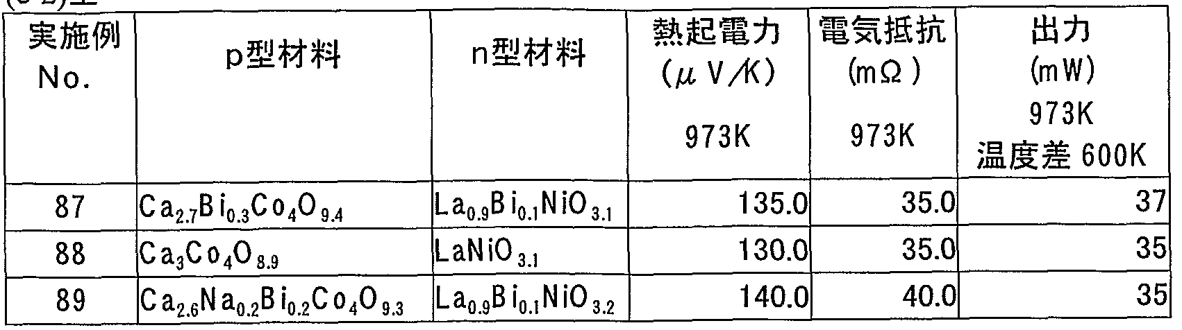
Claims


Priority Applications (1)
| Application Number | Priority Date | Filing Date | Title |
|---|---|---|---|
| JP2005512456A JP4595071B2 (ja) | 2003-07-30 | 2004-06-24 | 熱電変換素子、熱電変換モジュール及び熱電変換方法 |
Applications Claiming Priority (2)
| Application Number | Priority Date | Filing Date | Title |
|---|---|---|---|
| JP2003-282293 | 2003-07-30 | ||
| JP2003282293 | 2003-07-30 |
Publications (1)
| Publication Number | Publication Date |
|---|---|
| WO2005013383A1 true WO2005013383A1 (ja) | 2005-02-10 |
Family
ID=34113772
Family Applications (1)
| Application Number | Title | Priority Date | Filing Date |
|---|---|---|---|
| PCT/JP2004/009255 Ceased WO2005013383A1 (ja) | 2003-07-30 | 2004-06-24 | 熱電変換素子及び熱電変換モジュール |
Country Status (2)
| Country | Link |
|---|---|
| JP (1) | JP4595071B2 (ja) |
| WO (1) | WO2005013383A1 (ja) |
Cited By (1)
| Publication number | Priority date | Publication date | Assignee | Title |
|---|---|---|---|---|
| JP2009196821A (ja) * | 2008-02-19 | 2009-09-03 | Doshisha | ペロブスカイト系酸化物、当該酸化物の製造方法及び当該酸化物を用いた熱電素子 |
Citations (8)
| Publication number | Priority date | Publication date | Assignee | Title |
|---|---|---|---|---|
| JP2001019544A (ja) * | 1999-07-05 | 2001-01-23 | Agency Of Ind Science & Technol | 熱電変換材料及び複合酸化物焼結体の製造方法 |
| JP2001064021A (ja) * | 1999-08-26 | 2001-03-13 | Agency Of Ind Science & Technol | 高いゼーベック係数と高い電気伝導度を有する複合酸化物 |
| JP2001223393A (ja) * | 2000-02-10 | 2001-08-17 | Natl Inst Of Advanced Industrial Science & Technology Meti | 高いゼーベック係数と高い電気伝導度を有する複合酸化物 |
| JP2002076447A (ja) * | 2000-08-29 | 2002-03-15 | National Institute Of Advanced Industrial & Technology | 熱電材料の性能評価方法 |
| JP2002141562A (ja) * | 2000-10-31 | 2002-05-17 | National Institute Of Advanced Industrial & Technology | 優れた熱電変換性能を有する複合酸化物 |
| JP2002280619A (ja) * | 2001-03-19 | 2002-09-27 | Hokushin Ind Inc | 熱電変換材料及び熱電変換素子 |
| JP2003008086A (ja) * | 2001-06-22 | 2003-01-10 | Idemitsu Kosan Co Ltd | 複合酸化物及びそれを用いた熱電変換素子 |
| JP2003034583A (ja) * | 2001-07-18 | 2003-02-07 | Toyota Central Res & Dev Lab Inc | 板状粉末の製造方法及び結晶配向セラミックスの製造方法 |
-
2004
- 2004-06-24 JP JP2005512456A patent/JP4595071B2/ja not_active Expired - Fee Related
- 2004-06-24 WO PCT/JP2004/009255 patent/WO2005013383A1/ja not_active Ceased
Patent Citations (8)
| Publication number | Priority date | Publication date | Assignee | Title |
|---|---|---|---|---|
| JP2001019544A (ja) * | 1999-07-05 | 2001-01-23 | Agency Of Ind Science & Technol | 熱電変換材料及び複合酸化物焼結体の製造方法 |
| JP2001064021A (ja) * | 1999-08-26 | 2001-03-13 | Agency Of Ind Science & Technol | 高いゼーベック係数と高い電気伝導度を有する複合酸化物 |
| JP2001223393A (ja) * | 2000-02-10 | 2001-08-17 | Natl Inst Of Advanced Industrial Science & Technology Meti | 高いゼーベック係数と高い電気伝導度を有する複合酸化物 |
| JP2002076447A (ja) * | 2000-08-29 | 2002-03-15 | National Institute Of Advanced Industrial & Technology | 熱電材料の性能評価方法 |
| JP2002141562A (ja) * | 2000-10-31 | 2002-05-17 | National Institute Of Advanced Industrial & Technology | 優れた熱電変換性能を有する複合酸化物 |
| JP2002280619A (ja) * | 2001-03-19 | 2002-09-27 | Hokushin Ind Inc | 熱電変換材料及び熱電変換素子 |
| JP2003008086A (ja) * | 2001-06-22 | 2003-01-10 | Idemitsu Kosan Co Ltd | 複合酸化物及びそれを用いた熱電変換素子 |
| JP2003034583A (ja) * | 2001-07-18 | 2003-02-07 | Toyota Central Res & Dev Lab Inc | 板状粉末の製造方法及び結晶配向セラミックスの製造方法 |
Cited By (1)
| Publication number | Priority date | Publication date | Assignee | Title |
|---|---|---|---|---|
| JP2009196821A (ja) * | 2008-02-19 | 2009-09-03 | Doshisha | ペロブスカイト系酸化物、当該酸化物の製造方法及び当該酸化物を用いた熱電素子 |
Also Published As
| Publication number | Publication date |
|---|---|
| JP4595071B2 (ja) | 2010-12-08 |
| JPWO2005013383A1 (ja) | 2006-09-28 |
Similar Documents
| Publication | Publication Date | Title |
|---|---|---|
| JP4446064B2 (ja) | 熱電変換素子及び熱電変換モジュール | |
| JP4797148B2 (ja) | 熱電変換材料接続用導電性ペースト | |
| US7649139B2 (en) | Thermoelectric conversion element and thermoelectric conversion module | |
| US20120097206A1 (en) | Thermoelectric conversion module and thermoelectric conversion element | |
| US20140209140A1 (en) | Stacked thermoelectric conversion module | |
| JP3727945B2 (ja) | 熱電変換材料及びその製法 | |
| JP2001223393A (ja) | 高いゼーベック係数と高い電気伝導度を有する複合酸化物 | |
| JP7733911B2 (ja) | 熱電変換モジュール | |
| EP1492171B1 (en) | DOUBLE OXIDE WITH n TYPE THERMOELECTRIC CHARACTERISTICS | |
| JP4595123B2 (ja) | 熱電発電装置 | |
| JP4257419B2 (ja) | n型熱電変換特性を有する複合酸化物 | |
| JP4221496B2 (ja) | n型熱電特性を有する複合酸化物 | |
| JP4595071B2 (ja) | 熱電変換素子、熱電変換モジュール及び熱電変換方法 | |
| JP2002368294A (ja) | 高温用熱電変換モジュール | |
| JP2001019544A (ja) | 熱電変換材料及び複合酸化物焼結体の製造方法 | |
| WO2008038519A1 (fr) | Élément de conversion thermoélectrique, module de conversion thermoélectrique et procédé de production d'élément de conversion thermoélectrique | |
| JP2002118296A (ja) | 高い電気伝導率を有する高温用n型熱電変換素子及びそれを用いた熱電変換モジュール | |
| JP2003008086A (ja) | 複合酸化物及びそれを用いた熱電変換素子 | |
| JP2005268240A (ja) | 熱電モジュール | |
| JP2002141562A (ja) | 優れた熱電変換性能を有する複合酸化物 | |
| CA2979188A1 (en) | Thermoelectric conversion material, thermoelectric conversion element and thermoelectric conversion module | |
| Urata et al. | Mechanical properties of oxide materials | |
| JP2004107151A (ja) | 金属酸化物単結晶及び金属酸化物単結晶の製造方法 | |
| JP2004107126A (ja) | カリウム−マンガン含有複合酸化物 |
Legal Events
| Date | Code | Title | Description |
|---|---|---|---|
| AK | Designated states |
Kind code of ref document: A1 Designated state(s): AE AG AL AM AT AU AZ BA BB BG BR BW BY BZ CA CH CN CO CR CU CZ DE DK DM DZ EC EE EG ES FI GB GD GE GH GM HR HU ID IL IN IS JP KE KG KP KR KZ LC LK LR LS LT LU LV MA MD MG MK MN MW MX MZ NA NI NO NZ OM PG PH PL PT RO RU SC SD SE SG SK SL SY TJ TM TN TR TT TZ UA UG US UZ VC VN YU ZA ZM ZW |
|
| AL | Designated countries for regional patents |
Kind code of ref document: A1 Designated state(s): GM KE LS MW MZ NA SD SL SZ TZ UG ZM ZW AM AZ BY KG KZ MD RU TJ TM AT BE BG CH CY CZ DE DK EE ES FI FR GB GR HU IE IT LU MC NL PL PT RO SE SI SK TR BF BJ CF CG CI CM GA GN GQ GW ML MR NE SN TD TG |
|
| 121 | Ep: the epo has been informed by wipo that ep was designated in this application | ||
| WWE | Wipo information: entry into national phase |
Ref document number: 2005512456 Country of ref document: JP |
|
| 122 | Ep: pct application non-entry in european phase |