WO1999019521A1 - Method for producing a magnetic grain oriented steel sheet with low level loss by magnetic reversal and high polarisation - Google Patents
Method for producing a magnetic grain oriented steel sheet with low level loss by magnetic reversal and high polarisation Download PDFInfo
- Publication number
- WO1999019521A1 WO1999019521A1 PCT/EP1998/005732 EP9805732W WO9919521A1 WO 1999019521 A1 WO1999019521 A1 WO 1999019521A1 EP 9805732 W EP9805732 W EP 9805732W WO 9919521 A1 WO9919521 A1 WO 9919521A1
- Authority
- WO
- WIPO (PCT)
- Prior art keywords
- strip
- thickness
- hot
- rolled
- annealing
- Prior art date
Links
- 238000004519 manufacturing process Methods 0.000 title claims abstract description 22
- 229910000831 Steel Inorganic materials 0.000 title claims abstract description 20
- 239000010959 steel Substances 0.000 title claims abstract description 20
- 238000000034 method Methods 0.000 claims abstract description 62
- 238000000137 annealing Methods 0.000 claims abstract description 37
- 230000008569 process Effects 0.000 claims abstract description 24
- 238000005098 hot rolling Methods 0.000 claims abstract description 18
- 238000005096 rolling process Methods 0.000 claims abstract description 13
- 238000007711 solidification Methods 0.000 claims abstract description 12
- 230000008023 solidification Effects 0.000 claims abstract description 12
- 230000009467 reduction Effects 0.000 claims abstract description 6
- 238000010292 electrical insulation Methods 0.000 claims abstract 2
- 239000002245 particle Substances 0.000 claims description 25
- 238000001816 cooling Methods 0.000 claims description 14
- 239000000155 melt Substances 0.000 claims description 10
- 229910052717 sulfur Inorganic materials 0.000 claims description 9
- 229910052748 manganese Inorganic materials 0.000 claims description 7
- 229910052710 silicon Inorganic materials 0.000 claims description 7
- 229910052799 carbon Inorganic materials 0.000 claims description 5
- 229910052802 copper Inorganic materials 0.000 claims description 5
- XEEYBQQBJWHFJM-UHFFFAOYSA-N iron Substances [Fe] XEEYBQQBJWHFJM-UHFFFAOYSA-N 0.000 claims description 5
- 239000000203 mixture Substances 0.000 claims description 5
- 238000005121 nitriding Methods 0.000 claims description 5
- 229910052757 nitrogen Inorganic materials 0.000 claims description 5
- 229910052698 phosphorus Inorganic materials 0.000 claims description 4
- 229910052787 antimony Inorganic materials 0.000 claims description 3
- 229910052785 arsenic Inorganic materials 0.000 claims description 3
- 229910052797 bismuth Inorganic materials 0.000 claims description 3
- 239000012535 impurity Substances 0.000 claims description 3
- 229910052714 tellurium Inorganic materials 0.000 claims description 3
- 229910052718 tin Inorganic materials 0.000 claims description 3
- OAICVXFJPJFONN-UHFFFAOYSA-N Phosphorus Chemical compound [P] OAICVXFJPJFONN-UHFFFAOYSA-N 0.000 claims description 2
- 229910052742 iron Inorganic materials 0.000 claims description 2
- 239000011574 phosphorus Substances 0.000 claims description 2
- 239000011572 manganese Substances 0.000 claims 4
- 239000000161 steel melt Substances 0.000 claims 3
- OKTJSMMVPCPJKN-UHFFFAOYSA-N Carbon Chemical compound [C] OKTJSMMVPCPJKN-UHFFFAOYSA-N 0.000 claims 1
- PWHULOQIROXLJO-UHFFFAOYSA-N Manganese Chemical compound [Mn] PWHULOQIROXLJO-UHFFFAOYSA-N 0.000 claims 1
- NINIDFKCEFEMDL-UHFFFAOYSA-N Sulfur Chemical compound [S] NINIDFKCEFEMDL-UHFFFAOYSA-N 0.000 claims 1
- 238000002844 melting Methods 0.000 claims 1
- 230000008018 melting Effects 0.000 claims 1
- 239000011593 sulfur Substances 0.000 claims 1
- 238000005266 casting Methods 0.000 abstract description 16
- 238000010438 heat treatment Methods 0.000 abstract description 12
- 238000001953 recrystallisation Methods 0.000 abstract description 9
- 229910000976 Electrical steel Inorganic materials 0.000 abstract description 2
- 238000003723 Smelting Methods 0.000 abstract 1
- 238000005262 decarbonization Methods 0.000 abstract 1
- 239000003112 inhibitor Substances 0.000 description 35
- 238000005097 cold rolling Methods 0.000 description 16
- 238000009749 continuous casting Methods 0.000 description 8
- 239000000463 material Substances 0.000 description 8
- 230000008901 benefit Effects 0.000 description 7
- 230000015572 biosynthetic process Effects 0.000 description 7
- 230000000694 effects Effects 0.000 description 7
- 238000001556 precipitation Methods 0.000 description 6
- 239000000126 substance Substances 0.000 description 6
- 150000003568 thioethers Chemical class 0.000 description 6
- 238000011282 treatment Methods 0.000 description 6
- 238000012545 processing Methods 0.000 description 5
- IJGRMHOSHXDMSA-UHFFFAOYSA-N Atomic nitrogen Chemical compound N#N IJGRMHOSHXDMSA-UHFFFAOYSA-N 0.000 description 4
- 239000003966 growth inhibitor Substances 0.000 description 4
- 239000011159 matrix material Substances 0.000 description 4
- 150000004767 nitrides Chemical class 0.000 description 4
- 229910001224 Grain-oriented electrical steel Inorganic materials 0.000 description 3
- 238000007792 addition Methods 0.000 description 3
- 229910001566 austenite Inorganic materials 0.000 description 3
- 230000002401 inhibitory effect Effects 0.000 description 3
- 230000005764 inhibitory process Effects 0.000 description 3
- 239000002184 metal Substances 0.000 description 3
- 229910052751 metal Inorganic materials 0.000 description 3
- 230000010287 polarization Effects 0.000 description 3
- UCKMPCXJQFINFW-UHFFFAOYSA-N Sulphide Chemical compound [S-2] UCKMPCXJQFINFW-UHFFFAOYSA-N 0.000 description 2
- 239000011362 coarse particle Substances 0.000 description 2
- 230000006378 damage Effects 0.000 description 2
- 238000005261 decarburization Methods 0.000 description 2
- 238000011161 development Methods 0.000 description 2
- 238000009826 distribution Methods 0.000 description 2
- 238000005516 engineering process Methods 0.000 description 2
- 230000002349 favourable effect Effects 0.000 description 2
- 230000009036 growth inhibition Effects 0.000 description 2
- 238000003303 reheating Methods 0.000 description 2
- 238000000926 separation method Methods 0.000 description 2
- 238000009864 tensile test Methods 0.000 description 2
- -1 Cu 2 S Chemical class 0.000 description 1
- 229910001209 Low-carbon steel Inorganic materials 0.000 description 1
- 229910016964 MnSb Inorganic materials 0.000 description 1
- 230000006978 adaptation Effects 0.000 description 1
- 229910045601 alloy Inorganic materials 0.000 description 1
- 239000000956 alloy Substances 0.000 description 1
- 229910052782 aluminium Inorganic materials 0.000 description 1
- 238000006243 chemical reaction Methods 0.000 description 1
- 238000010960 commercial process Methods 0.000 description 1
- 230000002860 competitive effect Effects 0.000 description 1
- 238000007796 conventional method Methods 0.000 description 1
- 238000005336 cracking Methods 0.000 description 1
- 238000002425 crystallisation Methods 0.000 description 1
- 230000008025 crystallization Effects 0.000 description 1
- 230000008030 elimination Effects 0.000 description 1
- 238000003379 elimination reaction Methods 0.000 description 1
- 230000002708 enhancing effect Effects 0.000 description 1
- 230000029142 excretion Effects 0.000 description 1
- 238000002474 experimental method Methods 0.000 description 1
- 230000004907 flux Effects 0.000 description 1
- 239000007789 gas Substances 0.000 description 1
- 238000000265 homogenisation Methods 0.000 description 1
- 238000011835 investigation Methods 0.000 description 1
- 238000011031 large-scale manufacturing process Methods 0.000 description 1
- 239000007788 liquid Substances 0.000 description 1
- 230000005415 magnetization Effects 0.000 description 1
- 230000007246 mechanism Effects 0.000 description 1
- QJGQUHMNIGDVPM-UHFFFAOYSA-N nitrogen group Chemical group [N] QJGQUHMNIGDVPM-UHFFFAOYSA-N 0.000 description 1
- 238000010791 quenching Methods 0.000 description 1
- 230000000171 quenching effect Effects 0.000 description 1
- 150000003346 selenoethers Chemical class 0.000 description 1
- 230000035945 sensitivity Effects 0.000 description 1
- 238000004904 shortening Methods 0.000 description 1
- 239000007921 spray Substances 0.000 description 1
- 230000000087 stabilizing effect Effects 0.000 description 1
- 239000010935 stainless steel Substances 0.000 description 1
- 229910001220 stainless steel Inorganic materials 0.000 description 1
- 238000012360 testing method Methods 0.000 description 1
- 230000009466 transformation Effects 0.000 description 1
- 238000010792 warming Methods 0.000 description 1
- XLYOFNOQVPJJNP-UHFFFAOYSA-N water Substances O XLYOFNOQVPJJNP-UHFFFAOYSA-N 0.000 description 1
Classifications
-
- C—CHEMISTRY; METALLURGY
- C21—METALLURGY OF IRON
- C21D—MODIFYING THE PHYSICAL STRUCTURE OF FERROUS METALS; GENERAL DEVICES FOR HEAT TREATMENT OF FERROUS OR NON-FERROUS METALS OR ALLOYS; MAKING METAL MALLEABLE, e.g. BY DECARBURISATION OR TEMPERING
- C21D8/00—Modifying the physical properties by deformation combined with, or followed by, heat treatment
- C21D8/12—Modifying the physical properties by deformation combined with, or followed by, heat treatment during manufacturing of articles with special electromagnetic properties
- C21D8/1205—Modifying the physical properties by deformation combined with, or followed by, heat treatment during manufacturing of articles with special electromagnetic properties involving a particular fabrication or treatment of ingot or slab
-
- C—CHEMISTRY; METALLURGY
- C21—METALLURGY OF IRON
- C21D—MODIFYING THE PHYSICAL STRUCTURE OF FERROUS METALS; GENERAL DEVICES FOR HEAT TREATMENT OF FERROUS OR NON-FERROUS METALS OR ALLOYS; MAKING METAL MALLEABLE, e.g. BY DECARBURISATION OR TEMPERING
- C21D1/00—General methods or devices for heat treatment, e.g. annealing, hardening, quenching or tempering
- C21D1/26—Methods of annealing
- C21D1/30—Stress-relieving
-
- C—CHEMISTRY; METALLURGY
- C21—METALLURGY OF IRON
- C21D—MODIFYING THE PHYSICAL STRUCTURE OF FERROUS METALS; GENERAL DEVICES FOR HEAT TREATMENT OF FERROUS OR NON-FERROUS METALS OR ALLOYS; MAKING METAL MALLEABLE, e.g. BY DECARBURISATION OR TEMPERING
- C21D6/00—Heat treatment of ferrous alloys
- C21D6/008—Heat treatment of ferrous alloys containing Si
-
- C—CHEMISTRY; METALLURGY
- C21—METALLURGY OF IRON
- C21D—MODIFYING THE PHYSICAL STRUCTURE OF FERROUS METALS; GENERAL DEVICES FOR HEAT TREATMENT OF FERROUS OR NON-FERROUS METALS OR ALLOYS; MAKING METAL MALLEABLE, e.g. BY DECARBURISATION OR TEMPERING
- C21D8/00—Modifying the physical properties by deformation combined with, or followed by, heat treatment
- C21D8/12—Modifying the physical properties by deformation combined with, or followed by, heat treatment during manufacturing of articles with special electromagnetic properties
- C21D8/1216—Modifying the physical properties by deformation combined with, or followed by, heat treatment during manufacturing of articles with special electromagnetic properties the working step(s) being of interest
- C21D8/1222—Hot rolling
-
- C—CHEMISTRY; METALLURGY
- C21—METALLURGY OF IRON
- C21D—MODIFYING THE PHYSICAL STRUCTURE OF FERROUS METALS; GENERAL DEVICES FOR HEAT TREATMENT OF FERROUS OR NON-FERROUS METALS OR ALLOYS; MAKING METAL MALLEABLE, e.g. BY DECARBURISATION OR TEMPERING
- C21D8/00—Modifying the physical properties by deformation combined with, or followed by, heat treatment
- C21D8/12—Modifying the physical properties by deformation combined with, or followed by, heat treatment during manufacturing of articles with special electromagnetic properties
- C21D8/1244—Modifying the physical properties by deformation combined with, or followed by, heat treatment during manufacturing of articles with special electromagnetic properties the heat treatment(s) being of interest
- C21D8/1255—Modifying the physical properties by deformation combined with, or followed by, heat treatment during manufacturing of articles with special electromagnetic properties the heat treatment(s) being of interest with diffusion of elements, e.g. decarburising, nitriding
-
- C—CHEMISTRY; METALLURGY
- C21—METALLURGY OF IRON
- C21D—MODIFYING THE PHYSICAL STRUCTURE OF FERROUS METALS; GENERAL DEVICES FOR HEAT TREATMENT OF FERROUS OR NON-FERROUS METALS OR ALLOYS; MAKING METAL MALLEABLE, e.g. BY DECARBURISATION OR TEMPERING
- C21D8/00—Modifying the physical properties by deformation combined with, or followed by, heat treatment
- C21D8/12—Modifying the physical properties by deformation combined with, or followed by, heat treatment during manufacturing of articles with special electromagnetic properties
- C21D8/1277—Modifying the physical properties by deformation combined with, or followed by, heat treatment during manufacturing of articles with special electromagnetic properties involving a particular surface treatment
- C21D8/1283—Application of a separating or insulating coating
-
- C—CHEMISTRY; METALLURGY
- C22—METALLURGY; FERROUS OR NON-FERROUS ALLOYS; TREATMENT OF ALLOYS OR NON-FERROUS METALS
- C22C—ALLOYS
- C22C38/00—Ferrous alloys, e.g. steel alloys
- C22C38/02—Ferrous alloys, e.g. steel alloys containing silicon
-
- C—CHEMISTRY; METALLURGY
- C21—METALLURGY OF IRON
- C21D—MODIFYING THE PHYSICAL STRUCTURE OF FERROUS METALS; GENERAL DEVICES FOR HEAT TREATMENT OF FERROUS OR NON-FERROUS METALS OR ALLOYS; MAKING METAL MALLEABLE, e.g. BY DECARBURISATION OR TEMPERING
- C21D8/00—Modifying the physical properties by deformation combined with, or followed by, heat treatment
- C21D8/12—Modifying the physical properties by deformation combined with, or followed by, heat treatment during manufacturing of articles with special electromagnetic properties
- C21D8/1205—Modifying the physical properties by deformation combined with, or followed by, heat treatment during manufacturing of articles with special electromagnetic properties involving a particular fabrication or treatment of ingot or slab
- C21D8/1211—Rapid solidification; Thin strip casting
-
- C—CHEMISTRY; METALLURGY
- C21—METALLURGY OF IRON
- C21D—MODIFYING THE PHYSICAL STRUCTURE OF FERROUS METALS; GENERAL DEVICES FOR HEAT TREATMENT OF FERROUS OR NON-FERROUS METALS OR ALLOYS; MAKING METAL MALLEABLE, e.g. BY DECARBURISATION OR TEMPERING
- C21D8/00—Modifying the physical properties by deformation combined with, or followed by, heat treatment
- C21D8/12—Modifying the physical properties by deformation combined with, or followed by, heat treatment during manufacturing of articles with special electromagnetic properties
- C21D8/1216—Modifying the physical properties by deformation combined with, or followed by, heat treatment during manufacturing of articles with special electromagnetic properties the working step(s) being of interest
- C21D8/1233—Cold rolling
-
- C—CHEMISTRY; METALLURGY
- C21—METALLURGY OF IRON
- C21D—MODIFYING THE PHYSICAL STRUCTURE OF FERROUS METALS; GENERAL DEVICES FOR HEAT TREATMENT OF FERROUS OR NON-FERROUS METALS OR ALLOYS; MAKING METAL MALLEABLE, e.g. BY DECARBURISATION OR TEMPERING
- C21D8/00—Modifying the physical properties by deformation combined with, or followed by, heat treatment
- C21D8/12—Modifying the physical properties by deformation combined with, or followed by, heat treatment during manufacturing of articles with special electromagnetic properties
- C21D8/1244—Modifying the physical properties by deformation combined with, or followed by, heat treatment during manufacturing of articles with special electromagnetic properties the heat treatment(s) being of interest
- C21D8/1261—Modifying the physical properties by deformation combined with, or followed by, heat treatment during manufacturing of articles with special electromagnetic properties the heat treatment(s) being of interest following hot rolling
-
- C—CHEMISTRY; METALLURGY
- C21—METALLURGY OF IRON
- C21D—MODIFYING THE PHYSICAL STRUCTURE OF FERROUS METALS; GENERAL DEVICES FOR HEAT TREATMENT OF FERROUS OR NON-FERROUS METALS OR ALLOYS; MAKING METAL MALLEABLE, e.g. BY DECARBURISATION OR TEMPERING
- C21D8/00—Modifying the physical properties by deformation combined with, or followed by, heat treatment
- C21D8/12—Modifying the physical properties by deformation combined with, or followed by, heat treatment during manufacturing of articles with special electromagnetic properties
- C21D8/1244—Modifying the physical properties by deformation combined with, or followed by, heat treatment during manufacturing of articles with special electromagnetic properties the heat treatment(s) being of interest
- C21D8/1272—Final recrystallisation annealing
-
- Y—GENERAL TAGGING OF NEW TECHNOLOGICAL DEVELOPMENTS; GENERAL TAGGING OF CROSS-SECTIONAL TECHNOLOGIES SPANNING OVER SEVERAL SECTIONS OF THE IPC; TECHNICAL SUBJECTS COVERED BY FORMER USPC CROSS-REFERENCE ART COLLECTIONS [XRACs] AND DIGESTS
- Y02—TECHNOLOGIES OR APPLICATIONS FOR MITIGATION OR ADAPTATION AGAINST CLIMATE CHANGE
- Y02P—CLIMATE CHANGE MITIGATION TECHNOLOGIES IN THE PRODUCTION OR PROCESSING OF GOODS
- Y02P10/00—Technologies related to metal processing
- Y02P10/20—Recycling
Definitions
- the invention relates to a method for producing grain-oriented electrical sheet with low magnetic loss and high polarization.
- Steels with 2.5 to 4.0% Si, 0.010 to 0.100% C, up to 0.150% Mn, up to 0.065% AI and up to 0.0150% N, as well as, are used to produce grain-oriented electrical sheets (K0 sheet) each optionally 0.010 to 0.3% Cu, up to 0.060% S, up to 0.100% P, up to 0.2% As, Sn, Sb, Te, and Bi, the rest iron and unavoidable impurities melted and poured off.
- the solidified strands with thicknesses of 25 to 100 mm are cut into thin slabs without cooling below 700 ° C and homogeneously heated to a temperature of up to 1170 ° C in a compensating furnace in line, the residence time being up to a maximum of 60 min .
- These homogeneously heated thin slabs are then continuously rolled and coiled into hot strip with a thickness of 0.5 to 3.0 mm in a multi-stand hot rolling mill.
- the hot strip is optionally annealed.
- the hot strip treated in this way is cold rolled in one or more passes to a finished strip thickness of 0.15 to 0.50 mm.
- the cold strip is annealed to recrystallize and decarburize.
- it is isolated in a final annealing and relieved of internal residual stresses.
- Grain-oriented electrical sheets are used in particular in power transformers to guide the magnetic flux. Therefore, the lowest possible magnetization losses and the highest possible polarization values are necessary. For this purpose, a very sharp cast texture is created in grain-oriented electrical sheets, which means that very good magnetic properties are achieved along the rolling direction as the preferred magnetic direction.
- the high slab thickness of the conventional continuous casting process proves to be Particularly disadvantageous because it causes high and inhomogeneous temperature gradients when the slabs are reheated, which lead to high internal stresses.
- slabs for KO sheet metal usually have to be stored in a heated holding furnace at temperatures of 100 ... 500 ° C, for example.
- the disadvantages of this way of working are the increased energy expenditure and the complication and cost of the processing process.
- the slabs produced using the conventional continuous casting process are then used in a pusher furnace, a walking beam furnace or in an aggregate with the same effect and heated to sufficiently high temperatures so that good hot formability is achieved.
- Hot rolling then usually takes place in two steps: The slabs, which are 100 to 300 mm thick, are first cut to a thickness of approx. Pre-rolled 30 to 60 mm. This roughing is often done in reversing stands. The pre-slabs are then rolled out continuously in a multi-frame finishing line to form hot strip in thicknesses of 2.0 to 6.0 mm.
- KO-sheet which is manufactured according to the conventional method, has the special feature that heating the slabs to temperatures up to 1400 ° C is absolutely necessary to dissolve foreign phase particles in the slab so that they are finely dispersed in the subsequent hot rolling can be
- these particles are mainly Mn sulfides or Mn selenides
- Another method uses Al nitrides (US 3 159 511; US 3 287 183).
- MnSe and MnSb (DE 23 51 141 A) are generated.
- other nitrides such as VN, (Al, Si) N, ... (DE 19 20 666 A, EP 0 219 611) and sulfides such as Cu 2 S, TiS, CrS, ... (EP 0 619 376 AI, DE 23 48 249 A).
- the general task of these particles is to block the movement of grain boundaries in the subsequent manufacturing steps until secondary recrystallization and thus to inhibit normal grain growth during various annealing treatments.
- the precipitations in conventional continuous casting are usually so coarse that there are practically no particles below a size of 100 nm.
- the coarse particles must therefore be dissolved during the slab preheating.
- annealing temperatures of up to approx. 1400 ° C are required.
- the particles are separated out again in the desired manner.
- the slabs can be heated to the high temperature required to dissolve the particles acting as grain growth inhibitors either directly in one oven or in two ovens in succession. in the in the latter case, the slabs are heated, for example, to 1250 ° C. in the first furnace, then to temperatures of up to 1400 ° C. Although it complicates the process and makes it more expensive, it has proven advantageous for the magnetic properties of the finished product to carry out a first hot forming of the slab ("Prerollmg") between these two stages in order to homogenize and refine its structure (EP 0 193 373 Bl ).
- Prerollmg a first hot forming of the slab
- the high slab preheating temperature required for the formation of the inhibitor phase complicates and increases the cost of the production process for the hot strip for KO sheet metal because investments are required for special, complex high-temperature furnaces, because the liquid scale that occurs on silicon steel slabs above 1350 ° C damages the furnace hearth and this is associated with injuries on the underside of the slab, which cause output losses.
- the optional intermediate prerolling also makes production more expensive and displaces capacity that could be used to manufacture other flat steel products.
- MnS or MnSe particles have only a limited effect on grain growth inhibition. It must only be countered by a correspondingly adjusted driving force for grain enlargement, so that the desired Goss selection process can take place at the right moment during the secondary crystallization. This means that the degree of deformation in the last cold rolling stage to the final thickness must not be too great.
- the most favorable reduction in thickness m of this cold rolling stage of the Si steel inhibited with MnS or MnSe is 40 ... 60%. Since the hot strip thickness is difficult with the conventional hot rolling technology without quality and Output losses must be reduced to below 2.0 mm, the optimum degree of deformation during cold rolling to final thickness must be achieved by rolling in several stages, between which there is a recrystallizing intermediate annealing.
- the KO sheet that can be produced in this complex way has misalignment angles of up to approx. 10 ° with respect to the exact cast position.
- Hi-B process US Pat. No. 3,159,511, US Pat. No. 3,287,183
- AIN particles in addition to MnS, AIN particles as a further inhibitor phase
- high slab heating temperatures e.g. 1400 ° C are required.
- the A1N is not yet in a suitably finely dispersed particle distribution, but only achieves this by precipitation annealing of the hot strip with subsequent quenching.
- the internal nature of the hot strip with regard to its chemical composition, the formation of its grain structure and the morphology of its second phase components must therefore be such that it has the ability to separate A1N inhibitor phase particles.
- the grain growth inhibition is increased overall by the AIN particles.
- the method according to EP 0 219 611 works entirely without sulfidic inhibitors.
- the S content can therefore be reduced to trace levels.
- the slab preheating temperature is particularly low with values below 1200 ° C. It is not possible to form a sufficiently effective inhibitor phase that is already available in the hot strip.
- Such a hot strip produced by the conventional continuous casting technique also does not have the ability to form the corresponding inhibitor phase by means of a precipitation annealing.
- the inhibitor AIN is therefore formed by nitriding the strip cold-rolled to the finished strip thickness before the high-temperature annealing.
- Various methods are specified in EP 0 321 695 B1 with which such a nitriding process can be carried out.
- Another method uses Cu sulfides as inhibitors. These have a significantly lower solubility temperature and faster solubility kinetics than AIN and MnS. The inhibitor formation does not yet take place during hot rolling in the right way, however, the hot strip produced by this method has the ability to excrete Cu sulfide inhibitor particles. These are generated during a precipitation annealing treatment of the hot rolled strip.
- One of the main problems is to achieve suitable microstructure and precipitation structures during solidification in the small thicknesses and in the subsequent cooling, which, after further cold forming and heat treatment, give rise to a sharp cast texture in the finished product, so that its magnetic properties are competitive with the grain-oriented electrical sheet produced using conventional continuous casting technology (EP 0 390 160 Bl, EP 0 540 405 Bl).
- the invention has for its object to overcome disadvantages of conventional production methods and to use the economic advantages of thin slab casting also for grain-oriented electrical sheet.
- the problem is solved according to the method of claim 1 by optimizing the manufacturing steps of casting, solidification and hot rolling. This involves the selection of various mechanisms for the formation of the inhibitor phase and the adaptation of the subsequent processing steps.
- a melt is continuously poured into a vertical mold, at the end of which the melt solidifies and the strand formed in this way is transferred to the horizontal via an arc and is thereby cooled.
- This strand has a thickness of only 25 to 100 mm, preferably 40 ... 70 mm. It is not completely cooled, but its temperature does not drop below 700 ° C.
- This hot strand is cut into thin slabs, which are passed directly through a line-leveling furnace in which they remain for a maximum of 60 minutes, preferably for up to 30 minutes. During this passage through the equalization furnace, the thin slabs are heated homogeneously and reach a relatively low temperature of a maximum of 1170 ° C.
- the thin slabs are passed through a multi-stand hot rolling mill in line, where they are continuously hot-rolled to the hot strip thickness of 0.5 to 3.0 mm.
- the hot strip thickness should be selected so that the subsequent cold rolling process is only carried out in one step.
- the degree of forming of this cold rolling depends on the respective inhibitor effect which can be set in different ways.
- the advantage of the method of operation according to the invention is, on the one hand, that a large part of the heat from the casting process is used, which eliminates the need to keep the slabs warm in heated furnaces, which is known from the prior art for KO sheet metal, and to reheat the slabs to high temperatures in the pusher furnace or walking beam furnace.
- the annealing treatment in its place in a compensating furnace has the task of setting a defined homogeneous temperature over the entire thickness of the thin slab. Due to their small thickness, thin slabs require much less time than conventional slabs with thicknesses of 100 ... 300 mm. In this way, considerable amounts of energy and reheating time are saved compared to the prior art.
- the prerollmg inserted into the slab warming process for structural homogenization and the pre-rolling at the beginning of the hot strip rolling process are eliminated. This results in a considerable reduction in the production route, direct cost savings and increases in capacity on the hot strip mill for the manufacture of other flat steel products.
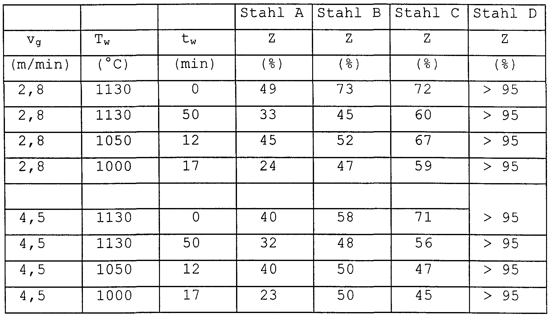
- the hot rolling parameters must be selected so that the material remains sufficiently ductile. Experiments have shown that in the case of pre-material for grain-oriented electrical sheet, the ductility is greatest when the strand is cooled to about 800 ° C.
- Such a material can be optimally rolled when the first forming pass is carried out at temperatures below 1150 ° C and with a degree of forming of at least 20% and the rolling stock from an intermediate thickness of 40 to 8 mm by means of high-pressure interframe cooling devices within a maximum of two consecutive forming passes are brought to rolling temperatures below 1000 ° C. This prevents the rolled stock from being deformed in the temperature range critical for ductility by 1000 ° C.
- Table 1 shows the chemical composition of four steels which were tested for their suitability for hot rolling in the manner according to the invention.
- Fracture constriction is the essential parameter for ductility. From the data it can be seen that, depending on their chemical composition, the steels react with different sensitivity to the respective stress cycles. Steel D shows the lowest, steel A the highest losses in terms of breakage or ductility.
- the Mn content must be in the range from 0.050 to 0.100% and the S content in the range from 0.015 to 0.035%. Inadequate proportions of these elements prevent one sufficient amount of substance for the inhibitors. Excessively high fractions result in the removal of coarse particles. Therefore, the proportions of Mn and S should be in the range of 0.05 to 0.10% Mn and 0.015 to 0.035% S.
- the hot strip thickness can be set so low that further processing can take place with only one cold rolling stage.
- the degree of cold rolling should be in the range of 45 to 75%.
- a considerable advantage of the process is that it does not have to be cold rolled in several stages. It may There are logistical advantages in producing only hot strip of a fixed thickness and adapting the degree of cold forming depending on the application by means of multi-stage cold rolling.
- the method specified in claim 3 therefore also permits multi-stage cold rolling with intermediate annealing.
- Claim 4 calls an annealing to be advantageously carried out at 800 to 1100 ° C.
- the reel temperature can be set to less than or equal to 900 ° C. This annealing improves the grain structure in the hot strip, in particular the surface areas near the surface, which are important for the further processing steps, are enlarged. Additional inhibitors are not formed in the aforementioned heat treatments.
- Claim 5 specifies a method in which the hot strip does not yet contain the grain growth inhibitors in the final form. Rather, it is such that it is Has the ability to form corresponding inhibitor particles during an annealing. Cu sulfide and Al nitride are particularly suitable as inhibitors for this.
- This procedure has the advantage that the hot strip production (casting, solidification, compensation annealing, hot rolling) does not also have to be optimized for an optimal formation of the inhibitor phase, which opens up additional degrees of freedom.
- the cooling rate of the cast strand must be chosen so high that the grain structure of the thin slab does not become too coarse. For this purpose, it also makes sense to choose the shortest possible residence time in the compensating furnace.
- the inhibitor particles are separated during the hot strip precipitation annealing at 950 to 1150 ° C, which is ended with a particularly rapid cooling.
- the inhibitor phase-forming elements are brought into solution, in order to then separate out the inhibitor phase in a finely dispersed manner during the very rapid cooling, preferably with spray water, at> 20 K / s.
- This method of working is possible because Cu sulfides have a significantly lower solubility temperature and faster reaction kinetics than, for example, MnS.
- MnS solubility temperature and faster reaction kinetics than, for example, MnS.
- the C content must be so high that austenite transformation can take place at least to a small extent. However, if it is chosen above 0.10%, problems with decarburization can occur.
- the degree of cold deformation can be set at 70 ... 90%, significantly higher than in the method in claim 3.
- the higher energy thereby introduced and thus the driving force for secondary grain growth stands in the method specified in claim 5 against a correspondingly higher inhibitory effect. Similar to the HiB process results from a better texture selection and thus a sharper cast layer in the finished strip and finally better magnetic properties compared to a material produced according to claim 3.
- the method according to claim 6 characterizes a process in which only AIN is used as an inhibitor. Its advantage lies in the practically complete avoidance of Cu and S in the melt, which facilitates hot rolling and reduces the brittleness of the material. Similar to the method according to claim 3, the high cooling rate of the cast strand partially prevents the inhibitor-forming elements (AI and N) present in the melt from being eliminated. Possibly excreted particles are only small in size. The complete separation takes place as in claim 3 with the homogeneous heating in the equalizing furnace.
- this hot strip can have the ability to separate further AIN particles which can act as inhibitors if it is ensured by a sufficiently high C content that sufficient austenite is produced when the hot strip is annealed.
- the total inhibitor effect set in such a material thus depends on how quickly the strand is cooled, how many effective inhibitors could spontaneously form at the beginning. Furthermore, it depends on how many inhibitors were additionally generated when the hot strip was excreted; this depends very much on the C content. Depending on how strong this overall inhibitory effect is, different degrees of cold deformation must be set.
- additional method features are claimed which can facilitate the application of the method outlined in claims 1 to 6:
- the measure claimed in claim 8 restricting the superheating temperature during casting to a maximum of 25 K above the liquidus temperature basically has the same aim as the measure in claim 7, namely to make the structure of the solidification structure as homogeneous and fine-grained as possible. If the melt is poured at a temperature that is only slightly above the liquidus temperature of the corresponding alloy, a largely globulitic solidification structure is created and the dendritic growth is restricted.
- it is always important to set a solidification structure that is as finely structured as possible so that on the one hand the texture and the structure development can run as homogeneously as possible in the volume of the slab or thin slab.
- a structure that is as finely structured as possible favors the desired finely dispersed elimination of the inhibitor phase.
- Claim 9 shows a possibility for enhancing the overall inhibition effect by forming nitride treatment of the strip cold-rolled to finished strip thickness m of the matrix additional AIN particles, of which a sufficiently large proportion is below its size 100 nm.
- the additional AIN particles formed in this way must in any case arise in the matrix before the start of secondary recrystallization, so that they can still have an advantageous effect on the secondary recrystallization.
- This nitriding treatment can take place in the heating phase at the beginning of the high-temperature annealing and can be brought about, for example, by a high nitrogen-containing annealing atmosphere.
- annealing separator which predominantly contains MgO
- these additions consisting of substances which give off nitrogen at the beginning of the high-temperature annealing, which can then diffuse into the matrix.
- a very effective method for nitriding is to insert a corresponding process step at the end of the decarburization annealing, whereby nitrogen can diffuse out of the annealing gas into the strip.
- Elements which segregate at the grain boundaries such as As, Sn, Sb, Te and Bi in an amount of up to 0.2% each, have a favorable influence on stabilizing the secondary recrystallization and on sharpening the Goss texture.
Abstract
Description


Claims
Priority Applications (10)
| Application Number | Priority Date | Filing Date | Title |
|---|---|---|---|
| BR9813255-5A BR9813255A (en) | 1997-10-15 | 1998-09-09 | Process for the production of electrical quality sheets with oriented granulation with low loss of remagnetization and high polarization |
| AU92670/98A AU730723B2 (en) | 1997-10-15 | 1998-09-09 | Process for the production of grain-oriented electric quality sheet with low remagnetisation loss and high polarisation |
| HU0004822A HUP0004822A3 (en) | 1997-10-15 | 1998-09-09 | Method for producing a magnetic grain oriented steel sheet with low level loss by magnetic reversal and high polarisation |
| JP2000516071A JP5188658B2 (en) | 1997-10-15 | 1998-09-09 | Method for producing grain-oriented silicon steel sheet having low hysteresis loss and high polarity |
| US09/529,339 US6524400B1 (en) | 1997-10-15 | 1998-09-09 | Process for the production of grain-oriented electric quality sheet with low remagnetization loss and high polarization |
| DE59804081T DE59804081D1 (en) | 1997-10-15 | 1998-09-09 | METHOD FOR THE PRODUCTION OF CORNORIENTED ELECTRIC SHEET WITH LOW RE-MAGNETIZATION LOSS AND HIGH POLARIZATION |
| KR1020007004009A KR100566597B1 (en) | 1997-10-15 | 1998-09-09 | Method for producing a magnetic grain oriented steel sheet with low level loss by magnetic reversal and high polarisation |
| EP98945320A EP1025268B1 (en) | 1997-10-15 | 1998-09-09 | Method for producing a magnetic grain oriented steel sheet with low level loss by magnetic reversal and high polarisation |
| CA002306208A CA2306208C (en) | 1997-10-15 | 1998-09-09 | Method for producing a magnetic grain oriented steel sheet with low level loss by magnetic reversal and high polarisation |
| PL98339842A PL188187B1 (en) | 1997-10-15 | 1998-09-09 | Method of making oriented-crystallite electromagnetic steel sheats of low overmagnetisation loss and high dipole density |
Applications Claiming Priority (2)
| Application Number | Priority Date | Filing Date | Title |
|---|---|---|---|
| DE19745445.3 | 1997-10-15 | ||
| DE19745445A DE19745445C1 (en) | 1997-10-15 | 1997-10-15 | Process for the production of grain-oriented electrical sheet with low magnetic loss and high polarization |
Publications (1)
| Publication Number | Publication Date |
|---|---|
| WO1999019521A1 true WO1999019521A1 (en) | 1999-04-22 |
Family
ID=7845557
Family Applications (1)
| Application Number | Title | Priority Date | Filing Date |
|---|---|---|---|
| PCT/EP1998/005732 WO1999019521A1 (en) | 1997-10-15 | 1998-09-09 | Method for producing a magnetic grain oriented steel sheet with low level loss by magnetic reversal and high polarisation |
Country Status (15)
| Country | Link |
|---|---|
| US (1) | US6524400B1 (en) |
| EP (1) | EP1025268B1 (en) |
| JP (1) | JP5188658B2 (en) |
| KR (1) | KR100566597B1 (en) |
| AU (1) | AU730723B2 (en) |
| BR (1) | BR9813255A (en) |
| CA (1) | CA2306208C (en) |
| CZ (1) | CZ291078B6 (en) |
| DE (2) | DE19745445C1 (en) |
| HU (1) | HUP0004822A3 (en) |
| MY (1) | MY122168A (en) |
| PL (1) | PL188187B1 (en) |
| TW (1) | TW397869B (en) |
| WO (1) | WO1999019521A1 (en) |
| ZA (1) | ZA988932B (en) |
Cited By (5)
| Publication number | Priority date | Publication date | Assignee | Title |
|---|---|---|---|---|
| WO2007014868A1 (en) * | 2005-08-03 | 2007-02-08 | Thyssenkrupp Steel Ag | Method for producing a grain-oriented electrical steel strip |
| WO2007014867A1 (en) * | 2005-08-03 | 2007-02-08 | Thyssenkrupp Steel Ag | Method for producing a grain-oriented electrical steel strip |
| EP3715480A1 (en) | 2019-03-26 | 2020-09-30 | Thyssenkrupp Electrical Steel Gmbh | Iron-silicon material suitable for medium frequency applications |
| EP3715479A1 (en) | 2019-03-26 | 2020-09-30 | Thyssenkrupp Electrical Steel Gmbh | Lean method for secondary recrystallization of grain oriented electrical steel in a continuous processing line |
| EP4273280A1 (en) | 2022-05-04 | 2023-11-08 | Thyssenkrupp Electrical Steel Gmbh | Method for producing a grain-oriented electrical steel strip and grain-oriented electrical steel strip |
Families Citing this family (22)
| Publication number | Priority date | Publication date | Assignee | Title |
|---|---|---|---|---|
| ITRM20070218A1 (en) * | 2007-04-18 | 2008-10-19 | Ct Sviluppo Materiali Spa | PROCEDURE FOR THE PRODUCTION OF MAGNETIC SHEET WITH ORIENTED GRAIN |
| DE102008029581A1 (en) | 2007-07-21 | 2009-01-22 | Sms Demag Ag | Method and apparatus for making strips of silicon or multi-phase steel |
| KR101346537B1 (en) * | 2009-04-06 | 2013-12-31 | 신닛테츠스미킨 카부시키카이샤 | Method for treating steel for directional electromagnetic steel plate and method for producing directional electromagnetic steel plate |
| RU2407809C1 (en) * | 2009-08-03 | 2010-12-27 | Открытое акционерное общество "Новолипецкий металлургический комбинат" | Procedure for production of anisotropic electro-technical steel with high magnetic properties |
| RU2407808C1 (en) * | 2009-08-03 | 2010-12-27 | Открытое акционерное общество "Новолипецкий металлургический комбинат" | Procedure for production of anisotropic electro-technical steel with low specific losses for re-magnetisation |
| US20120222777A1 (en) * | 2009-11-25 | 2012-09-06 | Tata Steel Ijmuiden B.V. | Process to manufacture grain-oriented electrical steel strip and grain-oriented electrical steel produced thereby |
| WO2011114178A1 (en) * | 2010-03-19 | 2011-09-22 | Arcelormittal Investigación Y Desarrollo Sl | Process for the production of grain oriented electrical steel |
| DE102010038038A1 (en) | 2010-10-07 | 2012-04-12 | Thyssenkrupp Electrical Steel Gmbh | Process for producing an insulation coating on a grain-oriented electro-steel flat product and electro-flat steel product coated with such an insulation coating |
| DE102011000712A1 (en) | 2011-02-14 | 2012-08-16 | Thyssenkrupp Electrical Steel Gmbh | Method for producing a grain-oriented flat steel product |
| DE102011054004A1 (en) | 2011-09-28 | 2013-03-28 | Thyssenkrupp Electrical Steel Gmbh | Method for producing a grain-oriented electrical tape or sheet intended for electrical applications |
| PL2876173T3 (en) * | 2012-07-20 | 2019-04-30 | Nippon Steel & Sumitomo Metal Corp | Manufacturing method of electrical steel sheet grain-oriented |
| US11239012B2 (en) * | 2014-10-15 | 2022-02-01 | Sms Group Gmbh | Process for producing grain-oriented electrical steel strip |
| US20160108488A1 (en) * | 2014-10-15 | 2016-04-21 | Sms Siemag Ag | Process for producing grain-oriented electrical steel strip and grain-oriented electrical steel strip obtained according to said process |
| DE102015114358B4 (en) | 2015-08-28 | 2017-04-13 | Thyssenkrupp Electrical Steel Gmbh | Method for producing a grain-oriented electrical strip and grain-oriented electrical strip |
| KR101796234B1 (en) | 2015-12-22 | 2017-11-09 | 주식회사 포스코 | Insulation coating composite for oriented electrical steel steet, forming method of insulation coating using the same, and oriented electrical steel steet |
| DE102017220714B3 (en) | 2017-11-20 | 2019-01-24 | Thyssenkrupp Ag | Optimization of the nitrogen level during the hood annealing |
| DE102017220721A1 (en) | 2017-11-20 | 2019-05-23 | Thyssenkrupp Ag | Optimization of nitrogen levels during bell annealing III |
| DE102017220718A1 (en) | 2017-11-20 | 2019-05-23 | Thyssenkrupp Ag | Optimization of nitrogen levels during bell annealing II |
| WO2020088764A1 (en) | 2018-10-31 | 2020-05-07 | Thyssenkrupp Electrical Steel Gmbh | Method for producing a grain-oriented flat steel product for electromagnetic applications, flat steel product for electromagnetic applications, and transformer core stack produced from such a flat steel product |
| EP3693496A1 (en) | 2019-02-06 | 2020-08-12 | Rembrandtin Lack GmbH Nfg.KG | Aqueous composition for coating grain-oriented steel |
| CN113058999B (en) * | 2021-04-06 | 2022-05-10 | 中铼新材料有限公司 | Method for manufacturing ultrathin rhenium foil |
| CN114480792B (en) * | 2021-12-15 | 2023-06-20 | 中南大学 | Method for regulating and controlling crystal face orientation of metal material, obtained metal material and application thereof |
Citations (5)
| Publication number | Priority date | Publication date | Assignee | Title |
|---|---|---|---|---|
| JPS5931823A (en) * | 1982-08-17 | 1984-02-21 | Kawasaki Steel Corp | Production of unidirectional silicon steel plate having high magnetic flux density |
| EP0219611A1 (en) * | 1985-08-15 | 1987-04-29 | Nippon Steel Corporation | Method for producing a grain-oriented electrical steel sheet |
| EP0619376A1 (en) * | 1993-04-05 | 1994-10-12 | Thyssen Stahl Aktiengesellschaft | Method for manufacturing grain oriented electrical sheets with improved core loss |
| DE19628137C1 (en) * | 1996-07-12 | 1997-04-10 | Thyssen Stahl Ag | Grain-oriented electrical steel sheet prodn. |
| DE19628136C1 (en) * | 1996-07-12 | 1997-04-24 | Thyssen Stahl Ag | Production of grain-orientated electrical sheets |
Family Cites Families (16)
| Publication number | Priority date | Publication date | Assignee | Title |
|---|---|---|---|---|
| US2599340A (en) * | 1948-10-21 | 1952-06-03 | Armco Steel Corp | Process of increasing the permeability of oriented silicon steels |
| GB873149A (en) * | 1956-11-08 | 1961-07-19 | Yawata Iron & Steel Co | Method of producing oriented silicon steel |
| US3287183A (en) * | 1964-06-22 | 1966-11-22 | Yawata Iron & Steel Co | Process for producing single-oriented silicon steel sheets having a high magnetic induction |
| DE1920666A1 (en) * | 1968-04-24 | 1972-02-24 | Kobe Steel Ltd | Silicon steel sheet prodn - with fixed maximum magnetisation direction |
| US3855018A (en) * | 1972-09-28 | 1974-12-17 | Allegheny Ludlum Ind Inc | Method for producing grain oriented silicon steel comprising copper |
| US4054470A (en) * | 1976-06-17 | 1977-10-18 | Allegheny Ludlum Industries, Inc. | Boron and copper bearing silicon steel and processing therefore |
| CA1270728A (en) * | 1985-02-25 | 1990-06-26 | Armco Advanced Materials Corporation | Method of producing cube-on-edge oriented silicon steel from strand cast slabs |
| US5203928A (en) * | 1986-03-25 | 1993-04-20 | Kawasaki Steel Corporation | Method of producing low iron loss grain oriented silicon steel thin sheets having excellent surface properties |
| JPH07115041B2 (en) * | 1987-03-11 | 1995-12-13 | 日本鋼管株式会社 | Method for manufacturing non-oriented high Si steel sheet |
| ATE75978T1 (en) * | 1987-04-13 | 1992-05-15 | Thyssen Stahl Ag | LINE FOR PRODUCTION OF A STEEL STRIP WITH A THICKNESS FROM 2 TO 25 MM. |
| DE69030781T3 (en) * | 1989-03-30 | 2001-05-23 | Nippon Steel Corp | Process for the production of grain-oriented electrical steel sheets by means of rapid quenching and solidification |
| EP0417318B1 (en) * | 1989-03-30 | 1995-06-07 | Nippon Steel Corporation | Method of producing rollable metal sheet based on quench-solidified thin cast sheet |
| JP3340754B2 (en) * | 1991-07-25 | 2002-11-05 | 川崎製鉄株式会社 | Method for producing unidirectional silicon steel sheet having uniform magnetic properties in the sheet width direction |
| FR2683229B1 (en) * | 1991-10-31 | 1994-02-18 | Ugine Sa | PROCESS FOR THE PREPARATION OF A MAGNETIC STEEL STRIP BY DIRECT CASTING. |
| JP2653637B2 (en) * | 1994-04-05 | 1997-09-17 | 新日本製鐵株式会社 | Method for manufacturing high magnetic flux density grain-oriented electrical steel sheet |
| EP1006207B1 (en) * | 1998-03-11 | 2009-07-15 | Nippon Steel Corporation | A grain-oriented electrical steel sheet and method for producing the same |
-
1997
- 1997-10-15 DE DE19745445A patent/DE19745445C1/en not_active Expired - Fee Related
-
1998
- 1998-09-09 DE DE59804081T patent/DE59804081D1/en not_active Expired - Lifetime
- 1998-09-09 EP EP98945320A patent/EP1025268B1/en not_active Expired - Lifetime
- 1998-09-09 HU HU0004822A patent/HUP0004822A3/en unknown
- 1998-09-09 WO PCT/EP1998/005732 patent/WO1999019521A1/en active IP Right Grant
- 1998-09-09 KR KR1020007004009A patent/KR100566597B1/en not_active IP Right Cessation
- 1998-09-09 PL PL98339842A patent/PL188187B1/en unknown
- 1998-09-09 JP JP2000516071A patent/JP5188658B2/en not_active Expired - Lifetime
- 1998-09-09 CA CA002306208A patent/CA2306208C/en not_active Expired - Lifetime
- 1998-09-09 BR BR9813255-5A patent/BR9813255A/en not_active IP Right Cessation
- 1998-09-09 AU AU92670/98A patent/AU730723B2/en not_active Ceased
- 1998-09-09 CZ CZ20001339A patent/CZ291078B6/en not_active IP Right Cessation
- 1998-09-09 US US09/529,339 patent/US6524400B1/en not_active Expired - Lifetime
- 1998-09-30 ZA ZA988932A patent/ZA988932B/en unknown
- 1998-10-13 MY MYPI98004670A patent/MY122168A/en unknown
- 1998-10-29 TW TW087117082A patent/TW397869B/en not_active IP Right Cessation
Patent Citations (5)
| Publication number | Priority date | Publication date | Assignee | Title |
|---|---|---|---|---|
| JPS5931823A (en) * | 1982-08-17 | 1984-02-21 | Kawasaki Steel Corp | Production of unidirectional silicon steel plate having high magnetic flux density |
| EP0219611A1 (en) * | 1985-08-15 | 1987-04-29 | Nippon Steel Corporation | Method for producing a grain-oriented electrical steel sheet |
| EP0619376A1 (en) * | 1993-04-05 | 1994-10-12 | Thyssen Stahl Aktiengesellschaft | Method for manufacturing grain oriented electrical sheets with improved core loss |
| DE19628137C1 (en) * | 1996-07-12 | 1997-04-10 | Thyssen Stahl Ag | Grain-oriented electrical steel sheet prodn. |
| DE19628136C1 (en) * | 1996-07-12 | 1997-04-24 | Thyssen Stahl Ag | Production of grain-orientated electrical sheets |
Non-Patent Citations (1)
| Title |
|---|
| PATENT ABSTRACTS OF JAPAN vol. 008, no. 118 (C - 226) 31 May 1984 (1984-05-31) * |
Cited By (15)
| Publication number | Priority date | Publication date | Assignee | Title |
|---|---|---|---|---|
| WO2007014868A1 (en) * | 2005-08-03 | 2007-02-08 | Thyssenkrupp Steel Ag | Method for producing a grain-oriented electrical steel strip |
| WO2007014867A1 (en) * | 2005-08-03 | 2007-02-08 | Thyssenkrupp Steel Ag | Method for producing a grain-oriented electrical steel strip |
| EP1752549A1 (en) * | 2005-08-03 | 2007-02-14 | ThyssenKrupp Steel AG | Process for manufacturing grain-oriented magnetic steel spring |
| EP1752548A1 (en) * | 2005-08-03 | 2007-02-14 | ThyssenKrupp Steel AG | Method for producing a magnetic grain oriented steel strip |
| AU2006274901B2 (en) * | 2005-08-03 | 2011-07-28 | Thyssenkrupp Steel Ag | Method for producing a grain-oriented electrical steel strip |
| AU2006274900B2 (en) * | 2005-08-03 | 2011-07-28 | Thyssenkrupp Steel Ag | Method for producing a grain-oriented electrical steel strip |
| US8038806B2 (en) | 2005-08-03 | 2011-10-18 | Thyssenkrupp Steel Ag | Method for producing grain oriented magnetic steel strip |
| US8088229B2 (en) | 2005-08-03 | 2012-01-03 | Thyssenkrupp Steel Ag | Method for producing grain oriented magnetic steel strip |
| TWI402352B (en) * | 2005-08-03 | 2013-07-21 | Thyssenkrupp Steel Ag | Method for producing a grain oriented magnetic steel strip |
| TWI402353B (en) * | 2005-08-03 | 2013-07-21 | Thyssenkrupp Steel Ag | Method for producing a grain oriented magnetic steel strip |
| EP3715480A1 (en) | 2019-03-26 | 2020-09-30 | Thyssenkrupp Electrical Steel Gmbh | Iron-silicon material suitable for medium frequency applications |
| EP3715479A1 (en) | 2019-03-26 | 2020-09-30 | Thyssenkrupp Electrical Steel Gmbh | Lean method for secondary recrystallization of grain oriented electrical steel in a continuous processing line |
| WO2020193634A1 (en) | 2019-03-26 | 2020-10-01 | Thyssenkrupp Electrical Steel Gmbh | Lean method for secondary recrystallization of grain oriented electrical steel in a continuous processing line |
| WO2020193717A1 (en) | 2019-03-26 | 2020-10-01 | Thyssenkrupp Electrical Steel Gmbh | Iron-silicon material suitable for medium frequency applications |
| EP4273280A1 (en) | 2022-05-04 | 2023-11-08 | Thyssenkrupp Electrical Steel Gmbh | Method for producing a grain-oriented electrical steel strip and grain-oriented electrical steel strip |
Also Published As
| Publication number | Publication date |
|---|---|
| US6524400B1 (en) | 2003-02-25 |
| AU730723B2 (en) | 2001-03-15 |
| JP2001520311A (en) | 2001-10-30 |
| HUP0004822A2 (en) | 2001-05-28 |
| CA2306208C (en) | 2009-04-21 |
| AU9267098A (en) | 1999-05-03 |
| JP5188658B2 (en) | 2013-04-24 |
| PL339842A1 (en) | 2001-01-02 |
| CZ20001339A3 (en) | 2001-06-13 |
| EP1025268A1 (en) | 2000-08-09 |
| KR100566597B1 (en) | 2006-03-31 |
| BR9813255A (en) | 2000-08-22 |
| TW397869B (en) | 2000-07-11 |
| DE59804081D1 (en) | 2002-06-13 |
| HUP0004822A3 (en) | 2001-07-30 |
| CZ291078B6 (en) | 2002-12-11 |
| EP1025268B1 (en) | 2002-05-08 |
| KR20010031118A (en) | 2001-04-16 |
| ZA988932B (en) | 1999-03-31 |
| PL188187B1 (en) | 2004-12-31 |
| CA2306208A1 (en) | 1999-04-22 |
| MY122168A (en) | 2006-03-31 |
| DE19745445C1 (en) | 1999-07-08 |
Similar Documents
| Publication | Publication Date | Title |
|---|---|---|
| DE19745445C1 (en) | Process for the production of grain-oriented electrical sheet with low magnetic loss and high polarization | |
| EP2761041B1 (en) | Method for producing a grain-oriented electrical steel strip or sheet intended for electrotechnical applications | |
| EP0619376B1 (en) | Method for manufacturing grain oriented electrical sheets with improved core loss | |
| EP1752549B1 (en) | Process for manufacturing grain-oriented magnetic steel spring | |
| EP1752548B1 (en) | Method for producing a magnetic grain oriented steel strip | |
| EP2729588B1 (en) | Method for producing a grain-oriented electrical steel flat product intended for electrotechnical applications | |
| EP0910676B1 (en) | Process for producing a grain-orientated electrical steel sheet | |
| DE60110643T2 (en) | METHOD FOR THE PRODUCTION OF CORNORIENTED ELECTRON BELTS | |
| EP3504349A1 (en) | Method for producing a high-strength steel strip with improved properties for further processing, and a steel strip of this type | |
| WO2012168253A1 (en) | Method for producing a grain-oriented electrical steel sheet product intended for electrical engineering applications | |
| WO2014016421A1 (en) | Cold-rolled flat steel product and method for the production thereof | |
| DE69708686T2 (en) | METHOD FOR TREATING GRAIN-ORIENTED SILICON STEEL | |
| DE3147584C2 (en) | Process for the production of grain-oriented silicon steel in strip or sheet form | |
| DE60108980T2 (en) | METHOD FOR PRODUCING CORNORATED ELECTRIC STEEL | |
| DE60106775T2 (en) | METHOD OF REGULATING INHIBITOR DISTRIBUTION IN THE MANUFACTURE OF CORNORIENTED ELECTROBELTS | |
| EP1444372B1 (en) | Method for the production of electrical sheet with non-oriented grains | |
| DE1583326A1 (en) | Process for the production of a silicon iron with cube-edge orientation | |
| DE10220282C1 (en) | Process for producing cold-rolled steel strip with Si contents of at least 3.2% by weight for electromagnetic applications | |
| WO2001029273A1 (en) | Method for production of a hot rolled strip | |
| DE10060950C2 (en) | Process for producing grain-oriented electrical sheet | |
| DE2841961C2 (en) | ||
| DE2531536A1 (en) | METHOD OF MANUFACTURING SHEET FROM SILICON IRON WITH ADDED BORON | |
| WO2019096734A1 (en) | Grain-oriented electrical steel strip and method for producing such an electrical steel strip | |
| WO2016174020A1 (en) | Method of producing a hot or cold strip from a steel having increased copper content | |
| WO2019096736A1 (en) | Grain-oriented electrical steel strip and method for producing such an electrical steel strip |
Legal Events
| Date | Code | Title | Description |
|---|---|---|---|
| AK | Designated states |
Kind code of ref document: A1 Designated state(s): AU BR CA CZ HU JP KR MX PL US |
|
| AL | Designated countries for regional patents |
Kind code of ref document: A1 Designated state(s): AT BE CH CY DE DK ES FI FR GB GR IE IT LU MC NL PT SE |
|
| DFPE | Request for preliminary examination filed prior to expiration of 19th month from priority date (pct application filed before 20040101) | ||
| 121 | Ep: the epo has been informed by wipo that ep was designated in this application | ||
| WWE | Wipo information: entry into national phase |
Ref document number: 1998945320 Country of ref document: EP |
|
| WWE | Wipo information: entry into national phase |
Ref document number: PV2000-1339 Country of ref document: CZ |
|
| ENP | Entry into the national phase |
Ref document number: 2306208 Country of ref document: CA Kind code of ref document: A Ref document number: 2306208 Country of ref document: CA |
|
| WWE | Wipo information: entry into national phase |
Ref document number: PA/a/2000/003698 Country of ref document: MX Ref document number: 1020007004009 Country of ref document: KR |
|
| WWE | Wipo information: entry into national phase |
Ref document number: 92670/98 Country of ref document: AU |
|
| WWE | Wipo information: entry into national phase |
Ref document number: 09529339 Country of ref document: US |
|
| WWP | Wipo information: published in national office |
Ref document number: 1998945320 Country of ref document: EP |
|
| WWP | Wipo information: published in national office |
Ref document number: 1020007004009 Country of ref document: KR |
|
| WWP | Wipo information: published in national office |
Ref document number: PV2000-1339 Country of ref document: CZ |
|
| WWG | Wipo information: grant in national office |
Ref document number: 92670/98 Country of ref document: AU |
|
| WWG | Wipo information: grant in national office |
Ref document number: 1998945320 Country of ref document: EP |
|
| WWG | Wipo information: grant in national office |
Ref document number: PV2000-1339 Country of ref document: CZ |
|
| WWG | Wipo information: grant in national office |
Ref document number: 1020007004009 Country of ref document: KR |