USRE45068E1 - Aerosol delivery apparatus - Google Patents
Aerosol delivery apparatus Download PDFInfo
- Publication number
- USRE45068E1 USRE45068E1 US13/371,787 US201213371787A USRE45068E US RE45068 E1 USRE45068 E1 US RE45068E1 US 201213371787 A US201213371787 A US 201213371787A US RE45068 E USRE45068 E US RE45068E
- Authority
- US
- United States
- Prior art keywords
- mouthpiece
- window
- flow control
- system interface
- control member
- Prior art date
- Legal status (The legal status is an assumption and is not a legal conclusion. Google has not performed a legal analysis and makes no representation as to the accuracy of the status listed.)
- Expired - Lifetime
Links
Images


Classifications
-
- A—HUMAN NECESSITIES
- A61—MEDICAL OR VETERINARY SCIENCE; HYGIENE
- A61M—DEVICES FOR INTRODUCING MEDIA INTO, OR ONTO, THE BODY; DEVICES FOR TRANSDUCING BODY MEDIA OR FOR TAKING MEDIA FROM THE BODY; DEVICES FOR PRODUCING OR ENDING SLEEP OR STUPOR
- A61M15/00—Inhalators
- A61M15/0086—Inhalation chambers
-
- A—HUMAN NECESSITIES
- A61—MEDICAL OR VETERINARY SCIENCE; HYGIENE
- A61M—DEVICES FOR INTRODUCING MEDIA INTO, OR ONTO, THE BODY; DEVICES FOR TRANSDUCING BODY MEDIA OR FOR TAKING MEDIA FROM THE BODY; DEVICES FOR PRODUCING OR ENDING SLEEP OR STUPOR
- A61M15/00—Inhalators
- A61M15/0001—Details of inhalators; Constructional features thereof
- A61M15/0013—Details of inhalators; Constructional features thereof with inhalation check valves
- A61M15/0016—Details of inhalators; Constructional features thereof with inhalation check valves located downstream of the dispenser, i.e. traversed by the product
-
- A—HUMAN NECESSITIES
- A61—MEDICAL OR VETERINARY SCIENCE; HYGIENE
- A61M—DEVICES FOR INTRODUCING MEDIA INTO, OR ONTO, THE BODY; DEVICES FOR TRANSDUCING BODY MEDIA OR FOR TAKING MEDIA FROM THE BODY; DEVICES FOR PRODUCING OR ENDING SLEEP OR STUPOR
- A61M15/00—Inhalators
- A61M15/0001—Details of inhalators; Constructional features thereof
- A61M15/0018—Details of inhalators; Constructional features thereof with exhalation check valves
-
- A—HUMAN NECESSITIES
- A61—MEDICAL OR VETERINARY SCIENCE; HYGIENE
- A61M—DEVICES FOR INTRODUCING MEDIA INTO, OR ONTO, THE BODY; DEVICES FOR TRANSDUCING BODY MEDIA OR FOR TAKING MEDIA FROM THE BODY; DEVICES FOR PRODUCING OR ENDING SLEEP OR STUPOR
- A61M16/00—Devices for influencing the respiratory system of patients by gas treatment, e.g. mouth-to-mouth respiration; Tracheal tubes
- A61M16/08—Bellows; Connecting tubes ; Water traps; Patient circuits
- A61M16/0816—Joints or connectors
- A61M16/0841—Joints or connectors for sampling
- A61M16/0858—Pressure sampling ports
-
- A—HUMAN NECESSITIES
- A61—MEDICAL OR VETERINARY SCIENCE; HYGIENE
- A61M—DEVICES FOR INTRODUCING MEDIA INTO, OR ONTO, THE BODY; DEVICES FOR TRANSDUCING BODY MEDIA OR FOR TAKING MEDIA FROM THE BODY; DEVICES FOR PRODUCING OR ENDING SLEEP OR STUPOR
- A61M16/00—Devices for influencing the respiratory system of patients by gas treatment, e.g. mouth-to-mouth respiration; Tracheal tubes
- A61M16/20—Valves specially adapted to medical respiratory devices
- A61M16/208—Non-controlled one-way valves, e.g. exhalation, check, pop-off non-rebreathing valves
-
- A—HUMAN NECESSITIES
- A63—SPORTS; GAMES; AMUSEMENTS
- A63B—APPARATUS FOR PHYSICAL TRAINING, GYMNASTICS, SWIMMING, CLIMBING, OR FENCING; BALL GAMES; TRAINING EQUIPMENT
- A63B23/00—Exercising apparatus specially adapted for particular parts of the body
- A63B23/18—Exercising apparatus specially adapted for particular parts of the body for improving respiratory function
-
- A—HUMAN NECESSITIES
- A63—SPORTS; GAMES; AMUSEMENTS
- A63B—APPARATUS FOR PHYSICAL TRAINING, GYMNASTICS, SWIMMING, CLIMBING, OR FENCING; BALL GAMES; TRAINING EQUIPMENT
- A63B2208/00—Characteristics or parameters related to the user or player
- A63B2208/12—Characteristics or parameters related to the user or player specially adapted for children
Definitions
- the invention relates to an apparatus and method for performing Positive Expiratory Pressure (PEP) therapy. More particularly, this invention relates to a method and apparatus for performing PEP therapy alone or in conjunction with an aerosol delivery apparatus.
- PEP Positive Expiratory Pressure
- PEP therapy is used primarily in pulmonary secretion removal.
- Devices used to perform PEP therapy provide positive pressure during expiration.
- the patient or user exhales against a fixed orifice resistor and generates a pressure ranging approximately from 10-20 cm H 2 O.
- the resistance orifice is an important consideration and frequently is initially set by a physician, veterinarian, or a skilled practitioner in the art. An orifice that is too large may result in a short exhalation that will not produce proper expiratory pressure. An orifice that is too small may result in a longer expiratory phase that raises the pressure above approximately 20 cm H 2 O and ultimately increases the work of breathing.
- the airway is splinted open by the pressure. This causes the movement of secretions from the peripheral airways into the larger airways where they can be expelled.
- PEP therapy usually lasts for about 10-20 minutes and is performed as required, generally 1-4 times per day. Typically, the patient performs 10-20 PEP breaths, removes the device from their mouth and follows this with a forceful exhalation. This final exhalation triggers a cough that loosens secretions.
- an inhaled substance such as, but not limited to, a medicine or remedy.
- aerosol delivery apparatus means any apparatus capable of producing and/or delivering a substance, such as, but not limited to, a medicine, in a form suitable for inhalation by a patient and includes, without limitation, an aerosol holding chamber, nebulizer, spacer with integrated actuator, a dry powder inhaler, and a metered dose inhaler.
- One aspect of the present invention is directed to a positive respiratory pressure apparatus including a patient respiratory system interface and a valve assembly in fluid communication with the patient respiratory system interface.
- the valve assembly has a valve configured to pass a fluid traveling in a predetermined direction from a first side to a second side of the valve, and a variable resistance bypass window positioned adjacent the valve and having a resistance to a fluid traveling in a direction opposed to the predetermined direction, where the variable resistance bypass window is continuously adjustable between a first fluid resistance and a second fluid resistance.
- an apparatus is disclosed that is capable of performing positive expiratory pressure (PEP) therapy alone or in combination with providing a substance, generally in aerosol form.
- the apparatus includes a positive pressure (PP) valve having a continuously variable respiratory window.
- PP positive pressure
- the term respiratory is intended to encompass both inhalation and exhalation. Whether inhalation resistance or exhalation resistance is called for will be known to one skilled in the art.
- the valve may be located at or near the output end of an aerosol delivery apparatus.
- the PP apparatus is associated with a mask.
- the mask with the PP apparatus may be used alone or in combination with an aerosol delivery apparatus.
- the PP apparatus is associated with a mouthpiece.
- the mouthpiece with the PP apparatus may be used alone or in combination with an aerosol delivery apparatus.
- the PP apparatus is associated with a nebulizer.
- the nebulizer with the PP apparatus may be used alone or in combination with a patient respiratory system interface, such as a mask or mouthpiece.
- the PP apparatus is associated with a spacer chamber with an integrated actuator.
- the spacer chamber with the integrated actuator associated with the PP apparatus may be used alone or in combination with a mouthpiece or mask.
- a pressurized metered dose inhaler canister is capable of association with an aerosol holding chamber having a PP valve associated therewith.
- a pressurized metered dose inhaler canister is capable of association with an aerosol holding chamber engageable with a mouthpiece or mask having a PP valve associated therewith.
- kits for performing positive expiratory pressure including an aerosol delivery apparatus, a mouthpiece and/or mask attachable to the output end of the aerosol delivery apparatus, and a PP apparatus.
- the PP apparatus may be located on the aerosol delivery apparatus or the mouthpiece and/or mask.
- the PP apparatus may be attached to the aerosol delivery apparatus or integrally formed with the apparatus.
- the aerosol delivery apparatus, mouthpiece, and PP valve can be combined so as to accomplish positive expiratory therapy and administration of a substance, such as, but not limited to, a medicine in aerosol form. Any aerosol delivery apparatus may be used.
- a backpiece is included for association with an aerosol delivery apparatus.
- a pressurized metered dose inhaler can engage with the backpiece for delivery of a medicament.
- One embodiment of a method of performing positive expiratory pressure therapy includes providing a PP apparatus with a valve that is capable of providing a continuously variable expiratory window. The method further includes performing a series of breaths. When exhalation is performed, the exhalant is directed through the continuously variable expiratory window. Performance of a therapeutic cough triggers the loosening of secretions. Upon loosening of the secretions, a substance, such as a medicament, may be provided for inhalation into the respiratory system.
- the PP valve may be positioned so as to provide positive inspiratory pressure upon inhalation into the apparatus.
- a further aspect of another embodiment includes association of a PP apparatus associable with a mask or mouthpiece engageable with a backpiece device.
- the backpiece device includes a plastic or an elastomeric adapter suited to receive the mouthpiece of a pressurized metered dose inhaler.
- One embodiment of a method of performing positive expiratory pressure therapy includes providing a positive expiratory pressure apparatus having a valve capable of providing a continuously variable resistance window, performing a series of breaths including inhalation and exhalation; exhaling so that the exhalant is directed through the continuously variable resistance window, performing a therapeutic cough triggering the loosening of secretions, and providing an inhaleable medicament.
- Another embodiment of a method of performing positive expiratory pressure therapy includes providing a positive respiratory pressure apparatus having a valve capable of providing a continuously adjustable resistance to exhalation, where the valve is located in a mouthpiece attachable to a chamber.
- a patient then executes a series of therapeutic breaths, including inhalation and exhalation, wherein the exhalant is directed through the continuously adjustable resistance window, the patient performs a therapeutic cough triggering the loosening of secretions, and medicament is provided via the chamber.
- a method of performing positive expiratory pressure therapy in combination with providing an aerosolized medicament includes providing a positive expiratory pressure apparatus having a positive expiratory pressure valve capable of providing a continuously variable resistance window, where the valve is positionable in a mouthpiece and the mouthpiece attachable to an aerosol holding chamber. A series of therapeutic breaths, including inhalation and exhalation, are then taken where the exhalant is directed through the continuously variable resistance window.
- the continuously variable resistance window is preferably capable of providing a variable back pressure to the exhalant.
- a therapeutic cough capable of triggering the loosening of sections is performed and aerosolized medicament from the aerosol holding chamber is administered through inhalation.
- One embodiment of an apparatus capable of performing positive respiratory pressure therapy in combination with providing an aerosolized medicament includes a positive respiratory pressure valve having a continuously variable resistance window; and an aerosol holding chamber having an output end, the positive respiratory pressure valve locatable at the output end.
- Yet another embodiment of an apparatus capable of performing positive respiratory pressure therapy in combination with providing an aerosolized medicament includes a positive respiratory pressure valve having a continuously variable resistance window; an aerosol holding chamber having an input end and an output end, the positive respiratory pressure valve locatable at the output end; and a metered dose inhaler canister capable of association with the input end of the aerosol holding chamber.
- a still further embodiment of a kit for performing positive expiratory pressure includes an aerosol holding chamber having an inlet and an outlet.
- a backpiece is attachable to the inlet of the aerosol holding chamber with a metered dose inhaler capable of association with the backpiece.
- a mouthpiece is attachable to the outlet of the aerosol holding chamber.
- a positive expiratory pressure valve is generally locatable at the outlet end of the aerosol holding chamber, wherein the aerosol holding chamber, backpiece, mouthpiece, and positive expiratory pressure valve can be combined so as to accomplish positive expiratory therapy and administration of an aerosolized medicament.
- An additional embodiment of an apparatus capable of performing positive expiratory pressure therapy in combination with providing an aerosolized medicament includes a positive expiratory pressure valve having a continuously variable resistance window, a mouthpiece, the positive expiratory pressure valve associable with the mouthpiece, and a nebulizer having an input end and an output end, the positive expiratory pressure valve associable with the output end.
- FIG. 1 is a cross sectional view of a mouthpiece associable with a chamber in conjunction with a PP apparatus.
- FIG. 2 is a perspective view of a mouthpiece associable with a chamber in conjunction with the PP apparatus.
- FIG. 3 is an exploded view of the preferred embodiment.
- FIG. 4a is a front view of one embodiment of the PP apparatus.
- FIG. 4b is a cross section drawn along line A-A of FIG. 4a .
- FIG. 4c is a back view of one embodiment of the PP apparatus.
- FIG. 4d is a cross section drawn along line B-B of FIG. 4a .
- FIG. 4e is a sectional cross section drawn along line C-C of FIG. 4a .
- FIG. 4f is a rear perspective view of the embodiment of FIG. 4a .
- FIG. 5 is a rear perspective of a mouthpiece according to a preferred embodiment.
- FIG. 6 is a front perspective view of a mouthpiece with one embodiment of the PP apparatus.
- FIG. 7a is a front view of the fitting and manometer port.
- FIG. 7b is a cross section drawn along line A-A of FIG. 7a of the fitting and port.
- FIG. 8a is a top view of one embodiment of the slide control.
- FIG. 8b is a side view of one embodiment of the slide control.
- FIG. 8c is a perspective view of one embodiment of the slide control.
- FIG. 8d is a cross section drawn along line A-A of FIG. 8a .
- FIG. 9 is a top perspective view of one embodiment of the slide control.
- FIG. 10 is a perspective view of an alternative embodiment of the PP apparatus of FIGS. 1-3 showing detent notches in conjunction with a mouthpiece.
- FIG. 11 is an exploded view of one embodiment showing a slide control having a port.
- FIG. 12 is one embodiment of the slide control having a port.
- FIG. 13 is one embodiment of the mouthpiece showing the annular sealing ring.
- FIG. 14 is one embodiment showing a plurality of detent notches.
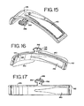
- FIG. 15 is a side view of one embodiment of the control valve showing the port.
- FIG. 16 is a concave perspective view of the slide control showing the port.
- FIG. 17 is a concave bottom view of the slide control showing the port.
- FIG. 18 is an exploded view of an alternative embodiment of the PP apparatus of FIGS. 8-10 .
- FIG. 19 is a cross-sectional view of the PP apparatus of FIG. 18 .
- FIG. 20 is a perspective view of a duck-bill valve used in the PP apparatus of FIGS. 18-19 .
- FIG. 21 is a cross-sectional view of the duck-bill valve of FIG. 20 .
- FIG. 22a is a front exploded view of one embodiment of the PP apparatus in conjunction with a mouthpiece and associable with a spacer.
- FIG. 22b is a rear exploded view of one embodiment of the PP apparatus in conjunction with a mouthpiece and associable with a spacer.
- FIG. 22c is a front view of one embodiment of a valve showing the baffle.
- FIG. 23 is a perspective view of one embodiment of a PP apparatus in association with a nebulizer.
- FIG. 24 is an exploded view of one embodiment of the PP apparatus and a mouthpiece.
- FIG. 25 is a perspective view of one embodiment of the PP apparatus in an open position and a mouthpiece.
- FIG. 26 is a perspective view of one embodiment of the PP apparatus in a semi-open position and a mouthpiece.
- FIG. 27 is an exploded view of one embodiment of the PP apparatus showing the disc and a mouthpiece.
- FIG. 28a is a top view of one embodiment of the PP apparatus and a mouthpiece.
- FIG. 28b is a cross section of one embodiment of the PP apparatus and a mouthpiece showing a plurality of prongs holding the PP apparatus.
- FIG. 29 is an exploded view of a PP apparatus associated with a mouthpiece and having an inhalation valve.
- FIG. 30 is an exploded view of a PP apparatus associated with a mouthpiece and having an exhalation valve.
- FIG. 31 is a further perspective view of one embodiment of the PP apparatus in conjunction with a mask having an opening for association with a chamber.
- FIG. 32a is a close up of one embodiment of the PP apparatus in a fully open position in conjunction with a mask.
- FIG. 32b is a cross section of one embodiment of the PP apparatus in a fully open position in conjunction with a mask.
- FIG. 33a is a close up of one embodiment of the PP apparatus in a partially open position in conjunction with a mask.
- FIG. 33b is a cross section of one embodiment of the PP apparatus in a partially open position in conjunction with a mask.
- FIG. 34a is a close up of one embodiment of the PP apparatus having a plurality of variable sized flow ports, in conjunction with a mask.
- FIG. 34b is a cross section of one embodiment of the PP apparatus having a plurality of variable sized flow ports, in conjunction with a mask.
- FIG. 35a is a front exploded view of a close up of one embodiment of the PP apparatus having a plurality of variable sized flow ports, in conjunction with a mask.
- FIG. 35b is a rear exploded view of a close up of one embodiment of the PP apparatus having a plurality of variable sized flow ports, in conjunction with a mask.
- FIG. 36 is a front view of one embodiment of the PP apparatus showing resistance setting indicia.
- FIG. 37 shows a perspective view of a spacer for a pressurized metered dose inhaler with one embodiment of the PP apparatus.
- FIG. 38a is a perspective view of one embodiment of the resistance window in the open position.
- FIG. 38b is a perspective view of the embodiment of FIG. 38a with the resistance window in a closed position.
- FIG. 39a is a perspective view of one embodiment of the resistance window in the open position.
- FIG. 39b is a perspective view of one embodiment of the resistance window in the closed position.
- FIG. 40 illustrates an alternative embodiment of the apparatus of FIGS. 37-39 .
- FIGS. 1-3 show one embodiment of an assembly 10 for performing positive expiratory pressure (PEP) therapy where the assembly incorporates a positive pressure (PP) device having a PP valve 12 .
- the assembly 10 includes an aerosol delivery apparatus, such as an aerosol holding chamber 14 , and a patient respiratory system interface, such as a mouthpiece 16 and/or mask attachable to the output end of the aerosol delivery apparatus.
- the PP valve 12 may be located on the aerosol delivery apparatus or the patient respiratory system interface.
- the assembly 10 combines the aerosol delivery apparatus, mouthpiece, and PP valve into a tool for use in both positive expiratory therapy and administration of a substance, such as a medicament, in aerosol form. Any aerosol delivery apparatus suitable for generating an aerosol of the desired substance may be used.
- a backpiece 18 is attachable to the inlet 20 of the aerosol holding chamber 14 .
- a metered dose inhaler (not shown) may be connected with the backpiece 18 .
- the mouthpiece 16 is attachable to the outlet end 22 of the aerosol holding chamber 14 .
- the PP valve 12 is generally locatable at the outlet end 22 of the aerosol holding chamber 14 .
- FIG. 3 depicts an exploded view of the PEP assembly showing an annular valve 24 positioned between the outlet end 22 and the mouthpiece 16 . More details on the aerosol holding chamber 14 disclosed in FIGS. 1-3 may be found in U.S. Pat. No. 4,470,412 and U.S. patent application Ser. No. 09/287,997 incorporated above.
- the aerosol holding chamber 14 is provided with an annular valve 24 located at its outlet end 22 .
- the annular valve 24 allows the user to inhale medicament from the chamber 14 , but prevents exhalation back through the chamber.
- a PP valve 12 may be formed in a mouthpiece 16 .
- the PP valve 12 includes a slide control 26 that is movably positioned relative to a resistance window 28 .
- the slide control 26 is variably maneuverable to cover or uncover the resistance window 28 in a continuous manner. Further, the movement of the slide control 26 includes, but is not limited to, covering or uncovering, and/or opening or closing, the resistance window 28 or any variations thereof.
- the PP valve 12 may be located on or in conjunction with a mouthpiece 16 .
- An exemplary embodiment of the mouthpiece 16 shown in FIGS. 4a-4f has a distal end 30 and a proximal end 32 .
- the proximal end 32 of the mouthpiece is inserted or associated with the mouth or nostrils of the user.
- the distal end 30 of a mouthpiece may or may not be associated with an aerosol delivery apparatus and the mouthpiece alone may be configured to constitute a PEP device.
- the PP valve 12 may be located at or near the distal end 30 of the mouthpiece 16 . Although, it is understood that the PP valve 12 may be located anywhere on the mouthpiece 1 and its location is not to be limited. In an alternative embodiment, the PP valve 12 may be located at or near the output end 20 of the aerosol delivery apparatus, such as, but not limited to, the aerosol holding chamber 14 of FIGS. 1-3 .
- the direction of travel of any fluid, particularly an aerosol or nebulizer medicament is in the direction from the input end 20 , through the channel or chamber body, and to or out the output end 22 . This direction of travel from input end 20 to output end 22 is referred to as travel from downstream to upstream.
- the mouthpiece 16 is formed of plastic.
- the plastic may be either rigid or soft.
- Other materials that can also be used for the mouthpiece 16 include metal or other materials known to one in the art.
- a tab 34 is provided allowing for the connection of a cap 36 , as shown in FIG. 2 , to cover the proximal end 32 of the mouthpiece 16 .
- the mouthpiece 16 may include indicia 35 , or setting indications, representing the resistance setting.
- the indicia 35 may be in the form of numbers, bars, colors, a series of dots or the like.
- the PP apparatus 10 may includes a fitting 39 sized for placement over the proximal end of the mouthpiece.
- the fitting 39 includes a manometer port 41 extending from the fitting over which a manometer can be attached.
- the fitting 39 is formed of a plastic.
- the plastic may be either rigid or soft. Other materials that can also be used to form the fitting include metal.
- FIGS. 3 , 8 a- 8 d and 9 show an embodiment of the slide control 26 of the PP apparatus 10 .
- the slide control 26 is of a semi-circular, quarter moon shape.
- the slide control 26 has a first lateral side 38 concave in shape and a second lateral side 40 opposite the first side 38 .
- the slide control 26 also has a top 42 and a bottom 44 surface. From the top surface 42 of the slide control 26 extends a tab setting 46 .
- the tab setting 46 is a uniformly molded projection from the slide control 26 .
- the tab setting 46 has smooth edges for easy engagement with the finger, thumb or appendix of the user.
- the tab setting 46 may also have a serrated edge or any other edge known in the art.
- the tab setting 46 projects through the mouthpiece from the tab window 48 .
- the user of the device manipulates the tab setting 46 in such a manner as to cause, either directly or indirectly, the movement of the slide control 26 thereby varying the opening of the resistance window 28 .
- the tab window 48 is arcuate in shape, parallel to the contour of the circumference of the mouthpiece 16 .
- the slide control 26 is preferably seated in a channel 50 located on the mouthpiece 16 .
- the slide control 26 is held within the channel 50 by at least one tooth 52 .
- Located on one or both of the walls of the channel 50 is a stepped surface 54 as shown in FIG. 5 .
- the control arm 56 of the slide control 26 is shown having a finger protection 58 from one end of the slide control 26 .
- the slide control 26 may have a control arm 56 located on both ends of the slide control 26 .
- the finger projection 58 is capable of engagement with the stepped surface 54 inside the mouthpiece shown in FIGS. 4c and 5 .
- the stepped surface 54 includes a series of ribs extending a variable length of the internal diameter of the mouthpiece 16 .
- the stepped surface 54 may also be located along the tab window 48 . Therefore, the location of the stepped surface 54 may vary while remaining engageable by the control arm 56 .
- the stepped surface 54 may be located on either or both of the internal walls of the channel 46 .
- the slide control 26 is of a flexible material so that the control arm 56 can slide across the uppermost surface of the ribs projecting from the stepped surface 54 .
- the control arm 56 engages in a semi-locked manner the ribs projecting from the stepped surface 54 .
- the end of the slide control 26 opposite the control arm 56 may either be provided with a finger projection 58 or may be smooth.
- the length of the slide control 26 extending from the tab setting 46 to the end of the control arm 56 opposite the projection 58 is generally the length of the resistance window 28 .
- This resistance control length 60 is at least the length that the resistance window 28 can be opened allowing for exhalant to exit the window 28 .
- the slide control 26 is manufactured of a plastic.
- the plastic may be either rigid or soft.
- Other materials that can also be used for the slide control 26 include metal or other materials known in the art.
- the resistance window 28 may be an opening of any size or shape in the walls defining the channel 46 in the mouthpiece 16 which, in conjunction with the illustrated embodiment of the slide control 26 , provides an opening in the mouthpiece 16 to produce sufficient pressure during exhalation of the patient performing PEP therapy.
- the resistance window 28 may be formed with straight or slanted edges. If the edges are slanted, this provides a steeped effect to the resistance window 28 . If the desired exhalation pressure is determined to range from 10-20 cm H 2 O, then the resistance window 28 in conjunction with the slide control 26 , acting as a cover or closure mechanism for the resistance window 28 , are sized in such a manner as to provide an appropriate opening for the desired exhalation pressure to be produced.
- the length of the window may be of a longer length so as to provide a large enough opening through which PEP therapy is performed.
- the resistance window length 60 of the control arm 26 is generally longer to cover the desired amount of the resistance window 28 .
- the control arm 26 may provide a continuously adjustable variable resistance window between a first position where the control arm completely blocks the window 28 , to a second position where the control arm leaves the window completely open.
- FIGS. 10-17 An alternative embodiment of an assembly 100 for performing PEP therapy is shown in FIGS. 10-17 .
- This embodiment is similar to the embodiment of FIGS. 11-13 , but utilizes a variation of the resistance window and slide control in the PP valve 112 .
- the resistance window 128 and slide control 126 are positioned in the mouthpiece 116 .
- the tab setting 146 of the slide control 126 is of a flexible material.
- a detent 158 protrudes from the first tab setting face 156 located on the concave side 125 of the slide control 126 .
- a position indicating rib 159 is located on the tab setting 146 opposite the detent 158 .
- the rib 159 is shown as a generally rectangular protrusion from the surface of the tab setting 146 .
- the rib 159 may be any shape protrusion, such as but not limited to circular, triangular.
- the rib 159 may not be a protrusion at all but rather is a concave marking on the surface of the tab setting 146 .
- the rib 159 has at least the function of indicating to the user the extent of the opening of the resistance window 128 . Therefore, one skilled in the art can envision a variety of marking, shapes, indents or protrusions, or colors which serve at least the function of indicating the extent of the opening of the resistance window 28 .
- the detent 158 located on the tab setting 146 is associated with at least one detent notch 154 as shown in FIGS. 10 and 14 .
- the flexible tab setting 146 is movable within the tab window 148 .
- the one or more detent notches 154 are preferably located along the boundary of the tab window 148 and indicia 135 , representative of exhalation effort corresponding to the position of the slide control 126 , are arranged adjacent the respective detent positions.
- FIGS. 10 and 14 show a plurality of detent notches 154 .
- the flexible tab setting 146 is moved along the tab window 148 .
- the detent 154 located on the first tab fitting face 125 of the tab setting 146 moves into and out of engagement with the detent notches 154 .
- Movement along the boundary and engagement with the detent notches 154 removably fixes the slide control 126 in a variety of positions. Each varied position provides for a further opening or closing of the resistance window 128 .
- the detent 158 is not limited to being engaged with a detent notch but may be engaged or seated at any point along the boundary. Engagement with, or seating within, a detent notch 154 of a detent 158 provides for a variable securely fixed opening of the resistance window 128 .
- Each detent notch 154 may correspond to a particular size opening or pre-set opening of the resistance window 128 . Therefore, by engagement of the detent 158 within the detent notch 154 , the user may be provided with a preset resistance window opening 128 . Yet, the detent notch 154 may also be positioned anywhere along the boundary providing for a continuously variable resistance window opening 128 .
- the slide control 126 as shown in FIGS. 15 , 16 and 17 has located therein a port 143 .
- the port 143 may be of any size or shape and in the illustrated embodiment is generally a rounded triangle having an elongated point.
- the port 143 operates in conjunction with the resistance window 128 .
- the size of the opening through which the exhalant passes is determined by how much of the port 143 is left uncovered or open and aligned with the resistance window 128 .
- the slide control 126 is provided with a closure area 145 , as shown in FIG. 16 . Further, the slide control 126 is provided additionally with a port area 160 .
- the closure area 145 of the slide control 126 is congruent with or aligned with the resistance window 128 .
- the port area 160 containing the port 143 is brought into alignment with the resistance window 128 in the mouthpiece 116 .
- a continuously variable opening is provided. For example, as the slide control 126 moves aligning a greater and greater amount of the port 143 with the resistance window 128 , a greater opening or path for the exhalant is provided.
- the slide control 126 is seated in a channel 150 located on the mouthpiece 116 .
- the slide control 126 is slidably movable within the channel 150 in the manner described above so as to continuously variably align the port 160 with the resistance window 128 .
- a retaining ridge 162 fits into the channel 150 thereby holding the slide control 126 in its desired position throughout its range of motion in the mouthpiece.
- the desired position of the slide control 126 is as close as possible to the annular sealing ring 164 shown in FIG. 13 .
- the annular sealing ring 164 may optionally be provided with at least one locating ring or post 166 to help maintain the slide control 126 in alignment.
- a patient's exhalation effort is controlled by adjusting the slide control over the resistance window so that the patient's exhaled air, which is prevented from entering the aerosol chamber 114 by the annular valve 124 and a baffle (not shown), must exit through the resistance window and provide a desired exhalation resistance. More specifically, during inhalation the inner diameter 127 of the annular valve 124 ( FIG.
- the exhalation flange 186 of the valve 124 flexes to seal against the outer ridge 188 ( FIG. 13 ) formed inside the mouthpiece 116 to prevent ambient air from entering the mouthpiece.
- the process is reversed and the inner diameter 127 prevents exhalant from entering the aerosol holding chamber while the exhalation flange 186 flexes away from the outer ridge 188 .
- the exhalant preferably passes through the resistance window 128 and may escape to the outside between the exhalation flange and the mouthpiece, and then through the gap between the mouthpiece and aerosol holding chamber.
- the aerosol delivery apparatus includes a chamber housing 214 having an input end 220 and an output end 222 .
- the chamber housing 214 , input end 220 , and output end 222 define an interior space 223 .
- the apparatus may also include an elastomeric backpiece which may be similar to the backpiece in the embodiment shown in FIGS. 1-3 .
- the output end 222 of the chamber housing 214 is shaped to receive the mouthpiece 216 and includes locking tabs 281 and a protrusion 283 .
- the protrusion 283 is preferably annular in shape.
- the locking tabs 281 are spaced apart around the outside of the output end 222 .
- the mouthpiece assembly 216 is preferably substantially similar to that illustrated in FIGS. 10-15 .
- the mouthpiece assembly includes an annular sealing ring 224 , and a resistance window defined by a gap 225 in the sealing ring.
- a slide control 226 is slidably seated in a channel 250 between the annular sealing ring and support posts or a support ring.
- the tab setting 246 protrudes from the tab window 248 in the mouthpiece 216 .
- the continuously variable resistance function is achieved as described above, using either embodiment of slide control and nozzle described above.
- a containment baffle 275 may be integrally formed with the chamber housing 214 from a single piece of material and located near the outlet end 222 .
- the containment baffle 275 includes connecting members 276 that extend from the edge of the containment baffle to the inner diameter of the output end 222 in the chamber housing. Vents 277 are defined between the outer perimeter of the containment baffle and the inner diameter of the outlet end of the chamber housing and are separated by the connecting members.
- vents 277 are arcuate in shape and conform to the outer perimeter of the containment baffle 275 .
- the containment baffle is dome-shaped where the concave end points towards the chamber 223 .
- the containment baffle may be any of a number of geometric shapes.
- a valve 278 having a valve member 279 and a valve seat 280 is shown.
- the valve seat 280 preferably comprises the rim of the valve and the corresponding raised lip 283 on the outlet end 222 of the chamber housing 214 .
- the valve member has a sealing surface that preferably forms between two parallel portions, or lips, of the valve.
- the valve material seals against itself when fluid flows against a predetermined flow direction of the valve.
- the valve is a duck-bill valve where the valve seat 280 is positioned axially away from the valve opening.
- the valve 278 defines a central open area toward the end having the valve seat.
- the valve member 279 shown as parallel sealing lips in FIGS.
- valve seat 280 also provides a seal against the chamber housing 214 during exhalation so that exhalant from a patient must be directed through the continuously variable resistance window in the mouthpiece.
- the duck-bill valve 278 has a central open area 274 at its base that has a diameter of approximately 26.09 millimeters (mm).
- the width of the lips that form the valve member 279 is approximately 21.35 mm and the angle at which the walls 285 converge is approximately 72 degrees.
- the height of the duck-bill valve 278 measured from the upper portion 282 of the valve seat to the valve member 279 is approximately 18.8 mm.
- the mouthpiece 216 for containing this valve 278 preferably includes a resistance widow gap 225 having a length of 59 degrees of arcuate cut in the annular sealing ring 224 , where the annular sealing ring is approximately 31.4 mm in diameter and has a height of 4.5 mm.
- valve is adjacent to the output end of the chamber housing.
- annular valve embodiment of FIGS. 1-3 and 10 - 17 the inner portion of the valve covers the vents at the outlet end of the chamber housing.
- duck-bill embodiment of FIGS. 18-21 the entire outlet end is covered by the valve.
- the mouthpiece and outlet end of the chamber housing traps the valve in place. Inhalation by the patient causes the sealing portion of the annular valve to move, or alternatively the lips of the duckbill valve to separate, and permit fluid to pass. Fluid from the chamber housing may be inhaled into the patient's respiratory system through the mouthpiece. The patient may then exhale into the mouthpiece.
- Exhalation by the patient results in air traveling through the mouthpiece in a direction opposite the predetermined inhalation flow path of the valve.
- This air which is blocked from passage through the valve along the inhalation path, then passes along a second path through the resistance window in the mouthpiece.
- the force of the exhaled air causes the outer portion of the valve to move away from the mouthpiece in a direction towards the chamber housing.
- an exhalation pathway is created between the outer portion of the valve and the mouthpiece through which the exhaled air passes out to the atmosphere or some other predetermined location.
- the amount of effort that exhalation requires is set by the slide control, which may be set to block the appropriate amount of the resistance window to achieve the desired resistance.
- the duck-bill valve 278 assists both in preventing inhalation of ambient air through the resistance window 225 and providing an exhalation path for exhalant.
- the upper portion 282 of the valve seat seals against the annular sealing ring 224 except for the gap in the annular sealing ring 224 defining the resistance window 225 .
- fluid flows through the central opening 274 and out the lips of the valve member 279 .
- the exhalation flange 286 flexes toward the proximal end of the mouthpiece and provides a secondary seal against the outer ridge 288 inside the mouthpiece.
- the outer ridge 288 is preferably continuous around the inner circumference of the mouthpiece. Upon exhalation, the lips of the valve member 279 close, the exhalant passes through the resistance window under the upper portion 282 of the valve seat positioned adjacent the resistance window opening, and the exhalation flange flexes away from the outer ridge 288 and out between the aerosol holding chamber 214 and mouthpiece 216 .
- an embodiment of an apparatus 310 for performing PEP therapy is disclosed that may be used with or without an aerosol delivery apparatus.
- the PEP apparatus of FIGS. 22a-22c is a standalone PEP device in a mouthpiece incorporating the previously discussed continuous variable resistance window with slide control, and variations thereof, along with a self contained valve 378 that may be similar to that disclosed in the previous embodiments.
- the valve 378 need not be found on the outlet end of a separate chamber extension 314 but may be positioned on the distal end 330 of the mouthpiece.
- the valve 378 may be an annular valve.
- the 378 is preferably retained toward the distal end 330 of the apparatus by a central baffle 385 supported by radial spokes 386 .
- the PEP apparatus 310 is formed of an attachable mouthpiece section 316 and a baffle section 317 .
- the mouthpiece and baffle sections 316 , 317 may be removably joined using snap-fit, threaded or other known attachment schemes.
- the mouthpiece and baffle sections 316 , 317 may be integrally molded or welded shut to form a non-removable, unitary piece.
- An extended inlet 314 without any valves, may be used with the stand-alone PEP device 310 to enhance delivery of any medicine to the patient's respiratory system.
- One function of the extended inlet is to provide a chamber for the dispensed particles from the pressurized metered dose inhaler.
- a pressurized metered dose inhaler may be coupled to the extended inlet with a backpiece and medicament supplied from the pressurized metered dose inhaler can be delivered directly to the user.
- FIGS. 1-22 illustrate annular and duck-bill valves 24 , 124 , 278 , 378
- a preferred valve is capable of passing a fluid moving in a first direction along a first path and also capable of passing a fluid moving in an opposite direction along a second path.
- inhalation draws fluid through a central opening in the valve while the perimeter of the valve prevents fluid flow.
- exhalation closes the path through the central opening and directs fluid along a second path around the perimeter of the valve.
- Other paths may also be used.
- FIGS. 23-28 illustrate another embodiment of a PEP apparatus 410 .
- the PEP apparatus 410 has a patient respiratory system interface, such as a mouthpiece 416 , on a proximal end 432 and may be connected with an aerosol delivery apparatus, in this example a nebulizer 414 , at a distal end 430 .
- the PEP apparatus includes a PP valve 412 positioned on top of the mouthpiece 416 .
- the PP valve 412 preferably consists of a cover 417 that may be removably attached to a receiving area 419 ( FIG. 24 ) on the mouthpiece 416 .
- the cover has a resistance window 428 and a tab window 448 extending through a top surface.
- a slide control 426 in the form of a disk with vents 460 extending through the thickness of the disk is movably positioned under the cover 417 .
- a one-way valve 423 is positioned between the slide control 426 and the top of the mouthpiece 416 to allow air exhaled into the proximal end 432 to escape through the resistance window 428 while preventing any air from entering through the resistance widow during inhalation.
- the resistance window 428 is shown generally as a pie-slice shaped cut-out with the point of the pie-slice removed so as to form a concave edge.
- the resistance window 428 may be any shape and should not be limited by the illustrated embodiment.
- a plurality of resistance windows 428 may form the PP valve 412 .
- the number of windows 428 is not intended to be limited by the illustrated embodiment.
- the slide control 426 is shown as a circular disc having a pie-slice shaped cut-outs with the point of the pie-slice openings therein which correspond to the openings of the resistance window 428 .
- aligning the openings 460 of the disc with the resistance window 428 controls the opening of the continuously variable resistance window 428 .
- the resistance windows 428 are aligned with the disc openings 460 , the resistance windows 428 are opened to their fullest extent allowing the resistance of the exhalant exiting the PP valve 412 to be lower.
- the resistance of the exhalant exiting the PEP apparatus 410 is increased.
- the vents may be adjusted in the disk 417 to any of a number of positions, thereby providing a continuously adjustable resistance. In this manner, positive expiratory pressure is controlled.
- nebulizer Upon inhalation, the nebulizer will provide an aerosol to the inhaling patient via the mouthpiece.
- a suitable nebulizer for use with the PEP apparatus 410 is a breath-actuated nebulizer such as disclosed in U.S. Pat. No. 6,044,841 issued Apr. 4, 2000 and entitled “Breath Actuated Nebulizer with Valve Assembly Having Relief Piston”, the entirety of which is incorporated herein by reference.
- a piston 452 is drawn down by negative pressure created by the inhalation in the nebulizer and ambient air is drawn through openings 454 in the lid 456 of the nebulizer 414 .
- the one-way valve 459 in the PP valve assembly 412 remains shut during inhalation.
- a positive pressure builds in the nebulizer 414 and the piston acts as a one-way valve to close off the flow of air out of the nebulizer.
- the exhalant must travel through the one-way valve in the PP valve assembly 412 , through the slide control and out the resistance window.
- the slide control 426 under the resistance window 428 has been set to the appropriate position for the patient so that effective PEP therapy may be provided.
- the PEP apparatus of FIGS. 23-27 uses an aerosol delivery apparatus such as the nebulizer 414 to restrict air flow through any opening other than the PP valve assembly 412 , other embodiments, such as shown in FIG.
- FIGS. 23-28 show an improved nebulizer 414 associated with a PEP apparatus 410 having a PP valve 412 .
- the nebulizer may be used alone or in combination with a mouthpiece mounted PP valve 412 or mask mounted version of the PP valve discussed below.
- FIG. 29 shows an alternative embodiment of the PEP apparatus 410 of FIGS. 23-28 that may be used alone or coupled to a nebulizer or other aerosol delivery apparatus.
- the mouthpiece 462 is provided with a one-way inhalation valve assembly 463 having a membrane 464 captured in an outlet cover 465 attached to the distal end 466 of the mouthpiece.
- the flexible membrane preferably covers vents in the outlet cover 465 during exhalation and flexes to allow fluid flow during inhalation.
- a PP valve assembly 467 is positioned on top of the mouthpiece. The PP valve assembly 467 differs from the PP valve assembly 412 in FIGS.
- the slide control 468 contains a circular opening 469 that is moved by the tab setting 469 under a tear-drop shaped resistance window 471 in the cover 472 .
- the inhalation valve 463 allows for fluid to enter the mouthpiece 462 but prevents fluid from exiting the mouthpiece.
- the exhalation valve 473 allows for exhalation through the resistance window 471 but prevents inhalation of particles or fluid. When assembled, a gap is present between the exhalation valve 473 and the slide control 468 in order to allow the exhalation valve 473 to open upon exhalation. In this manner, the mouthpiece 462 is adapted to be used alone and not in conjunction with a nebulizer or other aerosol delivery apparatus.
- FIG. 30 shows one embodiment, similar in concept to the embodiment of FIG. 29 , but with the PP valve 475 attached in series with the one-way inhalation valve 476 , rather than in series with the one-way exhalation valve, to provide for resistance upon inhalation only.
- the arrows drawn in FIG. 30 depict the direction of travel from the downstream end of the mouthpiece 478 to the upstream end of the mouthpiece showing that all inhalation must pass through the continuous variable resistance window 480 and the port 482 of the slide control 484 .
- PP valves may be placed in series with both the one-way input and one-way output valves to allow for simultaneous control of positive inspiratory and expiratory pressures at the same or different levels.
- FIGS. 31-35 A PP apparatus 510 utilizing a mask 512 as the interface is illustrated in FIGS. 31-35 .
- the mask may be a standard mask sized for adults or children and constructed of any of a number of materials such as silicon rubber.
- the mask 512 may have a frustoconical shaped main section 514 sized to cover the patient's mouth and a nosepiece section 516 sized to cover a patient's nose.
- a central opening 518 in the mask 512 may be used to attach with an aerosol delivery apparatus such as the aerosol holding chamber 14 shown in FIGS. 1-3 , and other aerosol delivery apparatus.
- the mask 512 may be fitted with a one-way valve in the central opening 518 for use as either a positive expiratory pressure device or a positive inspiratory pressure device.
- a PP valve assembly 520 is positioned on the device so that inspiration and exhalation paths travel off-axis from one another.
- the PP valve assembly 520 has an adjustable valve assembly cover 534 with tab window 522 and resistance window 528 openings positioned on it.
- the resistance window 528 is generally an oblong, tear-drop shape and the tab window 522 defines an arcuate opening in the PP valve cover 534 .
- the tab window and resistance window may alternatively be rectangular, oval or any other shape.
- the PP valve assembly 520 has a fixed opening 530 and a set of detents 532 positioned on a disk-shaped platform 526 that connects to the nosepiece section of the mask through complementary tab 542 and slot 544 connectors.
- the PP valve cover 534 has a protrusion 536 sized to cooperate with the detents 532 on the platform 526 so that the valve cover may be moved to predetermined spots when the valve cover is rotated against the platform.
- An axle 538 on the valve cover fits into a central opening 540 in the platform 526 so that the resistance window 528 is rotatably positionable over the exhalation port 530 and the tab window 522 lines up with the tab extending from the platform 526 .
- This embodiment depicts the resistance window 528 as a curved tear-drop like shape.
- the platform 526 is shown as a circular disc having at least one port opening 530 .
- the port opening 530 may vary in size and shape.
- the opening formed for the exhalant to pass through is related to the alignment of the resistance window 528 with the port opening 530 .
- the resistance window is moveably mounted relative to a fixed slide control portion attached to the mask.
- Tabs 542 on the platform 526 preferably mate with tab receiving regions 544 on the end of the nosepiece section 516 to retain the platform in a fixed position relative to the mask. Moving the tear-drop shaped resistance window 528 past the part opening 530 vanes the exhalant path.
- a plurality of resistance window openings 528 may be moved past the port 530 .
- one end of the tear-drop shaped resistance window 528 matches the size of the largest port opening 530 at a maximum flow position thereby providing a maximum flow and least resistance in that position.
- the valve cover is rotated so that the resistance window 528 covers a greater portion of the port, as shown in FIGS. 33a-33b , a smaller exhalant path is created providing greater resistance.
- moving the valve cover until the tab reaches the opposite end of the tab window results in the smallest amount of the port being open, the highest airflow resistance and the least flow.
- FIG. 36 an embodiment is shown of a valve cover 550 having indicia 552 representative of a resistance setting.
- the indicia 552 are arranged to cooperate with the tab extension 554 on the platform to indicate the current resistance setting.
- PEP therapy maybe performed with a mouthpiece or mask having the PP valve associated with a backpiece.
- the mask or mouthpiece may have an extended inlet for association with the backpiece.
- pressurized metered dose inhalers are generally cylindrical canisters 700, as shown in FIG. 18, with axially extending vent tubes from internal valves.
- pressurized metered dose inhalers When the external tube or stem of a pressurized metered dose inhaler canister 700 is depressed it operates the internal valve to dispense a measured dose of medicine from the stem.
- the medicine is commonly packed in the canister with a suitable compressed gas to propel the medicine and gas from the stem or tube when the later is depressed.
- the medicine may be in gas, liquid, or solid form.
- the manufacturer or distributor of the pressurized metered dose inhaler canister generally supplies it with a substantially L-shaped adapter 602 which receives the canister in a substantially upright position, and has a substantial horizontal outlet portion for reception in the mouth of an asthmatic patient for inhalation of the medicine.
- a spacer chamber with an integrated actuator, or an aerosol holding chamber have been used in attempts to overcome inappropriate particle size.
- the aerosol holding chamber is generally provided at the upstream or entering end with a flexible, resilient adapter or backpiece made of rubber or the like material.
- a central aperture is provided for receipt of the horizontal outlet portion of the pressurized metered dose inhaler adapter.
- a PP apparatus 600 may be associated with the pressurized metered dose inhaler or the pressurized metered dose inhaler with an aerosol holding chamber.
- an L-shaped adapter portion 602 holds the pressurized canister and a horizontal outlet section 604 receives the medicament released in aerosol form.
- a one-way valve 606 which may be a flexible membrane, a rigid membrane, hinged door, or other commonly known valve mechanism is positioned at the proximal end 608 of the horizontal outlet section 604 .
- the one-way valve 606 permits inhalation and blocks exhalation so that substantially all exhalation is routed through the variable resistance window 610 adjacent the one-way valve 606 .
- a slide control 612 is movable in the resistance window 610 by a tab 614 to close off or open up as much of the resistance window as necessary to provide the desired expiratory pressure.
- FIGS. 38a and 39a illustrate the slide control in a completely open position and FIGS. 38b and 39b illustrate the slide control closing off the resistance window.
- the slide control may maintain its position in the resistance window through friction, detents or other known mechanisms for mechanically retaining one of multiple desired positions.
- FIG. 40 illustrates another embodiment of a pressurized metered does inhaler 620 with a round proximal end 628 that may be used without the need for special mouthpieces or aerosol holding chambers.
- the alternative PEP enabled pressurized metered dose inhaler 620 has a one-way valve 626 that shunts exhalant through a resistance window 622 that is continuously adjustable with a slide control 624 that can adjust the aperture of the resistance window.
- a mouthpiece or mask may be associated the PP apparatus.
- an aerosol holding chamber may be attached to the mouthpiece or mask end and a metered dose inhaler may be positioned on a generally opposite end of the chamber via a backpiece.
- the user of the device may insert the mouthpiece into the mouth to obtain a dose of medicament. Further, the user may place the mask over the mouth and/or nose to inspire a dose of the medicament. In either situation, the mask or mouthpiece aids in the delivery of the medicament to the user.
- a method and apparatus from providing positive expiration or inhalation therapy, with or without separate aerosol generating devices has been disclosed.
- the positive expiratory pressure valve is located at or near the output end of the aerosol delivery apparatus
- a one way inhalation valve can be located further downstream from the positive expiratory pressure valve.
- a mouthpiece and or mask can be affixed at or near the output end of the aerosol delivery apparatus.
- the positioning of the inhalation valve either upstream or downstream in respect to the positive expiratory pressure valve is well known to one skilled in the art. Further, it is envisioned that PEP therapy may be performed nasally with the positive expiratory pressure apparatus.
- a one way inhalation valve is engageable with the mouthpiece.
- the inhalation valve functions so as to allow for inhalation by the patient into the mouthpiece.
- the exhalant of the patient is prevented from exiting via the inhalation valve and is directed to exit through the PP valve.
- an inhalation valve opens upon inhalation to allow a fluid, such as an aerosol, to enter a chamber or channel or the like but that closes upon exhalation to prevent exhaled fluids to enter into the chamber of the like.
- the drawings depict an exemplary embodiment of the one-way inhalation valve but are not to be limiting to the embodiments shown.
- a physician may initially determine the proper resistance setting of the PP apparatus according to the patient's requirements.
- One manner in which the PP apparatus may be properly set is by attaching a fitting 39 to the mouthpiece.
- a manometer is then attached to the fitting port 41 and serves to measure the expiratory pressure.
- a patient will exhale into the mouthpiece and the pressure can be read from the manometer.
- the physician can the move the tab to one of the desired settings indicated on the mouthpiece.
- the fitting 39 can be removed from the mouthpiece. This fitting 39 will not be used again unless it is determined that the resistance should be adjusted.
- the method of performing PEP therapy using the PP apparatus includes performing a series of breaths. When exhalation is performed, the exhalant is directed through the continuously variable expiratory window. Performance of a therapeutic cough triggers the loosening of secretions. Upon loosening of the secretions, a medicament may be provided for inhalation into the respiratory system. In one embodiment of PEP therapy, the user will exhale into the mouthpiece and/or mask, against the desired resistance. This is done either prior to or in combination with inhalation of the medicament. The exhaled gases exit through the resistance window. This process may be repeated as many times as prescribed by the patient's physician.
- the aerosol delivery apparatus with the PP apparatus may be used alone or in combination with a mask or mouthpiece. Also, an improved aerosol delivery apparatus with an integrated actuator has been shown, wherein the improvement comprises a PP valve.
- the discussion above is descriptive, illustrative and exemplary and is not to be taken as limiting the scope defined by any appended claims.
Landscapes
- Health & Medical Sciences (AREA)
- Engineering & Computer Science (AREA)
- Pulmonology (AREA)
- General Health & Medical Sciences (AREA)
- Life Sciences & Earth Sciences (AREA)
- Public Health (AREA)
- Heart & Thoracic Surgery (AREA)
- Hematology (AREA)
- Anesthesiology (AREA)
- Animal Behavior & Ethology (AREA)
- Veterinary Medicine (AREA)
- Biomedical Technology (AREA)
- Bioinformatics & Cheminformatics (AREA)
- Emergency Medicine (AREA)
- Physical Education & Sports Medicine (AREA)
- Measurement Of The Respiration, Hearing Ability, Form, And Blood Characteristics Of Living Organisms (AREA)
- Respiratory Apparatuses And Protective Means (AREA)
- Pharmaceuticals Containing Other Organic And Inorganic Compounds (AREA)
Abstract
An apparatus and method for performing positive pressure (PP) therapy alone or in combination with an aerosol delivery apparatus. The positive pressure apparatus includes a positive pressure valve having a continuously variable respiratory window. The PP valve may be associated with a patient respiratory system interface alone, such as, but not limited to, a mask or mouthpiece, or in combination with an aerosol delivery apparatus.
Description
Notice: More than one reissue application has been filed for the reissue of U.S. Pat. No. 6,848,443. The reissue applications are Ser. Nos. 11/655,039 (now U.S. Pat. No. Re. 43,174) and 13/371,787.
This application is a continuation reissue of U.S. application Ser. No. 11/655,039, filed Jan. 18, 2007, now Reissue U.S. Pat. No. Re. 43,174, which application is a reissue of U.S. application Ser. No. 10/389,257, filed Mar. 14, 2003, now U.S. Pat. No. 6,848,443, which is a continuation of U.S. application Ser. No. 09/833,019, filed Apr. 11, 2001, now U.S. Pat. No. 6,557,549, which claims the benefit of U.S. Provisional Application No. 60/196,555, filed Apr. 11, 2000, wherein the entirety of each of the aforementioned applications are incorporated herein by reference.
The invention relates to an apparatus and method for performing Positive Expiratory Pressure (PEP) therapy. More particularly, this invention relates to a method and apparatus for performing PEP therapy alone or in conjunction with an aerosol delivery apparatus.
PEP therapy is used primarily in pulmonary secretion removal. Devices used to perform PEP therapy provide positive pressure during expiration. The patient or user exhales against a fixed orifice resistor and generates a pressure ranging approximately from 10-20 cm H2O. The resistance orifice is an important consideration and frequently is initially set by a physician, veterinarian, or a skilled practitioner in the art. An orifice that is too large may result in a short exhalation that will not produce proper expiratory pressure. An orifice that is too small may result in a longer expiratory phase that raises the pressure above approximately 20 cm H2O and ultimately increases the work of breathing.
During the exhalation phase of PEP therapy, the airway is splinted open by the pressure. This causes the movement of secretions from the peripheral airways into the larger airways where they can be expelled. PEP therapy usually lasts for about 10-20 minutes and is performed as required, generally 1-4 times per day. Typically, the patient performs 10-20 PEP breaths, removes the device from their mouth and follows this with a forceful exhalation. This final exhalation triggers a cough that loosens secretions.
Studies indicate that PEP therapy dilates the airways and improves the distribution of ventilation, resulting in a better deposition of an inhaled substance, such as, but not limited to, a medicine or remedy. As used herein, the term “aerosol delivery apparatus” means any apparatus capable of producing and/or delivering a substance, such as, but not limited to, a medicine, in a form suitable for inhalation by a patient and includes, without limitation, an aerosol holding chamber, nebulizer, spacer with integrated actuator, a dry powder inhaler, and a metered dose inhaler.
One aspect of the present invention is directed to a positive respiratory pressure apparatus including a patient respiratory system interface and a valve assembly in fluid communication with the patient respiratory system interface. The valve assembly has a valve configured to pass a fluid traveling in a predetermined direction from a first side to a second side of the valve, and a variable resistance bypass window positioned adjacent the valve and having a resistance to a fluid traveling in a direction opposed to the predetermined direction, where the variable resistance bypass window is continuously adjustable between a first fluid resistance and a second fluid resistance.
According to another aspect of the invention an apparatus is disclosed that is capable of performing positive expiratory pressure (PEP) therapy alone or in combination with providing a substance, generally in aerosol form. The apparatus includes a positive pressure (PP) valve having a continuously variable respiratory window. As used herein, the term respiratory is intended to encompass both inhalation and exhalation. Whether inhalation resistance or exhalation resistance is called for will be known to one skilled in the art. The valve may be located at or near the output end of an aerosol delivery apparatus. U.S. application Ser. No. 08/938,686 filed Sep. 26, 1997 in the name of Engelbreth et al. and Ser. No. 09/287,997 filed on Apr. 7, 1999 in the name of Schmidt et al. describe exemplary embodiments of an aerosol delivery apparatus and the disclosures of these references are incorporated herein by reference. Further, U.S. Pat. No. 4,470,412 to Nowacki et al., describing a spacer or expansion chamber, is additionally incorporated herein by reference. The aerosol delivery apparatus with the PP apparatus may be used alone or in combination with a mask or mouthpiece.
In one embodiment, the PP apparatus is associated with a mask. The mask with the PP apparatus may be used alone or in combination with an aerosol delivery apparatus. In another embodiment, the PP apparatus is associated with a mouthpiece. The mouthpiece with the PP apparatus may be used alone or in combination with an aerosol delivery apparatus. In a further embodiment, the PP apparatus is associated with a nebulizer. The nebulizer with the PP apparatus may be used alone or in combination with a patient respiratory system interface, such as a mask or mouthpiece. In yet another embodiment, the PP apparatus is associated with a spacer chamber with an integrated actuator. The spacer chamber with the integrated actuator associated with the PP apparatus may be used alone or in combination with a mouthpiece or mask.
In another embodiment, a pressurized metered dose inhaler canister is capable of association with an aerosol holding chamber having a PP valve associated therewith. In yet a further embodiment, a pressurized metered dose inhaler canister is capable of association with an aerosol holding chamber engageable with a mouthpiece or mask having a PP valve associated therewith.
Another aspect of the invention is directed to a kit for performing positive expiratory pressure including an aerosol delivery apparatus, a mouthpiece and/or mask attachable to the output end of the aerosol delivery apparatus, and a PP apparatus. The PP apparatus may be located on the aerosol delivery apparatus or the mouthpiece and/or mask. In alternative embodiments, the PP apparatus may be attached to the aerosol delivery apparatus or integrally formed with the apparatus. The aerosol delivery apparatus, mouthpiece, and PP valve can be combined so as to accomplish positive expiratory therapy and administration of a substance, such as, but not limited to, a medicine in aerosol form. Any aerosol delivery apparatus may be used. In further embodiments of the kit, a backpiece is included for association with an aerosol delivery apparatus. A pressurized metered dose inhaler can engage with the backpiece for delivery of a medicament.
One embodiment of a method of performing positive expiratory pressure therapy includes providing a PP apparatus with a valve that is capable of providing a continuously variable expiratory window. The method further includes performing a series of breaths. When exhalation is performed, the exhalant is directed through the continuously variable expiratory window. Performance of a therapeutic cough triggers the loosening of secretions. Upon loosening of the secretions, a substance, such as a medicament, may be provided for inhalation into the respiratory system. In an alternative embodiment of method, the PP valve may be positioned so as to provide positive inspiratory pressure upon inhalation into the apparatus.
A further aspect of another embodiment includes association of a PP apparatus associable with a mask or mouthpiece engageable with a backpiece device. The backpiece device includes a plastic or an elastomeric adapter suited to receive the mouthpiece of a pressurized metered dose inhaler.
One embodiment of a method of performing positive expiratory pressure therapy includes providing a positive expiratory pressure apparatus having a valve capable of providing a continuously variable resistance window, performing a series of breaths including inhalation and exhalation; exhaling so that the exhalant is directed through the continuously variable resistance window, performing a therapeutic cough triggering the loosening of secretions, and providing an inhaleable medicament.
Another embodiment of a method of performing positive expiratory pressure therapy includes providing a positive respiratory pressure apparatus having a valve capable of providing a continuously adjustable resistance to exhalation, where the valve is located in a mouthpiece attachable to a chamber. A patient then executes a series of therapeutic breaths, including inhalation and exhalation, wherein the exhalant is directed through the continuously adjustable resistance window, the patient performs a therapeutic cough triggering the loosening of secretions, and medicament is provided via the chamber.
According to another aspect of the invention, a method of performing positive expiratory pressure therapy in combination with providing an aerosolized medicament includes providing a positive expiratory pressure apparatus having a positive expiratory pressure valve capable of providing a continuously variable resistance window, where the valve is positionable in a mouthpiece and the mouthpiece attachable to an aerosol holding chamber. A series of therapeutic breaths, including inhalation and exhalation, are then taken where the exhalant is directed through the continuously variable resistance window. The continuously variable resistance window is preferably capable of providing a variable back pressure to the exhalant. A therapeutic cough capable of triggering the loosening of sections is performed and aerosolized medicament from the aerosol holding chamber is administered through inhalation.
One embodiment of an apparatus capable of performing positive respiratory pressure therapy in combination with providing an aerosolized medicament includes a positive respiratory pressure valve having a continuously variable resistance window; and an aerosol holding chamber having an output end, the positive respiratory pressure valve locatable at the output end.
Another embodiment of an apparatus capable of performing positive respiratory pressure therapy includes a positive respiratory pressure valve having a slide control, the slide control providing a continuously variable resistance window; and a mouthpiece, the mouthpiece having a first and a second end, the second end capable of association with the positive respiratory pressure valve.
Yet another embodiment of an apparatus capable of performing positive respiratory pressure therapy in combination with providing an aerosolized medicament includes a positive respiratory pressure valve having a continuously variable resistance window; an aerosol holding chamber having an input end and an output end, the positive respiratory pressure valve locatable at the output end; and a metered dose inhaler canister capable of association with the input end of the aerosol holding chamber.
A still further embodiment of a kit for performing positive expiratory pressure includes an aerosol holding chamber having an inlet and an outlet. A backpiece is attachable to the inlet of the aerosol holding chamber with a metered dose inhaler capable of association with the backpiece. A mouthpiece is attachable to the outlet of the aerosol holding chamber. A positive expiratory pressure valve is generally locatable at the outlet end of the aerosol holding chamber, wherein the aerosol holding chamber, backpiece, mouthpiece, and positive expiratory pressure valve can be combined so as to accomplish positive expiratory therapy and administration of an aerosolized medicament.
An additional embodiment of an apparatus capable of performing positive expiratory pressure therapy in combination with providing an aerosolized medicament includes a positive expiratory pressure valve having a continuously variable resistance window, a mouthpiece, the positive expiratory pressure valve associable with the mouthpiece, and a nebulizer having an input end and an output end, the positive expiratory pressure valve associable with the output end.
Further embodiments include a mouthpiece wherein the improvement comprises a positive pressure valve. An additional embodiment includes a nebulizer wherein the improvement comprises a positive pressure valve. Moreover, an embodiment includes an aerosol holding chamber wherein the improvement comprises a positive pressure valve. A yet further embodiment includes a pressurized metered dose inhaler wherein the improvement comprises a positive pressure valve.
The invention will best be understood by reference to the following detailed description of the preferred embodiment, taken in conjunction with the accompanying drawings. The discussion below is descriptive, illustrative and exemplary and is not to be taken as limiting the scope defined by any appended claims.
In the embodiment of FIGS. 1-3 , a backpiece 18 is attachable to the inlet 20 of the aerosol holding chamber 14. A metered dose inhaler (not shown) may be connected with the backpiece 18. The mouthpiece 16 is attachable to the outlet end 22 of the aerosol holding chamber 14. The PP valve 12 is generally locatable at the outlet end 22 of the aerosol holding chamber 14. FIG. 3 depicts an exploded view of the PEP assembly showing an annular valve 24 positioned between the outlet end 22 and the mouthpiece 16. More details on the aerosol holding chamber 14 disclosed in FIGS. 1-3 may be found in U.S. Pat. No. 4,470,412 and U.S. patent application Ser. No. 09/287,997 incorporated above.
In the embodiment depicted in FIGS. 1 and 2 , the aerosol holding chamber 14 is provided with an annular valve 24 located at its outlet end 22. The annular valve 24 allows the user to inhale medicament from the chamber 14, but prevents exhalation back through the chamber. As illustrated in FIGS. 1-3 , and in more detail in FIGS. 4a-4f , 5 and 6, a PP valve 12 may be formed in a mouthpiece 16. The PP valve 12 includes a slide control 26 that is movably positioned relative to a resistance window 28. The slide control 26 is variably maneuverable to cover or uncover the resistance window 28 in a continuous manner. Further, the movement of the slide control 26 includes, but is not limited to, covering or uncovering, and/or opening or closing, the resistance window 28 or any variations thereof.
The PP valve 12 may be located on or in conjunction with a mouthpiece 16. An exemplary embodiment of the mouthpiece 16 shown in FIGS. 4a-4f has a distal end 30 and a proximal end 32. Commonly, the proximal end 32 of the mouthpiece is inserted or associated with the mouth or nostrils of the user. Additionally, the distal end 30 of a mouthpiece may or may not be associated with an aerosol delivery apparatus and the mouthpiece alone may be configured to constitute a PEP device.
Generally, in one exemplary embodiment, the PP valve 12 may be located at or near the distal end 30 of the mouthpiece 16. Although, it is understood that the PP valve 12 may be located anywhere on the mouthpiece 1 and its location is not to be limited. In an alternative embodiment, the PP valve 12 may be located at or near the output end 20 of the aerosol delivery apparatus, such as, but not limited to, the aerosol holding chamber 14 of FIGS. 1-3 . Generally, the direction of travel of any fluid, particularly an aerosol or nebulizer medicament, is in the direction from the input end 20, through the channel or chamber body, and to or out the output end 22. This direction of travel from input end 20 to output end 22 is referred to as travel from downstream to upstream.
In a preferred embodiment the mouthpiece 16 is formed of plastic. The plastic may be either rigid or soft. Other materials that can also be used for the mouthpiece 16 include metal or other materials known to one in the art. In the embodiment depicted in FIGS. 1-3 , 4a, 4b, 4c, and 4f, a tab 34 is provided allowing for the connection of a cap 36, as shown in FIG. 2 , to cover the proximal end 32 of the mouthpiece 16. In a preferred embodiment, the mouthpiece 16 may include indicia 35, or setting indications, representing the resistance setting. The indicia 35 may be in the form of numbers, bars, colors, a series of dots or the like.
In a further embodiment, as shown in FIGS. 7a and 7b , the PP apparatus 10 may includes a fitting 39 sized for placement over the proximal end of the mouthpiece. The fitting 39 includes a manometer port 41 extending from the fitting over which a manometer can be attached. In a preferred embodiment the fitting 39 is formed of a plastic. The plastic may be either rigid or soft. Other materials that can also be used to form the fitting include metal.
In the illustrated embodiment, the tab setting 46 is a uniformly molded projection from the slide control 26. In a preferred embodiment, the tab setting 46 has smooth edges for easy engagement with the finger, thumb or appendix of the user. The tab setting 46 may also have a serrated edge or any other edge known in the art. When assembled with the mouthpiece 16, the tab setting 46 projects through the mouthpiece from the tab window 48. The user of the device manipulates the tab setting 46 in such a manner as to cause, either directly or indirectly, the movement of the slide control 26 thereby varying the opening of the resistance window 28.
In the embodiment of FIGS. 1-3 , 4a-4f, 5 and 6, the tab window 48 is arcuate in shape, parallel to the contour of the circumference of the mouthpiece 16. Referring to FIG. 4f , the slide control 26 is preferably seated in a channel 50 located on the mouthpiece 16. The slide control 26 is held within the channel 50 by at least one tooth 52. Located on one or both of the walls of the channel 50 is a stepped surface 54 as shown in FIG. 5 .
In the embodiment shown in FIGS. 8a and 6 , the control arm 56 of the slide control 26 is shown having a finger protection 58 from one end of the slide control 26. In another embodiment, the slide control 26 may have a control arm 56 located on both ends of the slide control 26. The finger projection 58 is capable of engagement with the stepped surface 54 inside the mouthpiece shown in FIGS. 4c and 5 . In the illustrated embodiment, the stepped surface 54 includes a series of ribs extending a variable length of the internal diameter of the mouthpiece 16. In another embodiment, as shown in FIG. 30 , the stepped surface 54 may also be located along the tab window 48. Therefore, the location of the stepped surface 54 may vary while remaining engageable by the control arm 56. Additionally, the stepped surface 54 may be located on either or both of the internal walls of the channel 46. In the embodiment of FIGS. 4a-4f and 8a-8d, the slide control 26 is of a flexible material so that the control arm 56 can slide across the uppermost surface of the ribs projecting from the stepped surface 54. When the desired opening of the resistance window 28 is obtained, the control arm 56 engages in a semi-locked manner the ribs projecting from the stepped surface 54.
The end of the slide control 26 opposite the control arm 56 may either be provided with a finger projection 58 or may be smooth. The length of the slide control 26 extending from the tab setting 46 to the end of the control arm 56 opposite the projection 58 is generally the length of the resistance window 28. This resistance control length 60 is at least the length that the resistance window 28 can be opened allowing for exhalant to exit the window 28. In a preferred embodiment, the slide control 26 is manufactured of a plastic. The plastic may be either rigid or soft. Other materials that can also be used for the slide control 26 include metal or other materials known in the art.
In general, as shown in FIG. 5 , the resistance window 28 may be an opening of any size or shape in the walls defining the channel 46 in the mouthpiece 16 which, in conjunction with the illustrated embodiment of the slide control 26, provides an opening in the mouthpiece 16 to produce sufficient pressure during exhalation of the patient performing PEP therapy. For example, the resistance window 28 may be formed with straight or slanted edges. If the edges are slanted, this provides a steeped effect to the resistance window 28. If the desired exhalation pressure is determined to range from 10-20 cm H2O, then the resistance window 28 in conjunction with the slide control 26, acting as a cover or closure mechanism for the resistance window 28, are sized in such a manner as to provide an appropriate opening for the desired exhalation pressure to be produced. As one example, if the resistance window 28 is generally narrow, then the length of the window may be of a longer length so as to provide a large enough opening through which PEP therapy is performed. Interdependent in the relationship is the resistance window length 60 of the control arm 26. In the above example, the resistance window length 60 of the control arm 26 is generally longer to cover the desired amount of the resistance window 28. The control arm 26 may provide a continuously adjustable variable resistance window between a first position where the control arm completely blocks the window 28, to a second position where the control arm leaves the window completely open.
An alternative embodiment of an assembly 100 for performing PEP therapy is shown in FIGS. 10-17 . This embodiment is similar to the embodiment of FIGS. 11-13 , but utilizes a variation of the resistance window and slide control in the PP valve 112. In the assembly 100 of FIGS. 10-17 , the resistance window 128 and slide control 126 are positioned in the mouthpiece 116. The tab setting 146 of the slide control 126 is of a flexible material. A detent 158 protrudes from the first tab setting face 156 located on the concave side 125 of the slide control 126. As shown in FIG. 15 , a position indicating rib 159 is located on the tab setting 146 opposite the detent 158. In the illustrated embodiment, the rib 159 is shown as a generally rectangular protrusion from the surface of the tab setting 146. Yet, the rib 159 may be any shape protrusion, such as but not limited to circular, triangular. Further, the rib 159 may not be a protrusion at all but rather is a concave marking on the surface of the tab setting 146. The rib 159 has at least the function of indicating to the user the extent of the opening of the resistance window 128. Therefore, one skilled in the art can envision a variety of marking, shapes, indents or protrusions, or colors which serve at least the function of indicating the extent of the opening of the resistance window 28.
The detent 158 located on the tab setting 146 is associated with at least one detent notch 154 as shown in FIGS. 10 and 14 . The flexible tab setting 146 is movable within the tab window 148. The one or more detent notches 154 are preferably located along the boundary of the tab window 148 and indicia 135, representative of exhalation effort corresponding to the position of the slide control 126, are arranged adjacent the respective detent positions. FIGS. 10 and 14 show a plurality of detent notches 154. In operation, the flexible tab setting 146 is moved along the tab window 148. The detent 154 located on the first tab fitting face 125 of the tab setting 146 moves into and out of engagement with the detent notches 154. Movement along the boundary and engagement with the detent notches 154 removably fixes the slide control 126 in a variety of positions. Each varied position provides for a further opening or closing of the resistance window 128. Further, in operation, the detent 158 is not limited to being engaged with a detent notch but may be engaged or seated at any point along the boundary. Engagement with, or seating within, a detent notch 154 of a detent 158 provides for a variable securely fixed opening of the resistance window 128. Each detent notch 154 may correspond to a particular size opening or pre-set opening of the resistance window 128. Therefore, by engagement of the detent 158 within the detent notch 154, the user may be provided with a preset resistance window opening 128. Yet, the detent notch 154 may also be positioned anywhere along the boundary providing for a continuously variable resistance window opening 128.
The slide control 126, as shown in FIGS. 15 , 16 and 17 has located therein a port 143. The port 143 may be of any size or shape and in the illustrated embodiment is generally a rounded triangle having an elongated point. The port 143 operates in conjunction with the resistance window 128. In the embodiment illustrated in FIGS. 10-17 , the size of the opening through which the exhalant passes is determined by how much of the port 143 is left uncovered or open and aligned with the resistance window 128. The slide control 126 is provided with a closure area 145, as shown in FIG. 16 . Further, the slide control 126 is provided additionally with a port area 160. When the resistance window 128 is closed or not open and thereby not allowing for the exiting of any exhalant, the closure area 145 of the slide control 126 is congruent with or aligned with the resistance window 128. As the slide control 126 is gradually moved, the port area 160 containing the port 143 is brought into alignment with the resistance window 128 in the mouthpiece 116. In this manner, a continuously variable opening is provided. For example, as the slide control 126 moves aligning a greater and greater amount of the port 143 with the resistance window 128, a greater opening or path for the exhalant is provided.
As described above, and similar to the embodiment of FIGS. 1-3 , the slide control 126 is seated in a channel 150 located on the mouthpiece 116. The slide control 126 is slidably movable within the channel 150 in the manner described above so as to continuously variably align the port 160 with the resistance window 128. In the embodiment of the slide control 126 illustrated in FIGS. 13 , 16, and 17, a retaining ridge 162 fits into the channel 150 thereby holding the slide control 126 in its desired position throughout its range of motion in the mouthpiece. The desired position of the slide control 126 is as close as possible to the annular sealing ring 164 shown in FIG. 13 . One function of the annular sealing ring 164 is to prevent leakage of the exhalant to ensure that the exhalant to the greatest extent exits from the resistance window 128. In a further embodiment, the PP valve 112 may optionally be provided with at least one locating ring or post 166 to help maintain the slide control 126 in alignment. As with the embodiment of FIGS. 1-3 , a patient's exhalation effort is controlled by adjusting the slide control over the resistance window so that the patient's exhaled air, which is prevented from entering the aerosol chamber 114 by the annular valve 124 and a baffle (not shown), must exit through the resistance window and provide a desired exhalation resistance. More specifically, during inhalation the inner diameter 127 of the annular valve 124 (FIG. 11 ) unseats from the baffle (not shown) on the output end 122 of the aerosol holding chamber and permits passage of fluid. Substantially simultaneously, the exhalation flange 186 of the valve 124 flexes to seal against the outer ridge 188 (FIG. 13 ) formed inside the mouthpiece 116 to prevent ambient air from entering the mouthpiece. During exhalation, the process is reversed and the inner diameter 127 prevents exhalant from entering the aerosol holding chamber while the exhalation flange 186 flexes away from the outer ridge 188. Thus, the exhalant preferably passes through the resistance window 128 and may escape to the outside between the exhalation flange and the mouthpiece, and then through the gap between the mouthpiece and aerosol holding chamber.
Referring to FIGS. 18-21 , an alternative embodiment of an assembly 210 for PEP therapy combined with an aerosol delivery apparatus is shown. The aerosol delivery apparatus includes a chamber housing 214 having an input end 220 and an output end 222. The chamber housing 214, input end 220, and output end 222 define an interior space 223. The apparatus may also include an elastomeric backpiece which may be similar to the backpiece in the embodiment shown in FIGS. 1-3 . The output end 222 of the chamber housing 214 is shaped to receive the mouthpiece 216 and includes locking tabs 281 and a protrusion 283. The protrusion 283 is preferably annular in shape. The locking tabs 281 are spaced apart around the outside of the output end 222.
Referring to FIGS. 18-19 , the mouthpiece assembly 216 is preferably substantially similar to that illustrated in FIGS. 10-15 . The mouthpiece assembly includes an annular sealing ring 224, and a resistance window defined by a gap 225 in the sealing ring. A slide control 226 is slidably seated in a channel 250 between the annular sealing ring and support posts or a support ring. The tab setting 246 protrudes from the tab window 248 in the mouthpiece 216. The continuously variable resistance function is achieved as described above, using either embodiment of slide control and nozzle described above.
The mouthpiece assembly 216 is connected to the output end 222 of the chamber housing 214 by placing the apertures 284 over the locking tabs 281. As with the embodiment of FIGS. 1-3 and 10-17, in the embodiment of FIGS. 18-21 a containment baffle 275 may be integrally formed with the chamber housing 214 from a single piece of material and located near the outlet end 222. As shown in FIG. 18 , the containment baffle 275 includes connecting members 276 that extend from the edge of the containment baffle to the inner diameter of the output end 222 in the chamber housing. Vents 277 are defined between the outer perimeter of the containment baffle and the inner diameter of the outlet end of the chamber housing and are separated by the connecting members. The vents 277 are arcuate in shape and conform to the outer perimeter of the containment baffle 275. In a preferred embodiment, the containment baffle is dome-shaped where the concave end points towards the chamber 223. In alternative embodiments, the containment baffle may be any of a number of geometric shapes.
A valve 278 having a valve member 279 and a valve seat 280 is shown. The valve seat 280 preferably comprises the rim of the valve and the corresponding raised lip 283 on the outlet end 222 of the chamber housing 214. The valve member has a sealing surface that preferably forms between two parallel portions, or lips, of the valve. In a preferred embodiment, the valve material seals against itself when fluid flows against a predetermined flow direction of the valve. In the embodiment shown, the valve is a duck-bill valve where the valve seat 280 is positioned axially away from the valve opening. The valve 278 defines a central open area toward the end having the valve seat. The valve member 279, shown as parallel sealing lips in FIGS. 18-21 , acts to allow passage of fluid on inhalation, but upon exhalation, the lips of the valve member are held together by the force of fluid (e.g. exhaled air) pressing against the walls 285 of the valve member and collapsing the lips of the valve member 279 against each other in a closed position. The valve seat 280 also provides a seal against the chamber housing 214 during exhalation so that exhalant from a patient must be directed through the continuously variable resistance window in the mouthpiece.
In one preferred embodiment, the duck-bill valve 278 has a central open area 274 at its base that has a diameter of approximately 26.09 millimeters (mm). The width of the lips that form the valve member 279 is approximately 21.35 mm and the angle at which the walls 285 converge is approximately 72 degrees. Also, the height of the duck-bill valve 278 measured from the upper portion 282 of the valve seat to the valve member 279 is approximately 18.8 mm. The mouthpiece 216 for containing this valve 278 preferably includes a resistance widow gap 225 having a length of 59 degrees of arcuate cut in the annular sealing ring 224, where the annular sealing ring is approximately 31.4 mm in diameter and has a height of 4.5 mm.
The operation of the apparatus will now be discussed generally with reference to the embodiments of FIGS. 1-3 , 10-17 and 18-21. At rest, the valve is adjacent to the output end of the chamber housing. In the annular valve embodiment of FIGS. 1-3 and 10-17 the inner portion of the valve covers the vents at the outlet end of the chamber housing. In the duck-bill embodiment of FIGS. 18-21 , the entire outlet end is covered by the valve. For either valve embodiment, the mouthpiece and outlet end of the chamber housing traps the valve in place. Inhalation by the patient causes the sealing portion of the annular valve to move, or alternatively the lips of the duckbill valve to separate, and permit fluid to pass. Fluid from the chamber housing may be inhaled into the patient's respiratory system through the mouthpiece. The patient may then exhale into the mouthpiece.
Exhalation by the patient results in air traveling through the mouthpiece in a direction opposite the predetermined inhalation flow path of the valve. This air, which is blocked from passage through the valve along the inhalation path, then passes along a second path through the resistance window in the mouthpiece. Also, the force of the exhaled air causes the outer portion of the valve to move away from the mouthpiece in a direction towards the chamber housing. As a result, an exhalation pathway is created between the outer portion of the valve and the mouthpiece through which the exhaled air passes out to the atmosphere or some other predetermined location. As described above, the amount of effort that exhalation requires is set by the slide control, which may be set to block the appropriate amount of the resistance window to achieve the desired resistance.
Referring specifically to the duck-bill valve embodiment of FIGS. 18-21 , the duck-bill valve 278 assists both in preventing inhalation of ambient air through the resistance window 225 and providing an exhalation path for exhalant. When the apparatus 210 is assembled (FIG. 19 ), the upper portion 282 of the valve seat seals against the annular sealing ring 224 except for the gap in the annular sealing ring 224 defining the resistance window 225. During inhalation, fluid flows through the central opening 274 and out the lips of the valve member 279. Also, the exhalation flange 286 flexes toward the proximal end of the mouthpiece and provides a secondary seal against the outer ridge 288 inside the mouthpiece. The outer ridge 288 is preferably continuous around the inner circumference of the mouthpiece. Upon exhalation, the lips of the valve member 279 close, the exhalant passes through the resistance window under the upper portion 282 of the valve seat positioned adjacent the resistance window opening, and the exhalation flange flexes away from the outer ridge 288 and out between the aerosol holding chamber 214 and mouthpiece 216.
As shown in FIGS. 22a-22c , an embodiment of an apparatus 310 for performing PEP therapy is disclosed that may be used with or without an aerosol delivery apparatus. In contrast to the embodiments discussed above, the PEP apparatus of FIGS. 22a-22c is a standalone PEP device in a mouthpiece incorporating the previously discussed continuous variable resistance window with slide control, and variations thereof, along with a self contained valve 378 that may be similar to that disclosed in the previous embodiments. Thus, the valve 378 need not be found on the outlet end of a separate chamber extension 314 but may be positioned on the distal end 330 of the mouthpiece. As best shown in FIGS. 22b-22c , the valve 378 may be an annular valve. The 378 is preferably retained toward the distal end 330 of the apparatus by a central baffle 385 supported by radial spokes 386. In one embodiment, the PEP apparatus 310 is formed of an attachable mouthpiece section 316 and a baffle section 317. The mouthpiece and baffle sections 316, 317 may be removably joined using snap-fit, threaded or other known attachment schemes. In another alternative embodiment, the mouthpiece and baffle sections 316, 317 may be integrally molded or welded shut to form a non-removable, unitary piece. An extended inlet 314, without any valves, may be used with the stand-alone PEP device 310 to enhance delivery of any medicine to the patient's respiratory system. One function of the extended inlet is to provide a chamber for the dispensed particles from the pressurized metered dose inhaler. When desired, a pressurized metered dose inhaler may be coupled to the extended inlet with a backpiece and medicament supplied from the pressurized metered dose inhaler can be delivered directly to the user.
Although the embodiments of FIGS. 1-22 illustrate annular and duck- bill valves 24, 124, 278, 378, any of a number of other valve configurations may be used. A preferred valve is capable of passing a fluid moving in a first direction along a first path and also capable of passing a fluid moving in an opposite direction along a second path. In the example valves discussed above, inhalation draws fluid through a central opening in the valve while the perimeter of the valve prevents fluid flow. In the above examples, exhalation closes the path through the central opening and directs fluid along a second path around the perimeter of the valve. Other paths may also be used.
In FIGS. 23-28 , the resistance window 428 is shown generally as a pie-slice shaped cut-out with the point of the pie-slice removed so as to form a concave edge. The resistance window 428 may be any shape and should not be limited by the illustrated embodiment. Further, a plurality of resistance windows 428 may form the PP valve 412. The number of windows 428 is not intended to be limited by the illustrated embodiment. In the illustrated embodiment of FIGS. 23-28 , and particularly FIG. 27 , the slide control 426 is shown as a circular disc having a pie-slice shaped cut-outs with the point of the pie-slice openings therein which correspond to the openings of the resistance window 428. In operation, aligning the openings 460 of the disc with the resistance window 428 controls the opening of the continuously variable resistance window 428. When the resistance windows 428 are aligned with the disc openings 460, the resistance windows 428 are opened to their fullest extent allowing the resistance of the exhalant exiting the PP valve 412 to be lower. When only a small amount of the resistance windows 428 are aligned with the disc openings 460, the resistance of the exhalant exiting the PEP apparatus 410 is increased. By moving the tab setting 446 in the tab window 448, the vents may be adjusted in the disk 417 to any of a number of positions, thereby providing a continuously adjustable resistance. In this manner, positive expiratory pressure is controlled.
Referring again to FIG. 23 , where the PEP apparatus 410 is connected at its distal end to the nebulizer 414, the operation of this embodiment will be described. Upon inhalation, the nebulizer will provide an aerosol to the inhaling patient via the mouthpiece. A suitable nebulizer for use with the PEP apparatus 410 is a breath-actuated nebulizer such as disclosed in U.S. Pat. No. 6,044,841 issued Apr. 4, 2000 and entitled “Breath Actuated Nebulizer with Valve Assembly Having Relief Piston”, the entirety of which is incorporated herein by reference. During inhalation from the nebulizer 414, a piston 452 is drawn down by negative pressure created by the inhalation in the nebulizer and ambient air is drawn through openings 454 in the lid 456 of the nebulizer 414. The one-way valve 459 in the PP valve assembly 412 remains shut during inhalation.
Upon exhalation into the proximal end 430 of the mouthpiece 416, a positive pressure builds in the nebulizer 414 and the piston acts as a one-way valve to close off the flow of air out of the nebulizer. Now, the exhalant must travel through the one-way valve in the PP valve assembly 412, through the slide control and out the resistance window. Preferably the slide control 426 under the resistance window 428 has been set to the appropriate position for the patient so that effective PEP therapy may be provided. Although the PEP apparatus of FIGS. 23-27 uses an aerosol delivery apparatus such as the nebulizer 414 to restrict air flow through any opening other than the PP valve assembly 412, other embodiments, such as shown in FIG. 29 discussed below, are contemplated where a second one-way valve is associated with the distal end 432 of the PEP apparatus 410 so that the PEP apparatus may be used in a standalone fashion for PEP therapy. The illustrated embodiment of FIGS. 23-28 show an improved nebulizer 414 associated with a PEP apparatus 410 having a PP valve 412. The nebulizer may be used alone or in combination with a mouthpiece mounted PP valve 412 or mask mounted version of the PP valve discussed below.
Although positive expiratory devices have been shown in detail, embodiments of positive inspiratory devices are also contemplated. FIG. 30 shows one embodiment, similar in concept to the embodiment of FIG. 29 , but with the PP valve 475 attached in series with the one-way inhalation valve 476, rather than in series with the one-way exhalation valve, to provide for resistance upon inhalation only. The arrows drawn in FIG. 30 depict the direction of travel from the downstream end of the mouthpiece 478 to the upstream end of the mouthpiece showing that all inhalation must pass through the continuous variable resistance window 480 and the port 482 of the slide control 484. If desired, in other embodiments PP valves may be placed in series with both the one-way input and one-way output valves to allow for simultaneous control of positive inspiratory and expiratory pressures at the same or different levels.
As discussed above, embodiments of patient respiratory system interfaces aside from the mouthpiece configurations already disclosed are contemplated. A PP apparatus 510 utilizing a mask 512 as the interface is illustrated in FIGS. 31-35 . The mask may be a standard mask sized for adults or children and constructed of any of a number of materials such as silicon rubber. The mask 512 may have a frustoconical shaped main section 514 sized to cover the patient's mouth and a nosepiece section 516 sized to cover a patient's nose. A central opening 518 in the mask 512 may be used to attach with an aerosol delivery apparatus such as the aerosol holding chamber 14 shown in FIGS. 1-3 , and other aerosol delivery apparatus. Alternatively, the mask 512 may be fitted with a one-way valve in the central opening 518 for use as either a positive expiratory pressure device or a positive inspiratory pressure device. As with the embodiment of FIGS. 23-28 and 29-30, a PP valve assembly 520 is positioned on the device so that inspiration and exhalation paths travel off-axis from one another. The PP valve assembly 520 has an adjustable valve assembly cover 534 with tab window 522 and resistance window 528 openings positioned on it. The resistance window 528 is generally an oblong, tear-drop shape and the tab window 522 defines an arcuate opening in the PP valve cover 534. The tab window and resistance window may alternatively be rectangular, oval or any other shape. Although the above embodiments illustrate a tab window 522 located approximately on a top surface of a mouthpiece or on top of a mask positioned approximately adjacent the nose, the tab window 522 may be located anywhere on the mouthpiece or mask.
Referring to FIGS. 35a and 35b , the PP valve assembly 520 has a fixed opening 530 and a set of detents 532 positioned on a disk-shaped platform 526 that connects to the nosepiece section of the mask through complementary tab 542 and slot 544 connectors. As best shown in FIG. 35b , the PP valve cover 534 has a protrusion 536 sized to cooperate with the detents 532 on the platform 526 so that the valve cover may be moved to predetermined spots when the valve cover is rotated against the platform. An axle 538 on the valve cover fits into a central opening 540 in the platform 526 so that the resistance window 528 is rotatably positionable over the exhalation port 530 and the tab window 522 lines up with the tab extending from the platform 526.
This embodiment depicts the resistance window 528 as a curved tear-drop like shape. The platform 526 is shown as a circular disc having at least one port opening 530. The port opening 530 may vary in size and shape. The opening formed for the exhalant to pass through is related to the alignment of the resistance window 528 with the port opening 530. In this embodiment, the resistance window is moveably mounted relative to a fixed slide control portion attached to the mask. Tabs 542 on the platform 526 preferably mate with tab receiving regions 544 on the end of the nosepiece section 516 to retain the platform in a fixed position relative to the mask. Moving the tear-drop shaped resistance window 528 past the part opening 530 vanes the exhalant path. In other embodiments, a plurality of resistance window openings 528 may be moved past the port 530. Alternatively, there may be a plurality of ports in the slide control 526.
As shown in FIGS. 31 and 32a , one end of the tear-drop shaped resistance window 528 matches the size of the largest port opening 530 at a maximum flow position thereby providing a maximum flow and least resistance in that position. When the valve cover is rotated so that the resistance window 528 covers a greater portion of the port, as shown in FIGS. 33a-33b , a smaller exhalant path is created providing greater resistance. As shown in FIGS. 34a-34b , moving the valve cover until the tab reaches the opposite end of the tab window results in the smallest amount of the port being open, the highest airflow resistance and the least flow. It is envisioned that a plurality of size and shape port openings and resistance windows may be used and the disclosure is not to be limited to that depicted in the drawings. Referring to FIG. 36 , an embodiment is shown of a valve cover 550 having indicia 552 representative of a resistance setting. The indicia 552 are arranged to cooperate with the tab extension 554 on the platform to indicate the current resistance setting.
In alternative embodiments, PEP therapy maybe performed with a mouthpiece or mask having the PP valve associated with a backpiece. The mask or mouthpiece may have an extended inlet for association with the backpiece.
Asthmatic medications are commonly supplied in metered dose inhalers, frequently referred to as pressurized metered dose inhalers. Pressurized metered dose inhalers are generally cylindrical canisters 700, as shown in FIG. 18, with axially extending vent tubes from internal valves. When the external tube or stem of a pressurized metered dose inhaler canister 700 is depressed it operates the internal valve to dispense a measured dose of medicine from the stem. The medicine is commonly packed in the canister with a suitable compressed gas to propel the medicine and gas from the stem or tube when the later is depressed. The medicine may be in gas, liquid, or solid form. The manufacturer or distributor of the pressurized metered dose inhaler canister generally supplies it with a substantially L-shaped adapter 602 which receives the canister in a substantially upright position, and has a substantial horizontal outlet portion for reception in the mouth of an asthmatic patient for inhalation of the medicine.
In order to address the problem of coordination and other problems known in the art with regard to pressurized metered dose inhalers, a spacer chamber with an integrated actuator, or an aerosol holding chamber, have been used in attempts to overcome inappropriate particle size. The aerosol holding chamber is generally provided at the upstream or entering end with a flexible, resilient adapter or backpiece made of rubber or the like material. A central aperture is provided for receipt of the horizontal outlet portion of the pressurized metered dose inhaler adapter.
One embodiment provides for an improved pressurized metered dose inhaler or pressurized metered dose inhaler with an aerosol holding chamber. As shown in FIG. 37 , a PP apparatus 600 may be associated with the pressurized metered dose inhaler or the pressurized metered dose inhaler with an aerosol holding chamber. In the PP apparatus 600 of FIGS. 37-39 , an L-shaped adapter portion 602 holds the pressurized canister and a horizontal outlet section 604 receives the medicament released in aerosol form. A one-way valve 606, which may be a flexible membrane, a rigid membrane, hinged door, or other commonly known valve mechanism is positioned at the proximal end 608 of the horizontal outlet section 604. To provide the positive expiratory pressure, the one-way valve 606 permits inhalation and blocks exhalation so that substantially all exhalation is routed through the variable resistance window 610 adjacent the one-way valve 606. A slide control 612 is movable in the resistance window 610 by a tab 614 to close off or open up as much of the resistance window as necessary to provide the desired expiratory pressure. FIGS. 38a and 39a illustrate the slide control in a completely open position and FIGS. 38b and 39b illustrate the slide control closing off the resistance window. The slide control may maintain its position in the resistance window through friction, detents or other known mechanisms for mechanically retaining one of multiple desired positions. The proximal end 608 of the metered dose inhaler 600 with PP functionality may be used by a patient directly or fitted to an adapter on an aerosol chamber such as shown in FIG. 3 . FIG. 40 illustrates another embodiment of a pressurized metered does inhaler 620 with a round proximal end 628 that may be used without the need for special mouthpieces or aerosol holding chambers. As with the embodiment of FIGS. 37-39 , the alternative PEP enabled pressurized metered dose inhaler 620 has a one-way valve 626 that shunts exhalant through a resistance window 622 that is continuously adjustable with a slide control 624 that can adjust the aperture of the resistance window.
Generally, a mouthpiece or mask may be associated the PP apparatus. In one configuration, an aerosol holding chamber may be attached to the mouthpiece or mask end and a metered dose inhaler may be positioned on a generally opposite end of the chamber via a backpiece. The user of the device may insert the mouthpiece into the mouth to obtain a dose of medicament. Further, the user may place the mask over the mouth and/or nose to inspire a dose of the medicament. In either situation, the mask or mouthpiece aids in the delivery of the medicament to the user.
As has been described, a method and apparatus from providing positive expiration or inhalation therapy, with or without separate aerosol generating devices, has been disclosed. In the embodiment where the positive expiratory pressure valve is located at or near the output end of the aerosol delivery apparatus, a one way inhalation valve can be located further downstream from the positive expiratory pressure valve. A mouthpiece and or mask can be affixed at or near the output end of the aerosol delivery apparatus. The positioning of the inhalation valve either upstream or downstream in respect to the positive expiratory pressure valve is well known to one skilled in the art. Further, it is envisioned that PEP therapy may be performed nasally with the positive expiratory pressure apparatus.
When the mouthpiece having the PP apparatus associated therewith is used alone to perform PEP therapy, and not in conjunction with a mechanism for the delivery of a substance, a one way inhalation valve is engageable with the mouthpiece. The inhalation valve functions so as to allow for inhalation by the patient into the mouthpiece. The exhalant of the patient is prevented from exiting via the inhalation valve and is directed to exit through the PP valve. Generally, an inhalation valve opens upon inhalation to allow a fluid, such as an aerosol, to enter a chamber or channel or the like but that closes upon exhalation to prevent exhaled fluids to enter into the chamber of the like. The drawings depict an exemplary embodiment of the one-way inhalation valve but are not to be limiting to the embodiments shown.
One aspect of the method of use of the PP apparatus can be understood by the following disclosure and reference to FIGS. 1-3 , 5 and 9. Particularly, the arrow 2 in FIG. 1 indicates the direction of flow of the exhalant. The one-way valve shunts exhalant out between the mouthpiece and the aerosol chamber via the continuously variable resistance window. In carrying out the method, a physician may initially determine the proper resistance setting of the PP apparatus according to the patient's requirements. One manner in which the PP apparatus may be properly set is by attaching a fitting 39 to the mouthpiece. A manometer is then attached to the fitting port 41 and serves to measure the expiratory pressure. A patient will exhale into the mouthpiece and the pressure can be read from the manometer. The physician can the move the tab to one of the desired settings indicated on the mouthpiece. Once the proper resistance has been determined the fitting 39 can be removed from the mouthpiece. This fitting 39 will not be used again unless it is determined that the resistance should be adjusted.
The method of performing PEP therapy using the PP apparatus includes performing a series of breaths. When exhalation is performed, the exhalant is directed through the continuously variable expiratory window. Performance of a therapeutic cough triggers the loosening of secretions. Upon loosening of the secretions, a medicament may be provided for inhalation into the respiratory system. In one embodiment of PEP therapy, the user will exhale into the mouthpiece and/or mask, against the desired resistance. This is done either prior to or in combination with inhalation of the medicament. The exhaled gases exit through the resistance window. This process may be repeated as many times as prescribed by the patient's physician.
As has been described, a method and apparatus for providing positive expiration, or inhalation, pressure therapy, with or without separate aerosol generating devices, has been disclosed. The aerosol delivery apparatus with the PP apparatus may be used alone or in combination with a mask or mouthpiece. Also, an improved aerosol delivery apparatus with an integrated actuator has been shown, wherein the improvement comprises a PP valve. The discussion above is descriptive, illustrative and exemplary and is not to be taken as limiting the scope defined by any appended claims.
Claims (50)
1. A positive respiratory pressure apparatus comprising:
a patient respiratory system interface;
a one-way valve positionable in the patient respiratory interface and configured to pass a fluid traveling in a predetermined direction from a first side to a second side of the one-way valve; and
wherein the patient respiratory system interface comprises a bypass window integral with, and defined by, the patient respiratory interface, the bypass window positioned adjacent the one-way valve, and wherein the patient respiratory interface further comprises a window opening adjustment mechanism movably disposed in the patient respiratory system interface and operable to change a size of an opening between the patient respiratory system interface and ambient air outside of the patient respiratory system interface, whereby the bypass window and window opening adjustment mechanism cooperate to selectively create one of a plurality of fluid resistances.
2. The apparatus of claim 1 , wherein the bypass window and window opening adjustment mechanism are configured to cooperate with the one-way valve to provide an inspiratory pressure at the patient respiratory system interface.
3. The apparatus of claim 1 , wherein the bypass window and window opening adjustment mechanism are movable into a plurality of overlapping positions.
4. The apparatus of claim 3 , wherein the window opening adjustment mechanism comprises a tapered portion, and wherein the size of the opening is defined by an overlap position of the tapered portion relative to the bypass window.
5. The apparatus of claim 1 , wherein an edge of the window opening adjustment mechanism is movable to overlap an edge wall of the bypass window at a non-perpendicular angle.
6. The apparatus of claim 1 , wherein the fluid traveling in the predetermined direction comprises inhaled gas and the one-way valve comprises a one-way inhalation valve, and wherein the one-way inhalation valve is configured to cooperate with the bypass window and window opening adjustment mechanism to create a positive expiratory pressure at the patient respiratory system interface.
7. The apparatus of claim 6 , wherein the window opening adjustment mechanism is positioned over the bypass window.
8. The apparatus of claim 6 , wherein the window opening adjustment mechanism is positioned beneath the bypass window.
9. The apparatus of claim 8 , wherein the bypass window comprises an opening in a curved wall formed in the patient respiratory interface, and the window opening adjustment mechanism is movably positioned adjacent the opening in the circular wall.
10. The apparatus of claim 6 , wherein the opening defined by the bypass window and window opening adjustment mechanism is continuously adjustable between a first exhalation resistance and a second exhalation resistance.
11. The apparatus of claim 1 , wherein the patient respiratory system interface comprises a mouthpiece.
12. The apparatus of claim 1 , wherein the patient respiratory system interface comprises a mask.
13. The apparatus of claim 1 , wherein the patient respiratory system interface is integrally formed with a metered dose inhaler.
14. The apparatus of claim 13 , wherein the patient respiratory system interface defines a circular opening at a proximal end.
15. The apparatus of claim 13 , wherein the patient respiratory system interface defines an oblong opening at a proximal end.
16. The apparatus of claim 13 , wherein the bypass window is oriented perpendicular to the one-way valve.
17. The apparatus of claim 1 , wherein the one-way valve comprises a duck-bill valve.
18. The apparatus of claim 1 , wherein the one-way valve comprises an annular valve.
19. The apparatus of claim 1 , further comprising an aerosol delivery apparatus in fluid communication with the patient respiratory interface.
20. The apparatus of claim 19 , wherein the aerosol delivery apparatus comprises a nebulizer.
21. The apparatus of claim 19 , wherein the aerosol delivery apparatus comprises an aerosol holding chamber.
22. A respiratory apparatus comprising:
a holding chamber having an input end and an output end and defining a longitudinal flow axis therebetween, the longitudinal flow axis extending in a longitudinal direction;
a patient respiratory system interface comprising a mouthpiece member and a retainer member, wherein the retainer member is disposed adjacent the output end of the holding chamber and wherein the mouthpiece member comprises an annular wall extending in a longitudinal direction and surrounding the longitudinal flow axis;
an inhalation flow control member positionable in the patient respiratory interface between the mouthpiece member and the retainer member, wherein the inhalation flow control member is self-contained in the patient respiratory system interface and is sealed between the mouthpiece member and the retainer member; and
an exhalation flow control member separate from the inhalation flow control member and moveably coupled to the mouthpiece member of the patient respiratory system interface, wherein the exhalation flow control member extends in the longitudinal direction;
wherein the patient respiratory system interface comprises an expiratory path window integral with, and defined by, the mouthpiece member of the patient respiratory system interface, wherein the expiratory path window is formed in the annular wall of the mouthpiece member, and wherein the exhalation flow control member is moveable between a first position, wherein at least a portion of the expiratory path window is open such that exhaust gases can escape through the expiratory path window during exhalation, and a second position, wherein the exhalation flow control member is positioned over and closes the expiratory path window.
23. The respiratory apparatus of claim 22 wherein the inhalation flow control member comprises a duck-bill valve.
24. The respiratory apparatus of claim 22 wherein the retainer member comprises an annular wall fitting over and mating with an annular shoulder formed on the output end of the holding chamber.
25. The respiratory apparatus of claim 22 wherein the retainer member is releasably coupled to the mouthpiece member.
26. The respiratory apparatus of claim 22 wherein the retainer member is coupled to the mouthpiece member with a snap-fit.
27. The respiratory apparatus of claim 22 wherein the retainer member is coupled to the mouthpiece member with a friction fit.
28. The respiratory apparatus of claim 22 wherein the mouthpiece and retainer members are permanently joined.
29. The respiratory apparatus of claim 22 further comprising an aerosol delivery device containing a medicament coupled to the input end of the holding chamber.
30. The respiratory apparatus of claim 29 wherein the aerosol delivery device comprises a pressurized metered dose inhaler.
31. The respiratory apparatus of claim 22 wherein the annular wall is non-circular.
32. The respiratory apparatus of claim 22 wherein the exhalation flow control member comprises a retaining portion secured to the mouthpiece member.
33. The respiratory apparatus of claim 32 wherein the retaining portion comprises a ridge fitting into a channel formed in the mouthpiece member.
34. The respiratory apparatus of claim 32 wherein the exhalation flow control member extends in the longitudinal direction from said retaining portion toward the input end of the holding chamber.
35. A respiratory apparatus comprising:
a holding chamber having an input end and an output end and defining a longitudinal flow axis therebetween, the longitudinal flow axis extending in a longitudinal direction;
a patient respiratory system interface comprising a mouthpiece member and a retainer member, wherein the retainer member is disposed adjacent the output end of the holding chamber, wherein the mouthpiece member comprises an annular wall extending in a longitudinal direction and surrounding the longitudinal flow axis, and wherein the mouthpiece member comprises a front wall facing the user and extending transverse to the longitudinal direction;
an inhalation flow control member positionable in the patient respiratory interface between the mouthpiece member and the retainer member; and
an exhalation flow control member separate from the inhalation flow control member and moveably coupled to the mouthpiece member of the patient respiratory system interface, wherein the exhalation flow control member extends in the longitudinal direction;
wherein the patient respiratory system interface comprises an expiratory path window integral with, and defined by, the mouthpiece member of the patient, respiratory system interface, wherein the expiratory path window is formed in the annular wall of the mouthpiece member, and wherein the exhalation flow control member is moveable between a first position, wherein at least a portion of the expiratory path window is open such that exhaust gases can escape through the expiratory path window during exhalation, and a second position, wherein the exhalation flow control member is positioned over and closes the expiratory path window, and wherein the exhalation flow control member comprises a portion extending through the front wall of the mouthpiece member so as to be exposed to a user.
36. The respiratory apparatus of claim 28 wherein the mouthpiece and retainer members are bonded.
37. A respiratory apparatus comprising:
a holding chamber having an input end and an output end and defining a longitudinal flow axis therebetween, the longitudinal flow axis extending in a longitudinal direction;
a patient respiratory system interface comprising a mouthpiece member and a retainer member, wherein the retainer member is disposed adjacent to the output end of the holding chamber;
an inhalation flow control member positionable in the patient respiratory interface between the mouthpiece member and the retainer member, wherein the inhalation flow control member is self-contained in the patient respiratory system interface and is sealed between the mouthpiece member and the retainer member, the inhalation flow control member comprising a base portion having a center hole, wherein said base portion remains stationary relative to the longitudinal direction during inhalation; and
an exhalation flow control member separate from the inhalation flow control member and moveably coupled to the mouthpiece member of the patient respiratory system interface, wherein the exhalation flow control member extends in the longitudinal direction:
wherein the patient respiratory system interface comprises an expiratory path window integral with, and defined by, the mouthpiece member of the patient respiratory system interface, wherein said expiratory path window is formed in a wall extending in the longitudinal direction, and wherein the exhalation flow control member is moveable between a first position, wherein at least a portion of the expiratory path window is open such that exhaust gases can escape through the expiratory path window during exhalation, and a second position, wherein the exhalation flow control member is positioned over and closes the expiratory path window.
38. The respiratory apparatus of claim 37 wherein the inhalation flow control member comprises a duck-bill opening downstream of the center hole during inhalation.
39. The respiratory apparatus of claim 37 wherein the retainer member comprises an annular wall fitting over and mating with an annular shoulder formed on the output end of the holding chamber.
40. The respiratory apparatus of claim 37 wherein the retainer member is releasable coupled to the mouthpiece member.
41. The respiratory apparatus of claim 37 wherein the retainer member is coupled to the mouthpiece member with a snap-fit.
42. The respiratory apparatus of claim 37 wherein the retainer member is coupled to the mouthpiece member with a friction fit.
43. The respiratory apparatus of claim 37 wherein the mouthpiece and retainer members are permanently joined.
44. The respiratory apparatus of claim 43 wherein the mouthpiece and retainer members are bonded.
45. The respiratory apparatus of claim 37 further comprising an aerosol delivery device containing a medicament coupled to the input end of the holding chamber.
46. The respiratory apparatus of claim 50 wherein the aerosol delivery device comprises a pressurized metered dose inhaler.
47. The respiratory apparatus of claim 37 wherein the exhalation flow control member comprises a retaining portion secured to the mouthpiece member.
48. The respiratory apparatus of claim 47 wherein the retaining portion comprises a ridge fitting into a channel formed in the mouthpiece member.
49. The respiratory apparatus of claim 47 wherein the exhalation flow control member extends in the longitudinal direction from said retaining portion toward the input end of the holding chamber.
50. A respiratory apparatus comprising:
a holding chamber having an input end and an output end and defining a longitudinal flow axis therebetween, the longitudinal flow axis extending in a longitudinal direction;
a patient respiratory system interface comprising a mouthpiece member and a retainer member, wherein the retainer member is disposed adjacent to the output end of the holding chamber, and wherein wherein the mouthpiece member comprises a front wall facing the user and extending transverse to the longitudinal direction;
an inhalation flow control member positionable in the patient respiratory interface between the mouthpiece member and the retainer member, the inhalation flow control member comprising a base portion having a center hole, wherein said base portion remains stationary relative to the longitudinal direction during inhalation and
an exhalation flow control member separate from the inhalation flow control member and moveably coupled to the mouthpiece member of the patient respiratory system interface, wherein the exhalation flow control member extends in the longitudinal direction;
wherein the patient respiratory system interface comprises an expiratory path window integral with, and defined by, the mouthpiece portion of the patient respiratory system interface, wherein said expiratory path window is formed in a wall extending in the longitudinal direction, and wherein the exhalation flow control member is moveable between a first position, wherein at least a portion of the expiratory path window is open such that exhaust gases can escape through the expiratory path window during exhalation, and a second position, wherein the exhalation flow control member is positioned over and closes the expiratory path window, and wherein the exhalation flow control member comprises a portion extending through the front wall of the mouthpiece member so as to be exposed to a user.
Priority Applications (2)
| Application Number | Priority Date | Filing Date | Title |
|---|---|---|---|
| US13/371,787 USRE45068E1 (en) | 2000-04-11 | 2012-02-13 | Aerosol delivery apparatus |
| US14/340,146 USRE46050E1 (en) | 2000-04-11 | 2014-07-24 | Aerosol delivery apparatus |
Applications Claiming Priority (5)
| Application Number | Priority Date | Filing Date | Title |
|---|---|---|---|
| US19655500P | 2000-04-11 | 2000-04-11 | |
| US09/833,019 US6557549B2 (en) | 2000-04-11 | 2001-04-11 | Aerosol delivery apparatus with positive expiratory pressure capacity |
| US10/389,257 US6848443B2 (en) | 2000-04-11 | 2003-03-14 | Aerosol delivery apparatus with positive expiratory pressure capacity |
| US11/655,039 USRE43174E1 (en) | 2000-04-11 | 2007-01-18 | Aerosol delivery apparatus |
| US13/371,787 USRE45068E1 (en) | 2000-04-11 | 2012-02-13 | Aerosol delivery apparatus |
Related Parent Applications (1)
| Application Number | Title | Priority Date | Filing Date |
|---|---|---|---|
| US10/389,257 Reissue US6848443B2 (en) | 2000-04-11 | 2003-03-14 | Aerosol delivery apparatus with positive expiratory pressure capacity |
Publications (1)
| Publication Number | Publication Date |
|---|---|
| USRE45068E1 true USRE45068E1 (en) | 2014-08-12 |
Family
ID=22725866
Family Applications (5)
| Application Number | Title | Priority Date | Filing Date |
|---|---|---|---|
| US09/833,019 Expired - Lifetime US6557549B2 (en) | 2000-04-11 | 2001-04-11 | Aerosol delivery apparatus with positive expiratory pressure capacity |
| US10/389,257 Ceased US6848443B2 (en) | 2000-04-11 | 2003-03-14 | Aerosol delivery apparatus with positive expiratory pressure capacity |
| US11/655,039 Expired - Lifetime USRE43174E1 (en) | 2000-04-11 | 2007-01-18 | Aerosol delivery apparatus |
| US13/371,787 Expired - Lifetime USRE45068E1 (en) | 2000-04-11 | 2012-02-13 | Aerosol delivery apparatus |
| US14/340,146 Expired - Lifetime USRE46050E1 (en) | 2000-04-11 | 2014-07-24 | Aerosol delivery apparatus |
Family Applications Before (3)
| Application Number | Title | Priority Date | Filing Date |
|---|---|---|---|
| US09/833,019 Expired - Lifetime US6557549B2 (en) | 2000-04-11 | 2001-04-11 | Aerosol delivery apparatus with positive expiratory pressure capacity |
| US10/389,257 Ceased US6848443B2 (en) | 2000-04-11 | 2003-03-14 | Aerosol delivery apparatus with positive expiratory pressure capacity |
| US11/655,039 Expired - Lifetime USRE43174E1 (en) | 2000-04-11 | 2007-01-18 | Aerosol delivery apparatus |
Family Applications After (1)
| Application Number | Title | Priority Date | Filing Date |
|---|---|---|---|
| US14/340,146 Expired - Lifetime USRE46050E1 (en) | 2000-04-11 | 2014-07-24 | Aerosol delivery apparatus |
Country Status (6)
| Country | Link |
|---|---|
| US (5) | US6557549B2 (en) |
| EP (1) | EP1272243B1 (en) |
| AU (1) | AU4867001A (en) |
| CA (4) | CA2733850C (en) |
| DE (1) | DE60114393T2 (en) |
| WO (1) | WO2001076671A2 (en) |
Cited By (13)
| Publication number | Priority date | Publication date | Assignee | Title |
|---|---|---|---|---|
| US20130186393A1 (en) * | 2010-09-21 | 2013-07-25 | Koninklijke Philips Electronics N.V. | Valved holding chamber including valve retention system |
| USD724592S1 (en) * | 2014-02-21 | 2015-03-17 | Amazon Technologies, Inc. | Scanner device |
| USD744636S1 (en) * | 2013-02-14 | 2015-12-01 | Clement Clarke International Limited | Spacer for inhaler |
| USD760952S1 (en) * | 2013-12-10 | 2016-07-05 | Michael James Mayor | Electronic cigarette tank with fill port and plug |
| US9566399B1 (en) | 2015-04-14 | 2017-02-14 | Clempharma LLC | Deep lung alveolar aerosol targeted drug delivery |
| US9814849B2 (en) | 2002-05-21 | 2017-11-14 | Trudell Medical International | Medication delivery apparatus and system and methods for the use and assembly thereof |
| USD807320S1 (en) * | 2015-05-19 | 2018-01-09 | Gibson Innovations Belgium Nv | Portable bluetooth speaker |
| USD853984S1 (en) * | 2017-11-10 | 2019-07-16 | Scosche Industries, Inc. | Wireless mobile speaker |
| USD866559S1 (en) * | 2016-11-11 | 2019-11-12 | Samsung Electronics Co., Ltd. | SSD storage device |
| USD886770S1 (en) * | 2017-10-09 | 2020-06-09 | Sunchon Development (Shenzhen) Co., Ltd. | Sound box |
| US11577033B2 (en) | 2018-06-05 | 2023-02-14 | Medline Industries, Lp | Valved spacer for inhalation device |
| USD990447S1 (en) * | 2018-06-29 | 2023-06-27 | Logitech Europe S.A. | Portable speaker |
| USD1032562S1 (en) | 2021-12-30 | 2024-06-25 | Scosche Industries, Inc. | Portable loudspeaker |
Families Citing this family (188)
| Publication number | Priority date | Publication date | Assignee | Title |
|---|---|---|---|---|
| US5823179A (en) * | 1996-02-13 | 1998-10-20 | 1263152 Ontario Inc. | Nebulizer apparatus and method |
| US9006175B2 (en) | 1999-06-29 | 2015-04-14 | Mannkind Corporation | Potentiation of glucose elimination |
| EP1272243B1 (en) | 2000-04-11 | 2005-10-26 | Trudell Medical International | Aerosol delivery apparatus with positive expiratory pressure capacity |
| ZA200306564B (en) * | 2001-02-26 | 2004-10-15 | Optinose As | Nasal devices. |
| ES2375333T3 (en) | 2001-03-20 | 2012-02-28 | Trudell Medical International | NEBULIZING DEVICE. |
| US6994083B2 (en) | 2001-12-21 | 2006-02-07 | Trudell Medical International | Nebulizer apparatus and method |
| US6923175B2 (en) | 2002-03-20 | 2005-08-02 | Mannkind Corporation | Inhalation apparatus |
| US20030205226A1 (en) | 2002-05-02 | 2003-11-06 | Pre Holding, Inc. | Aerosol medication inhalation system |
| US7267120B2 (en) * | 2002-08-19 | 2007-09-11 | Allegiance Corporation | Small volume nebulizer |
| WO2004037108A1 (en) * | 2002-10-23 | 2004-05-06 | Kaltenbach & Voigt Gmbh & Co. Kg | Tube for a medical or dental handpiece for spraying an abrasive flow medium |
| US7360537B2 (en) * | 2003-04-16 | 2008-04-22 | Trudell Medical International | Antistatic medication delivery apparatus |
| US7748385B2 (en) * | 2003-05-23 | 2010-07-06 | Ric Investments, Inc | Valved holding chamber for use with an aerosol medication delivery system |
| US7191781B2 (en) * | 2003-08-05 | 2007-03-20 | Innomed Technologies, Inc. | Nasal ventilation interface and system |
| DE10345950A1 (en) * | 2003-10-02 | 2005-05-19 | Pari GmbH Spezialisten für effektive Inhalation | Inhalation therapy device with valve |
| DE10352277A1 (en) * | 2003-11-08 | 2005-06-02 | Boehringer Ingelheim Pharma Gmbh & Co. Kg | powder inhaler |
| WO2005065756A2 (en) | 2003-12-30 | 2005-07-21 | Oriel Therapeutics, Inc. | Dry powder nebulizers and associated methods of dispensing dry powders |
| US8109266B2 (en) | 2004-02-20 | 2012-02-07 | Pneumoflex Systems, Llc | Nebulizer having flow meter function |
| US9022027B2 (en) | 2004-02-20 | 2015-05-05 | Pneumoflex Systems, Llc | Nebulizer with intra-oral vibrating mesh |
| WO2005079997A1 (en) * | 2004-02-24 | 2005-09-01 | Boehringer Ingelheim International Gmbh | Atomiser |
| DK1786784T3 (en) | 2004-08-20 | 2011-02-14 | Mannkind Corp | Catalysis of diketopiperazine synthesis |
| EP2322180B1 (en) | 2004-08-23 | 2015-05-27 | MannKind Corporation | Diketopiperazine salts for drug delivery |
| EP1629859A1 (en) * | 2004-08-27 | 2006-03-01 | John Storey Talbot | Face mask |
| DE102005042182B4 (en) * | 2004-09-03 | 2016-01-21 | Weinmann Geräte für Medizin GmbH & Co. KG | Apparatus for ventilation |
| FR2875138B1 (en) * | 2004-09-15 | 2008-07-11 | Mallinckrodt Dev France Sa | CONTROL METHOD FOR A HEATING HUMIDIFIER |
| US7451765B2 (en) * | 2004-11-18 | 2008-11-18 | Mark Adler | Intra-bronchial apparatus for aspiration and insufflation of lung regions distal to placement or cross communication and deployment and placement system therefor |
| US20080190420A1 (en) * | 2005-03-24 | 2008-08-14 | Nimrod Lev | Aerosol Medication Delivery Apparatus |
| SE531316C2 (en) | 2005-04-19 | 2009-02-17 | Kenneth Eliasson | An adjustable breathing resistance |
| US8524734B2 (en) * | 2005-05-18 | 2013-09-03 | Mpex Pharmaceuticals, Inc. | Aerosolized fluoroquinolones and uses thereof |
| EP1901749B1 (en) | 2005-05-18 | 2016-08-03 | Raptor Pharmaceuticals Inc. | Aerosolized fluoroquinolones and uses thereof |
| US11647783B2 (en) | 2005-07-19 | 2023-05-16 | Juul Labs, Inc. | Devices for vaporization of a substance |
| US9675109B2 (en) * | 2005-07-19 | 2017-06-13 | J. T. International Sa | Method and system for vaporization of a substance |
| US10244793B2 (en) | 2005-07-19 | 2019-04-02 | Juul Labs, Inc. | Devices for vaporization of a substance |
| US7799344B2 (en) | 2005-09-14 | 2010-09-21 | Mannkind Corporation | Method of drug formulation based on increasing the affinity of crystalline microparticle surfaces for active agents |
| US7629929B2 (en) * | 2005-09-26 | 2009-12-08 | Electronics And Telecommunications Research Institute | Antenna using proximity-coupled feed method, RFID tag having the same, and antenna impedance matching method thereof |
| US7617821B2 (en) * | 2005-11-23 | 2009-11-17 | Vibralung, Inc. | Acoustic respiratory therapy apparatus |
| GB0602897D0 (en) * | 2006-02-13 | 2006-03-22 | Jagotec Ag | Improvements In Or Relating To Dry Powder Inhaler Devices |
| ES2647080T3 (en) | 2006-02-22 | 2017-12-19 | Mannkind Corporation | A method for improving the pharmaceutical properties of microparticles comprising dicetopiperazine and an active agent |
| DE102006016901A1 (en) * | 2006-04-11 | 2007-10-25 | Boehringer Ingelheim Pharma Gmbh & Co. Kg | Mouthpiece for an inhaler |
| DE102006016904A1 (en) * | 2006-04-11 | 2007-10-25 | Boehringer Ingelheim Pharma Gmbh & Co. Kg | inhaler |
| US7909033B2 (en) | 2006-05-03 | 2011-03-22 | Comedica Incorporated | Breathing treatment apparatus |
| US20070283951A1 (en) * | 2006-06-12 | 2007-12-13 | Marc Alan Burk | Mask-nebulizer assembly |
| US7793658B2 (en) | 2006-08-21 | 2010-09-14 | Go2 Llc | Personal assistive breathing apparatus |
| CA2661152A1 (en) * | 2006-08-21 | 2008-02-28 | Trudell Medical International | Respiratory muscle endurance training device and method for the use thereof |
| US7775211B2 (en) * | 2006-08-30 | 2010-08-17 | Wilson John K | Snoring treatment and associated apparatus, system and method |
| US20110030700A1 (en) * | 2006-08-30 | 2011-02-10 | Wilson John K | Snoring Treatment and Associated Apparatus, System and Method |
| US8051854B2 (en) * | 2006-09-15 | 2011-11-08 | Comedica Incorporated | Continuous high-frequency oscillation breathing treatment apparatus |
| US8225785B2 (en) * | 2006-10-03 | 2012-07-24 | Smiths Medical Asd, Inc. | Vibratory PEP therapy system with medicated aerosol nebulizer |
| US20080087279A1 (en) * | 2006-10-11 | 2008-04-17 | Tieck Catharine Laureen Johnso | Metered dose inhaler |
| US7779841B2 (en) * | 2006-11-13 | 2010-08-24 | Carefusion 2200, Inc. | Respiratory therapy device and method |
| GB0625303D0 (en) * | 2006-12-19 | 2007-01-24 | Jagotec Ag | Improvements in and relating to metered dose inhalers |
| RU2448742C2 (en) * | 2007-04-02 | 2012-04-27 | Эллидженс Корпорейшн | High-frequency oscillating respiratory therapeutic device |
| EP2134396A2 (en) * | 2007-04-06 | 2009-12-23 | Becton, Dickinson and Company, Wagner, Jaconda | Disposable spacer for inhalation delivery of aerosolized drugs and vaccines |
| US9050434B2 (en) * | 2007-05-18 | 2015-06-09 | Comedica Incorporated | Lung therapy device |
| CN101795721B (en) * | 2007-06-15 | 2013-12-25 | 贝林格尔.英格海姆国际有限公司 | Inhaler |
| US20090064996A1 (en) * | 2007-09-10 | 2009-03-12 | Rosh Melvin S | Duo chamber |
| WO2009079078A1 (en) | 2007-12-14 | 2009-06-25 | Labogroup S.A.S. | Delivering aerosolizable food products |
| EP2259849A2 (en) * | 2008-02-21 | 2010-12-15 | Trudell Medical International | Respiratory muscle endurance training device and method for the use thereof |
| US8251876B2 (en) | 2008-04-22 | 2012-08-28 | Hill-Rom Services, Inc. | Breathing exercise apparatus |
| US8539951B1 (en) | 2008-05-27 | 2013-09-24 | Trudell Medical International | Oscillating positive respiratory pressure device |
| US8485180B2 (en) | 2008-06-13 | 2013-07-16 | Mannkind Corporation | Dry powder drug delivery system |
| ES2929343T3 (en) | 2008-06-13 | 2022-11-28 | Mannkind Corp | Suction Actuated Dry Powder Inhaler for Drug Delivery |
| EP2609954B1 (en) | 2008-06-20 | 2021-12-29 | MannKind Corporation | An interactive apparatus for real-time profiling of inhalation efforts |
| US20100000523A1 (en) * | 2008-07-07 | 2010-01-07 | Rosh Melvin S | Unichamber |
| TWI494123B (en) | 2008-08-11 | 2015-08-01 | Mannkind Corp | Use of ultrarapid acting insulin |
| JP5746625B2 (en) | 2008-08-25 | 2015-07-08 | コーニンクレッカ フィリップス エヌ ヴェ | Respiratory drug delivery device providing voice instructions |
| HUE050147T2 (en) * | 2008-10-07 | 2020-11-30 | Horizon Orphan Llc | Inhalation of levofloxacin for reducing lung inflammation |
| CN102202649A (en) | 2008-10-07 | 2011-09-28 | Mpex医药有限公司 | Aerosol fluoroquinolone formulations for improved pharmacokinetics |
| US8327849B2 (en) * | 2008-10-28 | 2012-12-11 | Trudell Medical International | Oscillating positive expiratory pressure device |
| US20110232636A1 (en) | 2008-12-18 | 2011-09-29 | Koninklijke Philips Electronics, N.V. | Valved holding chamber and mask therefor |
| US8314106B2 (en) | 2008-12-29 | 2012-11-20 | Mannkind Corporation | Substituted diketopiperazine analogs for use as drug delivery agents |
| US9149589B2 (en) | 2009-02-23 | 2015-10-06 | Trudell Medical International | Method and device for performing orientation dependent oscillating positive expiratory pressure therapy |
| US8485179B1 (en) | 2009-02-23 | 2013-07-16 | Trudell Medical International | Oscillating positive expiratory pressure device |
| CA2754595C (en) | 2009-03-11 | 2017-06-27 | Mannkind Corporation | Apparatus, system and method for measuring resistance of an inhaler |
| AU2010259943C1 (en) | 2009-06-12 | 2016-03-03 | Mannkind Corporation | Diketopiperazine microparticles with defined specific surface areas |
| PT2473170T (en) | 2009-09-04 | 2019-08-23 | Horizon Orphan Llc | Use of aerosolized levofloxacin for treating cystic fibrosis |
| US9151425B2 (en) * | 2009-11-02 | 2015-10-06 | Comedica Incorporated | Multiple conduit connector apparatus and method |
| US20110100360A1 (en) * | 2009-11-02 | 2011-05-05 | Joseph Dee Faram | Composite lung therapy device and method |
| CA2778698A1 (en) | 2009-11-03 | 2011-05-12 | Mannkind Corporation | An apparatus and method for simulating inhalation efforts |
| WO2011083377A1 (en) | 2010-01-07 | 2011-07-14 | Koninklijke Philips Electronics N.V. | Respiratory drug delivery apparatus including a feedback and compliance device |
| DE102010008923B4 (en) * | 2010-02-23 | 2013-09-19 | Dräger Safety AG & Co. KGaA | Directional valve for a respiratory protection product |
| NL2004434C2 (en) * | 2010-03-19 | 2011-09-20 | Rob Janssen | Oropharyngeal training tool and training method. |
| CN102985125A (en) | 2010-06-21 | 2013-03-20 | 曼金德公司 | Dry powder drug delivery system and methods |
| US11247003B2 (en) | 2010-08-23 | 2022-02-15 | Darren Rubin | Systems and methods of aerosol delivery with airflow regulation |
| US8678005B2 (en) * | 2010-10-26 | 2014-03-25 | Dawson Medical Technologies Llc | Adjustable tracheostomy valve |
| AU333977S (en) * | 2010-11-10 | 2010-12-03 | Medical Developments International Ltd | Valve for a spacer |
| US9452270B2 (en) | 2011-01-20 | 2016-09-27 | Pneumoflex Systems, Llc | Nebulizer having replaceable nozzle assembly and suction line |
| US8671934B2 (en) | 2011-01-20 | 2014-03-18 | Pneumoflex Systems, Llc | Nebulizer that is activated by negative inspiratory pressure |
| US9452274B2 (en) | 2011-01-20 | 2016-09-27 | Pneumoflex Systems, Llc | Metered dose atomizer |
| HUE058753T2 (en) | 2011-01-31 | 2022-09-28 | Avalyn Pharma Inc | Aerosol pirfenidone and pyridone analog compounds and uses thereof |
| US20120247474A1 (en) * | 2011-03-29 | 2012-10-04 | Steve Gordon Torbenson | Face mask apparatus and system |
| BR122020008875B8 (en) | 2011-04-01 | 2022-12-06 | Mannkind Corp | BLISTER PACKAGING AND METHOD OF MANUFACTURING A BLISTER PACKAGE |
| MX340914B (en) | 2011-06-06 | 2016-07-29 | Trudell Medical Int | Oscillating positive expiratory pressure device. |
| WO2012174472A1 (en) | 2011-06-17 | 2012-12-20 | Mannkind Corporation | High capacity diketopiperazine microparticles |
| KR102177660B1 (en) | 2011-08-16 | 2020-11-12 | 쥴 랩스, 인크. | Low temperature electronic vaporization device and methods |
| AU2012328885B2 (en) | 2011-10-24 | 2017-08-31 | Mannkind Corporation | Methods and compositions for treating pain |
| US9180271B2 (en) | 2012-03-05 | 2015-11-10 | Hill-Rom Services Pte. Ltd. | Respiratory therapy device having standard and oscillatory PEP with nebulizer |
| FR2988461B1 (en) * | 2012-03-22 | 2014-04-18 | Protecsom | DUCK-TYPE TYPE VALVE AND INHALATION DEVICE COMPRISING SUCH A VALVE |
| US9364622B2 (en) | 2012-04-20 | 2016-06-14 | Fsc Laboratories, Inc. | Inhalation devices and systems and methods including the same |
| EP2872205B1 (en) | 2012-07-12 | 2017-02-08 | MannKind Corporation | Dry powder drug delivery systems |
| WO2014018668A2 (en) | 2012-07-24 | 2014-01-30 | Genoa Pharmaceuticals, Inc. | Aerosol pirfenidone and pyridone analog compounds and uses thereof |
| US10159644B2 (en) | 2012-10-26 | 2018-12-25 | Mannkind Corporation | Inhalable vaccine compositions and methods |
| US9517315B2 (en) | 2012-11-30 | 2016-12-13 | Trudell Medical International | Oscillating positive expiratory pressure device |
| US12080401B2 (en) | 2012-12-03 | 2024-09-03 | Metrohealth Ventures Llc | Combination respiratory therapy device, system and method |
| US9795752B2 (en) | 2012-12-03 | 2017-10-24 | Mhs Care-Innovation, Llc | Combination respiratory therapy device, system, and method |
| USD735316S1 (en) | 2013-03-11 | 2015-07-28 | Fsc Laboratories, Inc. | Inhalation spacer |
| AU2014228415B2 (en) | 2013-03-15 | 2018-08-09 | Mannkind Corporation | Microcrystalline diketopiperazine compositions and methods |
| US10279934B2 (en) | 2013-03-15 | 2019-05-07 | Juul Labs, Inc. | Fillable vaporizer cartridge and method of filling |
| USD753284S1 (en) * | 2013-06-12 | 2016-04-05 | M. LaQuisha Burks | Expiratory muscle strength trainer adapter |
| EP3466396B1 (en) | 2013-07-12 | 2020-09-09 | Trudell Medical International | Huff cough simulation device |
| TWI568463B (en) | 2013-07-12 | 2017-02-01 | H 斯圖爾特 坎貝爾 | Mouthpiece for inhalers |
| BR112016000937A8 (en) | 2013-07-18 | 2021-06-22 | Mannkind Corp | dry powder pharmaceutical formulations, method for making a dry powder formulation and use of a dry powder pharmaceutical formulation |
| EP3782604A1 (en) | 2013-07-31 | 2021-02-24 | Windward Pharma, Inc. | Aerosol tyrosine kinase inhibitor compounds and uses thereof |
| CN105517607A (en) | 2013-08-05 | 2016-04-20 | 曼金德公司 | Insufflation apparatus and methods |
| AU2014310918B2 (en) * | 2013-08-20 | 2018-08-16 | Boehringer Ingelheim Vetmedica Gmbh | Inhaler |
| EP3766456B1 (en) | 2013-08-20 | 2023-11-15 | Boehringer Ingelheim Vetmedica GmbH | Inhaler |
| WO2015024650A1 (en) | 2013-08-20 | 2015-02-26 | Boehringer Ingelheim Vetmedica Gmbh | Inhaler |
| US9849257B2 (en) | 2013-08-22 | 2017-12-26 | Trudell Medical International | Oscillating positive respiratory pressure device |
| USD825102S1 (en) | 2016-07-28 | 2018-08-07 | Juul Labs, Inc. | Vaporizer device with cartridge |
| US10159282B2 (en) | 2013-12-23 | 2018-12-25 | Juul Labs, Inc. | Cartridge for use with a vaporizer device |
| US10076139B2 (en) | 2013-12-23 | 2018-09-18 | Juul Labs, Inc. | Vaporizer apparatus |
| US10058129B2 (en) | 2013-12-23 | 2018-08-28 | Juul Labs, Inc. | Vaporization device systems and methods |
| US20160366947A1 (en) | 2013-12-23 | 2016-12-22 | James Monsees | Vaporizer apparatus |
| USD842536S1 (en) | 2016-07-28 | 2019-03-05 | Juul Labs, Inc. | Vaporizer cartridge |
| SI3491948T2 (en) | 2013-12-23 | 2024-06-28 | Juul Labs International Inc. | Vaporization device systems |
| US10363383B2 (en) | 2014-02-07 | 2019-07-30 | Trudell Medical International | Pressure indicator for an oscillating positive expiratory pressure device |
| WO2015148905A1 (en) | 2014-03-28 | 2015-10-01 | Mannkind Corporation | Use of ultrarapid acting insulin |
| USD748242S1 (en) * | 2014-07-11 | 2016-01-26 | H. Stuart Campbell | Inhaler mouthpiece |
| GB201412867D0 (en) * | 2014-07-19 | 2014-09-03 | Smiths Medical Int Ltd | Respiratory therapy devices |
| US11413408B2 (en) | 2014-07-29 | 2022-08-16 | Peter Edenhoffer | Positive pressure inspiration device for delivery of medicaments |
| CA160775S (en) | 2014-08-11 | 2015-09-29 | Ploom Inc | Electronic vaporization device with cartridge |
| US10434277B2 (en) | 2014-08-14 | 2019-10-08 | Rbt Medical Products Llc | Positive expiratory pressure device and methods of using same |
| EP2997991A1 (en) * | 2014-09-19 | 2016-03-23 | Koninklijke Philips N.V. | Device for providing supplemental oxygen to a subject |
| US10561806B2 (en) | 2014-10-02 | 2020-02-18 | Mannkind Corporation | Mouthpiece cover for an inhaler |
| EP3212082B1 (en) * | 2014-10-31 | 2019-12-11 | Connected Rock, Inc. | Oral appliance for ventilation flow measurement |
| KR102627987B1 (en) | 2014-12-05 | 2024-01-22 | 쥴 랩스, 인크. | Calibrated dose control |
| WO2016119018A1 (en) * | 2015-01-30 | 2016-08-04 | Resmed Asia Operations Pty Limited | Patient interface comprising a gas washout vent |
| US10004872B1 (en) | 2015-03-06 | 2018-06-26 | D R Burton Healthcare, Llc | Positive expiratory pressure device having an oscillating valve |
| EP4186548A1 (en) | 2015-04-02 | 2023-05-31 | Hill-Rom Services PTE. LTD. | Mask leakage detection for a respiratory device |
| CA2992921A1 (en) | 2015-07-20 | 2017-01-26 | Fisher & Paykel Healthcare Limited | Exhalation port |
| US10449324B2 (en) | 2015-07-30 | 2019-10-22 | Trudell Medical International | Combined respiratory muscle training and oscillating positive expiratory pressure device |
| USD779071S1 (en) | 2015-08-14 | 2017-02-14 | Christopher D. Warner, III | Positive expiratory pressure device |
| USD780906S1 (en) | 2015-09-02 | 2017-03-07 | Trudell Medical International | Respiratory treatment device |
| USD778429S1 (en) | 2015-09-02 | 2017-02-07 | Trudell Medical International | Respiratory treatment device |
| US10857317B2 (en) | 2015-12-04 | 2020-12-08 | Trudell Medical International | Huff cough simulation device |
| MX2018009702A (en) | 2016-02-11 | 2019-07-08 | Juul Labs Inc | Fillable vaporizer cartridge and method of filling. |
| CO2018009342A2 (en) | 2016-02-11 | 2018-09-20 | Juul Labs Inc | Secure fixing cartridges for vaporizing devices |
| US10405582B2 (en) | 2016-03-10 | 2019-09-10 | Pax Labs, Inc. | Vaporization device with lip sensing |
| MX2018014121A (en) | 2016-05-19 | 2019-04-29 | Trudell Medical Int | Smart valved holding chamber. |
| GB201609168D0 (en) | 2016-05-25 | 2016-07-06 | 3M Innovative Properties Co | Exhaust valve shroud for a personal protection respiratory device |
| USD849996S1 (en) | 2016-06-16 | 2019-05-28 | Pax Labs, Inc. | Vaporizer cartridge |
| USD851830S1 (en) | 2016-06-23 | 2019-06-18 | Pax Labs, Inc. | Combined vaporizer tamp and pick tool |
| USD836541S1 (en) | 2016-06-23 | 2018-12-25 | Pax Labs, Inc. | Charging device |
| CA3028604C (en) | 2016-07-08 | 2023-12-05 | Trudell Medical International | Smart oscillating positive expiratory pressure device |
| US10786638B2 (en) | 2016-07-08 | 2020-09-29 | Trudell Medical International | Nebulizer apparatus and method |
| US10758333B2 (en) * | 2016-10-05 | 2020-09-01 | Pulmonx Corporation | High resistance implanted bronchial isolation devices and methods |
| US11529224B2 (en) * | 2016-10-05 | 2022-12-20 | Pulmonx Corporation | High resistance implanted bronchial isolation devices and methods |
| CN110049795B (en) | 2016-12-09 | 2022-07-19 | 特鲁德尔医学国际公司 | Intelligent atomizer |
| USD835260S1 (en) * | 2017-04-06 | 2018-12-04 | Abithas, Llc | Delivery assist device for metered dose inhaler |
| EP3618908A4 (en) | 2017-05-03 | 2021-01-13 | Trudell Medical International | Combined oscillating positive expiratory pressure therapy and huff cough simulation device |
| EP3624885A4 (en) | 2017-05-19 | 2021-03-10 | Trudell Medical International | Positive expiratory pressure device |
| USD887632S1 (en) | 2017-09-14 | 2020-06-16 | Pax Labs, Inc. | Vaporizer cartridge |
| USD827808S1 (en) * | 2017-09-29 | 2018-09-04 | Jinfang Xiao | Intubate laryngeal mask |
| WO2019070804A1 (en) * | 2017-10-03 | 2019-04-11 | Yasi's, Llc | Respiratory therapy |
| WO2019110099A1 (en) | 2017-12-06 | 2019-06-13 | Qrumpharma Inc. | Inhalable clofazimine formulation |
| AU2019205865A1 (en) | 2018-01-04 | 2020-07-16 | Trudell Medical International Inc. | Smart oscillating positive expiratory pressure device |
| US10953278B2 (en) | 2018-02-02 | 2021-03-23 | Trudell Medical International | Oscillating positive expiratory pressure device |
| USD874064S1 (en) | 2018-05-18 | 2020-01-28 | Trudell Medical International | Mask |
| USD903097S1 (en) | 2018-05-18 | 2020-11-24 | Trudell Medical International | Mask |
| JP7427660B2 (en) | 2018-06-04 | 2024-02-05 | トゥルーデル メディカル インターナショナル | Holding chamber with smart valve |
| CA3109572A1 (en) | 2018-08-23 | 2020-02-27 | Mannkind Corporation | Compositions of clofazimine, combinations comprising them, processes for their preparation, uses and methods comprising them |
| USD893806S1 (en) | 2018-11-09 | 2020-08-18 | Trudell Medical Internationl | Mask and shroud |
| WO2020123336A1 (en) | 2018-12-13 | 2020-06-18 | Qrumpharma Inc. | Compositions of bedaquiline, combinations comprising them, processes for their preparation, uses and methods of treatment comprising them |
| US10780318B1 (en) * | 2019-04-18 | 2020-09-22 | Firas Kasem Ghazzawi | Breathing device with exhale and inhale valve to create resistance |
| WO2020226689A1 (en) * | 2019-05-03 | 2020-11-12 | Compact Medical Solutions, Llc | Bag and valve for advanced respiratory support |
| US11179529B2 (en) | 2019-05-03 | 2021-11-23 | Compact Medical Solutions Llc | Bag and valve for advanced respiratory support |
| USD952857S1 (en) | 2019-05-03 | 2022-05-24 | Compact Medical Solutions, Llc | Respiratory assisting device with an expandable bag |
| BR112021023832A8 (en) | 2019-06-04 | 2023-02-28 | Thirty Holdings Ltd | METHODS AND COMPOSITIONS FOR THE GENERATION OF NITRIC OXIDE AND USES THEREOF |
| CA3142109A1 (en) | 2019-06-04 | 2020-12-10 | Thirty Respiratory Limited | Methods and compositions for generating nitric oxide and uses thereof to deliver nitric oxide via the respiratory tract |
| WO2020252135A1 (en) * | 2019-06-11 | 2020-12-17 | Rowley Justin | Nebulizer with flutter valve |
| AU2020338979A1 (en) | 2019-08-27 | 2022-03-17 | Trudell Medical International Inc. | Smart oscillating positive expiratory pressure device |
| US12070554B2 (en) | 2019-11-11 | 2024-08-27 | Hill-Rom Services Pte. Ltd. | Pneumatic connector apparatus and method |
| GB2610721B (en) | 2020-04-23 | 2024-07-31 | Thirty Respiratory Ltd | Compositions for treating and combatting tuberculosis |
| AU2021259360A1 (en) | 2020-04-23 | 2022-12-01 | Thirty Respiratory Limited | Nitric oxide or nitric oxide releasing compositions for use in treating SARS-CoV and SARS-CoV-2 |
| EP4157237A2 (en) | 2020-06-01 | 2023-04-05 | Advent Therapeutics Inc. | Pharmaceutical compositions comprising insoluble active ingredients |
| WO2022240897A1 (en) | 2021-05-10 | 2022-11-17 | Sepelo Therapeutics, Llc | Pharmaceutical composition comprising delafloxacin for administration into the lung |
| WO2023028364A1 (en) | 2021-08-27 | 2023-03-02 | Sepelo Therapeutics, Llc | Targeted compositions and uses therof |
| US11420010B1 (en) | 2021-10-01 | 2022-08-23 | Compact Medical Inc. | Bag and valve for advanced respiratory support |
| USD1026210S1 (en) | 2022-03-04 | 2024-05-07 | Fisher & Paykel Healthcare Limited | Exhalation port for breathing circuit |
Citations (227)
| Publication number | Priority date | Publication date | Assignee | Title |
|---|---|---|---|---|
| US393869A (en) | 1888-12-04 | Inhaler | ||
| US2535844A (en) | 1946-08-01 | 1950-12-26 | John H Emerson | Aspirator for administering medicine |
| US2670739A (en) | 1951-07-02 | 1954-03-02 | Charles M Mcneill | Inhaler |
| US2882026A (en) | 1955-08-31 | 1959-04-14 | Chemetron Corp | Nebulizer |
| GB975754A (en) | 1961-05-15 | 1964-11-18 | Pfizer Ltd | Medicament administering apparatus |
| GB1017032A (en) | 1963-12-12 | 1966-01-12 | Aerosmoke Ltd | Aerosol compositions |
| US3236458A (en) | 1962-02-23 | 1966-02-22 | Ramis Jean | Aerosol apparatus |
| US3269665A (en) | 1964-11-02 | 1966-08-30 | Ralph G Cheney | Nebulizer |
| US3363833A (en) | 1964-06-15 | 1968-01-16 | Laerdal Asmund Sigurd | Elastic bag for artificial respiration apparatus |
| US3556122A (en) | 1964-06-15 | 1971-01-19 | Laerdal A S | Valve for artificial respiration apparatus |
| US3565071A (en) | 1968-09-19 | 1971-02-23 | Abbott Lab | Self-regulating therapeutic inhaler |
| US3580249A (en) | 1968-09-16 | 1971-05-25 | Kentaro Takaoka | Aerosol nebulizers |
| US3584621A (en) | 1968-10-31 | 1971-06-15 | Bird F M | Respiratory apparatus |
| US3630196A (en) | 1969-08-22 | 1971-12-28 | Bird F M | Manual positive pressure breathing device |
| US3643686A (en) | 1970-10-21 | 1972-02-22 | Ewald Koegel | High-velocity breathing valve |
| US3658059A (en) | 1968-12-11 | 1972-04-25 | Ritzau Pari Werk Kg Paul | Inhaler |
| US3664337A (en) | 1970-04-15 | 1972-05-23 | Bio Logics Inc | Respiration assembly and methods |
| US3809084A (en) | 1970-02-16 | 1974-05-07 | American Cyanamid Co | Pressurized portable dispenser |
| US3809294A (en) | 1973-06-27 | 1974-05-07 | American Cyanamid Co | Dispensing lung contacting powdered medicaments |
| US3826255A (en) | 1972-06-22 | 1974-07-30 | Hudson Oxygen Therapy Sales Co | Intermittent positive pressure breathing manifold |
| US3838686A (en) | 1971-10-14 | 1974-10-01 | G Szekely | Aerosol apparatus for inhalation therapy |
| US3874379A (en) | 1973-08-15 | 1975-04-01 | Becton Dickinson Co | Manifold nebulizer system |
| US3897779A (en) | 1973-06-27 | 1975-08-05 | American Cyanamid Co | Triamcinolone acetonide inhalation therapy |
| US3903884A (en) | 1973-08-15 | 1975-09-09 | Becton Dickinson Co | Manifold nebulizer system |
| US3990442A (en) | 1975-06-06 | 1976-11-09 | Patneau Robert A | Respiratory treatment device |
| US3994421A (en) | 1975-09-29 | 1976-11-30 | American Cyanamid Company | Unitary therapeutic aerosol dispenser |
| US4093124A (en) | 1976-07-26 | 1978-06-06 | L'oreal | Atomizer with air inlet valve |
| US4094317A (en) | 1976-06-11 | 1978-06-13 | Wasnich Richard D | Nebulization system |
| US4106503A (en) | 1977-03-11 | 1978-08-15 | Richard R. Rosenthal | Metering system for stimulating bronchial spasm |
| US4116387A (en) | 1976-05-11 | 1978-09-26 | Eastfield Corporation | Mist generator |
| GB2000555A (en) | 1977-07-01 | 1979-01-10 | Ici Ltd | Aerosol dispensing device |
| US4150071A (en) | 1977-08-26 | 1979-04-17 | Respiratory Care, Inc. | Nebulizer |
| US4174712A (en) | 1976-11-09 | 1979-11-20 | Aktiebolaget Draco | Device for use with medicinal inhalation devices |
| US4182366A (en) | 1976-01-08 | 1980-01-08 | Boehringer John R | Positive end expiratory pressure device |
| JPS5540595A (en) | 1978-09-11 | 1980-03-22 | Newhouse Michael T | Medicine inhaler |
| US4198969A (en) | 1978-10-06 | 1980-04-22 | Baxter Travenol Laboratories, Inc. | Suction-operated nebulizer |
| US4231375A (en) | 1977-10-20 | 1980-11-04 | Boehringer John R | Pulmonary exerciser |
| US4251033A (en) | 1978-06-12 | 1981-02-17 | Eastfield Corporation | Mist generating structure and molding apparatus therefor |
| US4268460A (en) | 1977-12-12 | 1981-05-19 | Warner-Lambert Company | Nebulizer |
| US4267832A (en) | 1978-04-18 | 1981-05-19 | Haekkinen Taisto | Expiration valve apparatus for use with a respirator or like apparatus |
| US4275722A (en) | 1979-05-04 | 1981-06-30 | Sorensen Harry D | Respiratory exerciser and rebreathing device |
| US4292966A (en) | 1979-02-16 | 1981-10-06 | Aktiebolaget Draco | Aerosol inhalation device |
| US4298023A (en) | 1980-09-09 | 1981-11-03 | Mcginnis Gerald E | Spring loaded exhalation valve |
| US4333450A (en) | 1976-12-14 | 1982-06-08 | Lester Victor E | Nebulizer-manifold |
| US4344573A (en) | 1979-06-08 | 1982-08-17 | Hoechst Aktiengesellschaft | Spray applicator |
| US4413784A (en) | 1981-10-02 | 1983-11-08 | The United States Of America As Represented By The Administrator Of The National Aeronautics And Space Administration | Constant-output atomizer |
| US4429835A (en) | 1980-11-17 | 1984-02-07 | Inge Brugger | Spray-diffuser |
| US4470412A (en) | 1982-03-19 | 1984-09-11 | Trutek Research, Inc. | Inhalation valve |
| US4496086A (en) | 1981-05-14 | 1985-01-29 | Pari-Symac | Devices which comprise a helical spring used as conveying, extracting, quantity-controlling or mixing means |
| EP0134847A1 (en) | 1983-08-02 | 1985-03-27 | Trutek Research Inc. | Inhalation valve |
| US4508118A (en) | 1983-05-04 | 1985-04-02 | Under Sea Industries, Inc. | Diaphragm assembly for scuba diving regulator |
| US4509515A (en) | 1982-02-23 | 1985-04-09 | Fisons Plc | Inhalation device |
| US4509688A (en) | 1981-12-04 | 1985-04-09 | Puritan-Bennett Corporation | One-piece nebulizer jet |
| US4588129A (en) | 1983-09-06 | 1986-05-13 | Hudson Oxygen Therapy Sales Company | Nebulizer |
| US4620670A (en) | 1983-11-28 | 1986-11-04 | Vortran Corporation | Gas-powered nebulizer |
| US4635631A (en) | 1983-11-04 | 1987-01-13 | Sharp Kabushiki Kaisha | Artificial respiration ventilator of air constant flow |
| US4637528A (en) | 1984-01-19 | 1987-01-20 | William H. Rorer, Inc. | Articulated joint in aerosol medicament dispenser |
| US4641644A (en) | 1981-09-15 | 1987-02-10 | Aktiebolaget Draco | Aerosol inhalation device |
| US4646644A (en) | 1984-04-09 | 1987-03-03 | Sanders Associates, Inc. | Pneumatic time delay valve |
| US4657007A (en) | 1982-06-28 | 1987-04-14 | Whittaker General Medical Corporation | Nebulizer |
| US4674491A (en) | 1984-08-09 | 1987-06-23 | Inge Brugger | Inhaler |
| US4770413A (en) | 1987-04-27 | 1988-09-13 | Mba Healthcare Products, Inc. | Breathing exercise device |
| US4796614A (en) | 1987-02-26 | 1989-01-10 | Trutek Research, Inc. | Collapsible inhalation valve |
| US4834083A (en) | 1988-05-12 | 1989-05-30 | Minnesota Mining And Manufacturing Company | Aerosol device |
| US4846168A (en) | 1986-12-05 | 1989-07-11 | Mect Corporation | Inhaler |
| US4852561A (en) | 1988-07-27 | 1989-08-01 | Sperry C R | Inhalation device |
| US4886057A (en) | 1987-11-30 | 1989-12-12 | E Z Breathe, Inc. | Assisted breathing interface device |
| US4907583A (en) | 1986-03-07 | 1990-03-13 | Aktiebolaget Draco | Device in powder inhalators |
| EP0372148A1 (en) | 1988-12-09 | 1990-06-13 | Erik Folke Norell | Lung exercising device |
| US4940051A (en) | 1983-12-28 | 1990-07-10 | Huhtamki Oy | Inhalation device |
| US4981295A (en) | 1987-05-11 | 1991-01-01 | City Of Hope | Respiratory training using feedback |
| WO1991000117A1 (en) | 1989-07-05 | 1991-01-10 | Fisons Plc | Aerosol holding chamber |
| US5012804A (en) | 1989-03-06 | 1991-05-07 | Trudell Medical | Medication inhaler with adult mask |
| US5012803A (en) | 1989-03-06 | 1991-05-07 | Trudell Medical | Modular medication inhaler |
| EP0289563B1 (en) | 1986-11-06 | 1991-05-29 | Huhtamäki Oy | Inhalation device |
| US5033463A (en) | 1989-10-27 | 1991-07-23 | Miat S.P.A. | Multi-dose inhaler for medicaments in powder form |
| US5040527A (en) | 1990-12-18 | 1991-08-20 | Healthscan Products Inc. | Metered dose inhalation unit with slide means |
| US5042467A (en) | 1990-03-28 | 1991-08-27 | Trudell Medical | Medication inhaler with fitting having a sonic signalling device |
| US5048729A (en) | 1989-08-03 | 1991-09-17 | United Kingdom Atomic Energy Authority | Aerosol dispenser with flow diverter |
| US5109840A (en) | 1991-02-14 | 1992-05-05 | Specialty Packaging Licensing Company | Resuscitator having directional control valve with internal "PEEP" adjustment valve |
| EP0514085A1 (en) | 1991-05-14 | 1992-11-19 | Scott Dibben Pty Limited | Aerosol inhalation device |
| WO1992020391A1 (en) | 1991-05-21 | 1992-11-26 | Abbott Laboratories | Aerosol inhalation device |
| CA2072544A1 (en) | 1991-06-28 | 1992-12-29 | Terence E. Weston | Atomizing nozzle |
| US5178138A (en) | 1990-09-11 | 1993-01-12 | Walstrom Dennis R | Drug delivery device |
| US5193529A (en) | 1989-08-03 | 1993-03-16 | Emmanuel Labaere | Applicance for use in inspiration and expiration techniques and exercises |
| WO1993011817A1 (en) | 1991-12-16 | 1993-06-24 | The University Of Melbourne | Improvements in the administration of aerosol compounds |
| JPH0548152U (en) | 1991-11-28 | 1993-06-25 | 東京瓦斯株式会社 | Reset device for fluidic gas meter |
| US5241954A (en) | 1991-05-24 | 1993-09-07 | Glenn Joseph G | Nebulizer |
| US5250287A (en) | 1991-06-14 | 1993-10-05 | Miat S.P.A. | Multi-dose insufflator for medicaments in powder form |
| US5280784A (en) | 1990-09-19 | 1994-01-25 | Paul Ritzau Pari-Werk Gmbh | Device in particular and inhalating device for treating the lung and the respiratory tracts |
| US5297543A (en) | 1992-06-24 | 1994-03-29 | Healthscan Products, Inc. | Medication inhaler mixer |
| EP0347779B1 (en) | 1988-06-22 | 1994-05-04 | CHIESI FARMACEUTICI S.p.A. | A device for dispensing metered amounts of aerosol for inhalation |
| US5309900A (en) | 1991-03-21 | 1994-05-10 | Paul Ritzau Pari-Werk Gmbh | Atomizer particularly for use in devices for inhalation therapy |
| US5312046A (en) | 1991-11-07 | 1994-05-17 | Paul Ritzau Pari Werk Gmbh | Liquid atomizer |
| US5312049A (en) | 1992-07-16 | 1994-05-17 | Bayler Howard O | Improved valve mechanism for a nozzle |
| EP0475257B1 (en) | 1990-09-13 | 1994-06-22 | CHIESI FARMACEUTICI S.p.A. | Device for mouth-inhaling aerosol medicaments |
| US5357951A (en) | 1993-06-02 | 1994-10-25 | Mercury Enterprises, Inc | Cardiac pulmonary resuscitator apparatus valve with integral air sampling port |
| USD355029S (en) | 1993-01-21 | 1995-01-31 | Boehringer Ingelheim International Gmbh | Inhaler |
| US5427089A (en) | 1989-04-17 | 1995-06-27 | Glaxo Group Limited | Valved auxiliary device for use with aerosol container |
| WO1995020414A1 (en) | 1994-01-27 | 1995-08-03 | Astra Aktiebolag | An inhalation chamber for children for use in conjunction with a metered dose inhaler |
| US5456249A (en) | 1991-10-15 | 1995-10-10 | Kirk; Gilbert M. | Resuscitator with carbon dioxide detector |
| US5458136A (en) | 1993-03-31 | 1995-10-17 | Paul Ritzau Pari-Werk Gmbh | Assembly for producing aerosol pulses |
| US5461695A (en) | 1992-08-05 | 1995-10-24 | Paul Ritzau Pari-Werk Gmbh | Nebulizing assembly with heating equipment |
| EP0678306A2 (en) | 1994-04-20 | 1995-10-25 | Diemolding Corporation | Positive expiratory pressure device |
| US5477849A (en) | 1994-05-31 | 1995-12-26 | Fry; Stephen | Spacer for medication inhaler |
| US5479920A (en) | 1994-03-01 | 1996-01-02 | Vortran Medical Technology, Inc. | Breath actuated medicinal aerosol delivery apparatus |
| US5497765A (en) | 1994-05-26 | 1996-03-12 | Rd-Chus Inc. | Device for the simultaneous delivery of beta-2 agonists and oxygen to a patient |
| US5497872A (en) | 1994-07-01 | 1996-03-12 | Pari Industries | Method and apparatus for cleaning conveyor belts |
| US5501214A (en) | 1994-09-26 | 1996-03-26 | Respironics, Inc. | Non-rebreathing valve and valve element therefor |
| US5505194A (en) | 1994-03-23 | 1996-04-09 | Abbott Laboratories | Aerosol inhalation device having slideably and rotatably connected elliptical cylinder portions |
| EP0548152B1 (en) | 1990-09-12 | 1996-07-24 | BISGAARD, Hans | An inhaling device |
| US5549102A (en) | 1991-11-07 | 1996-08-27 | Paul Ritzau Pari-Werk Gmbh | Nebulizer, especially for application in devices for inhalation therapy |
| US5562093A (en) | 1995-09-06 | 1996-10-08 | Gerson; Howard J. | Mouth-to-mouth resuscitation barrier |
| GB2299512A (en) | 1995-04-06 | 1996-10-09 | Ian James Sharp | Inhaler |
| WO1996032149A1 (en) | 1995-04-14 | 1996-10-17 | Inhale Therapeutic Systems | Pulmonary delivery of aerosolized medicaments |
| US5570682A (en) | 1993-12-14 | 1996-11-05 | Ethex International, Inc. | Passive inspiratory nebulizer system |
| US5575282A (en) | 1991-02-22 | 1996-11-19 | Paul Ritzau Pari-Werk Gmbh | Oxygen distributor with both mouth and nose delivery ports |
| US5584285A (en) | 1995-06-07 | 1996-12-17 | Salter Labs | Breathing circuit apparatus for a nebulizer |
| WO1997001365A1 (en) | 1995-06-29 | 1997-01-16 | Fisons Plc | Inhalation device and method |
| US5596982A (en) | 1994-05-19 | 1997-01-28 | Paul Ritzau Pari-Werk Gmbh | Apparatus for drying and buffering aerosols |
| US5613489A (en) | 1994-12-07 | 1997-03-25 | Westmed, Inc. | Patient respiratory system drug applicator |
| US5617844A (en) | 1995-09-21 | 1997-04-08 | King; Russell W. | Aerosol medication delivery system |
| US5622162A (en) | 1991-03-05 | 1997-04-22 | Aradigm Corporation | Method and apparatus for releasing a controlled amount of aerosol medication over a selectable time interval |
| US5629032A (en) | 1995-08-25 | 1997-05-13 | Pari Industries, Inc. | Blow-molding apparatus |
| US5630409A (en) | 1995-03-22 | 1997-05-20 | Bono; Michael | Nebulizer and inhalation device containing same |
| US5645049A (en) | 1992-11-09 | 1997-07-08 | Trudell Medical Limited | Exhalation valve for face mask with spacer chamber connection |
| US5647345A (en) | 1992-05-12 | 1997-07-15 | Saul; Gilbert D. | Respiratory stimulator & methods of use |
| US5658221A (en) | 1995-02-10 | 1997-08-19 | Hougen; Everett D. | Portable personal breathing apparatus and method of using same |
| US5657853A (en) | 1994-08-29 | 1997-08-19 | Pari Industries, Inc. | Belt conveyors having cleaning rollers |
| WO1997031668A1 (en) | 1996-02-29 | 1997-09-04 | Norton Healthcare Limited | Power spacer |
| US5676130A (en) | 1992-03-19 | 1997-10-14 | Boehringer Ingelheim Gmbh, Inc. | Separator for powdered inhalers |
| US5687912A (en) | 1994-11-11 | 1997-11-18 | Medic-Aid Limited | Atomizer |
| US5701886A (en) | 1995-08-07 | 1997-12-30 | Ryatt; Sadie | Treatment non-rebreather assembly and method for delivering oxygen and medication |
| EP0820780A1 (en) | 1996-07-23 | 1998-01-28 | Pedrali, Frank | Vaporisation process and inhalation apparatus using the same |
| US5724962A (en) | 1992-10-15 | 1998-03-10 | Orion-Yhtyma Oy | Valve for use in connection with an inhaler apparatus |
| US5724959A (en) | 1990-10-02 | 1998-03-10 | Aea Technology Plc | Powder inhaler with specific orifice and baffle arrangement |
| US5738087A (en) | 1995-09-21 | 1998-04-14 | King; Russell W. | Aerosol medication delivery system |
| US5740966A (en) | 1993-12-17 | 1998-04-21 | Paul Ritzau Pari-Werk Gmbh | Nebulizer nozzle |
| US5752505A (en) | 1996-03-21 | 1998-05-19 | Unisia Jecs Corporation | Inhalation-type medicine delivery device |
| US5765553A (en) | 1996-11-27 | 1998-06-16 | Diemolding Corporation | Aerosol medication delivery facemask adapter |
| WO1998026827A1 (en) | 1996-12-18 | 1998-06-25 | Innovata Biomed Limited | Powder inhaler |
| US5775320A (en) | 1991-07-02 | 1998-07-07 | Inhale Therapeutic Systems | Method and device for delivering aerosolized medicaments |
| US5792057A (en) | 1993-05-21 | 1998-08-11 | Aradigm Corporation | Ventilation imaging using a fine particle aerosol generator |
| US5803078A (en) | 1994-05-06 | 1998-09-08 | Brauner; Mark E. | Methods and apparatus for intrapulmonary therapy and drug administration |
| US5816240A (en) | 1995-07-14 | 1998-10-06 | Techbase Pty. Ltd. | Spacer |
| US5823179A (en) | 1996-02-13 | 1998-10-20 | 1263152 Ontario Inc. | Nebulizer apparatus and method |
| US5840279A (en) | 1995-06-21 | 1998-11-24 | Asta Medica Aktiengesellschaft | Pharmaceutical powder cartridge with integrated metering device and inhaler for powdered medicaments |
| US5848588A (en) | 1994-05-25 | 1998-12-15 | Trudell Medical Group | Backpiece for receiving an MDI adapter in an aerosolization spacer |
| US5855202A (en) | 1997-10-08 | 1999-01-05 | Andrade; Joseph R. | Aerosol holding chamber for a metered-dose inhaler |
| US5875774A (en) | 1996-01-05 | 1999-03-02 | Sunrise Medical Hhg Inc. | Nebulizer |
| US5881718A (en) | 1994-04-11 | 1999-03-16 | Astra Aktiebolag | Valve |
| US5890998A (en) | 1995-02-10 | 1999-04-06 | Hougen; Everett Douglas | Portable personal breathing apparatus |
| WO1999016490A1 (en) | 1997-09-26 | 1999-04-08 | 1263152 Ontario Inc. | Aerosol medication delivery apparatus and system |
| US5896857A (en) | 1996-12-20 | 1999-04-27 | Resmed Limited | Valve for use in a gas delivery system |
| US5899832A (en) | 1996-06-14 | 1999-05-04 | Hougen; Everett D. | Compact lung exercising device |
| US5925831A (en) | 1997-10-18 | 1999-07-20 | Cardiopulmonary Technologies, Inc. | Respiratory air flow sensor |
| EP0938908A2 (en) | 1998-02-27 | 1999-09-01 | Diemolding Corporation | Metered dose inhaler cloud chamber |
| US5957389A (en) | 1996-01-25 | 1999-09-28 | Paul Ritzau Pari-Werk Gmbh | Nebuliser |
| US6000394A (en) | 1994-10-26 | 1999-12-14 | Paul Rizau Pari-Werk Gmbh | Generation of an aerosol of an exact dose |
| US6026809A (en) | 1996-01-25 | 2000-02-22 | Microdose Technologies, Inc. | Inhalation device |
| US6026808A (en) | 1997-10-17 | 2000-02-22 | Sheffield Pharmaceuticals, Inc. | Methods and apparatus for delivering aerosolized medication |
| US6039042A (en) | 1998-02-23 | 2000-03-21 | Thayer Medical Corporation | Portable chamber for metered dose inhaler dispensers |
| US6044859A (en) | 1997-03-03 | 2000-04-04 | Filtertek Inc | Valve apparatus and method |
| US6044841A (en) | 1997-08-29 | 2000-04-04 | 1263152 Ontario Inc. | Breath actuated nebulizer with valve assembly having a relief piston |
| WO2000027455A1 (en) | 1998-11-06 | 2000-05-18 | Salter Labs | Nebulizer mouthpiece and accessories |
| US6085741A (en) | 1995-06-06 | 2000-07-11 | Pari Gmbh Spezialisten Fur Effektive Inhalation | Device for atomisation of fluids |
| US6102036A (en) | 1994-04-12 | 2000-08-15 | Smoke-Stop | Breath activated inhaler |
| US6106479A (en) | 1997-04-02 | 2000-08-22 | Pari Gmbh Spezialisten Fur Effektive Inhalation | Breath simulator |
| US6116233A (en) | 1992-09-11 | 2000-09-12 | Medic-Aid Limited | Drug delivery arrangement |
| US6123075A (en) | 1991-10-15 | 2000-09-26 | Mallinckrodt, Inc. | Resuscitator regulator with carbon dioxide detector |
| US6129080A (en) | 1997-01-27 | 2000-10-10 | Medic-Aid Limited | Atomizer |
| WO2000059565A1 (en) | 1999-04-07 | 2000-10-12 | Trudell Medical International | Aerosol medication delivery apparatus and system |
| US6131568A (en) | 1998-02-26 | 2000-10-17 | Medic-Aid Limited | Nebulizer |
| US6176237B1 (en) | 1997-08-06 | 2001-01-23 | Pari Gmbh Spezialisten Fur Effektive Inhalation | Inhalation therapy unit with a valve for limiting the inspiration flow |
| US6179164B1 (en) | 1998-04-18 | 2001-01-30 | Ing. Erich Pfeiffer Gmbh | Dispenser for media, particularly powder |
| US6223745B1 (en) | 1996-10-16 | 2001-05-01 | Aga Aktiebolag | Method and a device for producing a fine homogeneous aerosol |
| US6228346B1 (en) | 1996-04-25 | 2001-05-08 | Pari Gmbh Spezialisten Fur Effektive Inhalation | Propellant mixtures and aerosols for micronizing medicaments with compressed gas |
| US6237589B1 (en) | 1996-06-20 | 2001-05-29 | Medic-Aid Limited | Dispensing system |
| US6240917B1 (en) | 1999-12-20 | 2001-06-05 | Joseph R. Andrade | Aerosol holding chamber for a metered-dose inhaler |
| US6257231B1 (en) | 1998-12-03 | 2001-07-10 | Ferraris Medical, Inc. | Aerosol enhancement |
| US20010013341A1 (en) | 1999-12-22 | 2001-08-16 | Thomas Gallem | Inhalation atomizer with a one -piece valve element |
| WO2001076671A2 (en) | 2000-04-11 | 2001-10-18 | Trudell Medical International | Aerosol delivery apparatus with positive expiratory pressure capacity |
| US20010032643A1 (en) | 1998-10-17 | 2001-10-25 | Dieter Hochrainer | Closure-cap and container as a two-chamber cartridge for nebulisers for producing aerosols and active substance formulations, suitable for storage |
| US20010054421A1 (en) | 1998-10-02 | 2001-12-27 | Pari Spezialisten Fur Effektive Inhalation | Apparatus and method for generating an aerosol of an exact dose for inhalation purposes |
| US20020005196A1 (en) | 1994-11-15 | 2002-01-17 | Pari Gmbh Spezialisten Fur Effektive Inhalation | Portable inhalator compressor device |
| WO2002005630A2 (en) | 2000-07-14 | 2002-01-24 | Tufts University | Drug delivery device for animals |
| US20020020762A1 (en) | 2000-07-28 | 2002-02-21 | Titus Selzer | Liquid atomizer device |
| US6367471B1 (en) | 1999-11-01 | 2002-04-09 | Sheffield Pharmaceuticals, Inc. | Internal vortex mechanism for inhaler device |
| US20020056448A1 (en) | 1998-01-16 | 2002-05-16 | Kevin Stapleton | Mouth piece for inhalation therapy units |
| US6412481B1 (en) | 1999-12-23 | 2002-07-02 | Robert Bienvenu | Sealed backpressure attachment device for nebulizer |
| US6464388B2 (en) | 2000-11-03 | 2002-10-15 | Pari | Mixer incorporating imbalance |
| US20020157663A1 (en) | 2001-03-20 | 2002-10-31 | Rick Blacker | Nebulizer apparatus and method |
| US6481438B1 (en) | 1998-10-08 | 2002-11-19 | Pari Gmbh Spezialisten Fur Effetive Inhalation | Meter |
| US6513727B1 (en) | 1998-06-18 | 2003-02-04 | Pari Gmbh Spezialisten Fureffektive Inhalation | Liquid atomizer device |
| US6514177B1 (en) | 1995-05-30 | 2003-02-04 | Pari Gmbh Spezialisten Fur Effektive Inhalation | Inhaling apparatus compressor with improved diaphragm assembly |
| US20030037785A1 (en) | 2001-06-01 | 2003-02-27 | Pari Gmbh Spezialisten Fur Effektive Inhalation | Inhalation therapy apparatus having a valve for limiting the inspiration flow |
| US20030037788A1 (en) | 2001-06-01 | 2003-02-27 | Pari Gmbh Spezialisten Fur Effektive Inhalation | Inhalation mask |
| US6543448B1 (en) | 1994-09-21 | 2003-04-08 | Inhale Therapeutic Systems, Inc. | Apparatus and methods for dispersing dry powder medicaments |
| US6581598B1 (en) | 1999-11-24 | 2003-06-24 | Dhd Healthcare Corporation | Positive expiratory pressure device |
| US6584971B1 (en) | 1999-01-04 | 2003-07-01 | Medic-Aid Limited | Drug delivery apparatus |
| US6595203B1 (en) | 2000-11-28 | 2003-07-22 | Forrest M. Bird | Apparatus for administering intermittent percussive ventilation and unitary breathing head assembly for use therein |
| US6606992B1 (en) | 1999-06-30 | 2003-08-19 | Nektar Therapeutics | Systems and methods for aerosolizing pharmaceutical formulations |
| EP1358901A2 (en) | 2002-05-02 | 2003-11-05 | PARI Innovative Manufactures Inc. | Aerosol medication inhalation system |
| USD483860S1 (en) | 2002-11-12 | 2003-12-16 | Pari Gmbh Spezialisten Fur Effektive Inhalation | Electronic inhaler and control unit |
| US6679252B2 (en) | 1998-02-23 | 2004-01-20 | Thayer Medical Corporation | Collapsible, disposable MDI spacer and method |
| US20040089295A1 (en) | 2001-01-23 | 2004-05-13 | Thomas Gallem | Aerosol generator |
| US20040094148A1 (en) | 1998-12-09 | 2004-05-20 | Amar Lulla | Spacer device for inhaler |
| US6752145B1 (en) | 1999-05-18 | 2004-06-22 | Smithkline Beecham Corporation | Medication dispenser |
| US20040250816A1 (en) | 2003-05-19 | 2004-12-16 | Pari Gmbh Spezialisten Fur Effective Inhalation | Inhalation therapy mask and device for animals |
| US20050056274A1 (en) | 2001-10-18 | 2005-03-17 | Pari Gmbh Spezialisten Fur Effektive | Device for inhalation therapy |
| US20050224076A1 (en) | 2004-04-07 | 2005-10-13 | Pari Gmbh Spezialisten Fur Effektive Inhalation | Aerosol generation device and inhalation device therewith |
| US20050244339A1 (en) | 2003-10-15 | 2005-11-03 | Pari Gmbh | Pharmaceutical aerosol composition |
| US6962151B1 (en) | 1999-11-05 | 2005-11-08 | Pari GmbH Spezialisten für effektive Inhalation | Inhalation nebulizer |
| US20060048772A1 (en) | 2004-08-27 | 2006-03-09 | Pari Gmbh Spezialisten Fur Effektive Inhalation | Inhalation therapy device |
| US20060057073A1 (en) | 2002-11-08 | 2006-03-16 | Pari Gmbh | Wet granulation process |
| US7013896B2 (en) | 2001-05-08 | 2006-03-21 | Trudell Medical International | Mask with inhalation valve |
| US20060065267A1 (en) | 2004-03-18 | 2006-03-30 | Pari Innovative Manufacturers, Inc. | Breath enhanced nebulizer with interchangeable top portions |
| US20060102178A1 (en) | 2002-06-13 | 2006-05-18 | Pari Gmbh Spezialisten Fur Effektive Inhalation | Device for recording the parameters of an aerosol in particular in inhalation therapy devices |
| US20060102172A1 (en) | 2002-10-30 | 2006-05-18 | Pari Gmbh Spezialisten Fur Effektive Inhalation | Inhalation therapy device |
| US7051731B1 (en) | 2002-11-15 | 2006-05-30 | Rogerson L Keith | Oxygen delivery system |
| US7059320B2 (en) | 2001-10-18 | 2006-06-13 | Pari Gmbh Spezialstein Fur Effektive Inhalation | Inhalation therapy apparatus |
| US20060162723A1 (en) | 2002-07-03 | 2006-07-27 | Pari Gmbh Spezialisten Fur Effektive | Inhalation therapy device |
| US20060207591A1 (en) | 2005-02-11 | 2006-09-21 | Pari Gmbh Spezialisten Fuer Effektive Inhalation | Aerosol generating means for inhalation therapy devices |
| US20060213503A1 (en) | 2005-02-07 | 2006-09-28 | Pari Gmbh Spezialisten Fuer Effektive Inhalation | Inhalation therapy device that can be actuated in different modes |
| US20060254578A1 (en) | 2005-05-13 | 2006-11-16 | Pari Gmbh Spezialisten Fuer Effektive Inhalation | Inhalation therapy device with a nebulising nozzle and a compressor |
| US20060289002A1 (en) | 2005-06-24 | 2006-12-28 | Pari Gmbh Spezialisten Fur Effektive Inhalation | Inhalation therapy device |
| US7261102B2 (en) | 2001-09-12 | 2007-08-28 | Norton Healthcare Ltd. | Breath-enhanced ultrasonic nebulizer and dedicated unit dose ampoule |
Family Cites Families (1)
| Publication number | Priority date | Publication date | Assignee | Title |
|---|---|---|---|---|
| JPS5540595Y2 (en) | 1974-01-31 | 1980-09-22 |
-
2001
- 2001-04-11 EP EP01921703A patent/EP1272243B1/en not_active Expired - Lifetime
- 2001-04-11 AU AU48670/01A patent/AU4867001A/en not_active Abandoned
- 2001-04-11 DE DE60114393T patent/DE60114393T2/en not_active Expired - Fee Related
- 2001-04-11 WO PCT/IB2001/000599 patent/WO2001076671A2/en active IP Right Grant
- 2001-04-11 CA CA2733850A patent/CA2733850C/en not_active Expired - Lifetime
- 2001-04-11 CA CA2826724A patent/CA2826724C/en not_active Expired - Lifetime
- 2001-04-11 CA CA2406185A patent/CA2406185C/en not_active Expired - Lifetime
- 2001-04-11 US US09/833,019 patent/US6557549B2/en not_active Expired - Lifetime
- 2001-04-11 CA CA2919286A patent/CA2919286A1/en not_active Abandoned
-
2003
- 2003-03-14 US US10/389,257 patent/US6848443B2/en not_active Ceased
-
2007
- 2007-01-18 US US11/655,039 patent/USRE43174E1/en not_active Expired - Lifetime
-
2012
- 2012-02-13 US US13/371,787 patent/USRE45068E1/en not_active Expired - Lifetime
-
2014
- 2014-07-24 US US14/340,146 patent/USRE46050E1/en not_active Expired - Lifetime
Patent Citations (267)
| Publication number | Priority date | Publication date | Assignee | Title |
|---|---|---|---|---|
| US393869A (en) | 1888-12-04 | Inhaler | ||
| US2535844A (en) | 1946-08-01 | 1950-12-26 | John H Emerson | Aspirator for administering medicine |
| US2670739A (en) | 1951-07-02 | 1954-03-02 | Charles M Mcneill | Inhaler |
| US2882026A (en) | 1955-08-31 | 1959-04-14 | Chemetron Corp | Nebulizer |
| GB975754A (en) | 1961-05-15 | 1964-11-18 | Pfizer Ltd | Medicament administering apparatus |
| US3236458A (en) | 1962-02-23 | 1966-02-22 | Ramis Jean | Aerosol apparatus |
| GB1017032A (en) | 1963-12-12 | 1966-01-12 | Aerosmoke Ltd | Aerosol compositions |
| US3363833A (en) | 1964-06-15 | 1968-01-16 | Laerdal Asmund Sigurd | Elastic bag for artificial respiration apparatus |
| US3556122A (en) | 1964-06-15 | 1971-01-19 | Laerdal A S | Valve for artificial respiration apparatus |
| US3269665A (en) | 1964-11-02 | 1966-08-30 | Ralph G Cheney | Nebulizer |
| US3580249A (en) | 1968-09-16 | 1971-05-25 | Kentaro Takaoka | Aerosol nebulizers |
| US3565071A (en) | 1968-09-19 | 1971-02-23 | Abbott Lab | Self-regulating therapeutic inhaler |
| US3584621A (en) | 1968-10-31 | 1971-06-15 | Bird F M | Respiratory apparatus |
| US3658059A (en) | 1968-12-11 | 1972-04-25 | Ritzau Pari Werk Kg Paul | Inhaler |
| US3630196A (en) | 1969-08-22 | 1971-12-28 | Bird F M | Manual positive pressure breathing device |
| US3809084A (en) | 1970-02-16 | 1974-05-07 | American Cyanamid Co | Pressurized portable dispenser |
| US3664337A (en) | 1970-04-15 | 1972-05-23 | Bio Logics Inc | Respiration assembly and methods |
| US3643686A (en) | 1970-10-21 | 1972-02-22 | Ewald Koegel | High-velocity breathing valve |
| US3838686A (en) | 1971-10-14 | 1974-10-01 | G Szekely | Aerosol apparatus for inhalation therapy |
| US3826255A (en) | 1972-06-22 | 1974-07-30 | Hudson Oxygen Therapy Sales Co | Intermittent positive pressure breathing manifold |
| US3809294A (en) | 1973-06-27 | 1974-05-07 | American Cyanamid Co | Dispensing lung contacting powdered medicaments |
| US3897779A (en) | 1973-06-27 | 1975-08-05 | American Cyanamid Co | Triamcinolone acetonide inhalation therapy |
| US3874379A (en) | 1973-08-15 | 1975-04-01 | Becton Dickinson Co | Manifold nebulizer system |
| US3903884A (en) | 1973-08-15 | 1975-09-09 | Becton Dickinson Co | Manifold nebulizer system |
| US3990442A (en) | 1975-06-06 | 1976-11-09 | Patneau Robert A | Respiratory treatment device |
| US3994421A (en) | 1975-09-29 | 1976-11-30 | American Cyanamid Company | Unitary therapeutic aerosol dispenser |
| US4182366A (en) | 1976-01-08 | 1980-01-08 | Boehringer John R | Positive end expiratory pressure device |
| US4116387A (en) | 1976-05-11 | 1978-09-26 | Eastfield Corporation | Mist generator |
| US4094317A (en) | 1976-06-11 | 1978-06-13 | Wasnich Richard D | Nebulization system |
| US4093124A (en) | 1976-07-26 | 1978-06-06 | L'oreal | Atomizer with air inlet valve |
| US4174712A (en) | 1976-11-09 | 1979-11-20 | Aktiebolaget Draco | Device for use with medicinal inhalation devices |
| US4333450A (en) | 1976-12-14 | 1982-06-08 | Lester Victor E | Nebulizer-manifold |
| US4106503A (en) | 1977-03-11 | 1978-08-15 | Richard R. Rosenthal | Metering system for stimulating bronchial spasm |
| GB2000555A (en) | 1977-07-01 | 1979-01-10 | Ici Ltd | Aerosol dispensing device |
| US4150071A (en) | 1977-08-26 | 1979-04-17 | Respiratory Care, Inc. | Nebulizer |
| US4231375A (en) | 1977-10-20 | 1980-11-04 | Boehringer John R | Pulmonary exerciser |
| US4268460A (en) | 1977-12-12 | 1981-05-19 | Warner-Lambert Company | Nebulizer |
| US4267832A (en) | 1978-04-18 | 1981-05-19 | Haekkinen Taisto | Expiration valve apparatus for use with a respirator or like apparatus |
| US4251033A (en) | 1978-06-12 | 1981-02-17 | Eastfield Corporation | Mist generating structure and molding apparatus therefor |
| EP0009667A1 (en) | 1978-09-11 | 1980-04-16 | Michael T. Dr. Newhouse | Inhalation device |
| JPS5540595A (en) | 1978-09-11 | 1980-03-22 | Newhouse Michael T | Medicine inhaler |
| US4198969A (en) | 1978-10-06 | 1980-04-22 | Baxter Travenol Laboratories, Inc. | Suction-operated nebulizer |
| EP0015247B1 (en) | 1979-02-16 | 1982-12-22 | Aktiebolaget DRACO | An aerosol inhalation device |
| US4292966A (en) | 1979-02-16 | 1981-10-06 | Aktiebolaget Draco | Aerosol inhalation device |
| US4275722A (en) | 1979-05-04 | 1981-06-30 | Sorensen Harry D | Respiratory exerciser and rebreathing device |
| US4344573A (en) | 1979-06-08 | 1982-08-17 | Hoechst Aktiengesellschaft | Spray applicator |
| US4298023A (en) | 1980-09-09 | 1981-11-03 | Mcginnis Gerald E | Spring loaded exhalation valve |
| US4429835A (en) | 1980-11-17 | 1984-02-07 | Inge Brugger | Spray-diffuser |
| US4496086A (en) | 1981-05-14 | 1985-01-29 | Pari-Symac | Devices which comprise a helical spring used as conveying, extracting, quantity-controlling or mixing means |
| US4641644A (en) | 1981-09-15 | 1987-02-10 | Aktiebolaget Draco | Aerosol inhalation device |
| US4413784A (en) | 1981-10-02 | 1983-11-08 | The United States Of America As Represented By The Administrator Of The National Aeronautics And Space Administration | Constant-output atomizer |
| US4509688A (en) | 1981-12-04 | 1985-04-09 | Puritan-Bennett Corporation | One-piece nebulizer jet |
| US4509515A (en) | 1982-02-23 | 1985-04-09 | Fisons Plc | Inhalation device |
| US4470412A (en) | 1982-03-19 | 1984-09-11 | Trutek Research, Inc. | Inhalation valve |
| US4657007A (en) | 1982-06-28 | 1987-04-14 | Whittaker General Medical Corporation | Nebulizer |
| US4508118A (en) | 1983-05-04 | 1985-04-02 | Under Sea Industries, Inc. | Diaphragm assembly for scuba diving regulator |
| EP0134847A1 (en) | 1983-08-02 | 1985-03-27 | Trutek Research Inc. | Inhalation valve |
| US4588129A (en) | 1983-09-06 | 1986-05-13 | Hudson Oxygen Therapy Sales Company | Nebulizer |
| US4635631A (en) | 1983-11-04 | 1987-01-13 | Sharp Kabushiki Kaisha | Artificial respiration ventilator of air constant flow |
| US4620670A (en) | 1983-11-28 | 1986-11-04 | Vortran Corporation | Gas-powered nebulizer |
| US4940051A (en) | 1983-12-28 | 1990-07-10 | Huhtamki Oy | Inhalation device |
| US4637528A (en) | 1984-01-19 | 1987-01-20 | William H. Rorer, Inc. | Articulated joint in aerosol medicament dispenser |
| US4646644A (en) | 1984-04-09 | 1987-03-03 | Sanders Associates, Inc. | Pneumatic time delay valve |
| US4674491A (en) | 1984-08-09 | 1987-06-23 | Inge Brugger | Inhaler |
| US4907583A (en) | 1986-03-07 | 1990-03-13 | Aktiebolaget Draco | Device in powder inhalators |
| EP0289563B1 (en) | 1986-11-06 | 1991-05-29 | Huhtamäki Oy | Inhalation device |
| US4846168A (en) | 1986-12-05 | 1989-07-11 | Mect Corporation | Inhaler |
| US4796614A (en) | 1987-02-26 | 1989-01-10 | Trutek Research, Inc. | Collapsible inhalation valve |
| US4770413A (en) | 1987-04-27 | 1988-09-13 | Mba Healthcare Products, Inc. | Breathing exercise device |
| US4981295A (en) | 1987-05-11 | 1991-01-01 | City Of Hope | Respiratory training using feedback |
| US4886057A (en) | 1987-11-30 | 1989-12-12 | E Z Breathe, Inc. | Assisted breathing interface device |
| US4834083A (en) | 1988-05-12 | 1989-05-30 | Minnesota Mining And Manufacturing Company | Aerosol device |
| EP0347779B1 (en) | 1988-06-22 | 1994-05-04 | CHIESI FARMACEUTICI S.p.A. | A device for dispensing metered amounts of aerosol for inhalation |
| US4852561A (en) | 1988-07-27 | 1989-08-01 | Sperry C R | Inhalation device |
| EP0372148A1 (en) | 1988-12-09 | 1990-06-13 | Erik Folke Norell | Lung exercising device |
| US5012804A (en) | 1989-03-06 | 1991-05-07 | Trudell Medical | Medication inhaler with adult mask |
| US5012803A (en) | 1989-03-06 | 1991-05-07 | Trudell Medical | Modular medication inhaler |
| US5427089A (en) | 1989-04-17 | 1995-06-27 | Glaxo Group Limited | Valved auxiliary device for use with aerosol container |
| WO1991000117A1 (en) | 1989-07-05 | 1991-01-10 | Fisons Plc | Aerosol holding chamber |
| US5193529A (en) | 1989-08-03 | 1993-03-16 | Emmanuel Labaere | Applicance for use in inspiration and expiration techniques and exercises |
| US5048729A (en) | 1989-08-03 | 1991-09-17 | United Kingdom Atomic Energy Authority | Aerosol dispenser with flow diverter |
| US5033463A (en) | 1989-10-27 | 1991-07-23 | Miat S.P.A. | Multi-dose inhaler for medicaments in powder form |
| US5042467A (en) | 1990-03-28 | 1991-08-27 | Trudell Medical | Medication inhaler with fitting having a sonic signalling device |
| US5178138A (en) | 1990-09-11 | 1993-01-12 | Walstrom Dennis R | Drug delivery device |
| EP0548152B1 (en) | 1990-09-12 | 1996-07-24 | BISGAARD, Hans | An inhaling device |
| US5755221A (en) | 1990-09-12 | 1998-05-26 | Bisgaard; Hans | Aerosol inhaler with piston dump |
| EP0475257B1 (en) | 1990-09-13 | 1994-06-22 | CHIESI FARMACEUTICI S.p.A. | Device for mouth-inhaling aerosol medicaments |
| US5280784A (en) | 1990-09-19 | 1994-01-25 | Paul Ritzau Pari-Werk Gmbh | Device in particular and inhalating device for treating the lung and the respiratory tracts |
| US5724959A (en) | 1990-10-02 | 1998-03-10 | Aea Technology Plc | Powder inhaler with specific orifice and baffle arrangement |
| US5040527A (en) | 1990-12-18 | 1991-08-20 | Healthscan Products Inc. | Metered dose inhalation unit with slide means |
| US5109840A (en) | 1991-02-14 | 1992-05-05 | Specialty Packaging Licensing Company | Resuscitator having directional control valve with internal "PEEP" adjustment valve |
| US5575282A (en) | 1991-02-22 | 1996-11-19 | Paul Ritzau Pari-Werk Gmbh | Oxygen distributor with both mouth and nose delivery ports |
| US5622162A (en) | 1991-03-05 | 1997-04-22 | Aradigm Corporation | Method and apparatus for releasing a controlled amount of aerosol medication over a selectable time interval |
| US5309900A (en) | 1991-03-21 | 1994-05-10 | Paul Ritzau Pari-Werk Gmbh | Atomizer particularly for use in devices for inhalation therapy |
| EP0514085A1 (en) | 1991-05-14 | 1992-11-19 | Scott Dibben Pty Limited | Aerosol inhalation device |
| EP0514085B1 (en) | 1991-05-14 | 1997-07-02 | Scott Dibben Pty Limited | Aerosol inhalation device |
| US5385140A (en) | 1991-05-14 | 1995-01-31 | Lindrew Pty Limited | Aerosol inhalation device |
| EP0585379B1 (en) | 1991-05-21 | 1998-09-30 | Abbott Laboratories | Aerosol inhalation device |
| WO1992020391A1 (en) | 1991-05-21 | 1992-11-26 | Abbott Laboratories | Aerosol inhalation device |
| US5241954A (en) | 1991-05-24 | 1993-09-07 | Glenn Joseph G | Nebulizer |
| US5250287A (en) | 1991-06-14 | 1993-10-05 | Miat S.P.A. | Multi-dose insufflator for medicaments in powder form |
| EP0520571A1 (en) | 1991-06-28 | 1992-12-30 | Glaxo Group Limited | Atomising nozzle |
| JPH06178954A (en) | 1991-06-28 | 1994-06-28 | Glaxo Group Ltd | Spray nozzle |
| EP0520571B1 (en) | 1991-06-28 | 1998-09-09 | Weston Medical Limited | Atomising nozzle |
| CA2072544A1 (en) | 1991-06-28 | 1992-12-29 | Terence E. Weston | Atomizing nozzle |
| US5775320A (en) | 1991-07-02 | 1998-07-07 | Inhale Therapeutic Systems | Method and device for delivering aerosolized medicaments |
| US6123075A (en) | 1991-10-15 | 2000-09-26 | Mallinckrodt, Inc. | Resuscitator regulator with carbon dioxide detector |
| US5456249A (en) | 1991-10-15 | 1995-10-10 | Kirk; Gilbert M. | Resuscitator with carbon dioxide detector |
| US5312046A (en) | 1991-11-07 | 1994-05-17 | Paul Ritzau Pari Werk Gmbh | Liquid atomizer |
| US5549102A (en) | 1991-11-07 | 1996-08-27 | Paul Ritzau Pari-Werk Gmbh | Nebulizer, especially for application in devices for inhalation therapy |
| JPH0548152U (en) | 1991-11-28 | 1993-06-25 | 東京瓦斯株式会社 | Reset device for fluidic gas meter |
| WO1993011817A1 (en) | 1991-12-16 | 1993-06-24 | The University Of Melbourne | Improvements in the administration of aerosol compounds |
| US5676130A (en) | 1992-03-19 | 1997-10-14 | Boehringer Ingelheim Gmbh, Inc. | Separator for powdered inhalers |
| US5647345A (en) | 1992-05-12 | 1997-07-15 | Saul; Gilbert D. | Respiratory stimulator & methods of use |
| US5297543A (en) | 1992-06-24 | 1994-03-29 | Healthscan Products, Inc. | Medication inhaler mixer |
| US5312049A (en) | 1992-07-16 | 1994-05-17 | Bayler Howard O | Improved valve mechanism for a nozzle |
| US5461695A (en) | 1992-08-05 | 1995-10-24 | Paul Ritzau Pari-Werk Gmbh | Nebulizing assembly with heating equipment |
| US6116233A (en) | 1992-09-11 | 2000-09-12 | Medic-Aid Limited | Drug delivery arrangement |
| US5724962A (en) | 1992-10-15 | 1998-03-10 | Orion-Yhtyma Oy | Valve for use in connection with an inhaler apparatus |
| US5645049A (en) | 1992-11-09 | 1997-07-08 | Trudell Medical Limited | Exhalation valve for face mask with spacer chamber connection |
| US5988160A (en) * | 1992-11-09 | 1999-11-23 | Trudell Medical Limited | Exhalation valve for face mask with spacer chamber connection |
| USD355029S (en) | 1993-01-21 | 1995-01-31 | Boehringer Ingelheim International Gmbh | Inhaler |
| US5458136A (en) | 1993-03-31 | 1995-10-17 | Paul Ritzau Pari-Werk Gmbh | Assembly for producing aerosol pulses |
| US5792057A (en) | 1993-05-21 | 1998-08-11 | Aradigm Corporation | Ventilation imaging using a fine particle aerosol generator |
| US5357951A (en) | 1993-06-02 | 1994-10-25 | Mercury Enterprises, Inc | Cardiac pulmonary resuscitator apparatus valve with integral air sampling port |
| US5570682A (en) | 1993-12-14 | 1996-11-05 | Ethex International, Inc. | Passive inspiratory nebulizer system |
| US5740966A (en) | 1993-12-17 | 1998-04-21 | Paul Ritzau Pari-Werk Gmbh | Nebulizer nozzle |
| WO1995020414A1 (en) | 1994-01-27 | 1995-08-03 | Astra Aktiebolag | An inhalation chamber for children for use in conjunction with a metered dose inhaler |
| US5479920A (en) | 1994-03-01 | 1996-01-02 | Vortran Medical Technology, Inc. | Breath actuated medicinal aerosol delivery apparatus |
| US5505194A (en) | 1994-03-23 | 1996-04-09 | Abbott Laboratories | Aerosol inhalation device having slideably and rotatably connected elliptical cylinder portions |
| US5881718A (en) | 1994-04-11 | 1999-03-16 | Astra Aktiebolag | Valve |
| US6102036A (en) | 1994-04-12 | 2000-08-15 | Smoke-Stop | Breath activated inhaler |
| US5598839A (en) | 1994-04-20 | 1997-02-04 | Diemolding Corporation | Positive expiratory pressure device |
| EP0678306A2 (en) | 1994-04-20 | 1995-10-25 | Diemolding Corporation | Positive expiratory pressure device |
| US5803078A (en) | 1994-05-06 | 1998-09-08 | Brauner; Mark E. | Methods and apparatus for intrapulmonary therapy and drug administration |
| US5596982A (en) | 1994-05-19 | 1997-01-28 | Paul Ritzau Pari-Werk Gmbh | Apparatus for drying and buffering aerosols |
| US5848588A (en) | 1994-05-25 | 1998-12-15 | Trudell Medical Group | Backpiece for receiving an MDI adapter in an aerosolization spacer |
| US5497765A (en) | 1994-05-26 | 1996-03-12 | Rd-Chus Inc. | Device for the simultaneous delivery of beta-2 agonists and oxygen to a patient |
| US5477849A (en) | 1994-05-31 | 1995-12-26 | Fry; Stephen | Spacer for medication inhaler |
| US5497872A (en) | 1994-07-01 | 1996-03-12 | Pari Industries | Method and apparatus for cleaning conveyor belts |
| US5657853A (en) | 1994-08-29 | 1997-08-19 | Pari Industries, Inc. | Belt conveyors having cleaning rollers |
| US6543448B1 (en) | 1994-09-21 | 2003-04-08 | Inhale Therapeutic Systems, Inc. | Apparatus and methods for dispersing dry powder medicaments |
| US5501214A (en) | 1994-09-26 | 1996-03-26 | Respironics, Inc. | Non-rebreathing valve and valve element therefor |
| US6000394A (en) | 1994-10-26 | 1999-12-14 | Paul Rizau Pari-Werk Gmbh | Generation of an aerosol of an exact dose |
| US5687912A (en) | 1994-11-11 | 1997-11-18 | Medic-Aid Limited | Atomizer |
| US20020005196A1 (en) | 1994-11-15 | 2002-01-17 | Pari Gmbh Spezialisten Fur Effektive Inhalation | Portable inhalator compressor device |
| US5613489A (en) | 1994-12-07 | 1997-03-25 | Westmed, Inc. | Patient respiratory system drug applicator |
| US5890998A (en) | 1995-02-10 | 1999-04-06 | Hougen; Everett Douglas | Portable personal breathing apparatus |
| US5658221A (en) | 1995-02-10 | 1997-08-19 | Hougen; Everett D. | Portable personal breathing apparatus and method of using same |
| US5630409A (en) | 1995-03-22 | 1997-05-20 | Bono; Michael | Nebulizer and inhalation device containing same |
| GB2299512A (en) | 1995-04-06 | 1996-10-09 | Ian James Sharp | Inhaler |
| WO1996032149A1 (en) | 1995-04-14 | 1996-10-17 | Inhale Therapeutic Systems | Pulmonary delivery of aerosolized medicaments |
| US6514177B1 (en) | 1995-05-30 | 2003-02-04 | Pari Gmbh Spezialisten Fur Effektive Inhalation | Inhaling apparatus compressor with improved diaphragm assembly |
| US6085741A (en) | 1995-06-06 | 2000-07-11 | Pari Gmbh Spezialisten Fur Effektive Inhalation | Device for atomisation of fluids |
| US5584285A (en) | 1995-06-07 | 1996-12-17 | Salter Labs | Breathing circuit apparatus for a nebulizer |
| US5840279A (en) | 1995-06-21 | 1998-11-24 | Asta Medica Aktiengesellschaft | Pharmaceutical powder cartridge with integrated metering device and inhaler for powdered medicaments |
| WO1997001365A1 (en) | 1995-06-29 | 1997-01-16 | Fisons Plc | Inhalation device and method |
| US6138673A (en) | 1995-06-29 | 2000-10-31 | Fisons Limited | Inhalation device and method |
| US5816240A (en) | 1995-07-14 | 1998-10-06 | Techbase Pty. Ltd. | Spacer |
| US5701886A (en) | 1995-08-07 | 1997-12-30 | Ryatt; Sadie | Treatment non-rebreather assembly and method for delivering oxygen and medication |
| US5629032A (en) | 1995-08-25 | 1997-05-13 | Pari Industries, Inc. | Blow-molding apparatus |
| US5562093A (en) | 1995-09-06 | 1996-10-08 | Gerson; Howard J. | Mouth-to-mouth resuscitation barrier |
| US5738087A (en) | 1995-09-21 | 1998-04-14 | King; Russell W. | Aerosol medication delivery system |
| US5617844A (en) | 1995-09-21 | 1997-04-08 | King; Russell W. | Aerosol medication delivery system |
| US5875774A (en) | 1996-01-05 | 1999-03-02 | Sunrise Medical Hhg Inc. | Nebulizer |
| US5957389A (en) | 1996-01-25 | 1999-09-28 | Paul Ritzau Pari-Werk Gmbh | Nebuliser |
| US6026809A (en) | 1996-01-25 | 2000-02-22 | Microdose Technologies, Inc. | Inhalation device |
| US7080643B2 (en) | 1996-02-13 | 2006-07-25 | Trudell Medical Internationl | Nebulizer apparatus and method |
| US20030005929A1 (en) | 1996-02-13 | 2003-01-09 | 1263152 Ontario Inc. | Nebulizer apparatus and method |
| US20030015193A1 (en) | 1996-02-13 | 2003-01-23 | 1263152 Ontario Inc. | Nebulizer apparatus and method |
| US6612303B1 (en) | 1996-02-13 | 2003-09-02 | 1263152 Ontario Inc. | Nebulizer apparatus and method |
| US6644304B2 (en) | 1996-02-13 | 2003-11-11 | 1263152 Ontario Inc. | Nebulizer apparatus and method |
| US5823179A (en) | 1996-02-13 | 1998-10-20 | 1263152 Ontario Inc. | Nebulizer apparatus and method |
| US6748945B2 (en) | 1996-02-13 | 2004-06-15 | Trudell Medical International | Nebulizer apparatus and method |
| WO1997031668A1 (en) | 1996-02-29 | 1997-09-04 | Norton Healthcare Limited | Power spacer |
| US5752505A (en) | 1996-03-21 | 1998-05-19 | Unisia Jecs Corporation | Inhalation-type medicine delivery device |
| US6228346B1 (en) | 1996-04-25 | 2001-05-08 | Pari Gmbh Spezialisten Fur Effektive Inhalation | Propellant mixtures and aerosols for micronizing medicaments with compressed gas |
| US5899832A (en) | 1996-06-14 | 1999-05-04 | Hougen; Everett D. | Compact lung exercising device |
| US6237589B1 (en) | 1996-06-20 | 2001-05-29 | Medic-Aid Limited | Dispensing system |
| EP0820780A1 (en) | 1996-07-23 | 1998-01-28 | Pedrali, Frank | Vaporisation process and inhalation apparatus using the same |
| US6223745B1 (en) | 1996-10-16 | 2001-05-01 | Aga Aktiebolag | Method and a device for producing a fine homogeneous aerosol |
| US5765553A (en) | 1996-11-27 | 1998-06-16 | Diemolding Corporation | Aerosol medication delivery facemask adapter |
| WO1998026827A1 (en) | 1996-12-18 | 1998-06-25 | Innovata Biomed Limited | Powder inhaler |
| US5896857A (en) | 1996-12-20 | 1999-04-27 | Resmed Limited | Valve for use in a gas delivery system |
| US6129080A (en) | 1997-01-27 | 2000-10-10 | Medic-Aid Limited | Atomizer |
| US6044859A (en) | 1997-03-03 | 2000-04-04 | Filtertek Inc | Valve apparatus and method |
| US6106479A (en) | 1997-04-02 | 2000-08-22 | Pari Gmbh Spezialisten Fur Effektive Inhalation | Breath simulator |
| US6176237B1 (en) | 1997-08-06 | 2001-01-23 | Pari Gmbh Spezialisten Fur Effektive Inhalation | Inhalation therapy unit with a valve for limiting the inspiration flow |
| US6044841A (en) | 1997-08-29 | 2000-04-04 | 1263152 Ontario Inc. | Breath actuated nebulizer with valve assembly having a relief piston |
| US6450163B1 (en) | 1997-08-29 | 2002-09-17 | Trudell Medical International | Breath actuated nebulizer with valve assembly having a relief piston |
| US6293279B1 (en) | 1997-09-26 | 2001-09-25 | Trudell Medical International | Aerosol medication delivery apparatus and system |
| US6435177B1 (en) | 1997-09-26 | 2002-08-20 | Trudell Medical International | Aerosol medication delivery apparatus and system |
| WO1999016490A1 (en) | 1997-09-26 | 1999-04-08 | 1263152 Ontario Inc. | Aerosol medication delivery apparatus and system |
| US6345617B1 (en) | 1997-09-26 | 2002-02-12 | 1263152 Ontario Inc. | Aerosol medication delivery apparatus and system |
| US5855202A (en) | 1997-10-08 | 1999-01-05 | Andrade; Joseph R. | Aerosol holding chamber for a metered-dose inhaler |
| US6026808A (en) | 1997-10-17 | 2000-02-22 | Sheffield Pharmaceuticals, Inc. | Methods and apparatus for delivering aerosolized medication |
| US5925831A (en) | 1997-10-18 | 1999-07-20 | Cardiopulmonary Technologies, Inc. | Respiratory air flow sensor |
| US6089105A (en) | 1997-10-18 | 2000-07-18 | Cardiopulmonary Technologies, Inc. | Tubing connector |
| US6606990B2 (en) | 1998-01-16 | 2003-08-19 | Pari Gmbh Spezialisten Fur Effektive Inhalation | Mouth piece for inhalation therapy units |
| US20020056448A1 (en) | 1998-01-16 | 2002-05-16 | Kevin Stapleton | Mouth piece for inhalation therapy units |
| US6679252B2 (en) | 1998-02-23 | 2004-01-20 | Thayer Medical Corporation | Collapsible, disposable MDI spacer and method |
| US6039042A (en) | 1998-02-23 | 2000-03-21 | Thayer Medical Corporation | Portable chamber for metered dose inhaler dispensers |
| US6131568A (en) | 1998-02-26 | 2000-10-17 | Medic-Aid Limited | Nebulizer |
| US6026807A (en) | 1998-02-27 | 2000-02-22 | Diemolding Corporation | Metered dose inhaler cloud chamber |
| EP0938908A2 (en) | 1998-02-27 | 1999-09-01 | Diemolding Corporation | Metered dose inhaler cloud chamber |
| US6179164B1 (en) | 1998-04-18 | 2001-01-30 | Ing. Erich Pfeiffer Gmbh | Dispenser for media, particularly powder |
| US6513727B1 (en) | 1998-06-18 | 2003-02-04 | Pari Gmbh Spezialisten Fureffektive Inhalation | Liquid atomizer device |
| US20010054421A1 (en) | 1998-10-02 | 2001-12-27 | Pari Spezialisten Fur Effektive Inhalation | Apparatus and method for generating an aerosol of an exact dose for inhalation purposes |
| US6679251B1 (en) | 1998-10-08 | 2004-01-20 | Pari Gmbh Spezialisten Fur Effektive Inhalation | Actuating device for meters and metering aerosol dispensing device with an actuating device for meters |
| US6481438B1 (en) | 1998-10-08 | 2002-11-19 | Pari Gmbh Spezialisten Fur Effetive Inhalation | Meter |
| US20010032643A1 (en) | 1998-10-17 | 2001-10-25 | Dieter Hochrainer | Closure-cap and container as a two-chamber cartridge for nebulisers for producing aerosols and active substance formulations, suitable for storage |
| US6631721B1 (en) | 1998-11-06 | 2003-10-14 | Salter Labs | Nebulizer mouthpiece and accessories |
| WO2000027455A1 (en) | 1998-11-06 | 2000-05-18 | Salter Labs | Nebulizer mouthpiece and accessories |
| US6257231B1 (en) | 1998-12-03 | 2001-07-10 | Ferraris Medical, Inc. | Aerosol enhancement |
| US20040094148A1 (en) | 1998-12-09 | 2004-05-20 | Amar Lulla | Spacer device for inhaler |
| US6584971B1 (en) | 1999-01-04 | 2003-07-01 | Medic-Aid Limited | Drug delivery apparatus |
| WO2000059565A1 (en) | 1999-04-07 | 2000-10-12 | Trudell Medical International | Aerosol medication delivery apparatus and system |
| US6752145B1 (en) | 1999-05-18 | 2004-06-22 | Smithkline Beecham Corporation | Medication dispenser |
| US6606992B1 (en) | 1999-06-30 | 2003-08-19 | Nektar Therapeutics | Systems and methods for aerosolizing pharmaceutical formulations |
| US6367471B1 (en) | 1999-11-01 | 2002-04-09 | Sheffield Pharmaceuticals, Inc. | Internal vortex mechanism for inhaler device |
| US20060054166A1 (en) | 1999-11-05 | 2006-03-16 | Pari Gmbh Spezialisten Fur Effektive Inhalation | Inhalation nebulizer |
| US6962151B1 (en) | 1999-11-05 | 2005-11-08 | Pari GmbH Spezialisten für effektive Inhalation | Inhalation nebulizer |
| US6581598B1 (en) | 1999-11-24 | 2003-06-24 | Dhd Healthcare Corporation | Positive expiratory pressure device |
| US6240917B1 (en) | 1999-12-20 | 2001-06-05 | Joseph R. Andrade | Aerosol holding chamber for a metered-dose inhaler |
| US20010013341A1 (en) | 1999-12-22 | 2001-08-16 | Thomas Gallem | Inhalation atomizer with a one -piece valve element |
| US6513519B2 (en) | 1999-12-22 | 2003-02-04 | Pari Gmbh Spezialsten Fur Effective Inhalation | Inhalation atomizer with a one-piece valve element |
| US6412481B1 (en) | 1999-12-23 | 2002-07-02 | Robert Bienvenu | Sealed backpressure attachment device for nebulizer |
| WO2001076671A2 (en) | 2000-04-11 | 2001-10-18 | Trudell Medical International | Aerosol delivery apparatus with positive expiratory pressure capacity |
| USRE43174E1 (en) * | 2000-04-11 | 2012-02-14 | Trudell Medical International | Aerosol delivery apparatus |
| US6557549B2 (en) | 2000-04-11 | 2003-05-06 | Trudell Medical International | Aerosol delivery apparatus with positive expiratory pressure capacity |
| US6848443B2 (en) | 2000-04-11 | 2005-02-01 | Trudell Medical International | Aerosol delivery apparatus with positive expiratory pressure capacity |
| WO2002005630A2 (en) | 2000-07-14 | 2002-01-24 | Tufts University | Drug delivery device for animals |
| US20020020762A1 (en) | 2000-07-28 | 2002-02-21 | Titus Selzer | Liquid atomizer device |
| US6464388B2 (en) | 2000-11-03 | 2002-10-15 | Pari | Mixer incorporating imbalance |
| US6595203B1 (en) | 2000-11-28 | 2003-07-22 | Forrest M. Bird | Apparatus for administering intermittent percussive ventilation and unitary breathing head assembly for use therein |
| US20040089295A1 (en) | 2001-01-23 | 2004-05-13 | Thomas Gallem | Aerosol generator |
| US6983747B2 (en) | 2001-01-23 | 2006-01-10 | Pari GmbH Spezialisten für effektive Inhalation | Aerosol generator |
| US6929003B2 (en) | 2001-03-20 | 2005-08-16 | Trudell Medical International | Nebulizer apparatus and method |
| US20020157663A1 (en) | 2001-03-20 | 2002-10-31 | Rick Blacker | Nebulizer apparatus and method |
| US7013896B2 (en) | 2001-05-08 | 2006-03-21 | Trudell Medical International | Mask with inhalation valve |
| US7131440B2 (en) | 2001-06-01 | 2006-11-07 | Pari Gmbh Spezialisten Fur Effektive Inhalation | Inhalation therapy apparatus having a valve for limiting the inspiration flow |
| US20030037785A1 (en) | 2001-06-01 | 2003-02-27 | Pari Gmbh Spezialisten Fur Effektive Inhalation | Inhalation therapy apparatus having a valve for limiting the inspiration flow |
| US20030037788A1 (en) | 2001-06-01 | 2003-02-27 | Pari Gmbh Spezialisten Fur Effektive Inhalation | Inhalation mask |
| US7261102B2 (en) | 2001-09-12 | 2007-08-28 | Norton Healthcare Ltd. | Breath-enhanced ultrasonic nebulizer and dedicated unit dose ampoule |
| US7059320B2 (en) | 2001-10-18 | 2006-06-13 | Pari Gmbh Spezialstein Fur Effektive Inhalation | Inhalation therapy apparatus |
| US20050056274A1 (en) | 2001-10-18 | 2005-03-17 | Pari Gmbh Spezialisten Fur Effektive | Device for inhalation therapy |
| US20050039741A1 (en) | 2002-05-02 | 2005-02-24 | Pari Innovative Manufacturers, Inc. | Aerosol medication inhalation system |
| US20060011196A2 (en) | 2002-05-02 | 2006-01-19 | Pari Innovative Manufacturers, Inc. | Aerosol Medication Inhalation System |
| US7562656B2 (en) | 2002-05-02 | 2009-07-21 | Hydrate, Inc. | Aerosol medication inhalation system |
| EP1358901A2 (en) | 2002-05-02 | 2003-11-05 | PARI Innovative Manufactures Inc. | Aerosol medication inhalation system |
| US20030205226A1 (en) | 2002-05-02 | 2003-11-06 | Pre Holding, Inc. | Aerosol medication inhalation system |
| US20060102178A1 (en) | 2002-06-13 | 2006-05-18 | Pari Gmbh Spezialisten Fur Effektive Inhalation | Device for recording the parameters of an aerosol in particular in inhalation therapy devices |
| US20060162723A1 (en) | 2002-07-03 | 2006-07-27 | Pari Gmbh Spezialisten Fur Effektive | Inhalation therapy device |
| US20060102172A1 (en) | 2002-10-30 | 2006-05-18 | Pari Gmbh Spezialisten Fur Effektive Inhalation | Inhalation therapy device |
| US20060057073A1 (en) | 2002-11-08 | 2006-03-16 | Pari Gmbh | Wet granulation process |
| USD483860S1 (en) | 2002-11-12 | 2003-12-16 | Pari Gmbh Spezialisten Fur Effektive Inhalation | Electronic inhaler and control unit |
| US7051731B1 (en) | 2002-11-15 | 2006-05-30 | Rogerson L Keith | Oxygen delivery system |
| US7077126B2 (en) | 2003-05-19 | 2006-07-18 | Pari Gmbh Spezialisten Fur Effektive Inhalation | Inhalation therapy mask and device for animals |
| US20040250816A1 (en) | 2003-05-19 | 2004-12-16 | Pari Gmbh Spezialisten Fur Effective Inhalation | Inhalation therapy mask and device for animals |
| US20050244339A1 (en) | 2003-10-15 | 2005-11-03 | Pari Gmbh | Pharmaceutical aerosol composition |
| US20060065267A1 (en) | 2004-03-18 | 2006-03-30 | Pari Innovative Manufacturers, Inc. | Breath enhanced nebulizer with interchangeable top portions |
| US20050224076A1 (en) | 2004-04-07 | 2005-10-13 | Pari Gmbh Spezialisten Fur Effektive Inhalation | Aerosol generation device and inhalation device therewith |
| US20060048772A1 (en) | 2004-08-27 | 2006-03-09 | Pari Gmbh Spezialisten Fur Effektive Inhalation | Inhalation therapy device |
| US20060213503A1 (en) | 2005-02-07 | 2006-09-28 | Pari Gmbh Spezialisten Fuer Effektive Inhalation | Inhalation therapy device that can be actuated in different modes |
| US20060207591A1 (en) | 2005-02-11 | 2006-09-21 | Pari Gmbh Spezialisten Fuer Effektive Inhalation | Aerosol generating means for inhalation therapy devices |
| US20060254578A1 (en) | 2005-05-13 | 2006-11-16 | Pari Gmbh Spezialisten Fuer Effektive Inhalation | Inhalation therapy device with a nebulising nozzle and a compressor |
| US20060289002A1 (en) | 2005-06-24 | 2006-12-28 | Pari Gmbh Spezialisten Fur Effektive Inhalation | Inhalation therapy device |
Non-Patent Citations (24)
| Title |
|---|
| "AARC Clinical Practice Guideline: Use of Positive Airway Pressure Adjuncts to Bronchial Hygiene Therapy", Respiratory Care, May 1993, vol. 38 No. 5, pp. 516-520. |
| "Technology Showcase Adjuncts to Bronchial Hygiene Therapy", AARC Times, May 1998, 2 pages. |
| Application as filed for U.S. Appl. No. 09/287,997, filed Apr. 7, 1999, 65 pages. |
| Barry, Peter W. et al., "The output of budesonide from spacer devices assessed under simulated breathing conditions," Journal Allergy Clin. Immunol., vol. 104, No. 6, Dec. 1999, pp. 1205-1210. |
| Callahan, Thomas J., Ph.D., "K981944-BreatheRite," letter from Dept. of Health & Human Services, with enclosure, Aug. 24, 1998, 3 pages. |
| Claims as filed for U.S. Appl. No. 08/938,686, filed Sep. 26, 1997, 8 pages. |
| E.F. Christensen et al., "Treatment of Bronchial Asthma with Terbutaline Inhaled by Conespacer Combined With Positive Expiratory Pressure Mask", Chest 100, vol. 2, 1991, pp. 317-321. |
| E.F. Christensen et al., "Treatment of Bronchial Asthma with Terbutaline Inhaled by Conespacer Combined With Positive Expiratory Pressure Mask", Chest 100, vol. 2, Aug. 1991, pp. 317-321. |
| Hickey et al., Aerosol Generation from Propellant-Driven Metered Dose Inhalers, Title and Source Unknown, pp. 417-435. |
| International Search Report for PCT/IB 01/00599 dated Nov. 9, 2001, 8 pages. |
| J.B. Andersen et al., "A new Mode of Administration of Nebulized Bronchodilator in Severe Bronchospasm", Eur. J. Respir Dis Suppl 119, vol. 63, 1982, pp. 97-100. |
| J.L. Rau et al., "Combining a Positive Expiratory Pressure Device with a Metered-Dose Inhaler Reservoir System Using Chlorofluorocarbon Albuterol and Hydrofluoroalkane Albuterol: Effect on Dose and Particle Size Distributions", Respiratory Care, Mar. 2000, vol. 45 No. 3, pp. 320-326. |
| J.L. Rau, Respiratory Care Pharmacology, 4th ed. (1994, Mosby), pp. 256-261. |
| K. Meeran et al., "Oral and Inhaled Corticosteroids Reduce Bone Formation as Shown by Plasma Osteocalcin Levels", American J. Respir. Crit. Care Med 151:333-336. |
| M.J. Mahlmeister et al., "Positive -Expiratory-Pressure Mask Therapy: Theoretical and Practical Considerations and a Review of the Literature", Respiratory Care Nov. 1991, vol. 36, No. 11, pp. 1218-1229. |
| Merriam-Webster's Collegiate Dictionary, Tenth Ed., p. 86, ISBN 0-87779-707-2, Sep. 1993. |
| Pamphlet for "PARI PEP System", Part No. 18F61, published prior to Apr. 11, 2001, 3 pages. |
| Pamphlet for "TheraPEP:Positive Expiratory Pressure Therapy System", Catalog No. 20-1112, published prior to Apr. 11, 2001, 4 pages. |
| Photographs of Ventlab BreatheRite holding chamber, Dec. 2000, 3 pages. |
| R. Wilson, "Positive Expiratory Pressure Therapy: The Key to Effective, Low-cost Removal of Bronchial Secretions", The Journal for Respiratory Care Practitioners, Mar. 1999, pp. 67-68. |
| Request for Inter Partes Reexamination of US Patent No. 7,562,656, issued Jul. 21, 2009, dated Aug. 3, 2009, 121 pages. |
| Respironics® OptiChamber Advantage chart, date unknown, 2 pages. |
| S.P. Newman, Aerosol Deposition Consideration in Inhalation Therapy, Chest/88/2/Aug. 1985/ [Supplement], pp. 152s-160s. |
| Ventlab Corporation, "Ventlab BreatheRite," Web page from http://www.ventlab.com/mdi.htm, Dec. 15, 2000, 2 pages. |
Cited By (17)
| Publication number | Priority date | Publication date | Assignee | Title |
|---|---|---|---|---|
| US10881816B2 (en) | 2002-05-21 | 2021-01-05 | Trudell Medical International | Medication delivery apparatus and system and methods for the use and assembly thereof |
| US9814849B2 (en) | 2002-05-21 | 2017-11-14 | Trudell Medical International | Medication delivery apparatus and system and methods for the use and assembly thereof |
| US9364621B2 (en) * | 2010-09-21 | 2016-06-14 | Koninklijke Philips N.V. | Valved holding chamber including valve retention system |
| US20130186393A1 (en) * | 2010-09-21 | 2013-07-25 | Koninklijke Philips Electronics N.V. | Valved holding chamber including valve retention system |
| USD797922S1 (en) | 2013-02-14 | 2017-09-19 | Clement Clarke International Limited | Spacer for inhaler |
| USD744636S1 (en) * | 2013-02-14 | 2015-12-01 | Clement Clarke International Limited | Spacer for inhaler |
| USD778432S1 (en) | 2013-02-14 | 2017-02-07 | Clement Clarke International Limited | Spacer for inhaler |
| USD760952S1 (en) * | 2013-12-10 | 2016-07-05 | Michael James Mayor | Electronic cigarette tank with fill port and plug |
| USD724592S1 (en) * | 2014-02-21 | 2015-03-17 | Amazon Technologies, Inc. | Scanner device |
| US9566399B1 (en) | 2015-04-14 | 2017-02-14 | Clempharma LLC | Deep lung alveolar aerosol targeted drug delivery |
| USD807320S1 (en) * | 2015-05-19 | 2018-01-09 | Gibson Innovations Belgium Nv | Portable bluetooth speaker |
| USD866559S1 (en) * | 2016-11-11 | 2019-11-12 | Samsung Electronics Co., Ltd. | SSD storage device |
| USD886770S1 (en) * | 2017-10-09 | 2020-06-09 | Sunchon Development (Shenzhen) Co., Ltd. | Sound box |
| USD853984S1 (en) * | 2017-11-10 | 2019-07-16 | Scosche Industries, Inc. | Wireless mobile speaker |
| US11577033B2 (en) | 2018-06-05 | 2023-02-14 | Medline Industries, Lp | Valved spacer for inhalation device |
| USD990447S1 (en) * | 2018-06-29 | 2023-06-27 | Logitech Europe S.A. | Portable speaker |
| USD1032562S1 (en) | 2021-12-30 | 2024-06-25 | Scosche Industries, Inc. | Portable loudspeaker |
Also Published As
| Publication number | Publication date |
|---|---|
| USRE43174E1 (en) | 2012-02-14 |
| US20020029779A1 (en) | 2002-03-14 |
| WO2001076671A3 (en) | 2002-04-04 |
| CA2406185C (en) | 2011-03-15 |
| CA2919286A1 (en) | 2001-10-18 |
| US6557549B2 (en) | 2003-05-06 |
| USRE46050E1 (en) | 2016-07-05 |
| CA2733850A1 (en) | 2001-10-18 |
| CA2826724C (en) | 2016-02-02 |
| US6848443B2 (en) | 2005-02-01 |
| CA2406185A1 (en) | 2001-10-18 |
| CA2826724A1 (en) | 2001-10-18 |
| US20030226562A1 (en) | 2003-12-11 |
| AU4867001A (en) | 2001-10-23 |
| CA2733850C (en) | 2013-10-22 |
| DE60114393D1 (en) | 2005-12-01 |
| DE60114393T2 (en) | 2006-04-27 |
| WO2001076671A2 (en) | 2001-10-18 |
| EP1272243A2 (en) | 2003-01-08 |
| EP1272243B1 (en) | 2005-10-26 |
Similar Documents
| Publication | Publication Date | Title |
|---|---|---|
| USRE46050E1 (en) | Aerosol delivery apparatus | |
| JP3246945B2 (en) | Aerosol inhaler | |
| JP4485351B2 (en) | Flow display device and supply device provided with flow display device | |
| EP0938908B1 (en) | Metered dose inhaler cloud chamber | |
| EP2678060B1 (en) | Spacer and components therefor | |
| JP5147406B2 (en) | Improved spacer | |
| US4210155A (en) | Inspirational inhalation spirometer apparatus | |
| US7013896B2 (en) | Mask with inhalation valve | |
| US8678005B2 (en) | Adjustable tracheostomy valve | |
| EA005171B1 (en) | Sealed back pressure breathing device | |
| MXPA04008162A (en) | Inhaler having spacer, lever mechanism and flexible mouthpiece. | |
| EP0050654A1 (en) | Inhalation spirometric device for administering pulmonary medication. | |
| EP2014325B1 (en) | One-way diaphragm valve for aerosol inhalation system for aerosol pulmonary delivery | |
| WO1999021602A1 (en) | Face mask assembly | |
| US11577033B2 (en) | Valved spacer for inhalation device | |
| US20080190420A1 (en) | Aerosol Medication Delivery Apparatus |
Legal Events
| Date | Code | Title | Description |
|---|---|---|---|
| CC | Certificate of correction |