CN110049795B - Intelligent atomizer - Google Patents
Intelligent atomizer Download PDFInfo
- Publication number
- CN110049795B CN110049795B CN201780075935.8A CN201780075935A CN110049795B CN 110049795 B CN110049795 B CN 110049795B CN 201780075935 A CN201780075935 A CN 201780075935A CN 110049795 B CN110049795 B CN 110049795B
- Authority
- CN
- China
- Prior art keywords
- nebulizer
- medicament
- actuator
- flow
- flow rate
- Prior art date
- Legal status (The legal status is an assumption and is not a legal conclusion. Google has not performed a legal analysis and makes no representation as to the accuracy of the status listed.)
- Active
Links
- 239000006199 nebulizer Substances 0.000 claims abstract description 268
- 239000003814 drug Substances 0.000 claims abstract description 144
- 239000000443 aerosol Substances 0.000 claims abstract description 110
- 239000002245 particle Substances 0.000 claims abstract description 75
- 238000011282 treatment Methods 0.000 claims abstract description 60
- 230000003434 inspiratory effect Effects 0.000 claims abstract description 45
- 229940079593 drug Drugs 0.000 claims abstract description 38
- 239000003570 air Substances 0.000 claims description 136
- 230000004913 activation Effects 0.000 claims description 45
- 230000033001 locomotion Effects 0.000 claims description 28
- 238000004891 communication Methods 0.000 claims description 26
- 238000009826 distribution Methods 0.000 claims description 10
- 238000002560 therapeutic procedure Methods 0.000 claims description 7
- 239000012080 ambient air Substances 0.000 claims description 4
- 238000000034 method Methods 0.000 abstract description 101
- 230000029058 respiratory gaseous exchange Effects 0.000 abstract description 30
- 238000012377 drug delivery Methods 0.000 abstract description 6
- 230000037452 priming Effects 0.000 abstract description 3
- 238000002716 delivery method Methods 0.000 abstract description 2
- 239000007789 gas Substances 0.000 description 73
- 239000007788 liquid Substances 0.000 description 56
- 230000008859 change Effects 0.000 description 42
- 239000012530 fluid Substances 0.000 description 40
- 239000003795 chemical substances by application Substances 0.000 description 38
- 238000005259 measurement Methods 0.000 description 35
- 230000009849 deactivation Effects 0.000 description 18
- 239000000463 material Substances 0.000 description 18
- 238000012545 processing Methods 0.000 description 18
- 235000014676 Phragmites communis Nutrition 0.000 description 17
- 230000004044 response Effects 0.000 description 17
- 238000003860 storage Methods 0.000 description 17
- 239000000523 sample Substances 0.000 description 15
- 230000005355 Hall effect Effects 0.000 description 14
- 238000006073 displacement reaction Methods 0.000 description 14
- 238000004458 analytical method Methods 0.000 description 12
- 238000001514 detection method Methods 0.000 description 12
- 230000001133 acceleration Effects 0.000 description 10
- 230000005540 biological transmission Effects 0.000 description 10
- 230000037361 pathway Effects 0.000 description 10
- 230000008569 process Effects 0.000 description 10
- 238000013459 approach Methods 0.000 description 9
- 239000003990 capacitor Substances 0.000 description 9
- 238000010586 diagram Methods 0.000 description 9
- 230000002596 correlated effect Effects 0.000 description 8
- 230000000875 corresponding effect Effects 0.000 description 8
- 239000000126 substance Substances 0.000 description 8
- 230000008901 benefit Effects 0.000 description 7
- 238000012544 monitoring process Methods 0.000 description 7
- 239000000243 solution Substances 0.000 description 7
- 230000000007 visual effect Effects 0.000 description 7
- 238000012387 aerosolization Methods 0.000 description 6
- 238000004364 calculation method Methods 0.000 description 6
- 238000007789 sealing Methods 0.000 description 6
- 239000010409 thin film Substances 0.000 description 6
- 238000002835 absorbance Methods 0.000 description 5
- -1 but not limited to Substances 0.000 description 5
- 230000007423 decrease Effects 0.000 description 5
- 230000006870 function Effects 0.000 description 5
- 230000001965 increasing effect Effects 0.000 description 5
- 238000000691 measurement method Methods 0.000 description 5
- 230000010355 oscillation Effects 0.000 description 5
- 238000001429 visible spectrum Methods 0.000 description 5
- 230000000694 effects Effects 0.000 description 4
- 230000036541 health Effects 0.000 description 4
- 230000036961 partial effect Effects 0.000 description 4
- 229920003023 plastic Polymers 0.000 description 4
- 230000002829 reductive effect Effects 0.000 description 4
- 238000004611 spectroscopical analysis Methods 0.000 description 4
- 238000012360 testing method Methods 0.000 description 4
- 238000011269 treatment regimen Methods 0.000 description 4
- 230000015572 biosynthetic process Effects 0.000 description 3
- 238000009530 blood pressure measurement Methods 0.000 description 3
- 230000001413 cellular effect Effects 0.000 description 3
- 230000001419 dependent effect Effects 0.000 description 3
- 238000013461 design Methods 0.000 description 3
- 238000011161 development Methods 0.000 description 3
- 238000007667 floating Methods 0.000 description 3
- 210000004072 lung Anatomy 0.000 description 3
- 230000007246 mechanism Effects 0.000 description 3
- 238000002663 nebulization Methods 0.000 description 3
- 239000004033 plastic Substances 0.000 description 3
- 229920001296 polysiloxane Polymers 0.000 description 3
- 238000000926 separation method Methods 0.000 description 3
- 230000003595 spectral effect Effects 0.000 description 3
- 230000003068 static effect Effects 0.000 description 3
- PWKSKIMOESPYIA-BYPYZUCNSA-N L-N-acetyl-Cysteine Chemical compound CC(=O)N[C@@H](CS)C(O)=O PWKSKIMOESPYIA-BYPYZUCNSA-N 0.000 description 2
- 239000004743 Polypropylene Substances 0.000 description 2
- 238000010521 absorption reaction Methods 0.000 description 2
- 229960004308 acetylcysteine Drugs 0.000 description 2
- 239000002253 acid Substances 0.000 description 2
- NDAUXUAQIAJITI-UHFFFAOYSA-N albuterol Chemical compound CC(C)(C)NCC(O)C1=CC=C(O)C(CO)=C1 NDAUXUAQIAJITI-UHFFFAOYSA-N 0.000 description 2
- QVGXLLKOCUKJST-UHFFFAOYSA-N atomic oxygen Chemical compound [O] QVGXLLKOCUKJST-UHFFFAOYSA-N 0.000 description 2
- 238000000889 atomisation Methods 0.000 description 2
- 150000001875 compounds Chemical class 0.000 description 2
- 230000005684 electric field Effects 0.000 description 2
- 238000005516 engineering process Methods 0.000 description 2
- 238000001125 extrusion Methods 0.000 description 2
- 239000001257 hydrogen Substances 0.000 description 2
- 229910052739 hydrogen Inorganic materials 0.000 description 2
- 230000001939 inductive effect Effects 0.000 description 2
- 238000011044 inertial separation Methods 0.000 description 2
- 230000000670 limiting effect Effects 0.000 description 2
- 239000000696 magnetic material Substances 0.000 description 2
- 239000003550 marker Substances 0.000 description 2
- 230000007935 neutral effect Effects 0.000 description 2
- 230000003287 optical effect Effects 0.000 description 2
- 238000001579 optical reflectometry Methods 0.000 description 2
- 239000001301 oxygen Substances 0.000 description 2
- 229910052760 oxygen Inorganic materials 0.000 description 2
- 229920001155 polypropylene Polymers 0.000 description 2
- 238000003825 pressing Methods 0.000 description 2
- 238000002310 reflectometry Methods 0.000 description 2
- 230000000284 resting effect Effects 0.000 description 2
- 229960002052 salbutamol Drugs 0.000 description 2
- 229920006395 saturated elastomer Polymers 0.000 description 2
- 238000001228 spectrum Methods 0.000 description 2
- 238000012546 transfer Methods 0.000 description 2
- 230000007704 transition Effects 0.000 description 2
- XLYOFNOQVPJJNP-UHFFFAOYSA-N water Substances O XLYOFNOQVPJJNP-UHFFFAOYSA-N 0.000 description 2
- 101100278307 Caenorhabditis elegans dohh-1 gene Proteins 0.000 description 1
- 206010061818 Disease progression Diseases 0.000 description 1
- 241001465754 Metazoa Species 0.000 description 1
- 208000037656 Respiratory Sounds Diseases 0.000 description 1
- 238000011481 absorbance measurement Methods 0.000 description 1
- 150000007513 acids Chemical class 0.000 description 1
- 239000008186 active pharmaceutical agent Substances 0.000 description 1
- 239000000853 adhesive Substances 0.000 description 1
- 230000001070 adhesive effect Effects 0.000 description 1
- 230000009286 beneficial effect Effects 0.000 description 1
- 230000000295 complement effect Effects 0.000 description 1
- 230000006835 compression Effects 0.000 description 1
- 238000007906 compression Methods 0.000 description 1
- 239000004020 conductor Substances 0.000 description 1
- 230000001276 controlling effect Effects 0.000 description 1
- 238000005336 cracking Methods 0.000 description 1
- 230000003247 decreasing effect Effects 0.000 description 1
- 230000008021 deposition Effects 0.000 description 1
- 230000000994 depressogenic effect Effects 0.000 description 1
- 230000001066 destructive effect Effects 0.000 description 1
- 230000005750 disease progression Effects 0.000 description 1
- 238000001704 evaporation Methods 0.000 description 1
- 230000008020 evaporation Effects 0.000 description 1
- 238000001914 filtration Methods 0.000 description 1
- 230000005484 gravity Effects 0.000 description 1
- 230000003760 hair shine Effects 0.000 description 1
- GPRLSGONYQIRFK-UHFFFAOYSA-N hydron Chemical compound [H+] GPRLSGONYQIRFK-UHFFFAOYSA-N 0.000 description 1
- 238000001746 injection moulding Methods 0.000 description 1
- 238000003780 insertion Methods 0.000 description 1
- 230000037431 insertion Effects 0.000 description 1
- 150000002500 ions Chemical class 0.000 description 1
- 230000001788 irregular Effects 0.000 description 1
- 239000004973 liquid crystal related substance Substances 0.000 description 1
- 230000014759 maintenance of location Effects 0.000 description 1
- 238000004519 manufacturing process Methods 0.000 description 1
- 230000013011 mating Effects 0.000 description 1
- 238000002483 medication Methods 0.000 description 1
- 239000012528 membrane Substances 0.000 description 1
- 239000000203 mixture Substances 0.000 description 1
- 238000001139 pH measurement Methods 0.000 description 1
- 238000004806 packaging method and process Methods 0.000 description 1
- 239000013618 particulate matter Substances 0.000 description 1
- 230000000737 periodic effect Effects 0.000 description 1
- 230000002093 peripheral effect Effects 0.000 description 1
- 238000013186 photoplethysmography Methods 0.000 description 1
- 230000000704 physical effect Effects 0.000 description 1
- 239000011148 porous material Substances 0.000 description 1
- 238000007639 printing Methods 0.000 description 1
- 230000009467 reduction Effects 0.000 description 1
- 230000036387 respiratory rate Effects 0.000 description 1
- 230000035939 shock Effects 0.000 description 1
- 230000011664 signaling Effects 0.000 description 1
- 230000005236 sound signal Effects 0.000 description 1
- 210000000707 wrist Anatomy 0.000 description 1
Images


Classifications
-
- G—PHYSICS
- G01—MEASURING; TESTING
- G01N—INVESTIGATING OR ANALYSING MATERIALS BY DETERMINING THEIR CHEMICAL OR PHYSICAL PROPERTIES
- G01N15/00—Investigating characteristics of particles; Investigating permeability, pore-volume, or surface-area of porous materials
- G01N15/06—Investigating concentration of particle suspensions
- G01N15/0656—Investigating concentration of particle suspensions using electric, e.g. electrostatic methods or magnetic methods
-
- A—HUMAN NECESSITIES
- A61—MEDICAL OR VETERINARY SCIENCE; HYGIENE
- A61M—DEVICES FOR INTRODUCING MEDIA INTO, OR ONTO, THE BODY; DEVICES FOR TRANSDUCING BODY MEDIA OR FOR TAKING MEDIA FROM THE BODY; DEVICES FOR PRODUCING OR ENDING SLEEP OR STUPOR
- A61M16/00—Devices for influencing the respiratory system of patients by gas treatment, e.g. mouth-to-mouth respiration; Tracheal tubes
- A61M16/0051—Devices for influencing the respiratory system of patients by gas treatment, e.g. mouth-to-mouth respiration; Tracheal tubes with alarm devices
-
- A—HUMAN NECESSITIES
- A61—MEDICAL OR VETERINARY SCIENCE; HYGIENE
- A61M—DEVICES FOR INTRODUCING MEDIA INTO, OR ONTO, THE BODY; DEVICES FOR TRANSDUCING BODY MEDIA OR FOR TAKING MEDIA FROM THE BODY; DEVICES FOR PRODUCING OR ENDING SLEEP OR STUPOR
- A61M11/00—Sprayers or atomisers specially adapted for therapeutic purposes
- A61M11/02—Sprayers or atomisers specially adapted for therapeutic purposes operated by air or other gas pressure applied to the liquid or other product to be sprayed or atomised
-
- A—HUMAN NECESSITIES
- A61—MEDICAL OR VETERINARY SCIENCE; HYGIENE
- A61M—DEVICES FOR INTRODUCING MEDIA INTO, OR ONTO, THE BODY; DEVICES FOR TRANSDUCING BODY MEDIA OR FOR TAKING MEDIA FROM THE BODY; DEVICES FOR PRODUCING OR ENDING SLEEP OR STUPOR
- A61M11/00—Sprayers or atomisers specially adapted for therapeutic purposes
- A61M11/06—Sprayers or atomisers specially adapted for therapeutic purposes of the injector type
-
- A—HUMAN NECESSITIES
- A61—MEDICAL OR VETERINARY SCIENCE; HYGIENE
- A61M—DEVICES FOR INTRODUCING MEDIA INTO, OR ONTO, THE BODY; DEVICES FOR TRANSDUCING BODY MEDIA OR FOR TAKING MEDIA FROM THE BODY; DEVICES FOR PRODUCING OR ENDING SLEEP OR STUPOR
- A61M15/00—Inhalators
- A61M15/0001—Details of inhalators; Constructional features thereof
- A61M15/0021—Mouthpieces therefor
-
- A—HUMAN NECESSITIES
- A61—MEDICAL OR VETERINARY SCIENCE; HYGIENE
- A61M—DEVICES FOR INTRODUCING MEDIA INTO, OR ONTO, THE BODY; DEVICES FOR TRANSDUCING BODY MEDIA OR FOR TAKING MEDIA FROM THE BODY; DEVICES FOR PRODUCING OR ENDING SLEEP OR STUPOR
- A61M15/00—Inhalators
- A61M15/0086—Inhalation chambers
-
- A—HUMAN NECESSITIES
- A61—MEDICAL OR VETERINARY SCIENCE; HYGIENE
- A61M—DEVICES FOR INTRODUCING MEDIA INTO, OR ONTO, THE BODY; DEVICES FOR TRANSDUCING BODY MEDIA OR FOR TAKING MEDIA FROM THE BODY; DEVICES FOR PRODUCING OR ENDING SLEEP OR STUPOR
- A61M15/00—Inhalators
- A61M15/0091—Inhalators mechanically breath-triggered
-
- A—HUMAN NECESSITIES
- A61—MEDICAL OR VETERINARY SCIENCE; HYGIENE
- A61M—DEVICES FOR INTRODUCING MEDIA INTO, OR ONTO, THE BODY; DEVICES FOR TRANSDUCING BODY MEDIA OR FOR TAKING MEDIA FROM THE BODY; DEVICES FOR PRODUCING OR ENDING SLEEP OR STUPOR
- A61M16/00—Devices for influencing the respiratory system of patients by gas treatment, e.g. mouth-to-mouth respiration; Tracheal tubes
- A61M16/10—Preparation of respiratory gases or vapours
- A61M16/14—Preparation of respiratory gases or vapours by mixing different fluids, one of them being in a liquid phase
- A61M16/16—Devices to humidify the respiration air
- A61M16/161—Devices to humidify the respiration air with means for measuring the humidity
-
- G—PHYSICS
- G01—MEASURING; TESTING
- G01N—INVESTIGATING OR ANALYSING MATERIALS BY DETERMINING THEIR CHEMICAL OR PHYSICAL PROPERTIES
- G01N15/00—Investigating characteristics of particles; Investigating permeability, pore-volume, or surface-area of porous materials
- G01N15/02—Investigating particle size or size distribution
- G01N15/0205—Investigating particle size or size distribution by optical means, e.g. by light scattering, diffraction, holography or imaging
- G01N15/0211—Investigating a scatter or diffraction pattern
-
- G—PHYSICS
- G01—MEASURING; TESTING
- G01N—INVESTIGATING OR ANALYSING MATERIALS BY DETERMINING THEIR CHEMICAL OR PHYSICAL PROPERTIES
- G01N15/00—Investigating characteristics of particles; Investigating permeability, pore-volume, or surface-area of porous materials
- G01N15/02—Investigating particle size or size distribution
- G01N15/0205—Investigating particle size or size distribution by optical means, e.g. by light scattering, diffraction, holography or imaging
- G01N15/0227—Investigating particle size or size distribution by optical means, e.g. by light scattering, diffraction, holography or imaging using imaging, e.g. a projected image of suspension; using holography
-
- G—PHYSICS
- G01—MEASURING; TESTING
- G01N—INVESTIGATING OR ANALYSING MATERIALS BY DETERMINING THEIR CHEMICAL OR PHYSICAL PROPERTIES
- G01N15/00—Investigating characteristics of particles; Investigating permeability, pore-volume, or surface-area of porous materials
- G01N15/02—Investigating particle size or size distribution
- G01N15/0255—Investigating particle size or size distribution with mechanical, e.g. inertial, classification, and investigation of sorted collections
-
- A—HUMAN NECESSITIES
- A61—MEDICAL OR VETERINARY SCIENCE; HYGIENE
- A61M—DEVICES FOR INTRODUCING MEDIA INTO, OR ONTO, THE BODY; DEVICES FOR TRANSDUCING BODY MEDIA OR FOR TAKING MEDIA FROM THE BODY; DEVICES FOR PRODUCING OR ENDING SLEEP OR STUPOR
- A61M16/00—Devices for influencing the respiratory system of patients by gas treatment, e.g. mouth-to-mouth respiration; Tracheal tubes
- A61M16/0003—Accessories therefor, e.g. sensors, vibrators, negative pressure
- A61M2016/0015—Accessories therefor, e.g. sensors, vibrators, negative pressure inhalation detectors
- A61M2016/0018—Accessories therefor, e.g. sensors, vibrators, negative pressure inhalation detectors electrical
- A61M2016/0021—Accessories therefor, e.g. sensors, vibrators, negative pressure inhalation detectors electrical with a proportional output signal, e.g. from a thermistor
-
- A—HUMAN NECESSITIES
- A61—MEDICAL OR VETERINARY SCIENCE; HYGIENE
- A61M—DEVICES FOR INTRODUCING MEDIA INTO, OR ONTO, THE BODY; DEVICES FOR TRANSDUCING BODY MEDIA OR FOR TAKING MEDIA FROM THE BODY; DEVICES FOR PRODUCING OR ENDING SLEEP OR STUPOR
- A61M16/00—Devices for influencing the respiratory system of patients by gas treatment, e.g. mouth-to-mouth respiration; Tracheal tubes
- A61M16/0003—Accessories therefor, e.g. sensors, vibrators, negative pressure
- A61M2016/0027—Accessories therefor, e.g. sensors, vibrators, negative pressure pressure meter
-
- A—HUMAN NECESSITIES
- A61—MEDICAL OR VETERINARY SCIENCE; HYGIENE
- A61M—DEVICES FOR INTRODUCING MEDIA INTO, OR ONTO, THE BODY; DEVICES FOR TRANSDUCING BODY MEDIA OR FOR TAKING MEDIA FROM THE BODY; DEVICES FOR PRODUCING OR ENDING SLEEP OR STUPOR
- A61M16/00—Devices for influencing the respiratory system of patients by gas treatment, e.g. mouth-to-mouth respiration; Tracheal tubes
- A61M16/0003—Accessories therefor, e.g. sensors, vibrators, negative pressure
- A61M2016/003—Accessories therefor, e.g. sensors, vibrators, negative pressure with a flowmeter
- A61M2016/0033—Accessories therefor, e.g. sensors, vibrators, negative pressure with a flowmeter electrical
- A61M2016/0039—Accessories therefor, e.g. sensors, vibrators, negative pressure with a flowmeter electrical in the inspiratory circuit
-
- A—HUMAN NECESSITIES
- A61—MEDICAL OR VETERINARY SCIENCE; HYGIENE
- A61M—DEVICES FOR INTRODUCING MEDIA INTO, OR ONTO, THE BODY; DEVICES FOR TRANSDUCING BODY MEDIA OR FOR TAKING MEDIA FROM THE BODY; DEVICES FOR PRODUCING OR ENDING SLEEP OR STUPOR
- A61M2205/00—General characteristics of the apparatus
- A61M2205/33—Controlling, regulating or measuring
- A61M2205/332—Force measuring means
-
- A—HUMAN NECESSITIES
- A61—MEDICAL OR VETERINARY SCIENCE; HYGIENE
- A61M—DEVICES FOR INTRODUCING MEDIA INTO, OR ONTO, THE BODY; DEVICES FOR TRANSDUCING BODY MEDIA OR FOR TAKING MEDIA FROM THE BODY; DEVICES FOR PRODUCING OR ENDING SLEEP OR STUPOR
- A61M2205/00—General characteristics of the apparatus
- A61M2205/33—Controlling, regulating or measuring
- A61M2205/3327—Measuring
-
- A—HUMAN NECESSITIES
- A61—MEDICAL OR VETERINARY SCIENCE; HYGIENE
- A61M—DEVICES FOR INTRODUCING MEDIA INTO, OR ONTO, THE BODY; DEVICES FOR TRANSDUCING BODY MEDIA OR FOR TAKING MEDIA FROM THE BODY; DEVICES FOR PRODUCING OR ENDING SLEEP OR STUPOR
- A61M2205/00—General characteristics of the apparatus
- A61M2205/33—Controlling, regulating or measuring
- A61M2205/3331—Pressure; Flow
- A61M2205/3334—Measuring or controlling the flow rate
-
- A—HUMAN NECESSITIES
- A61—MEDICAL OR VETERINARY SCIENCE; HYGIENE
- A61M—DEVICES FOR INTRODUCING MEDIA INTO, OR ONTO, THE BODY; DEVICES FOR TRANSDUCING BODY MEDIA OR FOR TAKING MEDIA FROM THE BODY; DEVICES FOR PRODUCING OR ENDING SLEEP OR STUPOR
- A61M2205/00—General characteristics of the apparatus
- A61M2205/33—Controlling, regulating or measuring
- A61M2205/3331—Pressure; Flow
- A61M2205/3358—Measuring barometric pressure, e.g. for compensation
-
- A—HUMAN NECESSITIES
- A61—MEDICAL OR VETERINARY SCIENCE; HYGIENE
- A61M—DEVICES FOR INTRODUCING MEDIA INTO, OR ONTO, THE BODY; DEVICES FOR TRANSDUCING BODY MEDIA OR FOR TAKING MEDIA FROM THE BODY; DEVICES FOR PRODUCING OR ENDING SLEEP OR STUPOR
- A61M2205/00—General characteristics of the apparatus
- A61M2205/33—Controlling, regulating or measuring
- A61M2205/3368—Temperature
-
- A—HUMAN NECESSITIES
- A61—MEDICAL OR VETERINARY SCIENCE; HYGIENE
- A61M—DEVICES FOR INTRODUCING MEDIA INTO, OR ONTO, THE BODY; DEVICES FOR TRANSDUCING BODY MEDIA OR FOR TAKING MEDIA FROM THE BODY; DEVICES FOR PRODUCING OR ENDING SLEEP OR STUPOR
- A61M2205/00—General characteristics of the apparatus
- A61M2205/33—Controlling, regulating or measuring
- A61M2205/3375—Acoustical, e.g. ultrasonic, measuring means
-
- A—HUMAN NECESSITIES
- A61—MEDICAL OR VETERINARY SCIENCE; HYGIENE
- A61M—DEVICES FOR INTRODUCING MEDIA INTO, OR ONTO, THE BODY; DEVICES FOR TRANSDUCING BODY MEDIA OR FOR TAKING MEDIA FROM THE BODY; DEVICES FOR PRODUCING OR ENDING SLEEP OR STUPOR
- A61M2205/00—General characteristics of the apparatus
- A61M2205/33—Controlling, regulating or measuring
- A61M2205/3379—Masses, volumes, levels of fluids in reservoirs, flow rates
-
- A—HUMAN NECESSITIES
- A61—MEDICAL OR VETERINARY SCIENCE; HYGIENE
- A61M—DEVICES FOR INTRODUCING MEDIA INTO, OR ONTO, THE BODY; DEVICES FOR TRANSDUCING BODY MEDIA OR FOR TAKING MEDIA FROM THE BODY; DEVICES FOR PRODUCING OR ENDING SLEEP OR STUPOR
- A61M2205/00—General characteristics of the apparatus
- A61M2205/35—Communication
- A61M2205/3546—Range
- A61M2205/3569—Range sublocal, e.g. between console and disposable
-
- A—HUMAN NECESSITIES
- A61—MEDICAL OR VETERINARY SCIENCE; HYGIENE
- A61M—DEVICES FOR INTRODUCING MEDIA INTO, OR ONTO, THE BODY; DEVICES FOR TRANSDUCING BODY MEDIA OR FOR TAKING MEDIA FROM THE BODY; DEVICES FOR PRODUCING OR ENDING SLEEP OR STUPOR
- A61M2205/00—General characteristics of the apparatus
- A61M2205/35—Communication
- A61M2205/3576—Communication with non implanted data transmission devices, e.g. using external transmitter or receiver
- A61M2205/3584—Communication with non implanted data transmission devices, e.g. using external transmitter or receiver using modem, internet or bluetooth
-
- A—HUMAN NECESSITIES
- A61—MEDICAL OR VETERINARY SCIENCE; HYGIENE
- A61M—DEVICES FOR INTRODUCING MEDIA INTO, OR ONTO, THE BODY; DEVICES FOR TRANSDUCING BODY MEDIA OR FOR TAKING MEDIA FROM THE BODY; DEVICES FOR PRODUCING OR ENDING SLEEP OR STUPOR
- A61M2205/00—General characteristics of the apparatus
- A61M2205/35—Communication
- A61M2205/3576—Communication with non implanted data transmission devices, e.g. using external transmitter or receiver
- A61M2205/3592—Communication with non implanted data transmission devices, e.g. using external transmitter or receiver using telemetric means, e.g. radio or optical transmission
-
- A—HUMAN NECESSITIES
- A61—MEDICAL OR VETERINARY SCIENCE; HYGIENE
- A61M—DEVICES FOR INTRODUCING MEDIA INTO, OR ONTO, THE BODY; DEVICES FOR TRANSDUCING BODY MEDIA OR FOR TAKING MEDIA FROM THE BODY; DEVICES FOR PRODUCING OR ENDING SLEEP OR STUPOR
- A61M2205/00—General characteristics of the apparatus
- A61M2205/50—General characteristics of the apparatus with microprocessors or computers
- A61M2205/502—User interfaces, e.g. screens or keyboards
- A61M2205/505—Touch-screens; Virtual keyboard or keypads; Virtual buttons; Soft keys; Mouse touches
-
- A—HUMAN NECESSITIES
- A61—MEDICAL OR VETERINARY SCIENCE; HYGIENE
- A61M—DEVICES FOR INTRODUCING MEDIA INTO, OR ONTO, THE BODY; DEVICES FOR TRANSDUCING BODY MEDIA OR FOR TAKING MEDIA FROM THE BODY; DEVICES FOR PRODUCING OR ENDING SLEEP OR STUPOR
- A61M2205/00—General characteristics of the apparatus
- A61M2205/58—Means for facilitating use, e.g. by people with impaired vision
- A61M2205/581—Means for facilitating use, e.g. by people with impaired vision by audible feedback
-
- A—HUMAN NECESSITIES
- A61—MEDICAL OR VETERINARY SCIENCE; HYGIENE
- A61M—DEVICES FOR INTRODUCING MEDIA INTO, OR ONTO, THE BODY; DEVICES FOR TRANSDUCING BODY MEDIA OR FOR TAKING MEDIA FROM THE BODY; DEVICES FOR PRODUCING OR ENDING SLEEP OR STUPOR
- A61M2205/00—General characteristics of the apparatus
- A61M2205/58—Means for facilitating use, e.g. by people with impaired vision
- A61M2205/582—Means for facilitating use, e.g. by people with impaired vision by tactile feedback
-
- A—HUMAN NECESSITIES
- A61—MEDICAL OR VETERINARY SCIENCE; HYGIENE
- A61M—DEVICES FOR INTRODUCING MEDIA INTO, OR ONTO, THE BODY; DEVICES FOR TRANSDUCING BODY MEDIA OR FOR TAKING MEDIA FROM THE BODY; DEVICES FOR PRODUCING OR ENDING SLEEP OR STUPOR
- A61M2205/00—General characteristics of the apparatus
- A61M2205/58—Means for facilitating use, e.g. by people with impaired vision
- A61M2205/583—Means for facilitating use, e.g. by people with impaired vision by visual feedback
-
- A—HUMAN NECESSITIES
- A61—MEDICAL OR VETERINARY SCIENCE; HYGIENE
- A61M—DEVICES FOR INTRODUCING MEDIA INTO, OR ONTO, THE BODY; DEVICES FOR TRANSDUCING BODY MEDIA OR FOR TAKING MEDIA FROM THE BODY; DEVICES FOR PRODUCING OR ENDING SLEEP OR STUPOR
- A61M2230/00—Measuring parameters of the user
- A61M2230/63—Motion, e.g. physical activity
-
- G01N15/075—
-
- G—PHYSICS
- G01—MEASURING; TESTING
- G01N—INVESTIGATING OR ANALYSING MATERIALS BY DETERMINING THEIR CHEMICAL OR PHYSICAL PROPERTIES
- G01N15/00—Investigating characteristics of particles; Investigating permeability, pore-volume, or surface-area of porous materials
- G01N2015/0023—Investigating dispersion of liquids
- G01N2015/0026—Investigating dispersion of liquids in gas, e.g. fog
-
- G—PHYSICS
- G01—MEASURING; TESTING
- G01N—INVESTIGATING OR ANALYSING MATERIALS BY DETERMINING THEIR CHEMICAL OR PHYSICAL PROPERTIES
- G01N15/00—Investigating characteristics of particles; Investigating permeability, pore-volume, or surface-area of porous materials
- G01N15/06—Investigating concentration of particle suspensions
- G01N2015/0687—Investigating concentration of particle suspensions in solutions, e.g. non volatile residue
-
- G—PHYSICS
- G01—MEASURING; TESTING
- G01N—INVESTIGATING OR ANALYSING MATERIALS BY DETERMINING THEIR CHEMICAL OR PHYSICAL PROPERTIES
- G01N21/00—Investigating or analysing materials by the use of optical means, i.e. using sub-millimetre waves, infrared, visible or ultraviolet light
- G01N21/17—Systems in which incident light is modified in accordance with the properties of the material investigated
- G01N21/25—Colour; Spectral properties, i.e. comparison of effect of material on the light at two or more different wavelengths or wavelength bands
- G01N21/31—Investigating relative effect of material at wavelengths characteristic of specific elements or molecules, e.g. atomic absorption spectrometry
Abstract
A nebulizer system is capable of identifying when priming occurs and when aerosol is generated. The nebulizer system monitors the inspiratory and expiratory flow generated by the patient and communicates the appropriate breathing technique to achieve optimal drug delivery. The nebulizer system may monitor the air supply to the nebulizer to ensure that it is within the operating range and is producing or capable of producing acceptable particle sizes and drug output rates. When a patient, caregiver or other user places or inserts a medicament into the nebulizer, the nebulizer system can identify the medicament and determine the appropriate delivery method needed for proper administration, and output this information into a treatment log to ensure that the patient is taking the appropriate medicament. The system is capable of measuring the concentration of a medicament and the volume of medicament placed within a medicament container (e.g., a bowl).
Description
This application claims the benefit of U.S. provisional application No. 62/432,304 filed on 9/12/2016, the entire disclosure of which is hereby incorporated by reference herein.
Technical Field
Embodiments disclosed herein relate generally to smart atomizers and methods of use and assembly thereof.
Background
Current nebulizers provide little or no feedback regarding various medicament compliance (compliance) including, but not limited to, treatment compliance (treatment adherence), drug delivery, dose assurance, and proper breathing techniques. Medication compliance, while often difficult to monitor, can provide important information to users, care providers, and insurance providers.
Disclosure of Invention
Whether in the breath-actuated mode or the continuous mode, the smart nebulizer system recognizes when the activation occurs and when the aerosol is generated. The smart nebulizer system may provide real-time feedback regarding patient treatment progress, the identity and amount of drug delivered, and an indication of when the treatment is complete. When a patient receives therapy, the smart nebulizer system monitors the inspiratory and expiratory flow generated by the patient and communicates the appropriate breathing technique to achieve optimal drug delivery. The smart nebulizer system may monitor the air supply to the nebulizer to ensure that it is within the operating range and is producing or capable of producing acceptable particle sizes and drug output rates.
When a patient, caregiver, or other user places or inserts a medication into the nebulizer, the smart nebulizer system can identify the medication and determine the appropriate delivery method needed for proper administration, and output this information into the therapy log to ensure that the patient is taking the correct medication. The system is capable of measuring both the concentration of a medicament and the volume of medicament placed within a medicament container (e.g., a bowl).
In addition to analyzing when the device is activated and the flow generated by the patient, the system may also analyze the particle size of the aerosol and determine the respirable fraction. The device is able to determine when treatment is over and thereafter communicate this information to the patient or other user, such as a caregiver. After the treatment is complete, the nebulizer system identifies the remaining volume and outputs/stores this information in the treatment log.
Using these methods, or any subset of these methods, allows the nebulizer system to determine the identity and amount of medicament delivered to the patient and provide dose assurance to the patient, health care provider, and insurance company. Thus, this information may be stored in the nebulizer system and viewed by the interested party.
The nebulizer system may also provide guidance on proper breathing techniques and posture to optimize drug delivery to the downward air channel. For health care providers, the nebulizer system may provide a history of treatment to ensure that patients adhere to the correct treatment regimen and to aid in the continued development of such treatment regimens. The treatment log may be automated, thereby avoiding patient input and reducing treatment burden as compared to similar logging methods (e.g., daily diaries). Treatment history, coupled with periodic checks, helps the health care provider to formulate an appropriate treatment regimen, as it eliminates the uncertainty of whether any disease progression is due to inadequate medication or poor patient compliance. To provide such information, the nebulizer system can detect activation and deactivation, monitor the breathing pattern of the patient, measure the air supply performance of the nebulizer, identify the type and concentration of the medicament, and the particle size produced by the nebulizer. The nebulizer system may also identify the end of the treatment and the volume of medicament remaining in the nebulizer.
In one embodiment, the electronic portion of the smart atomizer system is detachable from the mechanical portion, which allows relatively more expensive smart components to be used with multiple atomizers when such atomizers have exceeded their useful life and/or no longer have optimal performance. The intelligent nebulizer system can also be used as a treatment reminder to remind the patient to track treatment and to prompt compliance. The patient/user can carry a portable detachable part, e.g. by means of a clip, a tether/lanyard, a suitcase, a wrist strap, etc. The portable portion may also provide alerts regarding upcoming treatment needs through visual, audible, tactile (e.g., vibration), and/or tactile feedback.
The smart nebulizer system may have a user interface (user interface) that may convey information to the patient/user including, but not limited to, treatment progress, inspiratory flow rate, and respiratory rate, preferably with low latency. The interface may be incorporated into the nebulizer, such as the housing, or information from the nebulizer may be transmitted to a separate device, such as a peripheral device, including, for example, a smartphone or tablet computer, for viewing. The communication of information is not limited to visual information, such as graphics or text, but may also include audible and tactile information, communication methods and components.
It should be understood that the various embodiments, features and processes discussed herein are applicable to breath-actuated nebulizers and continuous nebulizers.
The above paragraphs have been provided as a general introduction, and are not intended to limit the scope of the following claims. The present embodiments, together with further objects and advantages, will be best understood by reference to the following detailed description taken in conjunction with the accompanying drawings.
Drawings
The figures show different embodiments of a medicament delivery or nebulizer system, block/flow diagrams, and methods of use and assembly thereof.
FIG. 1 is a perspective view of one embodiment of a nebulizer having a diaphragm.
Fig. 2 is an exploded view of the atomizer shown in fig. 1.
Fig. 3A and 3B are cross-sectional side views of the nebulizer during inhalation and exhalation, respectively.
Fig. 4 is a flow chart illustrating the use of a smart nebulizer device and a feedback loop.
Fig. 5 is a schematic diagram showing a computer structure.
Fig. 6 is a schematic diagram of a communication system.
Fig. 7 is a top or bottom view of the diaphragm.
FIG. 8 is a side view of one embodiment of an actuator, diaphragm, and nozzle cover.
FIG. 9 is a side view of another embodiment of an actuator and diaphragm.
Figure 10 shows the pressure and flow distribution of one embodiment of the atomizer.
Fig. 11 is a side view of another embodiment of a nebulizer.
Fig. 12 is a perspective view of a nozzle of the atomizer.
Fig. 13A-13E are flow paths through the nebulizer at different phases of the breathing cycle.
FIG. 14 is a cross-sectional view of an embodiment of an atomizer.
Fig. 15 is a cross-sectional view of the nozzle and cover.
Fig. 16 is a graph showing sound level versus time during a breathing cycle.
FIG. 17 is a cross-sectional view of one embodiment of a nebulizer.
Fig. 18 is a schematic view of an actuator.
FIG. 19 is a cross-sectional view of one embodiment of a nozzle.
FIG. 20 is a graph of relative humidity versus time during a breathing cycle.
FIG. 21 is a cross-sectional view of one embodiment of a nozzle.
FIG. 22 is a side view of the actuator, diaphragm and coil.
Fig. 23A and 23B are perspective views of the top of the atomizer showing the dome in different positions.
FIG. 24 is a cross-sectional view of one embodiment of an actuator, a retainer, and a diaphragm.
FIG. 25 is a cross-sectional view of an alternative embodiment of an actuator and diaphragm.
FIG. 26 is a cross-sectional view of an alternative embodiment of an actuator.
Fig. 27A and 27B are cross-sectional views of alternative embodiments of flow paths.
Fig. 28A and 28B are cross-sectional views of one embodiment of a flow path.
FIG. 29 is a cross-sectional view of an embodiment of a nebulizer.
Fig. 30 is a flowchart showing calculation of flow velocity using a microphone.
Fig. 31 is a partial sectional view of the suction window.
FIG. 32 is a cross-sectional view of one embodiment of a flow path.
FIG. 33 is a cross-sectional view of one embodiment of a nozzle.
FIG. 34 is a cross-sectional view of an embodiment of a nebulizer.
FIG. 35 is a cross-sectional view of one embodiment of a flow path.
FIG. 36 is a cross-sectional view of one embodiment of a flow path.
FIG. 37 is an enlarged cross-sectional view of one embodiment of a nebulizer.
FIG. 38 is a cross-sectional view of one embodiment of a flow path.
FIG. 39 is a cross-sectional view of one embodiment of a flow path.
Fig. 40 is a side view showing one embodiment of a patient and a nebulizer.
FIG. 41 is a cross-sectional view of one embodiment of a flow path.
FIG. 42 is a cross-sectional view of one embodiment of a flow path.
FIG. 43 is a view of the flow path through one embodiment of a valve.
FIG. 44 is a view of the flow path through one embodiment of the valve.
Fig. 45A and 45B are views of the flow path of the valve in the closed and open positions, respectively.
FIG. 46 is a cross-sectional view of an embodiment of an atomizer.
Fig. 47A to 47C are schematic views of various flow paths.
FIG. 48 is a cross-sectional view of one embodiment of a flow path.
Fig. 49A and 49B are a cross-sectional view and a perspective view, respectively, of one embodiment of an atomizer.
FIG. 50 is a cross-sectional view of one embodiment of a flow path.
Fig. 51A and 51B are perspective views showing the diaphragm during non-inhalation and inhalation, respectively.
Fig. 52 is a side view of the vibration sensing element.
Fig. 53 is a view of a sensing circuit.
FIG. 54 is a cross-sectional view of one embodiment of a flow path.
FIG. 55 is a cross-sectional view of one embodiment of a flow path.
FIG. 56 is a cross-sectional view of one embodiment of a flow path.
FIG. 57 is a cross-sectional view of one embodiment of a flow path.
FIG. 58 is a cross-sectional view of one embodiment of a flow path.
FIG. 59 is a cross-sectional view of one embodiment of a flow path.
FIG. 60 is a cross-sectional view of one embodiment of a flow path.
Fig. 61 shows an exemplary schematic of various flow paths in a nebulizer.
FIG. 62 is a cross-sectional view of an embodiment of an atomizer.
Fig. 63 is a perspective view of the atomizer shown in fig. 62.
FIG. 64 is a partial cross-sectional view of the nozzle and baffle.
FIG. 65 is a partial cross-sectional view of a nozzle and baffle.
Fig. 66 is a perspective view of a compressor coupled to an atomizer.
FIG. 67 is a cross-sectional view of one embodiment of a flow path.
FIG. 68 is a view of a portion of a supply conduit.
FIG. 69 is a cross-sectional view of one embodiment of a flow path.
FIG. 70 is a cross-sectional view of one embodiment of a flow path.
Fig. 71A-71C are cross-sectional views of one embodiment of an atomizer and an enlarged portion thereof, with particle separation.
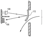
Fig. 72 is a schematic diagram illustrating light-based analysis of particle size.
FIG. 73 is a flow chart illustrating a usage cycle with end of treatment notification.
FIG. 74 is a partial cross-sectional view of the nozzle and baffle.
Fig. 75A and 75B show the switching characteristics (switch signatures) of the "snap" sound.
Fig. 76 shows one embodiment of a package or nebulizer with a bar code.
Fig. 77 illustrates one embodiment of a nebulizer having an RFID tag and a reader.
Fig. 78 is a schematic diagram of a communication protocol.
FIG. 79 is a graph of spectral drug identification.
Fig. 80A and 80B illustrate embodiments of different flow paths.
FIG. 81 illustrates a cross-sectional view of one embodiment of a reservoir.
FIG. 82 illustrates a cross-sectional view of one embodiment of a reservoir.
FIG. 83 is a cross-sectional view of one embodiment of a nozzle and a baffle.
Fig. 84 is a force/pressure graph during a breathing cycle.
FIG. 85 is a cross-sectional view of one embodiment of a receptacle.
FIG. 86 is a cross-sectional view of one embodiment of a reservoir.
Fig. 87A-87C are cross-sectional views of various receptacle embodiments.
FIG. 88 is a cross-sectional view of one embodiment of a reservoir.
FIG. 89 is a cross-sectional view of one embodiment of a reservoir.
FIG. 90 is a cross-sectional view of one embodiment of a reservoir having conductive strips.
FIG. 91 is a cross-sectional view of one embodiment of an atomizer.
FIG. 92 is a cross-sectional view of one embodiment of a reservoir.
FIG. 93 is a schematic of one embodiment of the fluid level in the reservoir.
FIG. 94 is a cross-sectional view of one embodiment of a reservoir.
Fig. 95 is a view of a nebulizer and scale.
FIG. 96 is a side and bottom view of an embodiment of a nebulizer.
FIG. 97 is a cross-sectional view of one embodiment of a reservoir and nozzle.
FIG. 98 is a cross-sectional view of one embodiment of a reservoir.
FIG. 99 is a cross-sectional view of one embodiment of a reservoir and an absorbing wavelength.
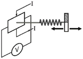
The graph 100 is a view of a conductivity arrangement for concentration determination.
Fig. 101A and 101B are cross-sectional views of the actuator and diaphragm in on and off configurations.
Fig. 102A and 102B are cross-sectional views of the actuator and diaphragm, and voltage graphs.
Fig. 103A and 103B are sectional views of an actuator with a contact switch.
Fig. 104A and 104B are sectional views of an actuator with a contact switch and a diaphragm.
Fig. 105 is a schematic diagram illustrating a smart nebulizer system.
Fig. 106 is a flow chart illustrating a smart nebulizer treatment cycle.
FIG. 107 is a diagram of a user interface with one embodiment of an output game.
Detailed Description
It should be understood that the term "plurality" as used herein refers to two or more. The term "coupled" means connected or joined, directly or indirectly, for example, through intervening members, and does not require that the joint be fixed or permanent, although it could be fixed or permanent, and could also be mechanical or electrical, including for example, wireless communication. The phrase "in fluid communication" and variations thereof means that a fluid is able to pass between components, either directly or indirectly, such as through one or more additional conduits or components. It is to be understood that the use of the numerical terms "first," "second," "third," etc., as used herein, does not refer to any particular sequence or order of parts. It should be understood that the terms "user" and "patient" as used herein refer to any user, including children, adolescents or adults, and/or animals.
The term "intelligence" refers to features that follow a general format with input, in which information is entered into the system, analysis, in which the system acts on or modifies information, and output, in which new information leaves the system. The phrase "performance characteristic" refers to a measurement, such as frequency or amplitude, that quantifies the operating condition of a device.
Referring now to fig. 1-2, one embodiment of an atomizer 10 is shown. The atomizer may include six discrete components (fig. 2), five of which may be assembled in a top-down manner, each component (except for the nozzle 12) sharing a common central axis. Such an arrangement may help reduce complexity when automated assembly is implemented. It can be seen that these components can also be assembled manually and incorporate features that reduce the likelihood of human error during assembly.
The components of the atomizer 10 include a bottom housing 14 having a cylindrical body. The atomizer 10 also includes a top portion, referred to as a holder 16, and an inner assembly, referred to as an inner housing 18. Also included in the atomizer 10 is a flexible member, referred to as a diaphragm 20. Also contained within the atomizer 10 is an elongated shaft-like member, referred to as the actuator 22. The last component is a tubular nozzle 12. The components of the atomizer 10 other than the diaphragm 20 may be formed from a single piece of material by an injection molding process and assembled without the use of welds or adhesives and joined together using an interference fit.
Referring to fig. 3A, the pressurized gas inlet 24 of the bottom housing 14 extends into a chamber 26 of the bottom housing 14. The external opening 28 of the pressurized gas inlet 24 is designed to be press-fit with a pressurized gas hose fitting (not shown). Within the bottom housing 14, the pressurized gas inlet 24 tapers into a nozzle having a pressurized gas bore 30 of a predetermined diameter. Preferably, the gas inlet 24 is coaxial with the cylindrical body of the bottom housing 14 and extends through the bottom wall 32 of the chamber 26. The inner housing 18 incorporates a nozzle cover 34, the nozzle cover 34 sliding over the pressurized gas inlet 24 on the bottom housing assembly 14.
The nozzle cap 34 is a tapered tubular member having openings at both ends. When positioned over the pressurized gas inlet 24, the space between the nozzle cover 34 and the pressurized gas inlet 24 creates at least one passageway 36, a radial opening created by the gap between the nozzle cover 34 and the bottom wall 32 of the bottom housing 14, an annular opening 38 defined by the outer diameter of the nozzle end of the pressurized gas inlet 24 and the inner diameter of the nozzle cover 34, the passageway 36 between the radial opening and the annular opening 38. To maintain the proper size of the annular opening 38 and the position of the nozzle cover 34 on the pressurized gas inlet 24, a triangular rib 40 may be included on the inner surface of the nozzle cover 34 and designed to cooperate with a ledge 42 formed near the top end of the pressurized gas inlet 24 to concentrically locate the nozzle cover 34 and maintain a passage opening 44 between the lower edge of the nozzle cover 34 and the bottom wall 32 of the bottom housing 14.
The lower chamber of the bottom housing 14 preferably serves as a reservoir 46 and holds a fluid for aerosolization, such as a solution containing a medicament. In one embodiment, the lower wall of the bottom housing 14 slopes downward to the bottom of the pressurized gas nozzle such that gravity pushes the fluid toward the opening 44 of the passageway 36 into the reservoir 46. As shown in fig. 3A, the walls of the reservoir may be disposed at an angle of approximately 45 degrees to the central axis of the nebulizer, although other wall angles may be used to reduce the remaining medicament volume at the end of the treatment. The bottom housing 14 may be constructed of a transparent plastic material to allow the patient and medical personnel to monitor the level of medicament in the nebulizer 10.
Referring to fig. 3A and 3B, the passageway 36 formed between the pressurized gas inlet 24 and the nozzle cover 34 directs fluid from the reservoir 46 through the opening 44 to the passageway 36 and the annular bore 38. In this configuration, the flow of fluid through the passageway 36 and the flow of pressurized gas through the pressurized gas inlet 24 are substantially parallel. The initial portion of the passageway 36 through which the fluid (e.g., liquid) flows is an annular or cylindrical path, which may not be vertically split. Ribs on the nozzle cover 34 of the inner casing 18 maintain concentricity and height of the nozzle cover 34 relative to the pressurized gas inlet 24, the ribs may divide the passageway 36 into three (3) separate channels near the top end of the nozzle cover 34, however, the separate channels merge and become undivided after passing the ribs before the pressurized gas orifice 30. In addition to the mass output of the nebulizer, the characteristics of the aerosol produced in the nebulizer 10 can be changed by changing the size and number of these channels near the ends of the passages 36, as well as by extending the channels to the surface of the pressurized gas orifice 30. Other passageway sizes and arrangements may be implemented to achieve the desired aerosol size and density during aerosolization. The pressurized gas bore 30 is preferably circular and concentrically aligned within an annular bore 38 communicating with the passageway 36.
The top end of the nozzle cover 34 and the top end of the pressurized gas inlet 24 may be flat surfaces. In one embodiment, the pressurized gas bore 30 lies in the plane of the annular bore 38. Alternatively, the plane of the gas holes 30 may be parallel to and offset from the plane of the nozzle cap tip. The relative heights (offsets) of the pressurized gas inlet 24 and the top end of the nozzle cap 34 may be varied to achieve desired atomization characteristics.
At the end of bottom housing 14 opposite pressurized gas inlet 24, inner housing 18 is removably attached to the cylindrical wall of bottom housing 14 using three (3) equally spaced apart ribs on bottom housing 14 and inner housing 18, under which inner housing 18 may be loosely rotated to friction fit bottom housing 14. The rotational orientation of inner housing 18 relative to bottom housing 14 may be controlled by tabs incorporated into inner housing 18 and corresponding flat surfaces on bottom housing 14 that prevent rotational movement of inner housing 18 when the inner housing is properly positioned. The ramp profile in bottom housing 14 ensures that the rib on inner housing 18 moves under the rib on bottom housing 14 because the tab follows the ramp profile. Although this example utilizes three (3) equally spaced ribs around the outer surfaces of bottom housing 14 and inner housing 18, in other embodiments any number of these thread features may be used to the same effect. When assembled, the outer surface of the inner housing 18 forms an interference fit with the inner surface of the bottom housing 14 to ensure that air and aerosol do not leak between the two components and into the surrounding environment.
The outer flange of retainer 16 contains four (4) cutouts 50, which cutouts 50 snap-fit with corresponding male extrusions 52 on the outer surface of inner housing 18 to assemble retainer 16 to inner housing 18. Two (2) textured flats 54 are included on the outer surface of retainer 16, which break the circular profile of the outer flange, which facilitates assembly of inner casing 18 to bottom casing 14 because textured flats 54 mate with corresponding flats 56 on the outer surface of inner casing 18. This facilitates implementation of automated assembly because the flats 54, 56 provide features to be grasped and oriented with a vision system for the robotic assembly system and reduce the likelihood of human error in assembly. Flats 54, 56 on inner housing 18 and holder 16 also allow these components to be bowl fed (bowl fed) to automated assembly. Retainer 16 is designed such that retainer 16 can be assembled to inner housing 18 in any of the possible configurations that allow the flats on inner housing 18 and bottom housing 14 to be parallel to each other when assembled, because this feature of retainer 16 is symmetrical. The flats 54, 56 also help to maintain the rotational orientation of the retainer 16 relative to the inner housing 18 after assembly.
Referring to fig. 2, 3A and 3B, the diaphragm 20 and retainer 16 are coaxially assembled and mounted to each other by an interference fit between the actuator 22 latching feature of the diaphragm 20 and the receiving geometry of the actuator 22. In this configuration, the actuator 22 may be assembled with the diaphragm 20 by inserting the actuator into the inner circular opening of the diaphragm 20 for a grommet-type connection. The triangular ridge 58 around the surface of the interior opening 60 of the diaphragm 20 mates with a complementary receiving triangular groove 62 on the latching surface of the diaphragm 20. In this form of latching feature, the actuator 22 incorporates two (2) curved surfaces of substantially equal diameter on the inner surface of the diaphragm 20.
When pushed through, the ridges slide into receiving grooves on the actuator 22 and weakly hold the diaphragm 20 in place relative to the actuator 22. The amount of interference between the actuator 22 and the diaphragm 20 is an important factor in the design, as excessive force can cause the diaphragm 20 to deform, affecting the flow characteristics of the valve. The assembly of the diaphragm 20 and actuator 22 does not require rotational orientation. When the diaphragm 20 is assembled to the actuator 22, there is only a top-down orientation. Although only two (2) contact surfaces 66 located at the ends of the support arms 64 extending from the central axis of the actuator 22, 180 ° apart about the common axis of the diaphragm 20 and actuator 22, are used to stabilize the diaphragm 20, any number of such features may be used in various mating geometries, although they are preferably positioned equidistantly about the actuator 22 to ensure that the diaphragm 20 is not deformed.
The diaphragm 20 and actuator 22 assembly are coaxially and slidably positioned within the atomizer within the cavity formed by the inner housing 18, with the coaxial body of the actuator 22 piston extending into the inner housing 18 along the longitudinal axis of the atomizer and through the coaxial opening in the body of the retainer 16. The closed lower feature of the actuator 22 projecting into the cavity of the inner housing 18 defines a diverter 68 for diverting the flow of pressurized gas exiting the pressurized gas bore 30. In one embodiment, diverter 68 has a flat circular surface with a predetermined area. The surface is also preferably aligned parallel to the top end of the pressurized gas inlet 24 and perpendicular to the direction of flow of pressurized gas through the pressurized gas orifice 30. The concentric alignment of the diverter 68 with respect to the pressurized gas bore 30 is aided by a downwardly angled flange 70, which flange 70 is connected to the main actuator body by two arm projections 72. The downwardly inclined flange 70 serves as a guide and slides along the outer surface of the tapered end of the nozzle cap 34. In addition to the tapered end of the nozzle cap 34, the downwardly sloping flange 70 may be a short tapered tubular feature having openings at both ends to allow pressurized gas to pass unimpeded through its center. The flange 70 also helps to set the predetermined distance 'h' between the diverter surface and the pressurized gas bore surface when the bottom of the flange 70 will contact a corresponding shoulder on the nozzle cover 34. Mouthpiece 12 is a tubular member with an oblong opening for patient breathing at one end and a cylindrical opening at the other end, which may be a 22 mm ISO standard fitting that is press fit into a corresponding cylindrical tube extending from bottom housing 14, perpendicular to the assembly axis of all other components.
With reference to the embodiment of fig. 1 to 3B, the operation of the atomizer will now be explained. During operation, pressurized gas supplied from the gas source to the pressurized gas inlet 24 continues to enter the atomizer 10 through the pressurized gas orifice 10. During operation, the actuator 22 may be in two main positions, involving two states of the nebulizer. In the first position, the diverter 68 is spaced a sufficient distance from the top of the pressurized gas bore 30 so that atomization is not initiated. The second position occurs during inhalation (and is in a continuous aerosolization mode, when this mode is set manually) and is achieved when the actuator 22 is moved downwardly relative to the remainder of the nebulizer such that the diverter 68 is moved a predetermined distance 'h' from the nozzle holes, which is suitable for aerosolizing the fluid within the reservoir 46. The pressurized gas, which may be oxygen or any other breathable gas, that continues to flow from the gas bore 30 is now deflected radially outward from the gas bore in a 360 degree pattern by the diverter 68. The gas fans out at high velocity over the annular orifice 38, creating a low pressure region over the annular orifice. The low pressure region, in conjunction with the capillary effect, draws liquid from the reservoir 46 into the pressurized gas stream through the passageway 36. The liquid is aerosolized and drawn through the nozzle 12 from the air outlet 84 in the bottom housing 14.
To enhance the ability of the atomizer 10 to eliminate non-optimally sized particles, the outer surface of the inner housing 18 may include an extension 86, the extension 86 extending to the inner surface of the bottom housing 14 and at least partially surrounding the outer circumference of the inner housing. The extension 86 serves to intercept the oversized particles entrained in the airflow and condense on the lower surface of the extension 86 before falling back into the receptacle 46. This also helps to reduce the amount of oversize particles that are inhaled through the mouthpiece. The extension may also ensure that ambient air drawn into the nebulizer takes a more circuitous route through the aerosol before exiting the nebulizer. This may help to limit particle density and reduce the chance of particle growth from accidental particle collisions. As described above, the actuator needs to move from an up/off (non-fogging) position to a down/on (fogging) position to cause fogging to occur. Inhalation of ambient air into the nebulizer via the mouthpiece 12, exhalation out through the nebulizer into the ambient atmosphere and resistance to such flow are important factors that must be controlled to minimize the work that the patient needs to do during the treatment.
A biasing element 78 integrated into the diaphragm 20 assists the actuator 22 in movement and is configured to ensure that aerosolization occurs on inhalation when in the breath actuation mode and remains closed when not inhaling to reduce the risk of release of the medicament into the surrounding environment. Minimizing the inspiratory flow required to move the actuator 22 is desirable because reducing the flow required for actuation means that aerosolization of the medicament can begin earlier in the inspiratory process and stop closer to the end of expiration, thereby generating more aerosol per breath and maximizing the medicament output. In the diaphragm 20 of fig. 1-3B, the exhalation valve 82 is incorporated into the upwardly angled circumferential valve of the diaphragm and acts as a one-way pressure relief valve.
The inspiratory flow passes through a centrally open inspiratory valve 80. In this configuration, the inhalation valve 80 uses a circular ring valve design. As previously mentioned, the use of a suction valve 80 sealed to the actuator 22 results in assembly that does not require a rotational orientation between the actuator 22 and the diaphragm 20, only a vertical orientation needs to be considered. The diaphragm 20 is pinned in place between an annular extrusion 88 (also referred to herein as an exhalation skirt) on the retainer 16 and a sealing surface 90 on the inner housing 18. This diaphragm retention technique helps maintain a constant resting position of the diaphragm 20, positions the diaphragm 20 concentrically within the nebulizer 10, separates the movement of the biasing element 78 from the circumferential exhalation valve 82, and isolates the exhalation flow path and the inhalation flow path. Upon inhalation, the exhalation flange contacts a sealing surface incorporated into the inner housing 18 and the pathway is blocked. When sufficient negative pressure is reached, the annular suction valve 80 is pulled away from the sealing surface 98 of the actuator 22 and air can flow around the sealing surface 98, through the path taken by the annular suction valve 80, and into the main chamber of the nebulizer 10. Openings 94 in the retainer 16 and openings 96 in the inner housing 18 allow air to move from the main chamber of the atomizer and out of the atomizer 10.
With reference to fig. 3A and 3B, the inhalation and exhalation flow paths within the nebulizer 10 will now be described. Prior to patient inhalation, there is an upward force acting on the actuator 22 caused by pressurized gas entering the primary chamber through the pressurized gas orifice 30 and striking the diverter 68. This upward force lifts the actuator 22 to its uppermost position, keeping the position of the diverter 68 away from the pressurized gas orifice 30 and thus in the non-atomizing position. The spring nature of the biasing element 78 on the diaphragm 20 also helps to maintain the actuator's uppermost position, with the biasing element 78 biasing the actuator 22 upwardly and away from the pressurized gas orifice 30. Pressurized gas entering the nebulizer also creates a positive pressure within the nebulizer 10, pressing the inhalation valve against the sealing surface of the actuator.
Upon inhalation, the biasing element 78 of the diaphragm 20 flips inwardly in response to negative pressure from within the nebulizer 10 acting on the lower surface of the diaphragm. This lowers the position of the actuator 22, bringing the diverter 68 closer to the pressurized gas bore 30 until the actuator 22 reaches the aerosolizing position, whereby the diverter 68 diverts the flow of pressurized gas. The negative pressure inside the nebulizer also opens the inhalation valve on the diaphragm, allowing atmospheric air to be drawn into the device to improve the delivery of fine particulate matter and maintain low inhalation resistance, thereby minimizing the work that the patient needs to perform during inhalation. Atmospheric air is drawn into the atomizer through an opening 94 integrated in the holder.
Fig. 3A shows the airflow paths of the incoming air, the supplied air and the aerosol upon inhalation. The negative pressure generated inside the device during inhalation also ensures that the outer circumferential exhalation valve 82 on the diaphragm 20 seals against the inner surface of the inner housing 18, preventing the inspiratory airflow from entering the exhalation path. Figure 3B illustrates the airflow paths of exhaled air and supplied air during exhalation.
Upon exhalation, the exhaled air moves through the nebulizer 10 and exits through the rear of the nebulizer, away from the patient, to ensure that no medicament is deposited on the patient's face or eyes. In one embodiment, two (2) rectangular windows on the back and top of the inner housing 18 are used to allow exhaled air to exit the nebulizer 10, however, other variations in vent shape and size settings are also contemplated. Vents in the inner housing 18 allow supplied and exhaled air to exit the main chamber 26 of the nebulizer 10 and move under the circumferential exhalation valve 82. Exhaled air is prevented from exiting top window 94 of retainer 16 because exhalation skirt 88 pins diaphragm 20 to inner housing 18, isolating exhalation valve 82 from inhalation valve 80. The airflow is channeled around holder 16 between expiratory skirt 88 and inner housing 18 and exits the rear of atomizer 10 through a vent 96 incorporated into inner housing 18. The positive pressure generated within the atomizer seals the inhalation valve 80 against the sealing surface 98 of the actuator 22 and prevents air from flowing out of the top window 94 of the holder 18.
Although the nebulizer 10 is preferably operated by breath actuation, the nebulizer 10 may be manually actuated. The nebulizer 10 may include a manual actuation member connected to, integral with, or contactable with the actuator piston and extending out of an upper portion of the housing through an air inlet or other opening. The manual actuation member may be integrally formed with the actuator piston. The actuating member allows a caregiver or a patient to manually move the actuator piston, thereby moving the nozzle cap such that nebulization of the nebulizer begins. Although the manually actuatable atomizer may include a diverter integrally formed with the cap, any of the other diverter or nozzle configurations disclosed herein or their equivalents may also be used.
Referring to fig. 4-6, block and schematic diagrams illustrate the operation of the apparatus. One exemplary breath-actuated nebulizer (BAN) device is the AEROECLIPSE BAN device available from Trudell International Medical, London. Various features of BAN are disclosed in U.S. patent application No.15/644,427 filed on 7/2017, U.S. patent No.9,364,618 issued on 6/2016 and 14/2013/0247903, all of which are entitled Nebulizer Apparatus and Method (Nebulizer Apparatus and Method) and assigned to the assignee of the present application, the Trudell International medicine, the entire disclosure of which is hereby incorporated herein by reference in its entirety. Various parts of the device, including the mechanical parts, may be made of plastic materials, including but not limited to polypropylene. The biasing element may be made of, for example, but not limited to, a flexible material such as silicone.
The term "input" refers to any information entered into the smart nebulizer system, which may be in the form of raw data from sensors, commands to initiate a process, or personal data entered by a user. For example, the input may be a signal from one or more sensors. For example, a pressure sensor generates an electrical signal based on the pressure in the system. The pressure sensor may be used to calculate any of the performance characteristics described above, as well as to evaluate the user's skill. The sensor assembly may include a pressure sensor placed on a Printed Circuit Board (PCB) and a bluetooth low energy (BTLE) module, microprocessor and battery, and may communicate, e.g., via bluetooth, with a computing device of a user (patient, caregiver and/or other authorized user), e.g., a mobile device including a smartphone or tablet, etc. A single pressure sensor may provide all the measurement requirements. The pressure sensor may be a differential, absolute or gauge type sensor. The sensor assembly may be incorporated into the atomizer device, for example, using a cover disposed over the assembly.
Patients/users, care providers, doctors, insurance companies benefit from the various features of intelligent nebulizers (whether BAN or continuous devices). For example, but not limiting of, the nebulizer may be linked to a mobile device, such as a personal digital assistant, tablet, or smartphone, via bluetooth, such as via an application. Various information that may be stored and/or transmitted include measured flow and breathing patterns, such as counted breaths, inspiratory time, end of treatment signals, records of when (time and date) the device was used, signals of correct inspiratory flow, activation detection, agent identification, agent concentration, particle size measurement, air supply pressure, nozzle flow, and determination of fill and residual volumes.
For faster, more accurate processing of sensor data generated within the smart nebulizer, the data may be wirelessly transmitted to a smart phone, local computing device, and/or remote computing device to interpret and act on the raw sensor data. The smart phone may display graphics or instructions to the user and implement processing software to interpret and act on the raw data. The smartphone may include software that filters and processes the raw sensor data and outputs the relevant state information contained in the raw sensor data to a display on the smartphone. The smart phone or other local computing device may alternatively use its local resources to contact a remote database or server to retrieve processing instructions or forward raw sensor data for remote processing and interpretation, and receive back processed and interpreted sensor data from the remote server for display to the user or to a caregiver with the user of the smart nebulizer.
In addition to simply presenting data, statistics, or instructions on a display of a smart phone or other local computer in the vicinity of the smart nebulizer, active operations associated with the smart nebulizer may be actively managed and controlled. For example, if a smartphone or other local computer in the vicinity of the smart nebulizer determines that the sensor data indicates that the treatment has ended, the smartphone or other local computing device may communicate directly with a pressurized gas line relay associated with the gas supply of the smart nebulizer to turn off the gas supply. Other variations are also contemplated, for example a remote server in communication with a smart phone or directly with the smart nebulizer via a communication network may decide to turn off the pressurized gas supply of the smart nebulizer when determining the end-of-treatment status.
In other embodiments, real-time data collected in the smart nebulizer and relayed to the remote server via the smart phone may trigger the remote server to track and notify the doctor or supervising caregiver about a problem with a particular nebulization session or pattern of development over time based on past nebulization sessions for a particular user. Based on data from one or more sensors in the smart nebulizer, the remote server may generate an alert to send to the user's doctor or other caregiver via text, email, or other electronic communication medium.
Referring to fig. 105, one embodiment of a smart nebulizer system is shown comprising a nebulizer 10 and a controller 340, the controller 340 having a plurality of sensors (referred to as detectors in some embodiments) (shown as three 310, 320, 330 in one embodiment) providing input to the controller. The sensors 310, 320, 330 may be embodied as, or take the form of, the various sensors or detectors disclosed below. In one embodiment, sensor 310 detects the pressure and flow rate of compressed air entering the nebulizer, sensor 320 detects the generation of aerosol, e.g., activation/actuation detection, and sensor 330 detects inspiratory and expiratory flow, breathing pattern and flow rate, specific embodiments of each of these sensors are described by way of example below, but are not limited thereto. Additional sensors for agent identification, concentration identification, particle size measurement, fill/residual volume determination, and end of treatment may also be incorporated into the system, as described below. The system also includes a feedback component 350, and the feedback component 350 may include, for example, but not limited to, visual, audible, or tactile feedback components, or combinations thereof, including, for example, a display (user interface), a speaker, and a vibrating assembly.
To calculate the inhalable dose (m)respirable) The system requires input of the total mass delivered (m)total) And Respirable Fraction (RF).
Mrespirable[μg]=mtotal[μg]xRF[%]
Using a nebulizer with a consistent mass output rate [ μ g/min ] for a given flow rate allows the system to assume that the total mass (total mass) output is equal to the total inspiratory (total impedance) time times the total mass output rate times the multiplication factor k1 based on the average inspiratory flow rate. The purpose of the multiplication factor is to account for varying drug output and respirable fraction based on inspiratory flow rate.
mtotal[μg]=k1·mrate[μg/min]xk1·tinspiratory[min]
However, the output rate and respirable fraction depend on the pressure and flow rate of the compressed air. Thus, both the output rate and the respirable fraction need to be expressed in terms of input flow rate and pressure. These relationships can be empirically calculated and classified based on the type of nebulizer. For example, the output rate of one nebulizer may take the form of:
mrate=k2·Qinput+k3·Pinput=C
where k2 and k3 are multiplication coefficients, QinputIs the input flow, PinputIs the input pressure and C is the offset constant.
Referring to fig. 105, sensor 310 senses the pressure and flow rate of the compressed air source and determines the output rate and Respirable Fraction (RF) used to calculate the total output, both of which are required to calculate the respirable dose amount.
Another variable required to calculate the inhalable dose is the total time the patient/user inhales and the nebulizer generates aerosol. The total time may be determined by calculating the duration of the overlap time for which sensors 320 and 330 detect aerosol and inhalation, respectively.
More importantly, the properties of the medicament in the nebulizer system also vary. The stored medicament database provides the necessary performance characteristics for each medicament for the nebulizer. In one embodiment, the patient/user manually enters the medicament information, for example through a smart device application in wireless communication with the nebulizer system.
Smart nebulizers also provide a mechanism to improve inhalation technology through guidance and feedback. Appropriate breathing techniques, particularly inhalation, can optimize drug delivery to the lower air passage. Forceful inhalation can cause even respirable particles to impinge in the upper air passage. Real-time feedback of inspiratory flow rate allows the smart nebulizer to provide breathing guidance that guides the user/patient's breathing cycle to ensure that they receive the desired dose of medicament.
For example, as shown in fig. 107, feedback, such as a visual display, may be configured as a game. In one embodiment, the bird 380 represents an intake flow rate that must pass through the pipe 382 without exceeding the limits (upper and lower) 384, 386.
Referring to fig. 106, a smart nebulizer flow diagram is shown. Once the system detects that treatment has begun, such as by sensing activation/actuation detection, flow from one or more sensors, or by pressing a start or on button, inputs from sensors 310, 320, 330 or other sensors disclosed below are monitored and data is captured. If inspiration ceases for a predetermined period of time, the system will time out and return to a standby state. If inhalation is detected but the input compressed air flow is incorrect, an error will occur. If inhalation is detected and the input air-air flow is correct but the nebulizer is not generating aerosol, the system will indicate the end of the treatment, calculate the inhalable dose and record the treatment data.
If inhalation is detected, the input air flow is correct, and aerosol is being generated, the system will provide real-time feedback via a feedback device about the user's inhalation flow rate and/or end of treatment to improve the technique. This feedback may take several forms, including visual (see, e.g., fig. 107), audible, and tactile. The feedback may provide a visual interface, audible or vibratory warning if the inspiratory flow rate is above or below a certain range. The feedback device may also provide a visual, audible or vibratory feedback indication that the treatment has ended. In response to this feedback, the user/patient is able to control/adjust their inspiratory flow rate and maintain that flow rate within an acceptable range, thereby maximizing their inhalable dose.
When the nebulizer system determines that the user has stopped using the nebulizer, the nebulizer system stores the therapy data locally, or sends the data to a separate on-device memory. The user or healthcare provider can view the data at a later time/date to track treatment compliance. The various features and their corresponding specifications as well as the values added to the atomizer system are listed in table 1.
Table 1: characteristics, technical requirements and added values


Enabling detection
To enable the system to track the dose delivered to the patient and determine when the treatment is over, the nebulizer system identifies when the device is active and when aerosol is generated. Knowing the duration of activation, in combination with the known performance characteristics of the nebulizer, the delivered dose can be tracked over time and the end of treatment calculated. In BAN devices, aerosol is generated when an actuator moves from an off position to an on position, and is drawn into a liquid channel and impacts a main baffle to generate aerosol. In some BAN devices, e.g., AEROECLIPSE nebulizers, a manual override button may be manually depressed to generate aerosol, or a mode selector dial may be actuated to position or configure the nebulizer in a continuous mode, wherein aerosol is continuously generated. Advantageously, but not necessarily, the smart nebulizer system is able to distinguish a BAN device or mode from a continuous delivery device or mode, as each of these situations affects the dose delivered to the patient. Movement of the actuator, audible cues, pressure characteristics, deliverability through aerosol flow, temperature and humidity changes in the presence of aerosol, capacitance, and inductance may all be used to (but are not limited to) determine when the nebulizer is activated and deactivated.
Sound-based solution, sensor in device
Referring to fig. 14-16, in a sound-based approach, the microphone(s) 102, 104 are used to "listen" for audible prompts indicating that an occurrence has occurred and that an aerosol is being generated is enabled. Many time and frequency domain methods are available for analyzing the signal provided by the microphone. The sound-based approach has the additional advantage of being able to distinguish when the nebulizer is not running (e.g., when the patient is practicing breathing techniques prior to filling the medicament bowl).
There is an audible difference between a device that is running empty and a device that is aerosolizing a fluid. Further, the microphone may be used to listen for a crack, which is an indication that the treatment has been completed. Before actuation, compressed air flows through the device. Upon actuation, liquid is drawn up the liquid path and strikes the flapper/diverter, producing an audible indication that actuation has occurred. The second microphone may be used to measure background signals and noise levels. Over time, noise or sound levels may be recorded. The microphone may also record deactivation.
In all sound-based schemes, it should be understood that the role of the microphones 102, 104 may not be limited to listening activation and deactivation, but may also be used to record background noise and eliminate it from within the system to help determine which signals indicate that activation has occurred. One example of this is an algorithm used in many noise canceling headphones, where an external microphone provides a reference noise signal and the system will add the same magnitude but inverted signal as destructive interference to the signal from inside the system.
External microphone
In one embodiment of the smart nebulizer system, the external microphone 102 is used to "listen" to the nebulizer. In this application, the microphone may be a separate component from the nebulizer itself, or may be the microphone of a telephone placed near the patient for recording sounds that occur during the treatment and displaying information to the patient using an app-based interface.
Light-based method
Light transmission actuator
Referring to fig. 26, in the light transmission enabled detection setting, the light detector 106 is positioned opposite the light source 108 with an air gap therebetween. In one embodiment, when the opaque actuator 22 is in the off position, the gap between the light source and the detector is unobstructed. Movement of the actuator 22 breaks the air gap between the light source and the sensor and changes the output of the light detector, indicating that the actuator has traveled sufficiently to generate aerosol. In another embodiment, an air gap between the light source and the light detector is blocked by the actuator in the off position. When the actuator moves to the on position, the gap is no longer blocked and the signal from the sensor changes. This is not limited to the visible spectrum of light. In one embodiment, infrared light is used so that it is not visible to the patient.
Light transmission aerosol
With reference to fig. 27A and 27B, as previously described, in the light transmission method, there is an air gap between the light source 108 and the detector 106, and a change in the signal from the light sensor indicates that activation has occurred. In aerosol-based triggers, the light source and sensor are positioned such that the air gap between them is in the aerosol or flow path 112, e.g. in the nozzle 12 or chamber 14, and the generation of aerosol will disturb the light due to scattering of aerosol particles. This will reduce the light detected by the sensor, indicating that activation has occurred. This is not limited to the visible spectrum of light and multiple wavelengths may be used. In one embodiment, infrared light is used so that it is not visible to the patient.
Light reflectivity
Referring to fig. 28A and 28B, in the light reflectance embodiment, the light sensor 110 and the light source 108 are positioned along the aerosol pathway 112. These components are isolated from each other and placed adjacent to each other such that when the nebulizer is not activated and no aerosol is generated, the sensor detects limited light due to the limited reflectivity of the opposite face of the device. In the presence of aerosol, the reflection increases due to the immediately adjacent light source and sensor, which produces a measurable difference in the intensity of light detected by the sensor. This is not limited to the visible spectrum of light and multiple wavelengths may be used. In one embodiment, infrared light is used so that it is not visible to the patient.
Color reflection
Referring also to fig. 28A and 28A, a white light source 108 is located near a detector 110 capable of identifying the color spectrum of detected light. The component is placed in the aerosol pathway such that, upon activation, aerosol is drawn in front of the component such that the presence of aerosol particles causes light to be reflected back at the sensor. In the presence of an aerosol, the aerosol will absorb light of a particular wavelength, thereby changing the wavelength that is freely transmitted back to the sensor. The change in wavelength detected by the sensor indicates the presence of aerosol and can identify the medicament being aerosolized and its concentration.
Acceleration
Referring to fig. 17 and 18, in one embodiment of a breath-actuated nebulizer, the actuator 22 moves between the off position and the on position in response to an inhalation sufficient to overcome the positive pressure within the device. An accelerometer 116 placed within the actuator 22 or on the actuator 22 may be used to measure the movement of the actuator and its duration of acceleration. The area under the generated acceleration-time curve can then be used to determine the change in velocity and total displacement of the actuator. Determination of enablement is not limited to calculating displacement of the actuator, and other algorithms may be used to accomplish the same task, such as acceleration upon inhalation and sudden deceleration as the actuator bottoms out on the nozzle cap. To improve the accuracy of the accelerometer-based activation detection method, the second accelerometer 118 may be used as a baseline or frame of reference for actuator movement. The second accelerometer will be placed in a portion of the nebulizer that is stationary relative to the rest of the device and does not move in response to inspiratory and expiratory flow (e.g., placed within the mouthpiece 12, on the holder 16, top, bottom, etc.). By doing so, motion artifacts caused by movement of the patient holding the device will not trigger a "false positive" enable detection, since both accelerometers should register similar accelerations, and the difference between them will be about zero. Because the accelerometers 116, 118 are placed in separate components, the processing unit is ideally together with a stationary accelerometer, and wired or wireless communication systems can interface between the devices. In a wired embodiment, a single power supply may be used, while a wireless system embodiment may require multiple power supplies for the sensor.
Pressure of
Absolute pressure
Referring to fig. 10-12, breath-actuated nebulizer 10 is configured with a component 120 that responds to changes in pressure within the device caused by patient inhalation and exhalation. When connected to a compressor or positive pressure air supply, the positive pressure within the apparatus pushes the biasing element/diaphragm 20 upward and holds the actuator in the off position. When the patient inhales through the device, causing the pressure within the device to become sufficiently negative to pull the actuator to the on position, an aerosol is generated. A pressure sensor 120 placed within the device, for example within the flow path 112 of the nozzle 12, may measure the pressure relative to atmospheric conditions (using sensor 122) and identify when activation has occurred based on known pressure characteristics of the nebulizer upon inhalation. As shown in fig. 10, a graph of pressure and flow profiles is shown in which actuation is determined based on measured pressure. The second pressure sensor 122 may be mounted external to the device, for example on the holder or nozzle, to provide a reference data point for atmospheric pressure. A simple threshold analysis may be used to compare the current pressure reading to the minimum pressure required to activate the device.
The pressure sensor may provide information for determining the breathing pattern and monitoring thereof. When connected to the nozzle, the sensor(s) 120, 122 can be removed with the nozzle so that the rest of the device can be cleaned. For example, as shown in fig. 12, the sensors 120, 122 may be mounted with a printed circuit board 124, the printed circuit board 124 being located at the top or bottom of the nozzle in a position that does not disrupt the oral interface with the user.
Another approach is to analyze the pressure distribution within the atomizer. The pressure profile of the system during the breathing cycle is characteristic of the nebulizer apparatus and is responsive to the movement of the inhalation and exhalation valves. Using this known profile and for the region where the signal has been emitted to activate, the signal from the pressure sensor 120 within the nebulizer system can be compared in the time and frequency domains with the target signal. This includes, but is not limited to, thresholding, autocorrelation, root mean square minimization, and spectral coherence. Multiple analysis techniques can be used together to improve the accuracy of the algorithm.
Strain gauge
Referring to fig. 7-9, in one embodiment of a breath-actuated nebulizer, a diaphragm 20 reacts to pressure changes within the device to move the actuator from an off position to an on position. Thus, as the actuator 22 moves over the nozzle cap 34 and bottoms out, the diaphragm 20 experiences minimal strain. A strain gauge 128 may be applied to a flexible biasing element of the nebulizer, the resistance of the strain gauge varying in response to changes in pressure within the nebulizer. One embodiment of such a device would involve printing a circuit on the surface of the membrane 20. When strained, the circuit path becomes elongated and narrowed, resulting in higher resistance. Conversely, when compressed, the circuit becomes shorter and wider, thereby reducing resistance. Another embodiment of such a system may have a separate flexible sensor/strain gauge 130 whose movement is driven by the movement of the diaphragm 20 or actuator 22, performing the same function as a strain gauge printed on the surface of the diaphragm. A simple threshold algorithm is required to determine when sufficient strain is present on the diaphragm to move the actuator to the on position. The amount of strain experienced by the meter is related to the pressure experienced within the apparatus and the flow rate generated by the user. In addition, the initial strain experienced by the diaphragm is indicative of the air supply pressure (compressor and center wall air) and can be used to calculate the dose delivered.
Physical switch
Single Pole Single Throw (SPST) switch
Referring to fig. 103A-104B, in the SPST switch embodiment, a moving element in the nebulizer, such as the actuator 22 or diaphragm 20, is used to close or open the switch. In the normally "off" switch embodiment, the actuator 22 and the cap seat of the nozzle cover 34 form a single pole, single throw switch 132. The power supply is connected to a discrete conductive path in the region of the cap seat on the nozzle cap. The bottom surface 134 of the actuator boot contains an electrically conductive path that bridges a discontinuity 136 on the nozzle cover, completing the circuit and signaling that activation has occurred. When the nebulizer is deactivated, the circuit becomes discontinuous. The microcontroller is used for monitoring the state of the switch.
As shown in fig. 104A and 104B, in a normally "on" switch embodiment, the interior surface 138 of the dial contains conductive paths that extend down the legs of the dial to where they meet the diaphragm. Conductive paths 140 are printed on the surface of the diaphragm 20 and the diaphragm 20 connects the contact points of the dial legs. When switching to continuous mode, the path does not continue up the ramp through which the leg moves. The circuit is continuous when the nebulizer is turned off. Upon inhalation, the diaphragm 20 moves in response to the negative pressure inside the nebulizer and opens the circuit. Conversely, when the dial 142 is rotated to the continuous mode, the legs move on the diaphragm ramp that does not contain a conductive path. The microcontroller monitors the state of the switch to determine when to activate or deactivate.
It is important to note that while both embodiments described in this section use existing components of the nebulizer to create the switch, additional components may be added to the nebulizer that respond to inspiratory flow and expiratory flow to indicate when activation and deactivation occurs. Furthermore, the method can be further extended beyond the two listed embodiments and can be extended to include any normally on or normally off switch that changes state in response to activation or deactivation of the nebulizer. The embodiments used in this section are included for illustrative purposes and show how such a method can be implemented.
Reed switch
Referring to fig. 101A and 101B, in the reed switch embodiment, the magnetic member 144 is movable relative to a stationary surface. When the magnetic element is displaced, it changes the state of the reed switch 146 from on to off or from off to on, indicating that activation or deactivation has occurred. In one embodiment, the dome of the actuator 22 is made of a magnetic material and defines a magnetic component 144, and the reed switch is incorporated into the holder 16. When the actuator has moved sufficiently, it changes the state of the reed switch, which is recognized and registered by the microcontroller 148 as being active. When the actuator 22 moves back to its initial position, the reed switch 146 moves back to its initial state and the microcontroller 148 recognizes that deactivation has occurred. It is important to note that the placement of the reed switch and the magnetic component is not limited to this one embodiment. Rather, reed switches detect activation and/or deactivation of the nebulizer, and the described embodiments are for illustration purposes only.
Inductive proximity sensor/switch
Referring to fig. 22-23B, in one embodiment, the conductive element 150 is built into a moving part of the atomizer, such as, but not limited to, the dome of the actuator 22. A corresponding coil 152 is placed around or near the path of movement of the component, such as the inner diameter of the dial. On inhalation, the moving part (actuator) 22 moves from the off position to the on position so that the conductive element 150 of the moving part is closer to the coil 152 or circuit of the stationary part of the nebulizer. High frequency current is passed through the coil 152 or loop to generate an electric field. There is a measurable change in the impedance of the coil 152 or loop when the conductive element of the moving part is close to or away from the loop. This change in impedance may signal when activation occurs. This feature and principle can be applied to any of the movable components within the atomizer.
Capacitance switch
Referring to fig. 24 and 25, capacitive switch/proximity sensor 154 may also be used to determine when activation occurs. The two parallel plates 156, 158 are positioned such that one plate is placed on a "stationary" part of the nebulizer (not moving in response to the breathing cycle) and one plate is placed on a movable part, such as an actuator or diaphragm. The capacitance between the parallel plates 156, 158 depends on the permittivity of the free space (d), the dielectric constant of the material in the gap, the overlapping area of the plates, and the distance between the plates. If the plates are located in a region where the overlap area of the plates, the permittivity of the free space and the dielectric constant of the material in the gap are fixed, the change in capacitance is due to the change in distance between the plates. In one embodiment, the two plates are separated by an air gap. One plate forms a ring around the underside of the dial/holder and the other plate forms a ring on the top surface of the diaphragm, opposite the plate on the dial/holder. In response to the inspiratory flow, the distance between the plates increases and the capacitance changes. Knowing the relationship between capacitance and distance, the distance between the actuator and the dial can be determined, thereby determining whether the actuator has moved sufficiently to generate aerosol. The air gap is preferably not located in the aerosol route, as the dielectric constant of the material in the air gap is preferably kept constant. The capacitance may be monitored with an oscillator or charge/discharge circuit, and a change in frequency indicates that aerosol production has occurred or ceased.
In another embodiment shown in fig. 25, the distance between the plates 156, 158, the permittivity of the free space and the dielectric constant of the material between the two plates remain constant and the area of overlap of the two plates varies. One plate is located in the dome of the actuator and the other plate is located in a stationary holder or dial. On inhalation, the overlapping area of the two plates increases or decreases depending on their initial positioning. As the actuator moves axially in the atomizer, the distance between the plates will remain constant, only the overlapping area will change, thus changing the capacitance. The air gap is preferably not located in the aerosol route, as the dielectric constant of the material in the air gap is preferably kept constant. The capacitance may be monitored with an oscillator or a charge/discharge circuit, and a change in frequency indicates that aerosol generation has occurred or ceased.
Hall effect
Referring to fig. 102A and 102B, a hall effect element 160 may be used to measure the activation and deactivation of the nebulizer. A hall effect element operates by measuring the voltage of the hall effect element perpendicular to the direction of current flow through the element. In the presence of a magnetic field, a voltage is induced across the element that is proportional to the field strength. In one embodiment, the hall effect sensor 160 is mounted on the holder 16, while the dome of the actuator contains the magnetic feature 144. Upon inhalation, the movement of the actuator 22 can be monitored by the microcontroller 148, with the microcontroller 148 measuring the lateral voltage of the hall effect element, as the proximity of the magnetic dome to the sensor will change the output voltage. When the voltage threshold is reached, the microcontroller may issue a signal indicating that priming has occurred because the actuator has moved sufficiently to generate aerosol. Although this embodiment describes movement of the actuator to bring the magnet closer to the hall effect sensor, embodiments in which the magnetic component moves away from the sensor on an inhalation are also suitable. Further, the placement of the hall effect sensors and magnetic features is not limited to holders and actuators, and any hall effect element may be used to measure activation and deactivation.
Force sensing baffle
Referring to fig. 83 and 84, in one embodiment, a force or pressure sensing element 162 is incorporated into baffle 165. When the actuator is in the off position, a reduced flow of air strikes the flapper as a portion of the air flow escapes through the vacuum break windows in the nozzle cover 34. When the actuator 22 is down, all air flow is directed toward the baffle 165, as the windows in the nozzle cover are blocked, and air is entrained through the bottom opening of the nozzle cover. The force is further increased when the liquid is pulled through the liquid passage and hits the baffle. This force/pressure reading may be recorded by the sensing element 162 and monitored by the control unit, increasing beyond a certain threshold indicative of aerosol formation, as shown in fig. 84, for each of airflow/actuator up, actuator down/no liquid and liquid hitting the baffle. This embodiment enables to distinguish between a device running empty and a patient practicing the proper breathing technique and aerosol generation.
Humidity
Referring to fig. 19 and 20, in one embodiment, the humidity sensor 166 is placed within the nebulizer, in the aerosol pathway 112. One possible location is within nozzle 12 because it is close to the patient. Prior to aerosol generation, compressed air from a central air supply or compressor is moving past the sensor. On activation, the aerosol generated within the device is collected by the compressed and introduced air and flows along the inspiratory pathway to the patient. The air is saturated with droplets of aerosolized medicament and exhibits an increase in humidity as it flows past the sensor. When the device is deactivated, aerosol generation will stop and the compressed air flowing through the sensor and the incoming air flow will no longer be saturated with water vapour. For such embodiments, the sensor 166 is preferably calibrated prior to each treatment for the relative humidity and compressed air source of the environment in which it is used. The calibration may be performed using a second external humidity sensor. The minimum humidity change over a predefined period of time may be used to detect activation and deactivation, but many detection algorithms may be used.
Temperature of
Referring to fig. 13A-13E, in one embodiment, a temperature sensor 168 is placed within the nebulizer, in the aerosol pathway 112. The temperature sensor 168 can determine whether the equipment is being supplied with compressed air because the air flow over the temperature sensor will produce a measurable temperature reduction when compared to stagnant air. This can be used to "wake up" the device from a sleep or low power mode. When the actuator is moved to the on position and the aerosol flows along the inspiratory pathway (fig. 13B), the temperature decreases as the particles deposit on the sensor and evaporate. A further drop in this temperature indicates that priming has occurred, with a continuously decreasing temperature level indicating the duration of aerosol generation.
Deactivation occurs in two ways. The first situation is when the patient exhales through the device (fig. 13C). This creates a positive pressure within the device and the actuator moves to the off position. The temperature will rise due to the cessation of the aerosol and the passage of warm, moist air from the patient's lungs past the sensor. This indicates that activation has ceased. In the second situation (fig. 13D), the patient moves the mouth away from the mouthpiece to exhale, and no negative inspiratory flow allows the actuator to move back to the off position. As previously described, the absence of aerosol deposition and evaporation on the sensor manifests as an elevated temperature increase, and the system recognizes that deactivation has occurred.
Although the above embodiments describe the pressure sensor being placed directly in the aerosol route, the pressure sensor may also be placed elsewhere on the device and measure local temperature changes. A plurality of temperature sensors 168, 170 (see fig. 13E) may be used to measure temperature changes relative to the external environment to improve the accuracy of the system and to set a reference temperature.
Capacitance-dielectric constant of aerosol
Referring to fig. 21, assuming that the dielectric constant of the aerosol is different from that of air, a capacitive sensing method may be used to determine when activation occurs. The capacitor 154 may be formed, for example, by separating two conductive materials 156, 158 by an insulating air gap in the flow path 112 of the nozzle 12. The air gap is positioned such that, as aerosol is generated, aerosol flows through the gap. If the dielectric constant of the aerosol is different from that of air, the change in conductivity in the presence of the aerosol will result in a measurable change in capacitance. The capacitance may be monitored with an oscillator or a charge/discharge circuit, and a change in frequency indicates that aerosol generation has occurred or ceased.
Flow rate
Measuring flow through the device is not a direct method of determining when enablement has occurred, but rather actuation may be registered using known performance characteristics of the device, such as a known flow rate. Measuring flow is also important for monitoring the breathing pattern of a patient during treatment. Thus, all embodiments and methods covered in the next section "measure flow" are also applicable to determine when enablement has occurred.
It is important to note that the various embodiments and methods disclosed herein may be combined to register actuation. Indeed, a combination of any of these techniques is contemplated, as different embodiments/techniques may be linked together to improve accuracy and extend the capabilities of the nebulizer system.
Measuring flow/breathing patterns
It would be advantageous for a smart nebulizer to be able to monitor the patient's inhalation and exhalation during patient treatment. Appropriate breathing techniques, particularly inhalation, can optimize drug delivery to the lower air passage. Too great a force of inhalation may even result in the impact of respirable particles in the upper air passage. Real-time feedback of inspiratory flow rate will allow the smart nebulizer system to provide a breath guidance feature that guides the patient/user's breathing cycle to ensure that the patient/user receives the desired dose. Various electronic devices are available for measuring flow, including internal sensors that may be placed within the nebulizer, external sensors, and a separate device capable of interpreting nebulizer operating characteristics and correlating these signals with flow through the device. The breath monitoring embodiments and methods may be adaptable and capable of determining flow when used with air supplies of various pressures. The respiration monitoring embodiment is preferably robust enough to reject ambient noise and isolate the correlated signals.
Sound-based scheme
Inherent sound
Referring to fig. 29 and 30, a microphone 104 may be used to measure the inherent sound produced by the device as it flows through the device. The airflow path 112 within the nebulizer is often deliberately distorted to control aerosol particle size. This creates turbulence which must bypass complex, blunt geometries. As the flow rate increases, and the turbulence experienced increases accordingly, the inherent sound produced by the device also changes. The microphone may be placed inside the device, on the outer surface or as a separate sensor to detect the sound caused by the airflow through the nebulizer. Through experimental tests, the relationship between the detected sound and the flow velocity can be determined. Many signal processing and analysis techniques are available to correlate the microphone data with the traffic, such as simple volume thresholds to more complex frequency domain analysis techniques. The sound is not limited to a sound detectable by the human ear, and a wide frequency band may be used.
The intrinsic sound based flow measurement technique is not limited to the use of a single microphone, and multiple microphones 102, 104 may be used to improve the accuracy of the flow measurement as well as capture ambient noise.
Generated sound
Referring to fig. 31, much like the inherent sound scheme, a single microphone 104 or multiple microphones are used to detect sounds intentionally generated by the nebulizer using a particular geometry 170, the particular geometry 170 emitting sounds as the airflow passes through the particular geometry 170, much like the FLOWSIGNAL flow indicator in an AEROCHAMBER aerosol holding chamber. In one embodiment, a sound generating geometry 170, such as a reed, is placed in front of the suction window 172 of the nebulizer. Alternatively, the sound-generating geometry is moulded into the suction window itself. Upon inhalation, air is drawn through the sound generating geometry, creating a known sound. The volume change or frequency shift caused by the changing flow rate may be recognized by the acoustic sensing unit of the nebulizer system and correlated to the flow rate. Similar components may be added to the exhalation port to recognize the exhalation flow rate. The use of generated sounds to measure flow is not limited to placement in the inhalation and exhalation windows, but may be placed anywhere in the inhalation and exhalation path within the device. Different tones may be generated for each flow path to distinguish between inspiratory flow and expiratory flow. As with the natural sound method, the generated noise is not limited to the range of human hearing.
Doppler method
Referring to fig. 32, the doppler effect can be used to measure the velocity (and flow rate) of particles passing through the nebulizer. The transmitter and receiver units 174, 176 are positioned such that, in the presence of aerosol, sound generated by the transmitter is reflected back at the receiver. This may be achieved by angling the transmitter and receiver with respect to the flow path. The received sound is shifted in frequency due to the velocity of the aerosol reflecting the sound. If the particles are moving in the opposite direction to the direction of the transmitted sound, the reflected sound waves will be compressed to a greater extent and therefore at a higher frequency. The level of frequency shift may be related to the velocity of the particles. Knowing the cross-sectional area of the gas flow, the velocity can be used to calculate the flow rate. This method is suitable for bi-directional flow, except that the received sound is at a lower frequency than the transmitted wave. Notably, this method requires the presence of an aerosol to act as a reflector. Thus, the method may also be used to detect activation, but the flow rate of dry air in the nebulizer may not be determined prior to activation.
In one embodiment, the transmitting and receiving parts are placed adjacent to each other on the wall of the nozzle. The transmitter and receiver are angled such that the signal is projected at an angle along the flow path and not emitted perpendicular to the flow. This method is not limited to any one frequency range, although it is often used for ultrasonic signals.
Time of flight/transit
Referring to fig. 33, in a time-of-flight or time-of-flight flow measurement embodiment, two transmitter and receiver components 174, 176 are placed on opposite faces of a cylindrical element through which air flows. The sensors are placed at an angle θ to each flow path, with the transmitter/receiver of each component facing each other. In one embodiment, the cylindrical element will be a nozzle. Sounds are emitted by each component at opposite time intervals and the time required for the sounds to reach the opposing sensor is calculated. Knowing the time of flight between the sensors in both directions gives an average flow rate independent of the gas or particles passing through the air passage-knowing the geometry and velocity of the nebulizer allows calculation of the flow rate.
Pressure-based solutions
Pressure relative to atmosphere
Referring to fig. 34, in one embodiment, a pressure sensor 120 is placed within the device to measure the internal pressure. The sensor must be placed in the closed system formed when the patient places the mouth on the mouthpiece. This is the area where pressure changes in response to patient breathing, such as in mouthpiece 12. Upon inhalation, the internal pressure of the nebulizer is negative relative to the atmosphere and the flow is inhaled through the inhalation valve into the patient's lungs. As the flow rate increases, the air flow into the atomizer is also restricted by the inhalation valve that restricts the inhalation port, thereby creating a greater vacuum. Thus, increasing the airflow requires greater effort by the patient. Upon exhalation, the pressure within the nebulizer becomes positive and increases as the expiratory flow increases, because the size of the exhalation port and the valve covering the exhalation port limit the discharge from the device. There is a relationship between internal pressure and flow rate, although it depends somewhat on the characteristics of each valve and possible leaks in the atomizer. A second pressure sensor 124 may be included to measure atmospheric pressure and result in a more robust design that enables accurate internal pressure measurements independent of the external environment.
Venturi tube
Referring to fig. 35, the venturi effect can be used to measure flow by creating a venturi tube 180 within the atomizer, the venturi tube 180 forcing a pressure drop in a region having a known geometry. A cylindrical tube is produced with a smooth transition from one diameter to another having a known cross-sectional area. Assuming that the flow is steady-state and laminar, and that the compression of the gas is minimal, conservation of mass requires that the velocity must be changed to maintain the same flow rate. This produces a local pressure drop according to bernoulli's equation. The pressure drop can be measured and the flow rate calculated.
The venturi geometry is incorporated into a portion of the atomizer, such as nozzle 12 shown in fig. 36, to produce a measurable pressure drop, which is recorded as a pressure differential. A disadvantage of this approach is that the narrowing of the nozzle accelerates the aerosols and provides them with greater momentum, potentially increasing the impact on the upper air passage.
Alternatively, as shown in FIG. 37, the bypass venturi 182 is formed outside of the primary airflow path through which a portion of the airflow flows. The flow rate through this portion of the nozzle is related to the air flow rate through the body. The nozzle includes a cylindrical basic geometry that transitions to a smaller diameter and may create a measurable localized pressure drop for this embodiment.
Pitot static tube
Referring to fig. 38, in pitot-static tube embodiments, a generally cylindrical geometry 184 with one closed end is used to create stagnation areas in the flow path. The open end of the cylindrical tube faces the incoming flow. The pair of tubes 184 may face in opposite directions. A pressure sensor 186 is placed within the tube, typically on the inside of the closure face. In the presence of a gas flow, a portion of the flow enters the tube and stagnates, building up pressure within the tube. The greater the flow rate, the greater the pressure in the tube, as the air will experience more deceleration and exert more force on the sensor. This pressure profile can be characterized by testing and the relationship between the pressure in the pitot-static tube and the flow rate produced. A second sensor may also be placed to measure atmospheric pressure for reference and calibration purposes.
In one embodiment, two pitot static tubes may be placed in the nozzle with the tubes facing in opposite flow directions. On inhalation, one pitot tube will experience a pressure rise while the other will experience no pressure change or a small pressure drop. This embodiment has the advantage of not only measuring the flow rate, but also the direction of flow in the atomizer.
Flow-limiting hole
Referring to fig. 39 and 40, similar to a venturi tube, the restricted orifice method of measuring flow uses the change in cross-sectional area to force a measurable pressure drop. Unlike the venturi embodiment, the flow restriction orifice 188 is an abrupt change in cross-sectional area, which allows for a greater change in pressure. However, the restrictive orifice may cause the aerosol to accelerate faster and interfere with the flow path. Furthermore, a sudden change in cross-sectional area may increase the impact of the aerosol. Unlike venturi flow measurement, the restrictive orifice provides a bi-directional pressure measurement. The restrictive orifice is positioned between the patient/user 183 and any valves or leaks to measure flow into and out of the patient's lungs.
As shown in fig. 40, the user 183 has positioned the nozzle in their mouth. It should be understood that the same description applies to all other embodiments disclosed herein, meaning that these embodiments are also located in the mouth of the user during use.
Wedge flow measurement
Referring to fig. 41 and 42, although similar to the restrictor hole embodiment, one side of the flow path is restricted by a triangular cross-section or wedge 190, for example within the cylindrical flow path of the nozzle 112. The cross-section creates a pressure differential below the flow restriction orifice and thus less disruption to flow. This embodiment is suitable for low reynolds number gas flows (laminar flow). As with the flow restriction orifice, this embodiment provides a bi-directional method of measuring flow. In one embodiment, the flow restriction is placed within a nozzle having a cylindrical shape, in part because flow turbulence is minimal at this point in the atomizer.
Light-based method
Reflectivity-inside
Referring to fig. 43, light source 108 and sensor 106 may be placed adjacent to each other, but separated by an opaque material so that direct light from the light source cannot reach the sensor. The source and the sensor are both directed in the same direction toward a component of the nebulizer that moves in response to the flow, and the extent to which the component moves is dependent on the flow rate. For purposes of illustration, an embodiment using an existing inhalation valve 192 and exhalation valve 194 will be described. When the patent is not breathing through the device, the valve is closed and much of the light is reflected from the valve back to the light sensor. Upon inhalation, the inhalation valve 192 curls in response to flow and some light is allowed to pass through the inhalation window while some light is still reflected back to the sensor. As the motion increases, the curl angle of the valve also increases and the light reflected back to the light sensor also decreases. The same process occurs on exhalation as exhalation valve 194 moves away from the valve seat with the flow of exhalation. A relationship between the flow rate and the intensity of light received by each light sensor can be determined. This embodiment has the advantage that the flow direction can be determined, since a reduced reflectivity of the suction valve indicates a suction flow and vice versa. The embodiments and methods are not limited to existing inhalation and exhalation valves and may be extended to any component that moves in response to flow and whose extent of movement depends on the flow rate. This embodiment and method is applicable to all wavelengths of light and all filtering methods.
Is irradiated through
Referring to fig. 45A and 45B, the light source 108 and sensor 106 are placed on opposite sides of the member 192, and the member 192 moves in response to the flow and limits the intensity of light reaching the sensor. The light source may be an ambient light source or be generated by a light source such as an LED. It is also applicable to light of all wavelengths and is not limited to the visible spectrum. As the flow rate increases, the degree of movement of the movable member increases. This allows more light to pass through the sensor. The relationship between the light intensity registered by the light sensor and the flow rate can be determined. As described with respect to the reflectance-internal embodiment, one embodiment uses existing inhalation and exhalation valves (fig. 46), with a light sensor placed opposite the valve such that movement of the valve allows light to pass through the light sensor during inhalation and exhalation.
Oscillating member
Referring to fig. 47A-47C, opaque oscillating member 200 is placed within flow path 112 with light source 108 and sensor 106 on both sides. When there is a flow, the oscillating member moves at a frequency characteristic of the flow rate. The oscillation of the member periodically blocks the path between the light source and the sensor. The frequency of such oscillations may be related to the flow rate. A vibrating element, such as a reed 200 (in one embodiment the reed 200 moves left and right (fig. 47B), or a rotating component 202 (fig. 47C), such as a windmill, may be used, however, this embodiment/method is not limited to these two oscillating components, but is applicable to any component that moves at a set frequency in the presence of flow and periodically blocks light from being sent to the sensor.
Temperature-based method
Hot wire anemometer
Referring to fig. 48, the wire 204 is electrically heated and placed within the flow path 112. When air flows through the wire 204, the wire is cooled and the resistance of the wire changes. The circuit for measuring temperature changes may be a constant current, constant voltage or pulse width modulation configuration. All methods are effective in measuring temperature changes and can be experimentally correlated with air flow. This embodiment may include any thermistor or thermocouple located inside the device.
Thin film thermal sensor
Referring to fig. 49A and 49B, the thin film sensor 206 is placed on an inner or outer surface of the device (not in the flow path), such as outside of the bottom housing 14. As the air flows in the atomizer, it cools the surface of the device and, as in the hot wire anemometer configuration, causes a measurable change in resistance in the sensor that can be monitored by the microcontroller 148, but is not so limited. This embodiment should take into account that the temperature of the nebulizer is also related to the presence of aerosol and that the response time may be slow, since heat transfer must take place in the body of the device in order to detect temperature changes by means of a thin film placed on its surface.
Strain/flexibility sensor
Deflection
Referring to FIG. 50, air flowing through the element 208 in the airflow path 112 exerts a force on the element. An increase in airflow also increases the force applied because particles experience greater deceleration upon impact, which is directly related to their applied force. By placing the flexible sensor 208 in the airflow path, the air flow rate may be calculated based on the deflection level of the flexible sensor. Experimentally, the deflection level is related to the flow rate.
This may also be applied to existing inhalation and exhalation valves that respond to inhalation and exhalation flows with deflection levels that are related to the flow into and out of the nebulizer. Strain gauges may be printed on existing valve surfaces to measure their deflection level, which may then be correlated to flow. Alternatively, the existing valve itself may be replaced with a flexible sensor that controls flow rate and direction.
The flexible sensor may be resistance based or made of piezoelectric material. In the resistance-based embodiment, the deflection of the sensor results in a change in resistance that can be monitored by the control unit using a variety of methods. In a piezoelectric embodiment, the deflection of the sensor generates a voltage proportional to the amount of deflection.
Strain on the diaphragm
Referring to fig. 51A and 51B, in one embodiment, one or more strain gauges 128 are integrated into the biasing element 20, e.g., a diaphragm, of the nebulizer to measure the strain experienced by the flexible material. The biasing element may be a spring geometry formed from a silicone diaphragm. Upon inhalation, the diaphragm 20 responds to changes in internal pressure and is pulled down to activate the actuator. As the inspiratory air flow increases, the vacuum pressure increases and the diaphragm is continually pulled down and strained even though the position of the actuator is limited by the nozzle cap. The level of strain experienced may be related to inspiratory flow rate. Upon expiration, positive pressure builds up within the device, which also strains the diaphragm and may be related to the expiratory flow rate. Use of this embodiment in conjunction with activation/deactivation detection will allow the nebulizer system to determine flow rate and flow direction.
Oscillation
Referring to fig. 52 and 53, an oscillating member 210 is placed in the air flow path 112, which will oscillate at a frequency proportional to the flow rate. The component may consist of a resistive flexible sensor that changes impedance when deflected or a piezoelectric material that generates a voltage when deflected. The frequency of the oscillation may be monitored by a control unit which may relate the frequency to the flow rate by an experimentally determined relationship.
Turbine flowmeter
Referring to fig. 54, a rotor or windmill 212 is placed within the flow path 112. The flow causes the rotor or windmill to rotate at a frequency related to the flow velocity. The rotational speed of the turbine can be measured in many ways, for example by hall effect elements to detect the opening of passing rotor blades, contact switches or light curtains. It is important to note that determining turbine speed is not limited to the methods listed herein. This method is advantageous because it does not cause a significant pressure drop. However, placing a turbine in the aerosol route may increase aerosol shock and reduce medicament output.
Displacement of
Referring to fig. 55, all methods of measuring displacement have at least two common elements: : (1) a stationary component 212 that does not respond to inspiratory and expiratory flow; and (2) a movable member 214 that moves along one axis during inspiration and expiration. Various embodiments may include a third element: (3) a connecting member connecting the stationary and movable members, such as a spring 216 (linear or non-linear), returns the movable member to a steady state position when there is no air flow by the spring 216. Upon inhalation, the air flow moves the movable member relative to the stationary member. The greater the flow velocity, the greater the displacement produced by the air flow, which experiences a significant deceleration as it strikes the movable member, thereby exerting a greater force. This configuration may allow for one or two way movement depending on the type of spring used, which would allow one configuration to be able to measure inspiratory and expiratory flow rates. As shown in fig. 61, the displacement is preferably measured in a region 228 between the user/patient and any bias in the airflow path, such as in the nozzle.
In various embodiments disclosed below, the displacement flow rate measurement technique relies on the measurement of local flow and is generally located between the oral interface and any deviation in the airflow path. Leakage and exhalation and inhalation pathways are examples of such biases. By placing the sensing unit in this area, the airflow experienced by the patient can be measured directly. The sensing element may be placed elsewhere in the nebulizer system, but no longer directly measure the flow experienced by the patient.
Hall effect
Referring to fig. 56, the hall effect sensor 212 is in a rest position and the movable member 214 is comprised of a magnetic material. The spring 216 connects the two components. Upon inhalation, the flow exerts a force on the magnetic element, bringing it closer to the hall element and producing a measurable change in the magnetic field. This variation may be related to the displacement of the magnetic component and the air flow rate. Upon expiration, the element is further away from the hall element. Although the above embodiments describe the magnetic elements moving closer on inhalation and further on exhalation, the opposite orientation will accomplish the same task.
Capacitor with a capacitor element
Referring to fig. 57, the capacitive switch/proximity sensor approach can also be used to determine the displacement of the movable component relative to the stationary component. The two parallel plates 212, 214 are positioned such that one plate 212 is placed on the "stationary" part of the nebulizer (not moving in response to the breathing cycle) and one plate 214 is placed on the movable part, the two plates being connected by a non-conductive biasing element, such as a spring 216. The capacitance between the parallel plates depends on the permittivity of the free space, the dielectric constant of the material in the gap, the overlap area of the plates, and the distance between the plates. If the plates are located in a region where the overlap area of the plates, the permittivity of the free space and the dielectric constant of the material in the gap are fixed, the change in capacitance is due to a change in the distance between the plates, which is related to the air flow. As with the hall effect embodiment, this may use a single configuration to measure inspiratory and expiratory flow, but multiple configurations may be used if more appropriate. This embodiment is preferably used when the dielectric constant of the material in the air gap is constant, so that the air gap is preferably not located in the aerosol path, or the space between the plates is shielded from the aerosol. The capacitance can be monitored with an oscillator or charge/discharge circuit and a change in frequency is indicative of the flow rate.
Inductance
Referring to fig. 58, the conductive element is built into the moving part 214 of the displacement sensor. The respective coils 212 are placed around or near the path of the component movement and are stationary relative to the rest of the atomizer system. Alternatively, the coil may be moving and the conductive element stationary. During inhalation, the moving member moves relative to the stationary member. High frequency current passes through the loop to generate an electric field. There is a measurable change in the impedance in the loop when the conductive element of the moving part is close to or away from the loop. This change in impedance is directly related to the displacement of the sensor. The displacement of the sensor is in turn related to the flow rate.
Reed switch
Referring to fig. 59 and 60, for the reed switch embodiment, the magnetic component 218 is made movable relative to the stationary surface 220 and is connected by the biasing element 216. When the magnetic element displaces, it changes the state of the series 222 of reed switches 224, the series 222 of reed switches 224 being positioned such that activation or deactivation of the switches can be correlated to the displacement of the movable element. The principle can be applied to any number of reed switches and also to the magnetic elements that activate or deactivate the switches. This displacement may be related to the flow rate.
Potentiometer
Referring to fig. 60, the movable member 226 is connected to the potentiometer such that when the movable element moves, it changes the impedance of the potentiometer. A simple wheatstone bridge circuit and microcontroller can be used to monitor the resistance. Note that impedance monitoring is not limited to this basic circuit.
Vibration/acceleration
Referring to fig. 62 and 63, similar to the sound-based approach, the tortuous flow within the nebulizer is designed to produce respirable-sized particles, creating turbulence as the airflow is forced around the irregular blunt geometry. The air flow and aerosol particles that strike these surfaces exert forces on the atomizer and cause the device to vibrate at very low amplitude, high frequency levels. This vibration can be measured by placing an accelerometer 230 on the surface of the device. This idea can be extended to one (1), two (2) and three (3) axis accelerometers. The microcontroller 148 will sample the data from the accelerometer and analyze it. This analysis can be programmed into the microcontroller or sent to an external unit with greater processing power. The signals may be analyzed by a variety of methods in the time and frequency domains to detect acceleration patterns that may be related to airflow through the device. The accelerometer may record the acceleration caused by the patient moving the device, also known as motion artifact. Typically, motion artifacts are low frequency and can be removed using a high pass filter. The vibrations caused by the airflow are expected to have higher frequencies and may be separated from motion artifacts in the frequency domain.
This embodiment may be extended to include measurement of acceleration produced by the oscillating member. Much like the previously described method of generating sound, a component may be added that oscillates at a frequency proportional to the flow rate through it. Unlike the acoustic method, the oscillating component does not produce sound, but the oscillation is transferred directly to the device or accelerometer to measure the amplitude and frequency of the vibration. The amplitude and frequency of the vibration may in turn be flow dependent.
Air supply pressure and nozzle flow
Referring to fig. 64 and 65, determining the pressure and air flow supplied to the device is important for accurate calculation of drug output and delivery rate. These two parameters cannot be separated because they both contribute to drug output rate and particle size. Wall or central air supplies used in hospitals are typically capable of delivering 50 psi. However, various nebulizers may provide instructions that instruct the user or caregiver to turn down the pressure until the flow rate is between 7 and 8L/min. The nebulizer may also be configured to work with nebulizer compressor 236, including OMBRA desktop and portable compressors of trodell International Medical corporation (Trudell Medical International). For these supply components, it may not be necessary to reduce pressure or flow because they are configured to operate at maximum performance. Nozzle flow differences between equipment operating on the same compressor are due to variations in nozzle orifice size and flash (flash). It is important to know both the pressure and the flow rate, since the particle size depends on the energy provided by the compressed air source. With the same nozzle flow but at a higher pressure, the higher pressure compressor may produce finer particles, all other factors remaining unchanged as it has more energy transferred to the liquid to increase the surface area (droplet formation).
Nozzle pressure and flow may be measured or inferred directly. Direct measurements in line with the compressed air supply and nozzle orifices may be used, or measurements may be taken elsewhere in the atomizer system in relation to the air supply pressure and flow rate.
Embodiments and methods of directly measuring pressure are preferably configured to not cause significant permanent pressure loss, especially in atomizers operated with compressors that are well below 50[ psi ] maximum operating pressure.
Direct pressure measurement
Absolute or relative to atmospheric pressure
Referring to fig. 66 and 67, as described in the pressure-based protocol-flow measurement, the pressure sensor 232 may be placed in line with the air source (e.g., tube 234) of the nebulizer and either measure the absolute pressure within the device or by adding a second sensor 236 to the atmosphere and then measuring the pressure relative to the atmosphere. The pressure sensor is not limited to being placed within the nozzle and may be placed within the conduit 234 itself.
Strain gauge
Referring to fig. 68, a strain gauge 128 placed on a flexible hose 234 for conveying a source of compressed air may be used to determine the pressure supplied to the atomizer. In one embodiment, the strain gauge is placed on a conduit for connecting the atomizer to wall air or a compressor. When the pipe is pressurized, it is placed under tension and expands. This expansion can be measured with strain gauges and communicated to the control unit through physical or wireless communication.
Direct flow measurement
Pressure of
All flow measurement techniques covered in the "measure flow-pressure based solution" section can be used as on-line flow measurement techniques, but all of these result in permanent pressure losses of varying degrees, which should be avoided. The method can also provide absolute pressure by monitoring downstream pressure sensor readings or provide pressure relative to atmosphere with the addition of a third sensor exposed to the external environment.
Sound equipment
Measuring the flow-time of flight/transit time is suitable for measuring the air flow applied to the atomizer. The sensor may be placed anywhere between the conduit attachment of the atomizer and the exit orifice.
Temperature of
Measuring flow-a temperature-based scheme is suitable for measuring the air flow applied to the atomizer. The sensor may be placed anywhere between the conduit attachment of the atomizer and the exit orifice.
Turbine wheel
Measurement flow-turbine flow meter is adapted to measure the air flow exiting the atomizer pressurized gas orifice. The sensor may be placed anywhere between the conduit attachment of the atomizer and the exit orifice, but this approach may result in permanent pressure loss.
Inferring pressure/flow measurements
Inferring pressure and flow calculations does not provide a direct measurement of pressure or flow, but can be inferred if the calculation error introduced by the combined range of pressures and flows is not statistically significant. Inferred measurements of pressure and flow cannot distinguish between pressure and flow because these parameters cannot be separated from each other without direct measurement of each quantity. Therefore, in the following method only pressure is mentioned, since it is the driving force for the flow. Flow fluctuations at constant pressure are the result of changes in the pressurized gas pore size and flash level.
Inherent sound
When pressurized air is supplied and runs empty, the atomizer emits a sound that is characteristic of the pressurized gas being expelled from the orifice. As with flow measurements using sound, sound is dependent on the flow leaving the orifice and the subsequent turbulence caused by the air following a tortuous path in the device. An increase in pressure may result in an audible increase in sound intensity and may affect the frequency content of the sound. The sound and the sound of the nebulizer may be monitored prior to treatment using a single or multiple microphones to establish the pressure/flow from the air supply. There are a variety of analysis techniques that can analyze and compare sound to a library of known sound profiles with known performance characteristics using a local control unit or a remote control unit to which data is wirelessly transmitted.
Vibration/acceleration
As with vibration/acceleration-flow measurement, an accelerometer can be used to measure the vibration of the nebulizer prior to aerosolization. These vibrations may provide an indication of the pressure/flow supplied to the nebulizer, each pressure/flow having a characteristic acceleration signature. The vibration/acceleration-flow measurement section above provides more details regarding the implementation of such embodiments and methods.
Flow-through device
All of the embodiments and methods described in the measure flow/breathing mode section can be used to measure the pressure/flow supplied to the nebulizer. The flow measurement made when the device is idle without the patient interfacing with the device is indicative of the pressure/flow supplied to the nebulizer. Through experimental testing, local measurements of pressure and flow may be related to flow through the pressurized gas orifice. These flow measurements can then be compared to a database of supply pressures/flows and their corresponding local flow measurements.
Force of air striking the baffle
In one embodiment, the baffle is constructed from a load cell. When pressurized air is supplied to the atomizer, it leaves the pressurized gas orifice and strikes the baffle, exerting a force on it that is proportional to the flow rate. The control unit may monitor this force and calculate the pressure/flow supplied to the device by means of an experimentally determined relationship. Furthermore, the system may be used to wake up the control unit from a low energy state, since pressurized gas must be supplied to the nebulizer for treatment. This will reduce the energy requirements of the system and, if the unit is powered by a battery, help to extend battery life. Pressure sensitive sensors may also be used in place of load cells.
Compatible intelligent compressor
An alternative to having the smart atomizer system monitor the air supply pressure and flow is to sell a series of compressors compatible with smart atomizers. These compressors monitor the supply pressure and flow in various ways and communicate these data to the atomizer. This data may be sent wirelessly directly to the nebulizer or to the entire control unit, such as a smartphone. Data may also be sent through a physical connection, such as a data cable through an oxygen line, or by placing the nebulizer on a port on the compressor for data synchronization. Note that data transmission is not limited to these methods.
Drug identification
The smart nebulizer system should be able to identify the medicament administered to the patient. This information is very important to patients, health care providers and insurance companies because it ensures compliance with treatment protocols. Furthermore, it is important to know the medicament being aerosolized when calculating the respirable fraction. While many of the medicaments that are typically nebulized are solutions and produce comparable particle sizes, some medicaments have different physical properties, such as viscosity, which affects the particle size that the nebulizer is capable of producing. Agent identification can be accomplished in a variety of ways, from package-based identification to chemical analysis of the agent. Each of these individual methods listed below may be used to identify agents, or a combination of these methods may be used to increase the robustness of the agent identification features.
Image processing
Existing packaging bar code
Referring to fig. 76, some medicament packages 240 (boxes and aerosols) have an existing bar code 238 that can be read by a bar code scanner. The barcode scanner may be incorporated into the smart nebulizer 10 itself, into a phone-based application that communicates with the smart nebulizer, or may be a stand-alone reader that communicates with the smart nebulizer system, such as via bluetooth.
Supplying barcodes
Similar to existing package bar codes, except that the user, distributor or manufacturer may place a special bar code on the medicament instead of relying on an existing bar code. This embodiment and method ensures that any medicament provided with the barcode has been pre-approved for use.
Text recognition
Text recognition software can recognize text written on the medicament package and identify applicable information.
Feature identification
The package image is compared to an image kernel in a database of compatible agents. Correlation coefficients between the captured image and all image kernels may be calculated and the agent identified based on the largest correlation coefficient. Other matching algorithms are possible and may be used.
QR (quick response) code
The method is similar to the supplied bar code except that a QR code is used instead of the bar code.
RFID or NFC device
Referring to fig. 77 and 78, a Radio Frequency Identification (RFID) tag 242 or other Near Field Communication (NFC) component may be applied or built into the medicament package 240. The identification component 242 may be recognized by a reader 244 on the smart nebulizer 10 itself or by a separate device in communication with the smart nebulizer. Instead, many smartphones have NFC functionality built into them. These phones may be used to identify the medicament and communicate with the nebulizer.
Accessing patient Electronic Medical Records (EMR)
Referring to fig. 78, the smart nebulizer system can access the patient's Electronic Medical Record (EMR) through Wi-Fi access or wireless communication with an internet-accessible device. If a patient is prescribed multiple aerosolized medicaments, it may provide a subset of medicaments from which another identification method may be selected.
Manual selection by the user
Rather than automatically detecting that a patient is using a medicament, a user may manually enter the medicament that they are using. This may be done on the device itself or on a separate device in communication with the smart nebulizer. Patients may enter their medications using a number of methods, such as a drop-down list or a searchable database. Alternatively, a chat robot may be used. This uses an automated assistant that asks a series of questions to the patient using a chat window type interface, and the patient can answer in natural language without navigating the user interface.
Capacitor with improved capacitance
The two oppositely charged features are separated by an air gap. Upon activation, the aerosol flows through the gap. Assuming that aerosols have different dielectric constants from each other, the capacitance change caused by the aerosol in the air gap can be measured and compared to a database of compatible aerosol capacitance values. Alternatively, as shown in fig. 71, two oppositely charged features 246, 248 may be placed on either side of the medicament bowl or reservoir so that when medicament is inserted into the nebulizer, the medicament fills the space between them. The agent may be identified provided that its dielectric constant is measurably different. The capacitance probe may also be placed directly in the liquid medicament.
Single medicine atomizer
Instead of identifying the drug used in the nebulizer, the nebulizer may be programmed with information relating to a single drug and sold for that drug only. To reduce the risk of using the nebulizer with multiple drugs, the nebulizer may be a disposable device that may be pre-filled with a medicament and has no additional ports for easy insertion of additional medicaments. The electronics of the nebulizer are removable and the disposable part of the nebulizer will be discarded with each use. The information in the nebulizer about the medication can be programmed into a low cost component, such as but not limited to an EEPROM chip, and can be accessed by the reusable portion of the nebulizer when docked.
Spectral drug ID/color
Referring to fig. 79 to 80B, single or multiple wavelength spectra may be used to analyze aerosol or liquid medicaments to determine their chemical structure. All chemical substances absorb light of a unique wavelength, the extent to which they absorb light depends on the bonds present in their chemical structure. A light source 108 of single or multiple wavelengths may be illuminated through the aerosol or liquid drug and the absorbance analyzed by a detector placed opposite the light source. The absorbance information can then be compared to a database of compatible agents. The light source and detector may be placed anywhere along the aerosol path, such as within the mouthpiece (fig. 80B) or within the medicament bowl (fig. 80A) for analyzing the liquid. In practice, this is an analysis of the colour of the medicament, however the colour is a measure reflected by the substance and not a measure of absorbance.
pH
Referring to fig. 82, the pH of each agent may be used to help identify the agent or to select a subset of agents from which another identification method may be selected. Nebulized agents typically adjust the pH so that it is near neutral, but there are still differences between agents. One example is to distinguish between acetylcysteine and salbutamol. Assuming that one agent has been narrowed to the two agents by another method, the pH can be used to distinguish them because the pH of acetylcysteine solution ranges from 6.0 to 7.5, while the pH of salbutamol solution is typically between 3.0 and 5.0.
In one embodiment, the pH sensor 250 is placed in the medicament bowl 46 where it is in contact with the liquid. Due to the different hydrogen ion concentrations, the sensor is able to measure the pH of the liquid. The sensor communicates the measurements to a microcontroller, which can select a drug or subset of drugs from an experimentally determined database of pH readings and drugs.
Concentration identification
Advantageously, the smart nebulizer is able to measure the concentration of medicament in the medicament bowl at any point in time. Identification of the agent does not provide the concentration, knowledge of which is necessary to calculate the drug output. Even if the agent concentration is obtained when the agent is identified, it is normal that the agent concentration in the bowl increases throughout the treatment and the drug output rate increases accordingly. The following method may or may not be used in combination with the previously described drug identification method.
Capacitor with a capacitor element
Referring to fig. 97, assuming that the medicament has been identified, the specific capacitance of the medicament at one point in time may be correlated to the concentration. If capacitance has been identified, the initial concentration may be measured from the initial capacitance. It is assumed that the dielectric properties of the agents are different from the aqueous mixture from which they are diluted. As nebulizer treatment progresses and the drug becomes more concentrated in the nebulizer bowl, the overall dielectric constant may change due to the higher concentration of the agent. This can be measured by oppositely charged isolated parallel features. The charge-discharge circuit can be used to test the capacitor and monitored by the microcontroller. In one embodiment, the capacitive probe is integrated into the nozzle and the lowermost portion of the nozzle cover, wherein the outer surface of the nozzle and the inner surface of the nozzle cover act as oppositely charged features. The gap between them is positioned always below the liquid level and the distance between them is constant. A separate capacitive probe may also be integrated into the bottom surface of the medicament bowl. The probe is preferably immersed in the agent because the presence of air between oppositely charged features affects the capacitance.
Spectroscopy/colour
Referring to fig. 99, as with agent identification using spectroscopy/color, single or multi-wavelength spectroscopy can be used to analyze a liquid to determine its chemical structure and the relative concentration of each component. All chemical substances absorb light to some extent, depending on the bonds present in their chemical structure. A single or multiple wavelength light source may be illuminated through the liquid agent and the absorbance analyzed by a detector placed opposite the light source. The absorbance information can then be compared to a database of compatible agents. The light source and detector may be placed within the medicament bowl such that liquid can pass between them when present. The concentration of each compound should be reflected in the relative absorbance measurement, with compounds at higher concentrations being able to absorb more light. In practice, this is an analysis of the colour of the agent, however the colour is a measure reflected by the agent and not by absorption.
Light transmission
Referring to FIG. 86, it is similar to spectroscopy/color techniques except that the relative intensity of light transmitted through the liquid is analyzed rather than the detected wavelength and absorption level in detail. In one embodiment, the light transmission device/method may only observe infrared transmission, as it is not visible to the patient. The sensor 262 may be located below a transparent/translucent bowl with the light source 264 located in the bowl and light passing through the liquid.
Electrical conductivity of
Referring to graph 100, conductivity may also be used to measure agent concentration. Many aerosolized medicaments use acids and bases to balance the pH, thereby introducing charged particles into the liquid. The number of these charged particles is directly related to the conductivity of the liquid, since the current is more easily conducted in the presence of a larger number of charged particles. This is related to the measurement of pH, but it is for all ions in the agent, while pH is only a measurement of hydrogen ions. Conductive sensors tend to measure conductivity through a change in capacitance or a change in inductance. Preferably, the active region of the sensor is placed within the medicament bowl such that it is continuously submerged in the liquid medicament.
pH
Referring to fig. 85, if a change in the concentration of the agent results in a change in the amount of hydrogen ions in the agent, the pH may be related to the concentration. The pH probe 250 may be placed in a medicament bowl in contact with the liquid and monitored by the microcontroller 148. Note that this measurement cannot be used to determine the initial concentration, only concentration changes can be measured, as most nebulizer medicaments are equilibrated by the addition of acid and base until the pH is near neutral.
Time of flight
Referring to fig. 98, if the agent is known, the concentration may be identified based on the time of flight between the transducer 300 and the receiver 302. The probe 304 is placed in a medicament bowl containing a transducer and a receiver that face each other and are separated by an air gap. The probe is placed so that it is always submerged when the medicament is in the bowl. The air gap between the sensor and the receiver affects the accuracy of the measurement. Acoustic modes at ultrasonic frequencies are often used for all frequencies applicable to the present claims. The probe measures the time it takes for sound to travel from the transducer to the receiver. The concentration of the agent between the transducer and the receiver affects the speed of propagation of the acoustic waves. The microcontroller will monitor the time of flight and correlate it to the concentration in the experimentally determined value database.
Manual input
If the patient knows the initial concentration of the medicament, it can be manually entered into the nebulizer. This may be done on the device itself or on a separate device capable of communicating with the nebulizer. This embodiment and method may be particularly useful for agents where the concentration does not vary much or where the duration of treatment is too long.
Particle size measurement
Particle size distribution is an important factor in calculating the dose delivered to a patient. This is because there is an adsorbable particle range between 0.4[ mu ] m and 4.7[ mu ] m. Particles below this diameter are too small to deposit in the air channel and are lost by exhalation, while particles above this range will impact the upper air channel because they have too much inertia to follow a convoluted path into the lower air channel. The medication impinging on the upper air channel is not available to the patient. The dose delivered to the patient is the product of the drug output and the fraction of particles in the respirable range (also referred to as the respirable fraction). The particle size of the nebulizer can be characterized based on inlet pressure and flow, and inspiratory flow rate, and compiled in an electronic database that can be searched by the intelligent nebulizer system. However, advantageously, the particle size distribution of the aerosol within the nebulizer can be measured directly without introducing another level of uncertainty in the dosing calculation.
Optical diffraction measurements
Referring to fig. 69 and 70, the light diffraction measurements of the particle size distribution assume that the particle shape is approximately spherical. As the aerosol flows along the inspiratory pathway, approximately collimated (parallel) monochromatic light from the light source 266 shines through the aerosol. When light strikes the aerosol route, it may or may not pass through the aerosol droplets that diffract the light. The diffraction angle depends on the size of the particles, which diffract light equally. On the other side of the aerosol pathway, opposite the light source 266, is a fourier lens 268 that separates the received light beam by diffraction angle and focuses the light on a detector 270 behind it. The light diffracted through at the same angle will be focused on a detector portion equidistant from the center of the detector. This produces a spatial separation of the light based on the angle at which the light is diffracted by the aerosol. The light intensity pattern received by the detector is passed to a control unit for processing and comparison with a database of light intensity patterns of known granularity.
It is important that this arrangement be located behind all baffles, as such baffles are responsible for producing the desired particle size. The tortuous path that the air passageway must follow causes a large proportion of particles larger than the respirable range to impact the inner wall of the device and fall (rain out) back into the bowl where they are re-atomised.
One embodiment integrates this particle measurement method into the nozzle 12. On one side of the cylindrical nozzle is a light source 266, while the other side contains a Fourier lens 268 and a detector 270. A control unit 148 may also be included in the nozzle to process the signals from the detectors. Alternatively, the data may be sent wirelessly to an external device, such as a telephone, for processing. The system may be combined with one of the enabling detection embodiments such that the light source and detector are only switched on in the presence of aerosol. As the aerosol passes through this region, it produces a unique diffraction pattern that is spatially encoded by the fourier lens onto the detector. The nebulizer can then take these data and determine the percentage of aerosol in the respirable range. This embodiment may also be used to detect enablement. No aerosol passes between the light source and the lens before aerosol generation, and therefore no light is scattered, and the fourier lens focuses all the light in the DC or low frequency section of the detector. When activated, light will scatter and focus on other parts of the detector, indicating the presence of aerosol and its particle size distribution.
Inertial separation
Referring to fig. 71A-71C, another option for measuring particle size is to mechanically separate particles based on particle size and analyze the flow of these ordered particles through the sensor. The different sized particles differ in mass. As the aerosol is forced around the baffle in the nebulizer by the airflow, each particle resists changes in direction due to its inertial forces. Larger particles are more resistant to changes in direction than smaller particles due to the larger inertial forces. Thus, smaller particles can turn faster than larger particles, and the particles can be separated according to their trajectory. This inertial separation method can be accomplished in a variety of ways using a wide variety of geometries and flow paths, such as through microfluidic channels and vortex separation, all of which are suitable for this embodiment.
In one embodiment, the existing geometry of the atomizer is used. When aerosol is generated, air enters through the compressed gas holes and the suction port, collects aerosol formed at the primary baffle, and moves around the second baffle, which is hereinafter referred to as the fin 280. As the air flow moves around the top edge of the fin 280 and toward the nozzle 12, it forces the air flow to make an approximately 180 ° change of direction (fig. 71B). Smaller particles are able to follow the contour of the fins, while the inertia of larger particles causes them to take a wider trajectory. This causes the particle size space to separate into "bands", with larger particles tending to be closer to the upper half of the apparatus and smaller particles being lower, closer to the profile of the fins.
The light sensor 108 and the detector 106 or an array/series thereof may be positioned opposite each other with such separate gas flows moving between them as shown in fig. 72. The range of light intensity detected by the relative sensor may be correlated to the particle size distribution, taking into account the diffraction difference in particle size. Multiple wavelengths of light sources and detectors may be used for each granularity "band". Thus, diffraction from one particle band to another detector does not show up as an increase in light intensity, since the detectors do not register light of a different wavelength. Image processing can also be used to observe the relative "density" of the aerosol in each section of the gradient and estimate the particle distribution based thereon. Alternatively, the particles may be physically separated by directing a subset of the flow through microfluidic channels and analyzing characteristics of each of the channels individually, which depend on the amount of aerosol in each channel, such as but not limited to capacitance, inductance, conductivity, light transmission, light reflectivity, pH, temperature, and humidity.
Force sensing baffle
As described in air pressure and nozzle flow-the force with which the air impacts the baffle, a force or pressure sensing element is incorporated into the baffle. Knowing the force with which the aerosol hits the baffle will allow the particle size to be estimated. The embodiments and methods may take into account factors such as nozzle misalignment and baffle variation, and are local measures of the actual energy applied to the mixed liquid stream to form the aerosol.
End of treatment
The end of treatment can be defined in a number of ways. If the dose is known based on the inhalable amount that must be delivered to the patient, the end of treatment can be calculated using a combination of previously contemplated methods. However, many treatment regimens do not provide an inhalable dose to the patient and provide a time or snap based treatment protocol. In the united states, a Hospital Protocol Summary (Hospital Protocol Summary) has been developed for the current AEROECLIPSE nebulizer. The protocol defines the end of treatment based on the amount of drug aerosolized before the initial snap was heard or the volume of drug aerosolized for five (5) minutes. The smart nebulizer can determine when the crack occurs or an internal clock can detect the initial activation and count down the therapy time and then notify the patient when the end of the timed therapy is reached (see fig. 73).
Crackle sound
Microphone (CN)
Referring to fig. 74-75B, in one embodiment, a microphone 120 is placed within the nebulizer to listen for the snap. Alternatively, the microphone is placed externally or contained in a separate stand-alone device. The snap is caused by the lack of medicament in the medicament bowl resulting in fluid flow through the interstices of the annular liquid channel. This results in a fast switching between on and off states. The on state means that liquid is drawn through the liquid passage and hits the primary baffle, and the off state means that no liquid is aerosolized and only air hits the baffle. The control unit may compare the current state of the audio signal with known off and on signals in a database and identify fast switching between them. The rate at which the device switches between these states is important because it can distinguish between activation and deactivation due to the breathing cycle and the flow gap. The analysis is not limited to the time domain and may be handled in alternative ways, all of which are applicable to this embodiment. When the nebulizer recognizes that a snap has occurred, it notifies the patient.
Force sensing baffle
Force or pressure sensing elements as well as air pressure and nozzle flow-the force with which air impacts the baffle. Incorporated into the baffle. When the actuator is in the off position, the reduced airflow hits the baffle because most of the flow escapes through the vacuum break window in the nozzle cap. When the actuator is lowered, all air flow is directed to the baffle because the window in the nozzle cap is blocked and air is introduced by the negative pressure on the liquid channel drawing additional flow through the nozzle cap. The force is further increased when the liquid is pulled up along the liquid channel and hits the baffle. The snap may be identified as a gap in the liquid flow reducing the force on the flap and returning it to a level immediately prior to aerosol formation, rather than the level when the actuator is in the off position. This will allow to distinguish between cracking and activation/deactivation of the atomizer. Alternatively, a rapid switching between on and off states at the time of the snap may be distinguished from a relatively slow frequency of purposeful activation/deactivation. When the nebulizer recognizes that a snap occurs, it notifies the patient.
Timed therapy
In one embodiment, the control unit of the device has an internal clock function that can determine when a predetermined amount of time has elapsed. When used in conjunction with any of the methods described in the activation detection section, activation of the device begins an internal clock that records the duration of the treatment. In the united states, this time is typically five (5) minutes. At the end of the predetermined amount of time, the nebulizer notifies the patient that the treatment has ended.
Fill and residual volume determination
It would be beneficial if a smart nebulizer could measure the initial fill volume and/or the remaining volume of the medicament. While the initial fill volume may be obtained by the agent identification feature and calculating the estimated residual volume based on the drug output, it would be advantageous to be able to directly measure these parameters to remove a degree of uncertainty from the system. The remaining volumes are particularly important as they represent the amount of medicament that the nebulizer is unable to nebulize and is therefore wasted. Tracking this is important because it may indicate the performance of the nebulizer. A high residual volume after the crack may indicate that the device has exceeded its useful life and should be replaced. This ensures that the patient consistently achieves a consistent level of treatment. A high residual volume may also indicate that the device is not sufficiently cleaned and prompt the user to clean and provide appropriate instructions for them to follow. Tracking the remaining volume may also provide feedback to researchers and product developers.
Height of fluid
The initial fill volume and the remaining volume may be estimated based on the fluid level in the medicament bowl. Knowing the fluid height and geometry of the medicament bowl allows the volume of the medicament to be calculated. A disadvantage of this approach is that it fails to take into account medicament that is coated on the inner surface of the nebulizer and does not drain back into the medicament bowl. Furthermore, calculating the fluid height requires that the fluid surface be relatively stationary. This means that when the device is aerosolized, the fluid height cannot be measured due to the turbulence created by the pressurized air as it changes direction radially from the primary baffle.
Thin film capacitive sensor
Referring to fig. 87A, a thin film flexible capacitive sensor 280 may be placed outside of the medicament bowl to measure fluid volume. As with the other capacitive methods described herein, the dielectric constant of liquid is different from that of air. The presence of liquid in the vicinity of the capacitive sensor results in a change in capacitance that can be measured experimentally and is highly correlated with the fluid. The larger the volume of liquid in the medicament bowl, the larger the area of the capacitor strip close to the liquid, and the larger the capacitance change. The advantage of this approach is that the thin film capacitive sensor can be placed outside the device and not in direct contact with the fluid.
Referring to fig. 87C, another type of capacitive fluid level sensor includes a cylindrical probe 288 having a cylindrical core inside, separated from an outer housing 290 by an annular air gap. The two elements are oppositely charged to form a capacitor. When the probe is placed into the medicament, fluid is allowed to enter the bottom of the probe and fill a portion of the air gap between the oppositely charged probe and the outer housing. Because the dielectric constant of the fluid medicament will be different from that of air, there will be a measurable change in capacitance. The degree of capacitance change is related to the fluid level in the probe.
Float for angling
Referring to fig. 94 and 87B, a float-based sensor may also be used to measure the volume of medicament in the nebulizer. In a float sensor, there is always a floating element 286 resting on the top surface of the fluid. Changes in fluid height also change the position of the floating element. The position of the float relative to the stationary sensing unit 284 can be monitored using a number of methods and is related to the volume in the nebulizer based on the known geometry of the nebulizer bowl. The position of the floating element can be tracked by, but is not limited to, resistance changes of a potentiometer, capacitive proximity sensing, inductive proximity sensing, hall effect, state changes of a series of reed switches, and the like. This embodiment is applicable to all methods of measuring volume in a nebulizer using a float-based probe.
Pressure of
Referring to fig. 88, a pressure sensor 290 may be used to measure the volume of fluid in the bowl. This method effectively measures the weight of the liquid above the pressure sensor. In one embodiment, the pressure sensor is placed at the lowest part of the medicament bowl. When liquid is added to the nebulizer, the pressure sensor is covered by the liquid and registers the pressure increase due to the weight of the liquid directly above it. As the liquid is aerosolized, the amount of liquid above the sensor decreases and the sensor registers a lower pressure. The method is not limited to using a single sensor as additional sensors may be added to monitor atmospheric pressure. As with other fluid level measurements, this method requires that the liquid still have a stationary surface and does not address the problem of liquid wall build-up on the interior surfaces of the equipment. The load cell will perform the same task as the pressure sensor.
Permittivity of Light (transmissivity of Light)
Referring to fig. 89, the fluid height can be estimated by evaluating the permittivity of light passing through a liquid. The light source 108 may be located above the maximum fluid level with the sensor 106 located at the bottom of the bowl. Alternatively, the light source may be placed within the medicament bowl with the sensor placed above the maximum fill mark. Without the medicament, the sensor registers a maximum light intensity, as light can travel from the light source to the sensor with minimal diffraction. After addition of the drug, the light is refracted by the liquid and a lower intensity is registered. An increase in the amount of liquid between the light source and the sensor may further reduce the light intensity and may be experimentally related to the volume of the medicament. The embodiments and methods are not limited to using a single wavelength, even the visible spectrum.
Parallel conductive bar
Referring to fig. 90, a plurality of parallel conductive strips 292 may be placed on the inner surface of the medicament bowl, each with a known distance between them. The microcontroller may be used to monitor the resistance between each conductive strip. If all the conductive strips are initially covered with liquid, the resistance between the different strips will be low. When the liquid level drops and exposes a strip, this will appear as a high impedance, possibly an open circuit, since the current no longer easily flows back to ground. This will give an approximate fluid height based on the number of conductive strips exposed to the fluid and the known distance between the conductive strips. In one embodiment, the conductive strips are placed to correspond to existing fill volume lines on the nebulizer.
Time of flight
Referring to fig. 91, the transducer 174 and receiver 176 may be placed above the fluid so that when a pulse is generated, the pulse will reflect off the surface of the fluid and return to the receiver. Based on the time required for the pulse to travel from the transducer, reflect from the surface and travel back to the receiver, the distance of the sensor to the fluid height can be calculated and the fluid height derived therefrom. This method is not limited to ultrasonic waves, and any frequency may be used.
Image processing
Referring to fig. 92, a fluid height image relative to a known marker may be captured and analyzed by a microcontroller to determine the liquid level in the nebulizer bowl. This can be done by counting the pixels between the marker and the liquid level or by comparing the image to a database of images with known volumes and selecting the fluid level with the highest correlation coefficient. This is not limited to using the internal camera 294 and an external camera such as a smart phone may be used and the image is transferred to the smart nebulizer.
Light curtain
Referring to fig. 93, as with activation detection using a light curtain, a single light source or multiple light sources 108 may be positioned such that multiple light detectors 106 are positioned opposite them with air gaps therebetween, in which the medicament is filled. Similar to the photoplethysmography, as fluid passes between the sensor and the light source, a decrease in light intensity is detected as more light is reflected from or diffracted away from the sensor. By knowing the spacing of the detectors, the fluid height can be estimated. Alternatively, multiple light sources and a single detector may be used. The maximum light intensity is measured when there is no medicament in the nebulizer. Less light is detected due to the medicament covering the light source.
Weight of the apparatus
Referring to fig. 95, if the initial weight of the device and the density of the medication are known, measuring the weight of the device with a scale 298 is one method of determining the remaining volume. In most cases, it is acceptable to approximate the density to that of water. This method of determining the remaining volume is advantageous because it is not affected by liquid build-up in the apparatus. In one embodiment, the device is measured using a scale before adding the medication, after adding the medication, and after the treatment is completed. The scale may be a stand-alone device capable of communicating with the smart nebulizer system. Measurements of scale readings may also be manually entered into the intelligent nebulizer system by the patient. In addition, many currently available smartphones have a pressure sensitive display, and the weight of the nebulizer can be calculated based on the measured pressure and the surface area in contact with the screen.
In another embodiment shown in fig. 96, a pressure sensitive surface or load cell 296 is bonded to the bottom surface of the atomizer. When the nebulizer is placed on a flat surface, the sensor registers the weight of the nebulizer and transmits this information back to the central control unit.
Communication and data processing
For faster, more accurate processing of sensor data generated within the smart nebulizer, the data may be wirelessly transmitted to a smart phone, a local computing device, and/or a remote computing device to interpret and process the raw sensor data.
In one embodiment, a smart nebulizer includes circuitry for transmitting raw sensor data to a local device (e.g., a smart phone) in real-time. The smart phone may display graphics or instructions to the user and implement processing software to interpret the raw data and process the raw data. The smartphone may include software that filters and processes the raw sensor data and outputs relevant state information contained in the raw sensor data to a display on the smartphone. The smart phone or other local computing device may alternatively use its local resources to contact a remote database or server to retrieve processing instructions or forward raw sensor data for remote processing and interpretation, and receive processed and interpreted sensor data from a remote server for display to the user or a caregiver with the user of the smart nebulizer.
In addition to simply presenting data, statistics, or instructions on a display of a smart phone or other local computer in proximity to a smart nebulizer, autonomous operations related to the smart nebulizer may be actively managed and controlled. For example, if a smartphone or other local computer in the vicinity of the smart nebulizer determines that the sensor data indicates that the treatment has ended, the smartphone or other local computing device may communicate directly with a pressurized gas line relay associated with the gas supply of the smart nebulizer to turn off the gas supply. Other variations are also contemplated, for example, a remote server in communication with a smart phone or directly with the smart nebulizer via a communication network may decide to shut off the supply of pressurized gas to the smart nebulizer when determining the end-of-treatment status.
In other embodiments, real-time data collected in the smart nebulizer and relayed to the remote server via the smart phone may trigger the remote server to track and notify the doctor or supervising caregiver of problems with a particular nebulizing event or based on a pattern of a particular user's past development of nebulizing events over time. Based on data from one or more sensors in the smart nebulizer, the remote server may generate an alert to send to the user's doctor or other caregiver via text, email, or other electronic communication medium.
The electronic circuitry in the intelligent nebulizer, local computing device, and/or remote server described above may include some or all of the capabilities of computer 500 in communication with network 526 and/or directly with other computers. As shown in FIG. 5, the computer 500 may include a processor 502, a storage device 516, a display or other output device 510, an input device 512, and a network interface device 520, all connected via a bus 508. The computer may communicate with a network. The processor 502 represents a central processing unit of any type of architecture, such as a CISC (Complex instruction set computing), RISC (reduced instruction set computing), VLIW (very Long instruction word), or hybrid architecture, although any suitable processor may be used. The processor 502 executes instructions and includes portions of the computer 500 that control overall computer operation. Although not depicted in FIG. 6, the processor 502 typically includes a control unit that organizes data and program storage in memory and transfers data and other information between the various parts of the computer 500. The processor 502 receives input data from the input device 512, and the network 526 reads the instructions (e.g., processor executable code) 524 and data from the main memory 504, the main memory 504 being, for example, a Random Access Memory (RAM), a static memory 506 such as a Read Only Memory (ROM), and the storage device 516. The processor 502 may present data to a user via the output device 510.
Although the computer 500 is shown to contain only a single processor 502 and a single bus 508, the disclosed embodiments are equally applicable to computers that may have multiple processors and computers that may have multiple buses, some or all of which perform different functions in different ways.
The storage device 516 may include a controller (not shown) and a computer-readable medium 522 having instructions 524, the instructions 524 being executable on the processor 502 to implement the functions described above with respect to processing sensor data, displaying sensor data or instructions based on sensor data, controlling aspects of the smart nebulizer to change its operation, or contacting a third party or other remote resource to provide updated information to or retrieve data from such remote resource. In another embodiment, some or all of the functions are performed via hardware rather than a processor-based system. In one embodiment, the controller is a web browser, but in other embodiments, the controller may be a database system, a file system, an email system, a media manager, an image manager, or may include any other functionality capable of accessing data items. The storage device 516 may also contain additional software and data (not shown), which are not necessary for an understanding of the present invention.
The output device 510 is a portion of the computer 500 that displays output to a user. The output device 510 may be a Liquid Crystal Display (LCD) as is well known in the art of computer hardware. In other embodiments, the output device 510 may be replaced with a gas or plasma based flat panel display or a conventional Cathode Ray Tube (CRT) display. In another embodiment, any suitable display device may be used. Although only one output device 510 is shown, in other embodiments, there may be any number of output devices of different or the same type. In one embodiment, output device 510 displays a user interface. The input device 512 may be a keyboard, mouse or other pointing device, trackball, touchpad, touch screen, keypad, microphone, voice recognition device, or any other suitable mechanism for a user to input data to the computer 500 and manipulate the user interface previously discussed. Although only one input device 512 is shown, in another embodiment, any number and type of input devices may be present.
The network interface device 520 provides connectivity from the computer 500 to a network 526 via any suitable communication protocol. The network interface device 520 sends and receives data items from the network 526 via the wireless or wired transceiver 514. The transceiver 514 may be any of a number of known wireless or wired transmission systems capable of communicating with the network 526 or other smart devices 102 having some or all of the features of the example computer of fig. 2, cellular frequency, Radio Frequency (RF), Infrared (IR), or the like. The bus 508 can represent one or more buses, such as a USB, PCI, ISA bus (industry standard architecture), X-bus, EISA (extended industry standard architecture), or any other suitable bus and/or bridge (also known as a bus controller).
It should be understood that the various techniques described herein may be implemented in connection with hardware or software or, where appropriate, with a combination of both. Thus, the methods and apparatus of the presently disclosed subject matter, or certain aspects or portions thereof, may take the form of program code (i.e., instructions) embodied in tangible media, such as floppy diskettes, CD-ROMs, hard drives, or any other machine-readable storage medium, wherein, when the program code is loaded into and executed by a machine, such as a computer, the machine becomes an apparatus for practicing the presently disclosed subject matter. In the case of program code execution on programmable computers, the computing device will generally include a processor, a storage medium readable by the processor (including volatile and non-volatile memory and/or storage elements), at least one input device, and at least one output device. One or more programs that may implement or use the processes described in connection with the presently disclosed subject matter, e.g., through the use of an API, reusable controls, or the like. Such programs may be implemented in a high level procedural or object oriented programming language to communicate with a computer system. However, the programs may be implemented in assembly or machine language, if desired. In any case, the language may be a compiled or interpreted language, and combined with hardware implementations. Although exemplary embodiments may refer to using aspects of the presently disclosed subject matter in the context of one or more stand-alone computer systems, the subject matter is not so limited, but may be implemented in connection with any computing environment, such as a network or distributed computing environment. Further, aspects of the presently disclosed subject matter may be implemented in or across a plurality of processing chips or devices, and storage may similarly be spread across a plurality of devices. Such devices may include, for example, personal computers, network servers, and handheld devices.
Although the present invention has been described with reference to preferred embodiments, workers skilled in the art will recognize that changes may be made in form and detail without departing from the spirit and scope of the invention. It is, therefore, intended that the foregoing detailed description be regarded as illustrative rather than limiting, and that it be the appended claims, including all equivalents thereof, which are intended to define the scope of the invention.
Claims (16)
1. A nebulizer system comprising:
a nebulizer comprising a housing having an ambient air inlet, a chamber for holding an aerosol, a medicament reservoir, a pressurized gas inlet in communication with the chamber and an air outlet in communication with the chamber for allowing the aerosol to be withdrawn from the chamber, an actuator and a diaphragm assembled with the actuator, wherein the actuator and the diaphragm are coaxially and slidably positioned within the nebulizer; the actuator is configured to move from an up/off non-nebulizing position to a down/on nebulizing position; said diaphragm facilitating movement of said actuator to said up/off non-nebulizing position when not inhaling and said diaphragm facilitating movement of said actuator to said down/on nebulizing position when inhaling;
An activation detector coupled to the nebulizer and operable to detect activation of the nebulizer;
a flow detector coupled to the nebulizer and operable to detect an inspiratory flow rate through the chamber;
a feedback device operable to provide feedback to a user in real time regarding the inspiratory flow rate; and
a controller connected to the activation detector, the flow detector and the feedback device, wherein the controller receives input from the activation detector and the flow detector and the feedback device provides real-time upper and/or lower limits on the inspiratory flow rate, enabling a user to adjust the inspiratory flow rate and control the inspiratory flow rate between the upper and lower limits in real-time.
2. The nebulizer system of claim 1, further comprising a medicament identifier coupled to the nebulizer and operable to identify a type of medicament introduced into the medicament reservoir.
3. The nebulizer system of claim 1, further comprising a concentration detector coupled to the nebulizer and operable to identify a concentration of a medicament disposed in the medicament reservoir.
4. The nebulizer system of claim 1, further comprising a particle size detector coupled to the nebulizer and operable to measure a particle size distribution of the aerosolized medicament in the chamber.
5. The nebulizer system of claim 1, further comprising an end of treatment detector coupled to the nebulizer and connected with the controller, wherein the controller is operable to notify the user via the feedback device when an end of treatment is reached.
6. The nebulizer system of claim 5, further comprising a remaining volume detector coupled to the nebulizer and connected with the controller, wherein the controller is operable to notify the user of a remaining volume of medicament through the feedback device when an end of treatment is reached.
7. The nebulizer system of claim 1, further comprising an air supply detector coupled to the nebulizer and operable to identify a pressure and/or flow rate of an air supply coupled to the nebulizer.
8. The nebulizer system according to claim 7, wherein the feedback device is operable to communicate the administered inhalable dose to the user.
9. The nebulizer system of claim 1, further comprising a memory operable to record therapy occurrences.
10. A nebulizer system comprising:
a nebulizer comprising a housing having an ambient air inlet, a chamber for holding an aerosol, a medicament reservoir and an air outlet communicating with the chamber for allowing the aerosol to be withdrawn from the chamber, an actuator and a diaphragm assembled with the actuator, wherein the actuator and diaphragm are coaxially and slidably positioned within the nebulizer; the actuator is configured to move from an up/off non-nebulizing position to a down/on nebulizing position; said diaphragm facilitating movement of said actuator to said up/off non-nebulizing position when not inhaling and said diaphragm facilitating movement of said actuator to said down/on nebulizing position when inhaling;
means for detecting activation of the nebulizer;
means associated with said atomizer for identifying the pressure of the pressurized gas;
means for detecting inspiratory flow rate through said chamber;
means for providing feedback to a user in real time regarding said inspiratory flow rate; and
A controller connected to the means for detecting activation of the nebulizer, the means for detecting an inspiratory flow rate through the chamber, and the means for detecting an inspiratory flow rate, wherein the controller receives input from the means for detecting activation of the nebulizer and an upper limit and/or a lower limit for an inspiratory flow rate provided by the means for providing feedback to a user regarding the inspiratory flow rate, enabling a user to adjust the inspiratory flow rate and control the inspiratory flow rate between the upper and lower limits in real time.
11. The nebulizer system of claim 10, further comprising means for identifying the type of drug introduced to the medicament reservoir.
12. The nebulizer system of claim 10, further comprising means for identifying a concentration of a medicament disposed in the medicament reservoir.
13. The nebulizer system according to claim 10, further comprising means for measuring a particle size distribution of the aerosolized medicament within the chamber.
14. The nebulizer system of claim 10, further comprising means for notifying a user when an end of treatment is reached.
15. The nebulizer system of claim 10, further comprising means for notifying the user of the remaining volume of medicament when the end of treatment is reached.
16. The nebulizer system of claim 10, further comprising means for identifying a pressure of an air supply coupled to the nebulizer.
Applications Claiming Priority (3)
| Application Number | Priority Date | Filing Date | Title |
|---|---|---|---|
| US201662432304P | 2016-12-09 | 2016-12-09 | |
| US62/432,304 | 2016-12-09 | ||
| PCT/IB2017/055603 WO2018104805A1 (en) | 2016-12-09 | 2017-09-15 | Smart nebulizer |
Publications (2)
| Publication Number | Publication Date |
|---|---|
| CN110049795A CN110049795A (en) | 2019-07-23 |
| CN110049795B true CN110049795B (en) | 2022-07-19 |
Family
ID=62488217
Family Applications (1)
| Application Number | Title | Priority Date | Filing Date |
|---|---|---|---|
| CN201780075935.8A Active CN110049795B (en) | 2016-12-09 | 2017-09-15 | Intelligent atomizer |
Country Status (9)
| Country | Link |
|---|---|
| US (2) | US11497867B2 (en) |
| EP (1) | EP3551261B1 (en) |
| JP (1) | JP7093353B2 (en) |
| CN (1) | CN110049795B (en) |
| CA (1) | CA3036631A1 (en) |
| DE (1) | DE202017007545U1 (en) |
| ES (1) | ES2920151T3 (en) |
| MX (2) | MX2019006702A (en) |
| WO (1) | WO2018104805A1 (en) |
Families Citing this family (61)
| Publication number | Priority date | Publication date | Assignee | Title |
|---|---|---|---|---|
| WO2016089981A1 (en) * | 2014-12-04 | 2016-06-09 | Carefusion 2200, Inc. | Breath-actuated nebulizer for medicine inhalation |
| CA3028604C (en) | 2016-07-08 | 2023-12-05 | Trudell Medical International | Smart oscillating positive expiratory pressure device |
| WO2018045263A1 (en) | 2016-09-02 | 2018-03-08 | Inspirx, Inc. | Breath-enhanced jet nebulizer |
| US10189632B2 (en) * | 2016-09-12 | 2019-01-29 | Altria Client Services Llc | Aerosol-generating system |
| WO2018104805A1 (en) | 2016-12-09 | 2018-06-14 | Trudell Medical International | Smart nebulizer |
| US10274353B2 (en) | 2017-03-22 | 2019-04-30 | A. O. Smith Corporation | Flow sensor with hot film anemometer |
| EP3406274B1 (en) * | 2017-05-23 | 2023-01-18 | Sofradim Production | A surgical drain |
| CN111163821B (en) * | 2017-08-02 | 2023-02-17 | 泰利福医疗公司 | Medical vaporizer for rapid drug delivery |
| US20190054260A1 (en) * | 2017-08-17 | 2019-02-21 | Monzano Group LLC | Nebulizer devices and methods |
| TWI631993B (en) * | 2017-09-04 | 2018-08-11 | 台達電子工業股份有限公司 | Nebulizer and method for operating the same |
| AU2019205865A1 (en) | 2018-01-04 | 2020-07-16 | Trudell Medical International Inc. | Smart oscillating positive expiratory pressure device |
| US10267723B1 (en) * | 2018-01-23 | 2019-04-23 | Cbrn International, Ltd. | Bioaerosol particle detector |
| TWI687242B (en) * | 2018-03-09 | 2020-03-11 | 心誠鎂行動醫電股份有限公司 | Atomization system and device having single authentication mechanism |
| TWI719288B (en) * | 2018-03-09 | 2021-02-21 | 心誠鎂行動醫電股份有限公司 | Atomization method having authentication mechanism |
| WO2019234584A1 (en) * | 2018-06-04 | 2019-12-12 | Trudell Medical International | Positive air pressure therapy device, kit and methods for the use and assembly thereof |
| EP3593907B1 (en) * | 2018-07-13 | 2021-05-19 | Elysion Family Office GmbH | Nozzle for a nano-aerosol |
| EP3756710B1 (en) | 2018-08-07 | 2022-07-13 | Feellife Health INC. | Icu-special portable atomizing device enabling autonomously breathing according to airflow |
| USD954958S1 (en) * | 2018-10-05 | 2022-06-14 | Sustain Medical, LLC | Surgical suction filter |
| CN109172965A (en) * | 2018-10-24 | 2019-01-11 | 威海盛洁医疗科技有限公司 | A kind of atomizing cup of the adjustable section of atomizing particle |
| TWI673075B (en) | 2018-11-01 | 2019-10-01 | 郭漢彬 | Guiding tube apparatus and drug delivery apparatus |
| US11452954B2 (en) * | 2018-11-29 | 2022-09-27 | Kent Lyon | Filter status sensor device, method of use, and automatic replenishment system |
| EP3756713B1 (en) | 2018-12-19 | 2022-08-17 | Feellife Health Inc. | Atomization device having dual modules |
| CN109647643A (en) * | 2019-01-21 | 2019-04-19 | 冯红玉 | The self-priming electrostatic suspension wind that declines send atomizer |
| US20220168518A1 (en) * | 2019-02-27 | 2022-06-02 | NuvoAir AB | A method and a device for estimating an amount of a powder shaped material passing a bend in a flow channel |
| CN109876250B (en) * | 2019-04-01 | 2023-11-24 | 威海盛洁医疗科技有限公司 | Intelligent induction control adjustable spray net type atomizer and use method thereof |
| USD893703S1 (en) * | 2019-05-07 | 2020-08-18 | Healthy Humming, LLC | Therapeutic device |
| AU2020283496A1 (en) * | 2019-05-24 | 2022-01-20 | Stamford Devices Ltd. | Design of aerosol chamber and interface to optimize inhaled dose with neonatal CPAP device |
| US11554238B2 (en) * | 2019-05-30 | 2023-01-17 | Inogen, Inc. | Concentrator with electronic handheld remote delivery device |
| CN110320014A (en) * | 2019-06-25 | 2019-10-11 | 中科美菱低温科技股份有限公司 | A kind of atomizer quality automatic checkout system and method |
| ES2807698B2 (en) * | 2019-08-23 | 2022-01-03 | Igncyerto S L | DEVICE AND METHOD OF DOSE MEASUREMENT IN DRY POWDER INHALER |
| EP4021542A4 (en) | 2019-08-27 | 2023-09-06 | Trudell Medical International | Smart oscillating positive expiratory pressure device |
| CN110559530A (en) * | 2019-09-29 | 2019-12-13 | 威海盛洁医疗科技有限公司 | Multifunctional atomizing cup |
| US20240115820A1 (en) * | 2019-10-25 | 2024-04-11 | ResMed Pty Ltd | Sensor assembly for respiratory apparatus |
| NL2025657B1 (en) * | 2020-05-25 | 2021-09-29 | Nasiri Elahe | Smart inhalation drug delivery device |
| US11318272B2 (en) | 2020-05-29 | 2022-05-03 | Legacy US Inc. | Selective attachment device with multiple fluid sources for maintaining positive fluid pressure |
| JP2023526137A (en) * | 2020-05-29 | 2023-06-20 | レガシー ユーエス インコーポレイテッド | Fluid mixing devices such as ventilators |
| US11207486B2 (en) * | 2020-05-29 | 2021-12-28 | Legacy US Inc. | Fluid mixing apparatus such as a ventilator |
| US11007342B1 (en) * | 2020-05-29 | 2021-05-18 | Legacy US Inc. | Fluid mixing apparatus such as a ventilator |
| US11738165B2 (en) | 2020-05-29 | 2023-08-29 | Legacy US Inc. | Fluid mixing apparatus such as a ventilator |
| CN111672658B (en) * | 2020-06-08 | 2022-05-13 | 惠州市新泓威科技有限公司 | Method for detecting and controlling optimal atomization temperature of electronic atomization equipment and electronic atomization equipment |
| TWI764260B (en) * | 2020-09-02 | 2022-05-11 | 利優生醫科技股份有限公司 | Portable Nebulizer |
| EP3967347B1 (en) * | 2020-09-09 | 2023-05-31 | Pulmotree Medical GmbH | Nebulizer |
| WO2022091403A1 (en) * | 2020-11-02 | 2022-05-05 | 日本たばこ産業株式会社 | Measurement device for living tissue, suction device, measurement method for living tissue, and program |
| KR102617294B1 (en) * | 2020-12-15 | 2023-12-21 | 충남대학교병원 | Medicine nebulizer, medicine treatment system having the same, and medicine treatment method using the same |
| JP2022099841A (en) * | 2020-12-23 | 2022-07-05 | オムロンヘルスケア株式会社 | Management device, therapeutic inhaler, and management program |
| JP2022099844A (en) * | 2020-12-23 | 2022-07-05 | オムロンヘルスケア株式会社 | Therapeutic inhaler |
| JP2022099843A (en) * | 2020-12-23 | 2022-07-05 | オムロンヘルスケア株式会社 | Therapeutic inhaler |
| JP2022099846A (en) * | 2020-12-23 | 2022-07-05 | オムロンヘルスケア株式会社 | Therapeutic inhaler |
| KR102586589B1 (en) * | 2020-12-31 | 2023-10-12 | (주)제이앤바이오 | Smart inhaler system and method combined with drug monitoring inhaler and spirometer for asthma patients |
| CN113350629B (en) * | 2021-02-24 | 2022-05-03 | 吉林大学第一医院 | Chronic disease medication reminding and recording device |
| CN113082407B (en) * | 2021-03-10 | 2022-10-28 | 沁幸富氢科技(广东)有限公司 | Pneumonia respiratory therapy machine |
| WO2022246413A1 (en) * | 2021-05-18 | 2022-11-24 | Legacy US Inc. | Fluid mixing apparatus such as a ventilator |
| JP1700983S (en) * | 2021-06-23 | 2021-11-29 | ||
| US11571140B1 (en) | 2021-09-10 | 2023-02-07 | Invoy Holdings Inc. | Systems, devices, components and methods for breath analysis |
| CN113813478B (en) * | 2021-10-11 | 2022-06-21 | 河南省儿童医院郑州儿童医院 | Automatic control method and system for drug delivery of atomizer |
| WO2023164059A1 (en) * | 2022-02-24 | 2023-08-31 | Data Sciences International Inc. | Inhalation exposure systems and methods |
| CN114848984B (en) * | 2022-04-12 | 2024-02-20 | 卜鹿生物技术(成都)有限公司 | Control method and system based on air heating secondary atomizer |
| WO2023225407A1 (en) * | 2022-05-20 | 2023-11-23 | Muttil Pavan | Smart inhaler |
| TWI793016B (en) * | 2022-05-20 | 2023-02-11 | 國立清華大學 | Atomizer for adaptively generating pharmaceutical aerosols of different particle sizes |
| EP4282452B1 (en) * | 2022-05-24 | 2024-04-10 | Galemed Corporation | Nebulizer with detecting structure |
| WO2024055101A1 (en) * | 2022-09-12 | 2024-03-21 | Hollo Medical Inc. | Haptic feedback flow rate control valve |
Citations (4)
| Publication number | Priority date | Publication date | Assignee | Title |
|---|---|---|---|---|
| US4981158A (en) * | 1987-08-27 | 1991-01-01 | Brondolino Rose M | Non-contact control |
| US5363842A (en) * | 1991-12-20 | 1994-11-15 | Circadian, Inc. | Intelligent inhaler providing feedback to both patient and medical professional |
| US8261738B2 (en) * | 2007-07-24 | 2012-09-11 | Respironics Respiratory Drug Delivery (Uk) Ltd. | Apparatus and method for maintaining consistency for aerosol drug delivery treatments |
| US8607783B2 (en) * | 2008-01-25 | 2013-12-17 | Canon Kabushiki Kaisha | Drug ejecting apparatus and control method thereof |
Family Cites Families (526)
| Publication number | Priority date | Publication date | Assignee | Title |
|---|---|---|---|---|
| US1742740A (en) | 1920-01-09 | 1930-01-07 | Watters Alex | Tire-pressure gauge |
| GB497530A (en) | 1938-04-01 | 1938-12-21 | Johannes Karbe | Spraying device |
| US2535844A (en) | 1946-08-01 | 1950-12-26 | John H Emerson | Aspirator for administering medicine |
| GB675524A (en) | 1949-01-31 | 1952-07-09 | Pierre Louis Andre Vergne | Improvements in apparatus for delivering mists or aerosols for breathing purposes |
| FR1070292A (en) | 1953-02-03 | 1954-07-21 | Sprayer | |
| US2882026A (en) | 1955-08-31 | 1959-04-14 | Chemetron Corp | Nebulizer |
| US3001524A (en) | 1956-03-21 | 1961-09-26 | Riker Laboratories Inc | Aerosol dispensing apparatus |
| US2951644A (en) | 1958-01-03 | 1960-09-06 | Ass For Physiologic Res Inc | Dispensing device |
| US3172406A (en) | 1962-04-05 | 1965-03-09 | Forrest M Bird | Nebulizer |
| US3269665A (en) | 1964-11-02 | 1966-08-30 | Ralph G Cheney | Nebulizer |
| US3530890A (en) | 1966-12-14 | 1970-09-29 | Bird F M | Ventilating apparatus |
| US3490697A (en) | 1968-01-24 | 1970-01-20 | J J Monaghan Co Inc | Ultrasonic nebulizer |
| US3580249A (en) | 1968-09-16 | 1971-05-25 | Kentaro Takaoka | Aerosol nebulizers |
| US3584621A (en) | 1968-10-31 | 1971-06-15 | Bird F M | Respiratory apparatus |
| DE1813993C3 (en) | 1968-12-11 | 1974-01-24 | Paul Ritzau Pari-Werk Kg, 8135 Soecking | Device for atomizing and atomizing liquid or powdery substances |
| US3630196A (en) | 1969-08-22 | 1971-12-28 | Bird F M | Manual positive pressure breathing device |
| US3664337A (en) | 1970-04-15 | 1972-05-23 | Bio Logics Inc | Respiration assembly and methods |
| US3838686A (en) | 1971-10-14 | 1974-10-01 | G Szekely | Aerosol apparatus for inhalation therapy |
| US3826255A (en) | 1972-06-22 | 1974-07-30 | Hudson Oxygen Therapy Sales Co | Intermittent positive pressure breathing manifold |
| US3903884A (en) | 1973-08-15 | 1975-09-09 | Becton Dickinson Co | Manifold nebulizer system |
| US3874379A (en) | 1973-08-15 | 1975-04-01 | Becton Dickinson Co | Manifold nebulizer system |
| US3990442A (en) | 1975-06-06 | 1976-11-09 | Patneau Robert A | Respiratory treatment device |
| US4116387A (en) | 1976-05-11 | 1978-09-26 | Eastfield Corporation | Mist generator |
| US4139128A (en) | 1976-06-10 | 1979-02-13 | Seaquist Valve Co., A Division Of Pittway Corporation | Variable spray valve assembly |
| US4094317A (en) | 1976-06-11 | 1978-06-13 | Wasnich Richard D | Nebulization system |
| US4093124A (en) | 1976-07-26 | 1978-06-06 | L'oreal | Atomizer with air inlet valve |
| US4333450A (en) | 1976-12-14 | 1982-06-08 | Lester Victor E | Nebulizer-manifold |
| GB1598081A (en) | 1977-02-10 | 1981-09-16 | Allen & Hanburys Ltd | Inhaler device for dispensing medicaments |
| US4106503A (en) | 1977-03-11 | 1978-08-15 | Richard R. Rosenthal | Metering system for stimulating bronchial spasm |
| US4150071A (en) | 1977-08-26 | 1979-04-17 | Respiratory Care, Inc. | Nebulizer |
| US4206644A (en) | 1977-09-29 | 1980-06-10 | National Research Development Corporation | Respiration sensors |
| US4268460A (en) | 1977-12-12 | 1981-05-19 | Warner-Lambert Company | Nebulizer |
| US4183361A (en) | 1978-02-27 | 1980-01-15 | Russo Ronald D | Respiratory exercising device |
| US4456179A (en) | 1978-04-28 | 1984-06-26 | Eastfield Corporation | Mist generator and housing therefor |
| US4251033A (en) | 1978-06-12 | 1981-02-17 | Eastfield Corporation | Mist generating structure and molding apparatus therefor |
| US4210155A (en) | 1978-08-03 | 1980-07-01 | Jerry Grimes | Inspirational inhalation spirometer apparatus |
| US4253468A (en) | 1978-08-14 | 1981-03-03 | Steven Lehmbeck | Nebulizer attachment |
| US4198969A (en) | 1978-10-06 | 1980-04-22 | Baxter Travenol Laboratories, Inc. | Suction-operated nebulizer |
| IL58720A (en) | 1979-01-11 | 1984-02-29 | Scherico Ltd | Inhalation device |
| ZA811942B (en) | 1980-03-25 | 1983-02-23 | H Malem | Nebulising apparatus |
| US4484577A (en) | 1981-07-23 | 1984-11-27 | Key Pharmaceuticals, Inc. | Drug delivery method and inhalation device therefor |
| US4413784A (en) | 1981-10-02 | 1983-11-08 | The United States Of America As Represented By The Administrator Of The National Aeronautics And Space Administration | Constant-output atomizer |
| US4509688A (en) | 1981-12-04 | 1985-04-09 | Puritan-Bennett Corporation | One-piece nebulizer jet |
| US4470412A (en) | 1982-03-19 | 1984-09-11 | Trutek Research, Inc. | Inhalation valve |
| US4657007A (en) | 1982-06-28 | 1987-04-14 | Whittaker General Medical Corporation | Nebulizer |
| EP0103517A3 (en) | 1982-09-09 | 1985-03-27 | PAUMELLERIE ELECTRIQUE Société dite: | Door closing mechanism |
| US4627432A (en) | 1982-10-08 | 1986-12-09 | Glaxo Group Limited | Devices for administering medicaments to patients |
| CA1230278A (en) | 1983-04-13 | 1987-12-15 | Peter Persson | Instrument for the treatment of respiratory obstruction |
| US4508118A (en) | 1983-05-04 | 1985-04-02 | Under Sea Industries, Inc. | Diaphragm assembly for scuba diving regulator |
| US4588129A (en) | 1983-09-06 | 1986-05-13 | Hudson Oxygen Therapy Sales Company | Nebulizer |
| US4649911A (en) | 1983-09-08 | 1987-03-17 | Baylor College Of Medicine | Small particle aerosol generator for treatment of respiratory disease including the lungs |
| US4620670A (en) | 1983-11-28 | 1986-11-04 | Vortran Corporation | Gas-powered nebulizer |
| DE3429389C1 (en) | 1984-08-09 | 1986-03-13 | Brugger, Inge, geb. Ritzau, 8130 Starnberg | Inhaler |
| NZ209900A (en) | 1984-10-16 | 1989-08-29 | Univ Auckland | Automatic inhaler |
| US4758224A (en) | 1985-03-25 | 1988-07-19 | Siposs George G | Suction control valve for left ventricle venting |
| US4809692A (en) | 1986-01-31 | 1989-03-07 | Trudell Medical | Pediatric asthmatic medication inhaler |
| EP0261649B2 (en) | 1986-09-22 | 1995-04-26 | Omron Tateisi Electronics Co. | Nebulizer |
| FI89458C (en) | 1986-11-06 | 1993-10-11 | Leiras Oy | INHALERINGSANORDNING |
| US4746067A (en) | 1986-11-07 | 1988-05-24 | Svoboda Steven A | Liquid atomizing device and method |
| ATE72997T1 (en) | 1987-03-10 | 1992-03-15 | Brugger Stephan | AEROSOL ATOMIZERS. |
| DE8703534U1 (en) | 1987-03-10 | 1987-08-06 | Brugger, Stephan, Dipl.-Wirtsch.-Ing.(Fh), 8137 Berg, De | |
| US4792097A (en) | 1987-03-31 | 1988-12-20 | Mallinckrodt, Inc. | Non-sputtering nebulizer |
| EP0311770B1 (en) | 1987-08-14 | 1993-05-19 | Udo Dr. Raupach | Device for respiration therapy |
| US4911157A (en) | 1988-01-07 | 1990-03-27 | Pegasus Research Corporation | Self-regulating, heated nebulizer system |
| US4832015A (en) | 1988-05-19 | 1989-05-23 | Trudell Medical | Pediatric asthmatic inhaler |
| US4984158A (en) * | 1988-10-14 | 1991-01-08 | Hillsman Dean | Metered dose inhaler biofeedback training and evaluation system |
| US4951659A (en) | 1988-11-04 | 1990-08-28 | Automatic Liquid Packaging, Inc. | Nebulizer with cooperating disengageable on-line heater |
| AU620375B2 (en) | 1989-02-15 | 1992-02-20 | Packard Medical Supply Centre Limited | Pediatric asthmatic medication inhaler |
| US5012804A (en) | 1989-03-06 | 1991-05-07 | Trudell Medical | Medication inhaler with adult mask |
| US5012803A (en) | 1989-03-06 | 1991-05-07 | Trudell Medical | Modular medication inhaler |
| SE466684B (en) | 1989-03-07 | 1992-03-23 | Draco Ab | DEVICE INHALATOR AND PROCEDURE TO REGISTER WITH THE DEVICE INHALATOR MEDICATION |
| GB8908647D0 (en) | 1989-04-17 | 1989-06-01 | Glaxo Group Ltd | Device |
| US5054478A (en) | 1989-04-21 | 1991-10-08 | Trudell Medical | Nebulizer |
| GB8909891D0 (en) | 1989-04-28 | 1989-06-14 | Riker Laboratories Inc | Device |
| GB8919131D0 (en) | 1989-08-23 | 1989-10-04 | Riker Laboratories Inc | Inhaler |
| US4971049A (en) | 1989-11-06 | 1990-11-20 | Pulsair, Inc. | Pressure sensor control device for supplying oxygen |
| US5020527A (en) | 1990-02-20 | 1991-06-04 | Texax-Glynn Corporation | Inhaler device with counter/timer means |
| US5398714A (en) | 1990-03-06 | 1995-03-21 | Price; William E. | Resuscitation and inhalation device |
| US5042467A (en) | 1990-03-28 | 1991-08-27 | Trudell Medical | Medication inhaler with fitting having a sonic signalling device |
| US5020530A (en) | 1990-05-07 | 1991-06-04 | Miller Warren C | Inhalation therapy device |
| US5078131A (en) | 1990-05-21 | 1992-01-07 | Trudell Medical | Introduction of medication in ventilator circuit |
| WO1993002729A1 (en) | 1990-07-12 | 1993-02-18 | Habley Medical Technology Corporation | Super atomizing nonchlorinated fluorocarbon medication inhaler |
| GB9104199D0 (en) | 1991-02-28 | 1991-04-17 | Intersurgical Ltd | Nebulizer |
| US5235969A (en) | 1990-08-20 | 1993-08-17 | Intersurgical (Guernsey) Limited | Nebulizer having combined structure for removing particles over two microns |
| US5086765A (en) | 1990-08-29 | 1992-02-11 | Walter Levine | Nebulizer |
| US5280784A (en) | 1990-09-19 | 1994-01-25 | Paul Ritzau Pari-Werk Gmbh | Device in particular and inhalating device for treating the lung and the respiratory tracts |
| GB9023282D0 (en) | 1990-10-25 | 1990-12-05 | Riker Laboratories Inc | Inhalation device |
| DE69127826T2 (en) | 1990-12-17 | 1998-04-09 | Minnesota Mining & Mfg | INHALATION DEVICE |
| GB9027256D0 (en) | 1990-12-17 | 1991-02-06 | Minnesota Mining & Mfg | Device |
| GB2253200A (en) | 1991-02-01 | 1992-09-02 | Harris Pharma Ltd | Inhalation apparatus and fracturable capsule for use therewith |
| EP0683890B1 (en) | 1991-03-05 | 2002-04-03 | Aradigm Corporation | Method and device for correcting the drift offset of a pressure sensor of a flowmeter |
| DE59107894D1 (en) | 1991-03-21 | 1996-07-11 | Ritzau Pari Werk Gmbh Paul | Nebulizers, in particular for use in devices for inhalation therapy |
| AU651882B2 (en) | 1991-05-14 | 1994-08-04 | Visiomed Group Limited | Aerosol inhalation device |
| US5241954A (en) | 1991-05-24 | 1993-09-07 | Glenn Joseph G | Nebulizer |
| US5277175A (en) | 1991-07-12 | 1994-01-11 | Riggs John H | Continuous flow nebulizer apparatus and method, having means maintaining a constant-level reservoir |
| US5165392A (en) | 1991-07-16 | 1992-11-24 | Small Jr John C | Accuvent aerosol delivery system |
| US5170782A (en) | 1991-09-12 | 1992-12-15 | Devilbiss Health Care, Inc. | Medicament nebulizer with improved aerosol chamber |
| US5301662A (en) | 1991-09-25 | 1994-04-12 | Cimco, Inc. | Nebulizer with high oxygen content and high total flow rate |
| US5954049A (en) | 1991-10-15 | 1999-09-21 | Trudell Medical Limited | Equine mask with MDI adapter |
| US5167506A (en) | 1991-10-24 | 1992-12-01 | Minnesota Mining And Manufacturing Company | Inhalation device training system |
| ATE155695T1 (en) | 1991-11-07 | 1997-08-15 | Ritzau Pari Werk Gmbh Paul | NEBULISER, PARTICULARLY FOR USE IN DEVICES FOR INHALATION THERAPY |
| DE59105399D1 (en) | 1991-11-07 | 1995-06-08 | Ritzau Pari Werk Gmbh Paul | Liquid atomizer device. |
| US5209225A (en) | 1991-11-19 | 1993-05-11 | Glenn Joseph G | Flow through nebulizer |
| US5431154A (en) | 1991-11-29 | 1995-07-11 | Seigel; David | Incentive metered dose inhaler |
| DE69218901T2 (en) | 1991-12-10 | 1997-07-17 | Tdk Corp | Ultrasonic atomizer |
| SK93694A3 (en) | 1992-02-07 | 1995-02-08 | Procter & Gamble | Spray pump with many apertures for dispensing liquid in different spray patterns |
| US5284133A (en) | 1992-07-23 | 1994-02-08 | Armstrong Pharmaceuticals, Inc. | Inhalation device with a dose-timer, an actuator mechanism, and patient compliance monitoring means |
| DE4225928A1 (en) | 1992-08-05 | 1994-02-10 | Ritzau Pari Werk Gmbh Paul | Atomizer device with heating device |
| US5318015A (en) | 1992-09-03 | 1994-06-07 | Sven Mansson | Inhaler having ejector structure that provides primary and secondary atomization of an actuated dose of medicament |
| GB2273660B (en) | 1992-09-11 | 1996-07-17 | Aid Medic Ltd | Drug delivery arrangement |
| US5333106A (en) | 1992-10-09 | 1994-07-26 | Circadian, Inc. | Apparatus and visual display method for training in the power use of aerosol pharmaceutical inhalers |
| US5299565A (en) | 1992-10-19 | 1994-04-05 | Brown James N | Portable nebulizer apparatus |
| NZ250105A (en) | 1992-11-09 | 1996-07-26 | Monaghan Canadian Ltd | Inhalator mask; one-way valve opens upon exhalation |
| SE9203570D0 (en) | 1992-11-27 | 1992-11-27 | Astra Ab | INHALES FOR MULTIPLE USE |
| US5743250A (en) | 1993-01-29 | 1998-04-28 | Aradigm Corporation | Insulin delivery enhanced by coached breathing |
| US5819726A (en) | 1993-01-29 | 1998-10-13 | Aradigm Corporation | Method for the delivery of aerosolized drugs to the lung for the treatment of respiratory disease |
| AU689464B2 (en) | 1993-02-12 | 1998-04-02 | Minnesota Mining And Manufacturing Company | Aerosol delivery apparatus |
| DE4310575C1 (en) | 1993-03-31 | 1994-09-15 | Ritzau Pari Werk Gmbh Paul | Device for generating aerosol pulses |
| US5792057A (en) | 1993-05-21 | 1998-08-11 | Aradigm Corporation | Ventilation imaging using a fine particle aerosol generator |
| US5899201A (en) | 1993-05-26 | 1999-05-04 | Minnesota Mining And Manufacturing Company | Aerosol actuator |
| GB9311614D0 (en) | 1993-06-04 | 1993-07-21 | Aid Medic Ltd | Nebulizer |
| US5349947A (en) | 1993-07-15 | 1994-09-27 | Newhouse Michael T | Dry powder inhaler and process that explosively discharges a dose of powder and gas from a soft plastic pillow |
| CH686872A5 (en) | 1993-08-09 | 1996-07-31 | Disetronic Ag | Medical Inhalationsgeraet. |
| WO1995007723A1 (en) | 1993-09-16 | 1995-03-23 | Medtrac Technologies Inc. | Inhaler having an attachable dosing monitor and recorder |
| US5505195A (en) | 1993-09-16 | 1996-04-09 | Medtrac Technologies Inc. | Dry powder inhalant device with dosage and air flow monitor |
| US5383470A (en) | 1993-09-20 | 1995-01-24 | Steve Novak | Portable spirometer |
| IT1266794B1 (en) | 1993-11-09 | 1997-01-21 | Faustino Ballini | MICRONIZED SHOWER DEVICE FOR WASHING THE NASAL AND NEIGHBORING CAVITIES |
| US5505192A (en) | 1993-11-12 | 1996-04-09 | New-Med Corporation | Dispenser monitoring system |
| US5570682A (en) | 1993-12-14 | 1996-11-05 | Ethex International, Inc. | Passive inspiratory nebulizer system |
| US5503139A (en) | 1994-02-02 | 1996-04-02 | Mcmahon; Michael D. | Continuous flow adaptor for a nebulizer |
| DE69424992T2 (en) * | 1994-02-14 | 2000-10-26 | Aradigm Corp | Inhalation exercise device |
| SE9400570D0 (en) | 1994-02-21 | 1994-02-21 | Astra Ab | Inhalation device, inhaler and processing unit |
| US5479920A (en) | 1994-03-01 | 1996-01-02 | Vortran Medical Technology, Inc. | Breath actuated medicinal aerosol delivery apparatus |
| US5839429A (en) | 1994-03-25 | 1998-11-24 | Astra Aktiebolag | Method and apparatus in connection with an inhaler |
| SE9401220D0 (en) | 1994-04-11 | 1994-04-11 | Astra Ab | Valve |
| US5598839A (en) | 1994-04-20 | 1997-02-04 | Diemolding Corporation | Positive expiratory pressure device |
| US5803078A (en) | 1994-05-06 | 1998-09-08 | Brauner; Mark E. | Methods and apparatus for intrapulmonary therapy and drug administration |
| US5848588A (en) | 1994-05-25 | 1998-12-15 | Trudell Medical Group | Backpiece for receiving an MDI adapter in an aerosolization spacer |
| CA2124410A1 (en) | 1994-05-26 | 1995-11-27 | Jean-Paul Praud | Device for the simultaneous delivery of beta 2 agonists and oxygen to a patient |
| US5477849A (en) | 1994-05-31 | 1995-12-26 | Fry; Stephen | Spacer for medication inhaler |
| JP3706136B2 (en) | 1994-09-21 | 2005-10-12 | ネクター セラピューティクス | Apparatus and method for dispersing dry powder drug |
| GB9422821D0 (en) | 1994-11-11 | 1995-01-04 | Aid Medic Ltd | Atomizer |
| US5544647A (en) | 1994-11-29 | 1996-08-13 | Iep Group, Inc. | Metered dose inhalator |
| US5613489A (en) | 1994-12-07 | 1997-03-25 | Westmed, Inc. | Patient respiratory system drug applicator |
| US5522380A (en) | 1995-01-18 | 1996-06-04 | Dwork; Paul | Metered dose medication adaptor with improved incentive spirometer |
| US5611332A (en) | 1995-03-22 | 1997-03-18 | Bono; Michael | Aerosol inhalation device containing a rain-off chamber |
| US5533497A (en) | 1995-03-27 | 1996-07-09 | Ryder; Steven L. | Sidestream aerosol generator and method in variable positions |
| US5586550A (en) | 1995-08-31 | 1996-12-24 | Fluid Propulsion Technologies, Inc. | Apparatus and methods for the delivery of therapeutic liquids to the respiratory system |
| GB2299512A (en) | 1995-04-06 | 1996-10-09 | Ian James Sharp | Inhaler |
| US5809997A (en) | 1995-05-18 | 1998-09-22 | Medtrac Technologies, Inc. | Electronic medication chronolog device |
| GB9510535D0 (en) | 1995-05-24 | 1995-07-19 | Sovereign Surgical Ltd | Improvements relating to respiratory appratus |
| US5584285A (en) | 1995-06-07 | 1996-12-17 | Salter Labs | Breathing circuit apparatus for a nebulizer |
| US5511539A (en) | 1995-06-19 | 1996-04-30 | Lien; Su-Chu | Dose inhaler |
| AUPN417395A0 (en) | 1995-07-14 | 1995-08-10 | Techbase Pty. Ltd. | An improved spacer |
| US5758638A (en) | 1995-07-24 | 1998-06-02 | Kreamer; Jeffry W. | Indicator for a medicament inhaler |
| US5701886A (en) | 1995-08-07 | 1997-12-30 | Ryatt; Sadie | Treatment non-rebreather assembly and method for delivering oxygen and medication |
| US5617844A (en) | 1995-09-21 | 1997-04-08 | King; Russell W. | Aerosol medication delivery system |
| US5875774A (en) | 1996-01-05 | 1999-03-02 | Sunrise Medical Hhg Inc. | Nebulizer |
| DE19602628C2 (en) | 1996-01-25 | 2000-06-29 | Pari Gmbh | Nebulizer |
| US5823179A (en) * | 1996-02-13 | 1998-10-20 | 1263152 Ontario Inc. | Nebulizer apparatus and method |
| GB2310607A (en) | 1996-02-29 | 1997-09-03 | Norton Healthcare Ltd | Spacer device for inhalers |
| US5676129A (en) | 1996-03-14 | 1997-10-14 | Oneida Research Services, Inc. | Dosage counter for metered dose inhaler (MDI) systems using a miniature pressure sensor |
| JP3328132B2 (en) | 1996-03-21 | 2002-09-24 | 株式会社ユニシアジェックス | Inhaler type dispenser |
| GB2316323B (en) | 1996-06-20 | 1999-09-22 | Aid Medic Ltd | Dispensing system |
| EP0824023A1 (en) | 1996-08-12 | 1998-02-18 | Microflow Engineering SA | Respiratorial drug administration device |
| US5704344A (en) | 1996-09-06 | 1998-01-06 | Cole; Jeanne M. | Device for relieving anxiety in respiratory patients |
| SE9603804D0 (en) | 1996-10-16 | 1996-10-16 | Aga Ab | Method and apparatus for producing a atomized aerosol |
| US6131570A (en) | 1998-06-30 | 2000-10-17 | Aradigm Corporation | Temperature controlling device for aerosol drug delivery |
| US5765553A (en) | 1996-11-27 | 1998-06-16 | Diemolding Corporation | Aerosol medication delivery facemask adapter |
| US5890490A (en) | 1996-11-29 | 1999-04-06 | Aylsworth; Alonzo C. | Therapeutic gas flow monitoring system |
| GB9626233D0 (en) | 1996-12-18 | 1997-02-05 | Chawla Brinda P S | Medicament packaging and deliveery device |
| GB2321419B (en) | 1997-01-27 | 2001-02-07 | Medic Aid Ltd | Atomizer |
| WO1998033433A1 (en) | 1997-01-31 | 1998-08-06 | Respironics Georgia, Inc. | Method and apparatus for treating airway disorders |
| US6349719B2 (en) | 1997-02-24 | 2002-02-26 | Aradigm Corporation | Formulation and devices for monitoring the efficacy of the delivery of aerosols |
| DE19710611C2 (en) | 1997-03-14 | 2003-04-03 | Agfa Gevaert Ag | Color photographic silver halide material |
| US6006747A (en) | 1997-03-20 | 1999-12-28 | Dura Pharmaceuticals, Inc. | Dry powder inhaler |
| GB9706121D0 (en) | 1997-03-25 | 1997-05-14 | Bespak Plc | Inhalation device |
| US5794612A (en) | 1997-04-02 | 1998-08-18 | Aeromax Technologies, Inc. | MDI device with ultrasound sensor to detect aerosol dispensing |
| US5937852A (en) | 1997-04-08 | 1999-08-17 | The Board Of Regents Of The University Of Texas System | Apparatus for induction of inhaled pharmacological agent by a pediatric patient |
| US5865172A (en) | 1997-04-08 | 1999-02-02 | The Board Of Regents Of The University Of Texas System | Method and apparatus for induction of inhaled pharmacological agent by a pediatric patient |
| FR2763507B1 (en) | 1997-05-23 | 1999-07-02 | Glaxo Wellcome Lab | INHALER |
| US6371114B1 (en) | 1998-07-24 | 2002-04-16 | Minnesota Innovative Technologies & Instruments Corporation | Control device for supplying supplemental respiratory oxygen |
| DE19734022C2 (en) | 1997-08-06 | 2000-06-21 | Pari Gmbh | Inhalation therapy device with a valve to limit the flow of inspiration |
| CA2212430A1 (en) | 1997-08-07 | 1999-02-07 | George Volgyesi | Inhalation device |
| US6044841A (en) | 1997-08-29 | 2000-04-04 | 1263152 Ontario Inc. | Breath actuated nebulizer with valve assembly having a relief piston |
| US6293279B1 (en) | 1997-09-26 | 2001-09-25 | Trudell Medical International | Aerosol medication delivery apparatus and system |
| US6345617B1 (en) | 1997-09-26 | 2002-02-12 | 1263152 Ontario Inc. | Aerosol medication delivery apparatus and system |
| US6192876B1 (en) | 1997-12-12 | 2001-02-27 | Astra Aktiebolag | Inhalation apparatus and method |
| US20020073991A1 (en) | 1998-01-22 | 2002-06-20 | Igor Gonda | Formulation and devices for monitoring the efficacy of the delivery of aerosols |
| US6358058B1 (en) | 1998-01-30 | 2002-03-19 | 1263152 Ontario Inc. | Aerosol dispensing inhaler training device |
| US6223746B1 (en) | 1998-02-12 | 2001-05-01 | Iep Pharmaceutical Devices Inc. | Metered dose inhaler pump |
| US6039042A (en) | 1998-02-23 | 2000-03-21 | Thayer Medical Corporation | Portable chamber for metered dose inhaler dispensers |
| GB2334686B (en) | 1998-02-26 | 2002-06-19 | Medic Aid Ltd | Nebuliser |
| US6026807A (en) | 1998-02-27 | 2000-02-22 | Diemolding Corporation | Metered dose inhaler cloud chamber |
| DE19817417A1 (en) | 1998-04-18 | 1999-10-21 | Pfeiffer Erich Gmbh & Co Kg | Dispenser for media, especially powder |
| US6578571B1 (en) | 1998-04-20 | 2003-06-17 | Infamed Ltd. | Drug delivery device and methods therefor |
| DE69928267T2 (en) | 1998-08-28 | 2006-06-08 | Glaxo Group Ltd., Greenford | DONOR |
| US6234167B1 (en) | 1998-10-14 | 2001-05-22 | Chrysalis Technologies, Incorporated | Aerosol generator and methods of making and using an aerosol generator |
| DE19847968A1 (en) | 1998-10-17 | 2000-04-20 | Boehringer Ingelheim Pharma | Separate storage of an active material and a solvent comprises a closure cap and a container, with a chamber attached to the unit. |
| ZA9811257B (en) | 1998-12-09 | 2001-01-31 | App Sub Cipla Ltd 8 8 2000 | Inhalation device. |
| US6253767B1 (en) | 1998-12-10 | 2001-07-03 | Robert F. Mantz | Gas concentrator |
| US6584971B1 (en) | 1999-01-04 | 2003-07-01 | Medic-Aid Limited | Drug delivery apparatus |
| DE19902847C1 (en) | 1999-01-20 | 2000-05-18 | Kendall Med Erzeugnisse Gmbh | Nebulizer combines inhalation and outlet valves in single unit, reducing parts count, simplifying and cheapening manufacture and repair, and producing a more compact and elegant unit |
| US6990975B1 (en) | 1999-03-06 | 2006-01-31 | Smithkline Beecham Corporation | Medicament delivery system |
| US6202642B1 (en) | 1999-04-23 | 2001-03-20 | Medtrac Technologies, Inc. | Electronic monitoring medication apparatus and method |
| US6338443B1 (en) | 1999-06-18 | 2002-01-15 | Mercury Enterprises, Inc. | High efficiency medical nebulizer |
| US6606992B1 (en) | 1999-06-30 | 2003-08-19 | Nektar Therapeutics | Systems and methods for aerosolizing pharmaceutical formulations |
| US6899684B2 (en) | 1999-08-02 | 2005-05-31 | Healthetech, Inc. | Method of respiratory gas analysis using a metabolic calorimeter |
| US6615827B2 (en) * | 1999-09-08 | 2003-09-09 | Sapphire Designs, Inc. | Inhalation counter device |
| WO2001024690A2 (en) | 1999-10-01 | 2001-04-12 | Glaxo Group Limited | Medicament delivery system |
| ES2213614T3 (en) | 1999-10-16 | 2004-09-01 | Glaxo Group Limited | ACCOMMODATION DEVICE FOR AEROSOL PACKAGING. |
| SE9903990D0 (en) * | 1999-11-02 | 1999-11-02 | Shl Medical Ab | Inhaler with aerosolizing unit |
| DE19953317C1 (en) | 1999-11-05 | 2001-02-01 | Pari Gmbh | Aerosol generation unit for inhalation therapies, comprises a valve which allows patient's exhaled air to enter into the surroundings, but prevents direct entry of external air into the mixing chamber during the inhaling phase |
| IT1308581B1 (en) | 1999-12-03 | 2002-01-08 | Medel Italiana Srl | APPARATUS FOR SPRAYING A LIQUID, IN PARTICULAR FOR MEDICAL USE. |
| DE19962110C2 (en) | 1999-12-22 | 2003-06-12 | Pari Gmbh | Inhalation nebulizer with one-piece valve element |
| US6470885B1 (en) | 2000-01-13 | 2002-10-29 | Brent Blue | Method and apparatus for providing and controlling oxygen supply |
| DE10004465A1 (en) | 2000-02-02 | 2001-08-16 | Pari Gmbh | Inhalation nebulizer, comprises a liquid reservoir with an artificial surface structure comprising protrusions and indentations |
| NZ521051A (en) | 2000-02-11 | 2003-07-25 | Profile Respiratory Systems Lt | Drug delivery apparatus |
| US8820316B2 (en) * | 2000-02-11 | 2014-09-02 | Respironics Respiratory Drug Delivery (Uk) Ltd | Drug delivery apparatus |
| GB0003839D0 (en) | 2000-02-19 | 2000-04-05 | Glaxo Group Ltd | Housing for an inhaler |
| GB0004456D0 (en) | 2000-02-26 | 2000-04-19 | Glaxo Group Ltd | Medicament dispenser |
| GB0004455D0 (en) | 2000-02-26 | 2000-04-19 | Glaxo Group Ltd | Manufacturing method |
| CA2733850C (en) | 2000-04-11 | 2013-10-22 | Trudell Medical International | Aerosol delivery apparatus with positive expiratory pressure capacity |
| US7971588B2 (en) | 2000-05-05 | 2011-07-05 | Novartis Ag | Methods and systems for operating an aerosol generator |
| US7600511B2 (en) | 2001-11-01 | 2009-10-13 | Novartis Pharma Ag | Apparatus and methods for delivery of medicament to a respiratory system |
| US8336545B2 (en) | 2000-05-05 | 2012-12-25 | Novartis Pharma Ag | Methods and systems for operating an aerosol generator |
| GB0012465D0 (en) | 2000-05-24 | 2000-07-12 | Glaxo Group Ltd | Monitoring method |
| GB0013619D0 (en) | 2000-06-06 | 2000-07-26 | Glaxo Group Ltd | Sample container |
| JP2004503338A (en) | 2000-07-15 | 2004-02-05 | グラクソ グループ リミテッド | Drug removal device |
| DK2263729T3 (en) | 2000-07-24 | 2016-01-18 | Clinical Designs Ltd | Dispenser |
| DE10036906B4 (en) | 2000-07-28 | 2008-06-19 | Pari GmbH Spezialisten für effektive Inhalation | Liquid atomiser |
| US20050066968A1 (en) * | 2000-08-01 | 2005-03-31 | Shofner Frederick M. | Generation, delivery, measurement and control of aerosol boli for diagnostics and treatments of the respiratory/pulmonary tract of a patient |
| AU2001278131A1 (en) | 2000-08-01 | 2002-02-13 | Shofner Engineering Associates, Inc. | Generation, delivery, measurement and control of aerosol boli for diagnostics and treatments of the respiratory/pulmonary tract of a patient |
| JP3412606B2 (en) * | 2000-08-04 | 2003-06-03 | 株式会社島津製作所 | Laser diffraction / scattering particle size distribution analyzer |
| IT1318765B1 (en) | 2000-08-11 | 2003-09-10 | Med 2000 Srl | SPRAY SPRAYER FOR AEROSOL THERAPY |
| GB0021024D0 (en) | 2000-08-29 | 2000-10-11 | Glaxo Group Ltd | Inhalation device |
| GB0026646D0 (en) | 2000-10-31 | 2000-12-13 | Glaxo Group Ltd | Medicament dispenser |
| GB0026647D0 (en) | 2000-10-31 | 2000-12-13 | Glaxo Group Ltd | Medicament dispenser |
| US6595203B1 (en) | 2000-11-28 | 2003-07-22 | Forrest M. Bird | Apparatus for administering intermittent percussive ventilation and unitary breathing head assembly for use therein |
| US20020104531A1 (en) | 2001-01-18 | 2002-08-08 | Rand Malone | Pediatric inhalation device |
| DK1357965T3 (en) | 2001-01-25 | 2014-12-15 | Clinical Designs Ltd | Dispenser for drug |
| US6546927B2 (en) | 2001-03-13 | 2003-04-15 | Aerogen, Inc. | Methods and apparatus for controlling piezoelectric vibration |
| ES2375333T3 (en) * | 2001-03-20 | 2012-02-28 | Trudell Medical International | NEBULIZING DEVICE. |
| GB0108228D0 (en) | 2001-04-02 | 2001-05-23 | Glaxo Group Ltd | Medicament dispenser |
| US6554201B2 (en) | 2001-05-02 | 2003-04-29 | Aerogen, Inc. | Insert molded aerosol generator and methods |
| US7013896B2 (en) | 2001-05-08 | 2006-03-21 | Trudell Medical International | Mask with inhalation valve |
| DE10126808C1 (en) | 2001-06-01 | 2002-08-14 | Pari Gmbh | inhalation mask |
| DE10126807C2 (en) | 2001-06-01 | 2003-12-04 | Pari Gmbh | Inhalation therapy device with a valve to limit the flow of inspiration |
| GB0115414D0 (en) | 2001-06-23 | 2001-08-15 | Glaxo Group Ltd | Clinical trials process |
| EP1420841A2 (en) | 2001-08-31 | 2004-05-26 | Rosti, A/S | Inhaler |
| NZ532220A (en) | 2001-09-12 | 2006-02-24 | Norton Healthcare Ltd | Breath-enhanced ultrasonic nebulizer and dedicated unit dose ampoule |
| DE50102690D1 (en) | 2001-10-18 | 2004-07-29 | Pari Gmbh | Inhalation therapy device |
| EP1439875B1 (en) | 2001-11-01 | 2012-07-11 | Aerogen (Ireland) Limited | Apparatus for delivery of medicaments to the respiratory system |
| DE10154237A1 (en) | 2001-11-07 | 2003-05-15 | Steag Microparts Gmbh | Manual sputterer, to spray liquid droplets on to a surface, has a spring acting on a piston with a manual release, to spray a portion of the stored liquid with a controlled droplet size |
| GB0127989D0 (en) | 2001-11-22 | 2002-01-16 | Glaxo Group Ltd | Medicament dispensing system |
| US6708688B1 (en) | 2001-12-11 | 2004-03-23 | Darren Rubin | Metered dosage inhaler system with variable positive pressure settings |
| US6994083B2 (en) | 2001-12-21 | 2006-02-07 | Trudell Medical International | Nebulizer apparatus and method |
| DE10203079A1 (en) | 2002-01-28 | 2003-08-21 | Pari Gmbh | Respiratory flow measurement device |
| GB0204328D0 (en) | 2002-02-25 | 2002-04-10 | Fyne Dynamics Ltd | Flow indicator |
| AU2003223231A1 (en) | 2002-03-05 | 2003-12-31 | Sri International | Electroactive polymer devices for controlling fluid flow |
| US6679250B2 (en) | 2002-03-06 | 2004-01-20 | Joseph J. Walker | Combination inhalation therapeutic and exhalation measuring device |
| ITBS20020044U1 (en) | 2002-04-17 | 2003-10-17 | Flaem Nuova Spa | NEBULIZING VESSEL WITH VERTICAL OUTLET AND ANTI-SPILL SYSTEM |
| JP2003318481A (en) | 2002-04-25 | 2003-11-07 | Sumitomo Electric Ind Ltd | Laser control circuit and laser module |
| WO2003092576A2 (en) | 2002-04-29 | 2003-11-13 | Glaxo Group Limited | Alerting system |
| GB0209782D0 (en) | 2002-04-29 | 2002-06-05 | Glaxo Group Ltd | Medicament dispenser |
| US20030205226A1 (en) | 2002-05-02 | 2003-11-06 | Pre Holding, Inc. | Aerosol medication inhalation system |
| AU2003225071A1 (en) | 2002-05-03 | 2003-11-17 | Trudell Medical International | Aerosol medication delivery apparatus with narrow orifice |
| WO2003107397A2 (en) | 2002-05-15 | 2003-12-24 | Glaxo Group Limited | Microelectromechanical system and method for determining temperature and moisture profiles within pharmaceutical packaging |
| US6904908B2 (en) | 2002-05-21 | 2005-06-14 | Trudell Medical International | Visual indicator for an aerosol medication delivery apparatus and system |
| ITPR20020027A1 (en) | 2002-05-28 | 2003-11-28 | Medel S P A | SPRAYER SPRAYER, IN PARTICULAR FOR AEROSOL THERAPY. |
| US6934220B1 (en) | 2002-06-16 | 2005-08-23 | Alr Technologies, Inc. | Portable programmable medical alert device |
| US20040007231A1 (en) | 2002-07-11 | 2004-01-15 | Dr. Henry Zhou | Respiratory appliances for pediatric inhalation induction |
| US6871535B2 (en) | 2002-08-14 | 2005-03-29 | Hewlett-Packard Development Company, L.P. | Flow direction detector |
| US7267120B2 (en) | 2002-08-19 | 2007-09-11 | Allegiance Corporation | Small volume nebulizer |
| US7337776B2 (en) | 2002-08-20 | 2008-03-04 | Aga Ab | Methods for easing pain and anxiety from atrial or ventricular defibrillation |
| US6857427B2 (en) | 2002-09-04 | 2005-02-22 | Ric Investments, Inc. | Interactive character for use with an aerosol medication delivery system |
| US7730847B1 (en) | 2002-09-12 | 2010-06-08 | Redd Iris H | Personal, wearable, disposable breathing-gas flow indicator |
| US7159533B1 (en) | 2002-09-12 | 2007-01-09 | Iris Gail Redd | System and method for monitoring the delivery of gas to a person's airway |
| US20040055595A1 (en) | 2002-09-19 | 2004-03-25 | Noymer Peter D. | Aerosol drug delivery system employing formulation pre-heating |
| US6883517B2 (en) | 2002-09-30 | 2005-04-26 | Asaf Halamish | Downdraft nebulizer |
| DE10250625A1 (en) | 2002-10-30 | 2004-05-19 | Pari GmbH Spezialisten für effektive Inhalation | Inhalation therapy device |
| US7051731B1 (en) | 2002-11-15 | 2006-05-30 | Rogerson L Keith | Oxygen delivery system |
| US6904907B2 (en) | 2002-11-19 | 2005-06-14 | Honeywell International Inc. | Indirect flow measurement through a breath-operated inhaler |
| GB2395437C (en) | 2002-11-20 | 2010-10-20 | Profile Respiratory Systems Ltd | Improved inhalation method and apparatus |
| EP1599243B1 (en) | 2003-03-04 | 2013-12-25 | Norton Healthcare Limited | Medicament dispensing device with a display indicative of the state of an internal medicament reservoir |
| SE526357C2 (en) | 2003-03-18 | 2005-08-30 | Shl Medical Ab | System and procedure for presenting and distributing medication information |
| US20060178394A1 (en) | 2003-04-14 | 2006-08-10 | Staniforth John N | Pharmaceutical compositions comprising apomorphine for pulmonary inhalation |
| US7101341B2 (en) | 2003-04-15 | 2006-09-05 | Ross Tsukashima | Respiratory monitoring, diagnostic and therapeutic system |
| US7360537B2 (en) | 2003-04-16 | 2008-04-22 | Trudell Medical International | Antistatic medication delivery apparatus |
| GB0311461D0 (en) | 2003-05-19 | 2003-06-25 | Glaxo Group Ltd | Display system |
| US7748385B2 (en) | 2003-05-23 | 2010-07-06 | Ric Investments, Inc | Valved holding chamber for use with an aerosol medication delivery system |
| US7621270B2 (en) | 2003-06-23 | 2009-11-24 | Invacare Corp. | System and method for providing a breathing gas |
| US8616195B2 (en) | 2003-07-18 | 2013-12-31 | Novartis Ag | Nebuliser for the production of aerosolized medication |
| US7270123B2 (en) | 2003-08-13 | 2007-09-18 | Trudell Medical International | Nebulizer apparatus and method |
| GB2406283B (en) | 2003-09-24 | 2006-04-05 | Altana Pharma Ag | Compliance monitor and method |
| DE10345950A1 (en) | 2003-10-02 | 2005-05-19 | Pari GmbH Spezialisten für effektive Inhalation | Inhalation therapy device with valve |
| DE10347994A1 (en) | 2003-10-15 | 2005-06-16 | Pari GmbH Spezialisten für effektive Inhalation | Aqueous aerosol preparation |
| US8160711B2 (en) | 2003-10-15 | 2012-04-17 | Rmx, Llc | Multimode device and method for controlling breathing |
| DE10348237A1 (en) | 2003-10-16 | 2005-05-19 | Pari GmbH Spezialisten für effektive Inhalation | Inhalation therapy device with a jet nebulizer |
| GB2398065A (en) | 2003-10-16 | 2004-08-11 | Bespak Plc | Dispensing apparatus |
| US6951208B2 (en) | 2003-10-22 | 2005-10-04 | Siemens Vdo Automotive Corporation | Fuel delivery system with flow re-director for improved re-priming sequence |
| US7607435B2 (en) | 2004-01-21 | 2009-10-27 | Battelle Memorial Institute | Gas or liquid flow sensor |
| US7481213B2 (en) | 2004-02-11 | 2009-01-27 | Hewlett-Packard Development Company, L.P. | Medicament dispenser |
| US8109266B2 (en) | 2004-02-20 | 2012-02-07 | Pneumoflex Systems, Llc | Nebulizer having flow meter function |
| RU2372105C2 (en) | 2004-02-24 | 2009-11-10 | Майкродоуз Текнолоджиз, Инк. | Inhaler with guided flow sensor |
| US20050183718A1 (en) | 2004-02-24 | 2005-08-25 | Boehringer Ingelheim International Gmbh | Nebulizer |
| CN2719043Y (en) * | 2004-04-14 | 2005-08-24 | 韩力 | Atomized electronic cigarette |
| US7290541B2 (en) | 2004-04-20 | 2007-11-06 | Aerogen, Inc. | Aerosol delivery apparatus and method for pressure-assisted breathing systems |
| US7267121B2 (en) | 2004-04-20 | 2007-09-11 | Aerogen, Inc. | Aerosol delivery apparatus and method for pressure-assisted breathing systems |
| US7946291B2 (en) | 2004-04-20 | 2011-05-24 | Novartis Ag | Ventilation systems and methods employing aerosol generators |
| US20060005834A1 (en) | 2004-07-07 | 2006-01-12 | Acoba, Llc | Method and system of providing therapeutic gas to a patient to prevent breathing airway collapse |
| US7984712B2 (en) | 2004-10-25 | 2011-07-26 | Bird Products Corporation | Patient circuit disconnect system for a ventilator and method of detecting patient circuit disconnect |
| US8206360B2 (en) | 2005-02-01 | 2012-06-26 | Intelliject, Inc. | Devices, systems and methods for medicament delivery |
| AU2006243903A1 (en) | 2005-05-11 | 2006-11-16 | Imetrikus, Inc. | Methods and systems for monitoring and enhancing patient compliance with a health treatment program |
| NZ540250A (en) | 2005-05-20 | 2008-04-30 | Nexus6 Ltd | Reminder alarm for inhaler with variable and selectable ring tone alarms |
| US9108211B2 (en) | 2005-05-25 | 2015-08-18 | Nektar Therapeutics | Vibration systems and methods |
| DE102005024779B4 (en) | 2005-05-31 | 2008-02-21 | Pari GmbH Spezialisten für effektive Inhalation | Breath-controlled inhalation therapy device |
| USD638117S1 (en) | 2005-06-28 | 2011-05-17 | Pari Gmbh | Inhalation therapy nebuliser |
| ES2290827T3 (en) * | 2005-07-06 | 2008-02-16 | Activaero Gmbh | ADJUSTABLE VALVE AND DEVICE FOR INHALING. |
| TW200817056A (en) | 2006-10-14 | 2008-04-16 | Triad Technologies Co Ltd | Inhaler with dosage monitoring function |
| WO2007101438A1 (en) | 2006-03-07 | 2007-09-13 | Bang & Olufsen Medicom A/S | Acoustic inhaler flow measurement |
| ES2592274T3 (en) | 2006-03-30 | 2016-11-29 | Carefusion 2200, Inc. | Nebulizer with flow-based fluid control |
| DE102006026786A1 (en) | 2006-06-07 | 2007-12-13 | Joachim Kern | metered dose inhaler |
| JP4898566B2 (en) | 2006-07-13 | 2012-03-14 | キヤノン株式会社 | Drug discharge control method and drug discharge device |
| US20080230053A1 (en) | 2006-09-15 | 2008-09-25 | Board Of Regents, The University Of Texas System | Pulse drug nebulization systems, formulations therefore, and methods of use |
| US7779841B2 (en) | 2006-11-13 | 2010-08-24 | Carefusion 2200, Inc. | Respiratory therapy device and method |
| US8342172B2 (en) | 2007-02-05 | 2013-01-01 | The Brigham And Women's Hospital, Inc. | Instrumented metered-dose inhaler and methods for predicting disease exacerbations |
| DE502007002037D1 (en) | 2007-04-11 | 2009-12-31 | Pari Gmbh | Aerosol therapy device |
| US7671266B2 (en) | 2007-04-20 | 2010-03-02 | Master Key, Llc | System and method for speech therapy |
| EP2022525B1 (en) | 2007-08-02 | 2012-12-26 | Activaero GmbH | Device and system for targeting aerosolized particles to a specific area of the lungs |
| GB2451833A (en) | 2007-08-13 | 2009-02-18 | Bespak Plc | Electrically actuated dose counter for dispensing apparatus |
| KR101504574B1 (en) | 2007-09-26 | 2015-03-20 | 오츠카 세이야쿠 가부시키가이샤 | Metered dose inhaler |
| ES2623577T3 (en) | 2007-12-05 | 2017-07-11 | Vectura Gmbh | Computer-readable methods, systems and products to optimize the administration of aerosol particles to the lungs |
| US9550031B2 (en) | 2008-02-01 | 2017-01-24 | Reciprocal Labs Corporation | Device and method to monitor, track, map, and analyze usage of metered-dose inhalers in real-time |
| US7581718B1 (en) | 2008-04-16 | 2009-09-01 | Hsiner Co., Ltd. | Atomizer |
| JP2011522618A (en) | 2008-06-06 | 2011-08-04 | サルター ラブス | Temperature detector applicable to respiratory monitoring device |
| DK2609954T3 (en) | 2008-06-20 | 2022-02-14 | Mannkind Corp | Interactive device for real-time imaging of inhalation performance |
| AU2009286377A1 (en) | 2008-08-25 | 2010-03-04 | Koninklijke Philips Electronics N.V. | Respiratory drug delivery apparatus which provides audio instructions |
| US8960189B2 (en) | 2008-12-11 | 2015-02-24 | Koninklijke Philips N.V. | System and method for monitoring a metered dose inhaler |
| US9956359B2 (en) | 2008-12-23 | 2018-05-01 | Koninklijke Philips N.V. | Method and apparatus comprising stepped mouthpiece for aerosol drug delivery |
| US8738395B2 (en) | 2008-12-30 | 2014-05-27 | The Invention Science Fund I, Llc | Methods and systems for presenting an inhalation experience |
| US8337470B2 (en) | 2009-01-28 | 2012-12-25 | Angiodynamics, Inc. | Three-way valve for power injection in vascular access devices |
| US20100196483A1 (en) | 2009-02-04 | 2010-08-05 | Activaero Gmbh Research & Development | Method for treatmentof severe and uncontrollable asthma |
| US8668901B2 (en) | 2009-02-04 | 2014-03-11 | Activaero Gmbh Research & Development | Use of a glucocorticoid composition for the treatment of severe and uncontrolled asthma |
| NZ574666A (en) | 2009-02-05 | 2009-04-30 | Nexus6 Ltd | A medicament inhaler holder that uses optical means to count and display the number of doses used |
| NZ575836A (en) | 2009-03-27 | 2009-08-28 | Nexus6 Ltd | Improvements in or Relating to Medicament Delivery Systems |
| GB2469068B (en) | 2009-03-31 | 2011-03-09 | Naseem Bari | Usage indicator |
| NZ575943A (en) | 2009-04-01 | 2009-07-31 | Nexus6 Ltd | Improvements in or Relating to Medicament Delivery Devices |
| US20100324439A1 (en) | 2009-06-19 | 2010-12-23 | Paul Wesley Davenport | High frequency airway oscillation for exhaled air diagnostics |
| US20110000481A1 (en) | 2009-07-01 | 2011-01-06 | Anand Gumaste | Nebulizer for infants and respiratory compromised patients |
| WO2011010282A1 (en) | 2009-07-22 | 2011-01-27 | Koninklijke Philips Electronics N.V. | A nebulizer |
| BR112012001413B1 (en) | 2009-07-24 | 2021-05-18 | Koninklijke Philips N.V. | device to help cough |
| WO2011021118A1 (en) | 2009-08-15 | 2011-02-24 | Koninklijke Philips Electronics, N.V. | System and method of remotely monitoring and/or managing the treatment of a plurality of subjects with aerosolized medicament |
| US9072321B2 (en) | 2009-09-18 | 2015-07-07 | Minilogic Device Corporation Ltd. | Electronic smoke |
| US9138167B1 (en) | 2009-09-25 | 2015-09-22 | Krispin Johan Leydon | Means for rendering key respiratory measurements accessible to mobile digital devices |
| WO2011038901A1 (en) | 2009-09-29 | 2011-04-07 | Activaero Gmbh | Improved method for treatment of patients with cystic fibrosis |
| JP5534778B2 (en) * | 2009-10-29 | 2014-07-02 | シャープ株式会社 | Asthma treatment support system |
| EP2501426B1 (en) | 2009-11-16 | 2013-11-13 | Maquet Critical Care AB | Breathing apparatus with monitored delivery device |
| US8596263B2 (en) | 2009-11-16 | 2013-12-03 | Samuel David Piper | Inhalation actuated nebulizer with impingement shield |
| US8162921B2 (en) | 2009-12-08 | 2012-04-24 | Medinvent, Llc | Method and device for nasal irrigation and drug delivery |
| EP2512566B1 (en) | 2009-12-16 | 2016-05-18 | Koninklijke Philips N.V. | Color identification for drug delivery system |
| WO2011083377A1 (en) | 2010-01-07 | 2011-07-14 | Koninklijke Philips Electronics N.V. | Respiratory drug delivery apparatus including a feedback and compliance device |
| CN102711881B (en) | 2010-01-20 | 2014-11-12 | 皇家飞利浦电子股份有限公司 | Aerosol delivery system with temperature-based aerosol detector |
| EP2525856A1 (en) | 2010-01-20 | 2012-11-28 | Koninklijke Philips Electronics N.V. | Flow sensor and aerosol delivery device |
| BR112012017663A2 (en) | 2010-01-20 | 2016-04-19 | Koninkl Philips Electronics Nv | aerosol release system configured to detect the presence of aerosol in a fluid path |
| CA2787831A1 (en) | 2010-01-28 | 2011-08-04 | Liquor Monitor, Llc | Dispensing monitor |
| JP5556264B2 (en) | 2010-03-16 | 2014-07-23 | オムロンヘルスケア株式会社 | Nebulizer kit and nebulizer |
| JP2013523395A (en) | 2010-04-11 | 2013-06-17 | プロテウス デジタル ヘルス, インコーポレイテッド | Devices, systems, and methods for detection and delivery of medical doses |
| WO2011130583A2 (en) | 2010-04-15 | 2011-10-20 | Spectrum Health Innovations, LLC | Inhaler module and related system |
| GB201006901D0 (en) | 2010-04-26 | 2010-06-09 | Sagentia Ltd | Device for monitoring status and use of an inhalation or nasal drug delivery device |
| JP5494187B2 (en) | 2010-04-28 | 2014-05-14 | オムロンヘルスケア株式会社 | Nebulizer kit and nebulizer |
| JP2012000145A (en) | 2010-06-14 | 2012-01-05 | Omron Healthcare Co Ltd | Nebulizer kit and nebulizer |
| JP2012000144A (en) | 2010-06-14 | 2012-01-05 | Omron Healthcare Co Ltd | Nebulizer kit and nebulizer |
| DE102010024912B4 (en) | 2010-06-15 | 2013-02-28 | Aptar Radolfzell Gmbh | inhalator |
| US8707950B1 (en) | 2010-08-04 | 2014-04-29 | Darren Rubin | Universal medical gas delivery system |
| WO2012020314A2 (en) | 2010-08-13 | 2012-02-16 | Fisher & Paykel Healthcare Limited | Apparatus and method for providing gases to a user |
| US9757528B2 (en) * | 2010-08-23 | 2017-09-12 | Darren Rubin | Nebulizer having different negative pressure threshold settings |
| PL3508085T3 (en) | 2010-08-24 | 2022-07-25 | Jt International S.A. | Inhalation device including substance usage controls |
| WO2012027648A2 (en) | 2010-08-27 | 2012-03-01 | The Johns Hopkins University | Device and system for sensing medically relevant information from the mouth |
| US8403861B2 (en) | 2010-09-02 | 2013-03-26 | Anaxsys Technology Limited | Detection of respiratory system lesions |
| EP2618876B1 (en) | 2010-09-21 | 2018-11-14 | Koninklijke Philips N.V. | Valved holding chamber including valve retention system |
| US9541475B2 (en) * | 2010-10-29 | 2017-01-10 | The University Of British Columbia | Methods and apparatus for detecting particles entrained in fluids |
| WO2012064540A2 (en) | 2010-11-08 | 2012-05-18 | Kristina Ann Gartner | Mask for providing a visual cue |
| GB201020638D0 (en) | 2010-12-06 | 2011-01-19 | Liconsa Laboratorios Sa | Inhalator |
| US10363384B2 (en) | 2011-03-16 | 2019-07-30 | Koninklijke Philips N.V. | System and method of remotely monitoring and/or managing the treatment of a plurality of subjects with aerosolized medicament |
| DE102011007008B4 (en) | 2011-04-07 | 2015-08-06 | Aptar Radolfzell Gmbh | media dispenser |
| GB201107103D0 (en) | 2011-04-27 | 2011-06-08 | Clement Clarke Int Ltd | Improvements in drug delivery inhaler devices |
| CA2853506C (en) | 2011-06-17 | 2019-09-24 | Nostrum Technologies, Llc | Mask for administration of inhaled medication |
| DE102011079810B4 (en) | 2011-07-26 | 2013-04-04 | Pari Pharma Gmbh | Disposable ampoule for insertion into an aerosol generator |
| US20130053719A1 (en) | 2011-08-22 | 2013-02-28 | William Oren Wekell | Asthma monitoring device |
| JP6085608B2 (en) | 2011-09-19 | 2017-02-22 | コーニンクレッカ フィリップス エヌ ヴェKoninklijke Philips N.V. | Analysis and control of aerosol output |
| NZ595367A (en) | 2011-09-23 | 2012-02-24 | Nexus6 Ltd | A dose counting mechanism adapted to enclose a medicament delivery device |
| EP2747814B1 (en) | 2011-10-27 | 2020-08-12 | Koninklijke Philips N.V. | Systems and methods for combined respiratory therapy and respiratory monitoring |
| JP6139541B2 (en) * | 2011-10-28 | 2017-05-31 | コーニンクレッカ フィリップス エヌ ヴェKoninklijke Philips N.V. | Analysis and control of aerosol flow |
| GB2496684A (en) | 2011-11-21 | 2013-05-22 | Adi Wallach | Breathing biofeedback device optionally comprising inhalable substance dispenser and breathing feedback methods |
| US10751500B2 (en) | 2011-11-30 | 2020-08-25 | Oxus Co., Ltd. | Apparatus and method for oxygen delivery |
| CN202446335U (en) * | 2011-12-09 | 2012-09-26 | 深圳市京柏科技有限公司 | Ophthalmic atomizer |
| JP5929176B2 (en) | 2011-12-27 | 2016-06-01 | オムロンヘルスケア株式会社 | Nebulizer and nebulizer kit |
| JP2013132473A (en) | 2011-12-27 | 2013-07-08 | Omron Healthcare Co Ltd | Nebulizer and nebulizer kit |
| JP6035738B2 (en) | 2011-12-27 | 2016-11-30 | オムロンヘルスケア株式会社 | Nebulizer and nebulizer kit |
| US10046121B2 (en) | 2011-12-27 | 2018-08-14 | Vectura Gmbh | Inhalation device with feedback system |
| GB201202926D0 (en) | 2012-02-21 | 2012-04-04 | Central Manchester University Hospitals Nhs Foundation Trust | Inhaler spacer |
| ES2629479T3 (en) | 2012-03-15 | 2017-08-10 | Relevo Limited | Actuator device for inhalers |
| GB201209962D0 (en) | 2012-06-06 | 2012-07-18 | Smiths Medical Int Ltd | Respiratory therapy apparatus |
| CN104470427B (en) | 2012-06-08 | 2017-11-21 | 皇家飞利浦有限公司 | For the method and system for the PFT for monitoring patient |
| MX2014015337A (en) | 2012-06-13 | 2015-03-05 | Univ California | A personal lung function monitoring device capable of exhaled breath analysis. |
| EP3767632A1 (en) | 2012-06-25 | 2021-01-20 | Gecko Health Innovations, Inc. | Devices, systems, and methods for adherence monitoring and patient interaction |
| WO2014004437A1 (en) | 2012-06-25 | 2014-01-03 | Gecko Health Innovations, Inc. | Devices, systems, and methods for adherence monitoring and patient interaction |
| US9022023B2 (en) | 2012-06-29 | 2015-05-05 | Carefusion 207, Inc. | Breath actuated nebulizer having a pressurized gas diverter with a diverter orifice |
| US9427534B2 (en) | 2012-07-05 | 2016-08-30 | Clement Clarke International Ltd. | Drug delivery inhaler devices |
| WO2014033229A1 (en) | 2012-08-29 | 2014-03-06 | The Provost, Fellows, Foundation Scholars, & The Other Members Of Board, Of The College Of The Holy & Undiv. Trinity Of Queen Elizabeth Near Dublin | System and method for monitoring use of a device |
| JP6465303B2 (en) | 2012-10-04 | 2019-02-06 | ベーリンガー インゲルハイム インターナショナル ゲゼルシャフト ミット ベシュレンクテル ハフツング | System, method and use for training an inhalation process |
| WO2014059389A1 (en) | 2012-10-11 | 2014-04-17 | Bezalel Arkush | Breathing and respiratory muscle training method and system |
| US9539408B2 (en) | 2012-10-31 | 2017-01-10 | Trudell Medical International | Nebulizer apparatus |
| WO2014140724A1 (en) | 2013-03-14 | 2014-09-18 | Trudell Medical International | Metered dose inhaler applicator |
| GB2512047B (en) | 2013-03-15 | 2015-07-15 | Univ Sheffield Hallam | Positive Expiratory Pressure Device With Electronic Monitoring |
| WO2014140774A1 (en) * | 2013-03-15 | 2014-09-18 | Trudell Medical International | Delivery device and kit, and method of use |
| US20140261474A1 (en) | 2013-03-15 | 2014-09-18 | Aradigm Corporation | Methods for inhalation of smoke-free nicotine |
| EP2976120B1 (en) | 2013-03-21 | 2020-05-06 | Koninklijke Philips N.V. | System and method for monitoring usage of a respiratory medication delivery device |
| WO2014165694A2 (en) * | 2013-04-04 | 2014-10-09 | The United States Of America, As Represented By The Secretary, Department Of Health And Human Services, Centers For Disease Control Aned Prevention | Nasal aerosol delivery system |
| WO2015178907A1 (en) | 2013-05-21 | 2015-11-26 | Reciprocal Labs Corporation | Usage monitoring attachment for medicament dispenser |
| GB201310824D0 (en) | 2013-06-18 | 2013-07-31 | Smiths Medical Int Ltd | Respiratory therapy apparatus and methods |
| US8807131B1 (en) | 2013-06-18 | 2014-08-19 | Isonea Limited | Compliance monitoring for asthma inhalers |
| GB201310826D0 (en) | 2013-06-18 | 2013-07-31 | Smiths Medical Int Ltd | Respiratory therapy apparatus and methods |
| JP6469101B2 (en) | 2013-07-03 | 2019-02-13 | アスタータイン,リミテッド・ライアビリティ・カンパニー | Facial mask wearing compliance promotion device, system, and method |
| EP3019223B1 (en) | 2013-07-09 | 2019-10-02 | Koninklijke Philips N.V. | Monitoring respiratory parameters through ultrasonic measurements indicating flow changes in respiratory drug delivery devices |
| US10799655B2 (en) * | 2013-07-09 | 2020-10-13 | Koninklijke Philips N.V. | Ultrasonic energy measurements in respiratory drug delivery devices |
| US20160166785A1 (en) | 2013-07-09 | 2016-06-16 | Koninklijke Philips N.V. | Monitoring of nebulizer usage |
| WO2016049066A1 (en) | 2014-09-23 | 2016-03-31 | Oscillari Llc | Vibration sensor based drug delivery monitor |
| JP2016526471A (en) | 2013-07-12 | 2016-09-05 | オシラリ リミテッド ライアビリティ カンパニー | Audio-based drug delivery monitor |
| GB201312934D0 (en) | 2013-07-19 | 2013-09-04 | Smiths Medical Int Ltd | Respiratory therapy apparatus, sensors and methods |
| JP6006903B2 (en) | 2013-08-12 | 2016-10-12 | コーニンクレッカ フィリップス エヌ ヴェKoninklijke Philips N.V. | Detection of fit of patient interface device |
| USD771800S1 (en) | 2013-08-28 | 2016-11-15 | Gecko Health Innovations, Inc. | Inhaler cap |
| EP3038687B1 (en) | 2013-08-28 | 2019-02-27 | Gecko Health Innovations, Inc. | Devices for adherence monitoring and devices for monitoring use of consumable dispensers |
| CN105492057B (en) | 2013-08-30 | 2019-05-14 | 安瑞智能(新西兰)有限公司 | Biddability monitor for inhalant medicator |
| WO2015036010A1 (en) | 2013-09-10 | 2015-03-19 | Siemens Aktiengesellschaft | A technique for setting a controlled component of a wind turbine based on weather prediction |
| GB201316223D0 (en) | 2013-09-12 | 2013-10-30 | Smiths Medical Int Ltd | Respiratory therapy apparatus and methods |
| US10463813B2 (en) | 2013-09-21 | 2019-11-05 | Inspirx, Inc. | Breath actuated nebulizer |
| US10406303B2 (en) | 2013-09-25 | 2019-09-10 | Vaidyanathan Anandhakrishnan | Intelligent inhaler holster with a system and method to sense, track properties of inhaled air and medication, alert in hostile environments, map medication with personal dynamics, inhaled air and environment for better health |
| TWI572377B (en) | 2013-10-04 | 2017-03-01 | 財團法人國家實驗研究院 | Medication recording apparatus and method |
| GB201317802D0 (en) | 2013-10-08 | 2013-11-20 | Sagentia Ltd | SmartHaler patent application |
| US10019555B2 (en) | 2013-10-19 | 2018-07-10 | Cohero Health, Inc. | Interactive respiratory device usage tracking system |
| WO2015066562A2 (en) | 2013-10-31 | 2015-05-07 | Knox Medical Diagnostics | Systems and methods for monitoring respiratory function |
| US10092712B2 (en) | 2013-11-04 | 2018-10-09 | Stamford Devices Limited | Aerosol delivery system |
| EP2868339B1 (en) | 2013-11-04 | 2016-10-19 | Stamford Devices Limited | An aerosol delivery system |
| DE102013112537A1 (en) | 2013-11-14 | 2015-05-21 | Xeo International Ltd. | Electrically powered smoker's article and computer program |
| GB201400188D0 (en) | 2014-01-07 | 2014-02-26 | Smiths Medical Int Ltd | Respiratory therapy apparatus |
| WO2015109259A1 (en) | 2014-01-16 | 2015-07-23 | Focusstart Respiratory Llc | Systems and methods for managing pulmonary medication delivery |
| GB201401566D0 (en) | 2014-01-30 | 2014-03-19 | Smiths Medical Int Ltd | Respiratory therapy systems, sensors and methods |
| CA2945667A1 (en) * | 2014-01-31 | 2015-10-15 | The Research Foundation For The State University Of New York | Devices and methods for controlled drug delivery of wet aerosols |
| CN106061536B (en) | 2014-02-26 | 2020-05-05 | 皇家飞利浦有限公司 | Patient interface with automatic position adjustment |
| US10603450B2 (en) | 2014-03-03 | 2020-03-31 | Adherium (Nz) Limited | Compliance monitor for a dry powder medicament delivery device |
| EP3116394A4 (en) | 2014-03-10 | 2017-12-06 | respEQ Inc. | Systems and methods for delivering an agent to a user's lungs and for simultaneously monitoring lung health |
| JP6220989B2 (en) | 2014-03-25 | 2017-10-25 | コーニンクレッカ フィリップス エヌ ヴェKoninklijke Philips N.V. | Inhaler with two microphones for detecting inspiratory flow |
| DE102014206350B3 (en) | 2014-04-02 | 2015-05-21 | Aptar Radolfzell Gmbh | Pharmaceutical dispenser with a detection device |
| HUE049888T2 (en) | 2014-04-07 | 2020-11-30 | Boehringer Ingelheim Int | Method, electronic device, inhalation training system for practicing and/or controlling an inhalation process of a patient |
| ES2749050T3 (en) | 2014-04-07 | 2020-03-18 | Boehringer Ingelheim Int | Inhalation training device and system to implement a patient's inhalation process |
| EP3142735A4 (en) | 2014-05-16 | 2018-01-24 | Adherium (NZ) Limited | Devices and methods for identification of medicament delivery devices |
| DE102014107859A1 (en) | 2014-06-04 | 2015-12-17 | Gerresheimer Regensburg Gmbh | Device for applying a pharmaceutical |
| DK3160558T3 (en) | 2014-06-30 | 2020-04-27 | Syqe Medical Ltd | FLOW CONTROL INHALING DEVICE |
| CN104138630B (en) * | 2014-07-30 | 2017-05-10 | 北京银河之舟科技有限公司 | Respiratory tract drug delivery device and method |
| US10245393B2 (en) | 2014-08-13 | 2019-04-02 | Elwha Llc | Methods, systems, and devices related to a supplemental inhaler |
| US10987048B2 (en) | 2014-08-13 | 2021-04-27 | Elwha Llc | Systems, methods, and devices to incentivize inhaler use |
| US10765817B2 (en) | 2014-08-13 | 2020-09-08 | Elwha, Llc | Methods, systems, and devices related to delivery of alcohol with an inhaler |
| IL286577B1 (en) | 2014-08-28 | 2024-01-01 | Norton Waterford Ltd | Compliance-assisting module for an inhaler |
| EP3185752B1 (en) | 2014-08-28 | 2020-12-30 | Norton (Waterford) Limited | Compliance monitoring module for an inhaler |
| WO2016043601A1 (en) | 2014-09-15 | 2016-03-24 | Adherium (Nz) Ltd | Adherence monitor for a dry powder medicament delivery device |
| EP3194033B1 (en) * | 2014-09-19 | 2022-05-04 | Aerovu Technologies, Inc. | Spacer device with flow rate spirometer |
| US11033694B2 (en) | 2014-09-22 | 2021-06-15 | Koninklijke Philips N.V. | Inhaler with orientation sensor |
| US20160106935A1 (en) | 2014-10-17 | 2016-04-21 | Qualcomm Incorporated | Breathprint sensor systems, smart inhalers and methods for personal identification |
| GB201420039D0 (en) | 2014-11-11 | 2014-12-24 | Teva Uk Ltd | System for training a user in administering a medicament |
| GB201420518D0 (en) | 2014-11-19 | 2014-12-31 | Smiths Medical Int Ltd | Respiratory therapy apparatus |
| EP3220986B1 (en) | 2014-11-20 | 2022-11-09 | Cognita Labs, LLC | Apparatus to measure, aid and correct the use of inhalers |
| US20160144142A1 (en) * | 2014-11-24 | 2016-05-26 | Jeff Baker | Metered dose respiratory training device and system |
| WO2016089981A1 (en) | 2014-12-04 | 2016-06-09 | Carefusion 2200, Inc. | Breath-actuated nebulizer for medicine inhalation |
| US10058661B2 (en) | 2014-12-04 | 2018-08-28 | Norton (Waterford) Limited | Inhalation monitoring system and method |
| EP3229883A1 (en) | 2014-12-11 | 2017-10-18 | Smiths Medical International Limited | Respiratory therapy apparatus |
| CA2968645C (en) | 2015-01-06 | 2023-04-04 | David Burton | Mobile wearable monitoring systems |
| CN107106796B (en) | 2015-01-09 | 2021-02-09 | 安瑞智能(新西兰)有限公司 | Monitor for a medicament inhaler |
| EP3247434B1 (en) | 2015-01-22 | 2020-06-24 | Koninklijke Philips N.V. | Feature assigned inhalation aid |
| EP3053620A3 (en) | 2015-02-04 | 2016-10-26 | Anandhakrishnan Vaidyanathan | An intelligent inhaler holster with a system and method to sense, track properties of inhaled air and medication, alert in hostile environments, map medication with personal dynamics, inhaled air and environment for better health |
| USD757926S1 (en) | 2015-03-10 | 2016-05-31 | Reciprocal Labs Corporation | Usage monitoring attachment for a soft mist inhaler |
| WO2016161036A1 (en) | 2015-04-01 | 2016-10-06 | Compliant Games, Inc. | Respiratory therapy instrument offering game-based incentives,training, and telemetry collection |
| GB2537150A (en) | 2015-04-09 | 2016-10-12 | Univ Manchester | Inhaler spacer |
| US20180126099A1 (en) | 2015-04-17 | 2018-05-10 | Protecsom Amerique Du Nord Inc. | Optical Flow Measuring Apparatus and Inhalation Apparatus Comprising the Same |
| US10726954B2 (en) | 2015-04-22 | 2020-07-28 | Reciprocal Labs Corporation | Predictive modeling of respiratory disease risk and events |
| FR3036036B1 (en) | 2015-05-13 | 2017-04-21 | Kappa Sante | DEVICE FOR ANALYZING A SUCCESSION OF MOVEMENTS OF A PATIENT IN RELATION TO THE PROTOCOL USING AN INHALER |
| EP3098738A1 (en) | 2015-05-29 | 2016-11-30 | PARI Pharma GmbH | Aerosol nebulizer control device |
| WO2016196974A1 (en) | 2015-06-03 | 2016-12-08 | Microdose Therapeutx, Inc. | Medical device notification system |
| EP3313484B1 (en) | 2015-06-29 | 2019-08-07 | Koninklijke Philips N.V. | Control device for a medical aerosol delivery device |
| KR102641177B1 (en) | 2015-07-20 | 2024-02-26 | 펄 테라퓨틱스 인코포레이티드 | Aerosol delivery systems and related methods |
| US20170127945A1 (en) | 2015-11-11 | 2017-05-11 | George Ashford Reed | Respiratory Medicament and Therapy Data System and Method of Use |
| EP3359035B1 (en) | 2015-10-07 | 2021-12-29 | Koninklijke Philips N.V. | Device and system for determining a respiratory feature of a subject based on a breathing gas |
| EP3368114B1 (en) | 2015-10-30 | 2021-03-10 | Koninklijke Philips N.V. | Breathing training, monitoring and/or assistance device |
| JP7209538B2 (en) | 2015-11-16 | 2023-01-20 | レスピリックス,インコーポレイテッド | Devices and methods for monitoring physiological parameters |
| EP3181172A1 (en) | 2015-12-18 | 2017-06-21 | University of Limerick | A positive exhalation pressure device |
| EP3203397B1 (en) | 2016-02-08 | 2020-04-01 | PARI Pharma GmbH | Medical evaluation device |
| US10894142B2 (en) * | 2016-03-24 | 2021-01-19 | Trudell Medical International | Respiratory care system with electronic indicator |
| US11590300B2 (en) | 2016-04-12 | 2023-02-28 | Biocorp Production S.A | Metered dose inhaler add-on device, observance improvement system and method for improving observance of use in metered dose inhalers |
| WO2017178776A1 (en) | 2016-04-14 | 2017-10-19 | Smiths Medical International Limited | Respiratory therapy devices |
| WO2017187116A1 (en) | 2016-04-27 | 2017-11-02 | Smiths Medical International Limited | Respiratory therapy apparatus |
| GB201608128D0 (en) | 2016-05-07 | 2016-06-22 | Smiths Medical Int Ltd | Respiratory monitoring apparatus |
| MX2018014121A (en) | 2016-05-19 | 2019-04-29 | Trudell Medical Int | Smart valved holding chamber. |
| US20170361036A1 (en) | 2016-06-15 | 2017-12-21 | Virgilant Technologies Limited | Electronic inhaling device |
| CA3028604C (en) * | 2016-07-08 | 2023-12-05 | Trudell Medical International | Smart oscillating positive expiratory pressure device |
| US10786638B2 (en) | 2016-07-08 | 2020-09-29 | Trudell Medical International | Nebulizer apparatus and method |
| CN109803704B (en) * | 2016-08-02 | 2022-06-03 | 阿德尔·布加特福 | Apparatus for providing percussive ventilation therapy to a patient's airway |
| US20190208823A1 (en) | 2016-09-14 | 2019-07-11 | Altria Client Services Llc | Smoking device |
| WO2018065246A1 (en) | 2016-10-07 | 2018-04-12 | Koninklijke Philips N.V. | Estimating lung compliance and lung resistance using a pressure controlled breath to allow all respiratory muscle recoil generated pressure to vanish |
| WO2018083711A1 (en) | 2016-11-03 | 2018-05-11 | Saini Ajay Kumar | A respiratory monitoring system, a respiratory device and a method for intake of medicine from said respiratory device |
| WO2018104805A1 (en) | 2016-12-09 | 2018-06-14 | Trudell Medical International | Smart nebulizer |
| CA3057404A1 (en) | 2017-03-23 | 2018-09-27 | Stamford Devices Ltd | Aerosol delivery system and method |
| EP3600511A1 (en) | 2017-03-23 | 2020-02-05 | Stamford Devices Ltd | Retrofit aerosol delivery system and method |
| US11027077B2 (en) | 2017-03-23 | 2021-06-08 | Stamford Devices Ltd. | Aerosol delivery system and method |
| US11534570B2 (en) | 2017-07-04 | 2022-12-27 | Stamford Devices Limited | Gas therapy system for delivery of medicament |
| WO2019010197A1 (en) | 2017-07-05 | 2019-01-10 | Verily Life Sciences Llc | Inhaler devices for detecting proper usage |
| US20200345588A1 (en) | 2018-01-16 | 2020-11-05 | The Trustees Of Indiana University | Monitor device for real time compliance instructions and user feedback and clinician communication |
| JP2021511893A (en) | 2018-02-02 | 2021-05-13 | アレクザ・ファーマシューティカルズ・インコーポレイテッドAlexza Pharmaceuticals, Inc. | Electric condensed aerosol device |
| WO2019195260A1 (en) | 2018-04-03 | 2019-10-10 | Collins John R | Adjunct diagnostic device and method |
| EP3569276A1 (en) | 2018-05-17 | 2019-11-20 | PARI GmbH Spezialisten für effektive Inhalation | Inhalation device component and vibration system |
| JP7073914B2 (en) | 2018-05-30 | 2022-05-24 | オムロンヘルスケア株式会社 | Wheezing detector and wheezing detection program |
| US20210361896A1 (en) | 2018-06-06 | 2021-11-25 | The Research Foundation For The State University Of New York | Breath-Enhanced Nebulizer For Delivery Of Aerosolized Drugs To Ventilated Patients |
| EP3653247B1 (en) | 2018-11-19 | 2021-03-31 | Sensirion AG | Determination of air flow rate through an inhaler |
| USD912072S1 (en) | 2019-02-22 | 2021-03-02 | Teva Branded Pharmaceutical Products R&D, Inc. | Display screen or portion thereof with a graphical user interface |
| US11676438B2 (en) | 2019-04-02 | 2023-06-13 | Rai Strategic Holdings, Inc. | Authentication and age verification for an aerosol delivery device |
| EP3782682B1 (en) | 2019-08-21 | 2023-09-27 | Aptar Radolfzell GmbH | Inhaler and evaluation unit for same |
-
2017
- 2017-09-15 WO PCT/IB2017/055603 patent/WO2018104805A1/en unknown
- 2017-09-15 MX MX2019006702A patent/MX2019006702A/en unknown
- 2017-09-15 JP JP2019530773A patent/JP7093353B2/en active Active
- 2017-09-15 EP EP17878121.7A patent/EP3551261B1/en active Active
- 2017-09-15 CA CA3036631A patent/CA3036631A1/en active Pending
- 2017-09-15 US US15/705,943 patent/US11497867B2/en active Active
- 2017-09-15 CN CN201780075935.8A patent/CN110049795B/en active Active
- 2017-09-15 ES ES17878121T patent/ES2920151T3/en active Active
- 2017-09-15 DE DE202017007545.8U patent/DE202017007545U1/en active Active
-
2019
- 2019-06-07 MX MX2023004722A patent/MX2023004722A/en unknown
-
2022
- 2022-10-18 US US17/968,291 patent/US20230122109A1/en active Pending
Patent Citations (4)
| Publication number | Priority date | Publication date | Assignee | Title |
|---|---|---|---|---|
| US4981158A (en) * | 1987-08-27 | 1991-01-01 | Brondolino Rose M | Non-contact control |
| US5363842A (en) * | 1991-12-20 | 1994-11-15 | Circadian, Inc. | Intelligent inhaler providing feedback to both patient and medical professional |
| US8261738B2 (en) * | 2007-07-24 | 2012-09-11 | Respironics Respiratory Drug Delivery (Uk) Ltd. | Apparatus and method for maintaining consistency for aerosol drug delivery treatments |
| US8607783B2 (en) * | 2008-01-25 | 2013-12-17 | Canon Kabushiki Kaisha | Drug ejecting apparatus and control method thereof |
Also Published As
| Publication number | Publication date |
|---|---|
| JP2020500639A (en) | 2020-01-16 |
| US11497867B2 (en) | 2022-11-15 |
| JP7093353B2 (en) | 2022-06-29 |
| MX2023004722A (en) | 2023-05-10 |
| MX2019006702A (en) | 2019-08-01 |
| EP3551261B1 (en) | 2022-05-11 |
| DE202017007545U1 (en) | 2022-09-01 |
| CA3036631A1 (en) | 2018-06-14 |
| CN110049795A (en) | 2019-07-23 |
| EP3551261A4 (en) | 2020-08-05 |
| ES2920151T3 (en) | 2022-08-01 |
| US20180161531A1 (en) | 2018-06-14 |
| US20230122109A1 (en) | 2023-04-20 |
| WO2018104805A1 (en) | 2018-06-14 |
| EP3551261A1 (en) | 2019-10-16 |
Similar Documents
| Publication | Publication Date | Title |
|---|---|---|
| CN110049795B (en) | Intelligent atomizer | |
| JP2022174106A (en) | Smart valved holding chamber | |
| CN109414178B (en) | Systems and methods for pulmonary health management | |
| CN102711882B (en) | Method of using a temperature-based aerosol detector | |
| US20160325058A1 (en) | Systems and methods for managing pulmonary medication delivery | |
| US20180021530A1 (en) | Aerosolization system with flow restrictor and feedback device | |
| US20230241331A1 (en) | Inhaler with acoustic flow monitoring | |
| US20220218926A1 (en) | Inhaler and method of detecting obstruction | |
| WO2018064825A1 (en) | Drug delivery device and system thereof | |
| TW201811389A (en) | Drug delivery device and system thereof |
Legal Events
| Date | Code | Title | Description |
|---|---|---|---|
| PB01 | Publication | ||
| PB01 | Publication | ||
| SE01 | Entry into force of request for substantive examination | ||
| SE01 | Entry into force of request for substantive examination | ||
| GR01 | Patent grant | ||
| GR01 | Patent grant |