US6257231B1 - Aerosol enhancement - Google Patents
Aerosol enhancement Download PDFInfo
- Publication number
- US6257231B1 US6257231B1 US09/205,279 US20527998A US6257231B1 US 6257231 B1 US6257231 B1 US 6257231B1 US 20527998 A US20527998 A US 20527998A US 6257231 B1 US6257231 B1 US 6257231B1
- Authority
- US
- United States
- Prior art keywords
- chamber
- aerosol
- opening
- barrier means
- diameter
- Prior art date
- Legal status (The legal status is an assumption and is not a legal conclusion. Google has not performed a legal analysis and makes no representation as to the accuracy of the status listed.)
- Expired - Lifetime
Links
Images


Classifications
-
- A—HUMAN NECESSITIES
- A61—MEDICAL OR VETERINARY SCIENCE; HYGIENE
- A61M—DEVICES FOR INTRODUCING MEDIA INTO, OR ONTO, THE BODY; DEVICES FOR TRANSDUCING BODY MEDIA OR FOR TAKING MEDIA FROM THE BODY; DEVICES FOR PRODUCING OR ENDING SLEEP OR STUPOR
- A61M15/00—Inhalators
- A61M15/0086—Inhalation chambers
-
- A—HUMAN NECESSITIES
- A61—MEDICAL OR VETERINARY SCIENCE; HYGIENE
- A61M—DEVICES FOR INTRODUCING MEDIA INTO, OR ONTO, THE BODY; DEVICES FOR TRANSDUCING BODY MEDIA OR FOR TAKING MEDIA FROM THE BODY; DEVICES FOR PRODUCING OR ENDING SLEEP OR STUPOR
- A61M11/00—Sprayers or atomisers specially adapted for therapeutic purposes
- A61M11/001—Particle size control
- A61M11/002—Particle size control by flow deviation causing inertial separation of transported particles
-
- A—HUMAN NECESSITIES
- A61—MEDICAL OR VETERINARY SCIENCE; HYGIENE
- A61M—DEVICES FOR INTRODUCING MEDIA INTO, OR ONTO, THE BODY; DEVICES FOR TRANSDUCING BODY MEDIA OR FOR TAKING MEDIA FROM THE BODY; DEVICES FOR PRODUCING OR ENDING SLEEP OR STUPOR
- A61M11/00—Sprayers or atomisers specially adapted for therapeutic purposes
- A61M11/001—Particle size control
- A61M11/003—Particle size control by passing the aerosol trough sieves or filters
-
- A—HUMAN NECESSITIES
- A61—MEDICAL OR VETERINARY SCIENCE; HYGIENE
- A61M—DEVICES FOR INTRODUCING MEDIA INTO, OR ONTO, THE BODY; DEVICES FOR TRANSDUCING BODY MEDIA OR FOR TAKING MEDIA FROM THE BODY; DEVICES FOR PRODUCING OR ENDING SLEEP OR STUPOR
- A61M15/00—Inhalators
- A61M15/0001—Details of inhalators; Constructional features thereof
- A61M15/0021—Mouthpieces therefor
- A61M15/0025—Mouthpieces therefor with caps
- A61M15/0026—Hinged caps
-
- A—HUMAN NECESSITIES
- A61—MEDICAL OR VETERINARY SCIENCE; HYGIENE
- A61M—DEVICES FOR INTRODUCING MEDIA INTO, OR ONTO, THE BODY; DEVICES FOR TRANSDUCING BODY MEDIA OR FOR TAKING MEDIA FROM THE BODY; DEVICES FOR PRODUCING OR ENDING SLEEP OR STUPOR
- A61M16/00—Devices for influencing the respiratory system of patients by gas treatment, e.g. mouth-to-mouth respiration; Tracheal tubes
- A61M16/20—Valves specially adapted to medical respiratory devices
- A61M16/201—Controlled valves
- A61M16/206—Capsule valves, e.g. mushroom, membrane valves
-
- A—HUMAN NECESSITIES
- A61—MEDICAL OR VETERINARY SCIENCE; HYGIENE
- A61M—DEVICES FOR INTRODUCING MEDIA INTO, OR ONTO, THE BODY; DEVICES FOR TRANSDUCING BODY MEDIA OR FOR TAKING MEDIA FROM THE BODY; DEVICES FOR PRODUCING OR ENDING SLEEP OR STUPOR
- A61M15/00—Inhalators
- A61M15/009—Inhalators using medicine packages with incorporated spraying means, e.g. aerosol cans
-
- A—HUMAN NECESSITIES
- A61—MEDICAL OR VETERINARY SCIENCE; HYGIENE
- A61M—DEVICES FOR INTRODUCING MEDIA INTO, OR ONTO, THE BODY; DEVICES FOR TRANSDUCING BODY MEDIA OR FOR TAKING MEDIA FROM THE BODY; DEVICES FOR PRODUCING OR ENDING SLEEP OR STUPOR
- A61M2205/00—General characteristics of the apparatus
- A61M2205/60—General characteristics of the apparatus with identification means
- A61M2205/6045—General characteristics of the apparatus with identification means having complementary physical shapes for indexing or registration purposes
Definitions
- This invention relates to aerosol enhancement during fluid flow, and more particularly to the enhancement of therapeutic aerosols.
- Therapeutic aerosols which are colloidal solutions dispensed in the form of a mist, are widely used in medical procedures.
- the discharges from inhalation devices such Metered Dose Inhalers (MDI's) are used to deliver medications which will desensitise or dilate the bronchial passages which permit air movement from the trachea to the lungs. It often is necessary to relieve breathing difficulties associated with a variety of disorders by delivering a measured amount of medication to the site of breathing difficulty.
- MDI's Metered Dose Inhalers
- an MDI system In order to operate suitably as a bronchodilator, or expander of the bronchial passages, an MDI system must ensure that sufficient medication reaches the lungs. This is accomplished by having the colloidal suspension forming an aerosol spray released by an MDI take the form of powder or liquid encapsulated by droplets of propellant.
- the propellant droplets containing the medicament particles are pressurized, they have an initially rapid discharge velocity.
- the aerosol particles are large and the flow rate is rapid, surface forces tend to agglomerate or increase the sizes of the droplets and particles.
- the droplets are large, much of the medication impacts the oropharynx, which is the central portion of the pharynx between the soft palate and the upper portion of the epiglottis, instead of the bronchial passageways which extend from the trachea below the epiglottis.
- the sensory effect of oropharyngeal impact may be deceptive and lead a patient to believe erroneously that suitable medication has been achieved, although the desired bronchial site has not been fully medicated with a required dosage.
- the localization of medication in the oropharynx can produce adverse side effects when certain aerosols are used, such as those containing corticosteroids.
- the undesired side effects can include oropharyngeal candidiasis, which is a mucus infection, or dysphonia, which results in hoarseness and difficulty in speaking.
- extension devices In various attempts to ensure sufficient aerosolized drug deposits in the lungs, several extension devices have been provided for attachment to MDI's. These extension devices have the objective of permitting inhalation of only smaller and slower moving particles.
- the particle catcher is an injection-molded plastic screen formed integrally with, and along the cross section of one end of a flexible support tube.
- the injection molded plastic screen includes a structural array of interconnecting elements and openings which are of a prescribed size to limit the size of particles and droplets which can pass through the screen.
- Activation of the MDI aerosol canister discharges a medicinal spray in the direction of the screen where the aerosolized medication communicates with the interconnecting elements and openings of the screen. Oropharyngeal impaction is said to be reduced because of screen permeation, accompanied by increased bronchial deposition.
- extension devices with MDI's can be cumbersome and bulky, often taking the form of multi-piece chambers, and cone shaped spacers or collapsible bags, which can range in length to 25 centimeters (10 inches) and in volume to 1000 cubic centimeters (61 cubic inches).
- Another object is to achieve enhanced medication using a small, portable metered-dose inhaler extension which is easy to use and yet can effectively discharge medicinal aerosols.
- Still another object of the invention is to avoid the need for positioning a screen at the cross-sectional inhalation end of devices.
- a related object is to avoid the need for screen apertures of a prescribed size in order to prevent through-passage of unsuitable droplets.
- Yet another object is to provide an MDI extension which is small, unobtrusive, simple and inexpensive to fabricate.
- a still further object of the invention is to provide inhalation therapy for less coordinated patients that is comparable to the therapeutic achieved by patients with good inhalation skills.
- the invention provides an aerosol extension chamber having an apertured barrier between input and output openings in order to create back pressure against particles applied at the input opening to assist in size reduction before the particles exit at the output opening.
- the apertured barrier advantageously is located in the chamber at a position of transition between the input opening and the output opening.
- the apertured barrier is a disk having a plurality of concentric sets of openings which are circumferentially disposed.
- a circular opening can be located at the center of the disk.
- the aerosol extension chamber has an input end cap at the input opening of the chamber for receiving a metered aerosol source which has an outlet that is insertable into the end cap through an opening having parallel linear sides bounded by upper and lower curved segments.
- the parallel sides can extend into the chamber to stabilize the insertion of the metered source outlet and limit the extent to which the aerosol from the source is direct off-axis into the chamber.
- Outward projections from the input end cap can control the spacing relative to the aerosol source when the extension chamber is positioned on the outlet for the source.
- the aerosol chamber of the invention can have its housing extended to a lesser diameter by an arcuate surface of revolution, with the arcuate surface serving to redirect interiorally of the chamber aerosol particles that have entered the chamber and reached the surface of revolution.
- the apertured aerosol barrier advantageously is formed with a plurality of sets of circular openings disposed circumferentially at a plurality of different radii and is positioned advantageously in the chamber at a transition from the surface of revolution to the lesser diameter.
- the circular openings can be of different sizes in different circumferential dispositions, and the openings of a circumferential disposition at a first radius can be smaller than the circumferential openings at a greater radius.
- a circular opening in the barrier can be positioned to coincide with the central axis of the chamber.
- the steps can include (a) applying an aerosol spray to a chamber having an input opening and an output opening; and (b) creating back pressure curvature redirection in the chamber against the particles of an aerosol spray applied at the input opening in order to reduce the size of particles leaving the output opening.
- the method can further include the step of applying the aerosol spray to a stabilized opening of the chamber in order to cause the spray to enter the chamber along its central longitudinal axis.
- the opening of the chamber can be stabilized by extending the side walls of the opening into the chamber.
- the method also can include the step of removing a cap covering the output opening and placing the cap in a temporary retention position along the side of the chamber in a position that avoids interference with the placement of the chamber into the mouth of a user.
- a one-way valve can be positioned within the extension chamber so that only inhalation at the output opening of the camber, and exhalation is prevented.
- the one-way valve can take the form of a flap overlying an interiorly located support.
- FIG. 1A is a perspective view of aerosol extension chamber in accordance with the invention preparatory to being positioned on an MDI aerosol source;
- FIG. 1B is a partial perspective view showing the extension chamber of FIG. 1A mounted on the aerosol source and operated by the hand of a user to apply small particle medication through the mouth of the user.
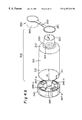
- FIG. 2A is a perspective view of the extension chamber of FIGS. 1A and 1B with an input end cap separated from the chamber housing and an output end cap shown removed from the outlet end of the chamber housing.
- FIG. 2B is a perspective view of FIG. 2A showing the input end cap positioned on the chamber housing and the output end cap removed from the output opening, but tethered to the output end of the chamber housing.
- FIG. 3A is a perspective view of the chamber housing of Fig. 2A showing an apertured barrier positioned at the curved transition from the inlet end to the outlet end.
- FIG. 3B is an enlarged perspective view showing the input end of the chamber housing and the circumferentially disposed circular apertures of the barrier at the output end of the invention.
- FIG. 4A is a view of FIG. 2A, partially in phantom, showing the wall thickness of the chamber housing, the internal structure of the input end cap and the structure of the output end cap which can cover the breathing end of the chamber housing.
- FIG. 4B is an enlarged view of the end cap of the invention with its tether connection to a fastening ring by which the end cap is secured to the chamber housing.
- FIG. 5A is an enlarged view of the exterior of the input cap for the chamber housing of the invention.
- FIG. 5B is an enlarged view showing the interior of the input cap of FIG. 5 A.
- FIGS. 6A and 6B are partial perspective views of a modification of the chamber of FIG. 2A showing a support of the invention for an umbrella valve shown in FIG. 6C to allow only inhalation operation of the chamber of the invention.
- FIG. 1A shows a medication system 100 of the invention formed by an aerosol extension chamber 300 preparatory to being positioned on a Metered Dosage Inhalation (MDI) aerosol source 200 .
- MDI Metered Dosage Inhalation
- the extension chamber 300 has been positioned on the output end 210 of the source 200 , and the outlet cap 350 of the chamber 300 has been removed to allow placement of the chamber outlet extension 320 in the mouth of a user U whose hand H is shown depressing a canister 220 which has been inserted into the body 230 of the dispenser 200 to apply aerosol medication.
- the extension chamber 300 of the invention is used in inhalation therapy to reduce the size and velocity of aerosol particles and droplets sprayed from the dispenser 200 , so that an increased amount of dispensed medication is deposited in the respiratory tract of a patient, instead of in the oropharynx above the large central airways of the lungs.
- the therapeutic efficiency of aerosol therapy is dependent upon ensuring that a sufficient amount of inhaled medication reaches the lungs.
- the extension chamber 300 of the invention achieves an enhanced therapeutic effect by creating back pressure within the chamber using a barrier grid with apertures of varying size; also by using a curved shoulder of the chamber to direct larger particles of the aerosol back into the chamber for size reduction, and by using a modified inlet for the chamber, supporting the aerosol source 200 to maintain centralized output flow into the chamber 300 .
- An important aspect of the invention is the use of a grid with multiple circular openings in order to optimize the performance of the chamber.
- the chamber 300 is formed by three sections.
- a main housing 310 is affixed to an output extension 320 at the position 330 of transition from the maximum diameter D 1 of the housing 310 to the reduced diameter D 2 of the output extension 320 .
- an apertured barrier 360 shown in detail in FIGS. 3A and 3B and described below.
- the extension chamber 300 Before being applied to the source 200 , the extension chamber 300 has the input end cap 340 secured to the input end of the main housing 310 , being guided into position by an alignment groove 311 at the skirt 312 of the housing 310 .
- the groove 311 engages a rib 341 - r on the interior wall 342 of the end cap 340 to assure proper positioning of the cap 340 on the skirt 312 , as shown in FIG. 2 B.
- the outlet end cap 350 has the ring 351 positioned on the extension 320 as shown in FIG. 2B on a support hook 314 at an opening 354 , so that when the cup 353 is removed from the extension 320 , as shown in FIG. 2B, the cup 353 will hang from the tether 352 at the side of the housing 310 and not interfere with user U of FIG. 1 B.
- the barrier disk 360 is formed by a circumferential set of apertures at different radii with a central aperture 361 (FIG. 3B) coincident with the axis A of the housing 310 , illustratively having a diameter of 0.093 inches.
- the central opening 361 is surrounded by four sets 362 through 365 of circumferential openings, with the openings of each different set having a different diameter.
- the set 362 is formed by nine openings at a radius R 2 , with each opening having a diameter of approximately 0.045 inches.
- the next set 363 at a radius R 3 includes eleven openings each having a diameter of approximately 0.065 inches.
- a fourth set 364 , at a radius R 4 includes sixteen apertures each having a diameter of approximately 0.070 inches.
- the final set 365 , at a radius R 5 includes 20 openings each with a diameter of approximately 0.080 inches.
- the large droplets and agglomerations of droplets formed upon discharge from the source 200 are dispersed uniformly through the spray medium. In some instances, however, large droplets and agglomerations of droplets become entrained. This effect is reduced due to the construction of the chamber 300 .
- the chamber housing 310 with the extension 320 may be of any medically safe resin or polymer and be formed by injection molding so that a single-piece, homogeneous chamber is produced having the barrier disk 360 integrally formed with, and extending across the interior of the chamber at the transition 330 between the input section 310 and the output section 320 .
- the chamber 300 is preferably made from a chemically resistant plastic.
- the housing 310 desirably is a copolyester, while the inlet 340 is desirably “santoprene” (thermo-elastic) or polyvinyl chloride (PVC).
- santoprene thermo-elastic
- PVC polyvinyl chloride
- the single-piece homogeneous extension chamber 300 Prior to receiving a dosage of the prescribed medication, the single-piece homogeneous extension chamber 300 is mounted upon the mouthpiece 210 of the inhaler 200 as shown in FIGS. 1A and 1B.
- the open end 343 of the input cap 340 is positioned on the mouthpiece 210 of FIG. 1 A.
- the opening 343 is proportioned to have side walls 344 - a and b, and 345 - a and b that correspond to the configuration of the mouthpiece 210 .
- the end cap 340 has a circular recess 341 to accommodate circular mouthpieces.
- the input cap 340 also has air entrainment apertures 348 to prevent restriction of end user inhalation flow rate.
- the opposed, parallel and linear side walls 344 - a and 344 - b extend into the interior of the housing 310 .
- the opposed arc segments 345 - a and 345 - b also extend into the interior of the housing 310 .
- Projections 349 - a and 349 - b in FIG. 5A control the distance between the end cap 340 and the body of the source, such as a metered-dose inhaler.
- Some sources have the 90 degree configuration as shown in FIGS. 1A and 1B where the mouthpiece 210 extends at a right angle with respect to the housing 230 of the source 200 .
- other sources cut the angle between the housing 230 and the mouthpiece 210 to 45 degrees so that when the source is inserted there is a danger that the mouthpiece will have an upward tilt that directs the input flow off axis. This possibility is avoided by the invention through the use of projections 349 - a and 349 - b which prevent the mouthpiece from adopting an upward tilt.
- the projections 349 - a and 349 - b of the invention increase the internal distance of the source 200 from the apertured disk 360 , thus increasing the distance for therapeutic aerosol formation.
- the additional projections or supports 349 - c and 349 - d help to prevent the occlusion of air entrainment apertures 348 .
- FIG. 5B Further stabilization for the mounting of the chamber 300 on the source 200 is provided by the internal structure of the end cap 340 shown in FIG. 5B, where the extended side walls 344 - a and 344 - b are supported by trapezoidal buffers 346 - a and 346 - b.
- Other trapezoidal buffers 347 - a and 347 - b join the respective arcuate walls 345 - a and 345 - b, with each buffer 347 - a and 347 - b having an internal reinforcement rib 347 - r.
- the inhalation device upon which the extension chamber 300 may be mounted is not simply limited to a metered-dose inhaler but may also include other inhalation devices, such as dry-powder inhalers or nebulizers, or other similar devices.
- a metered dose of medication is dispensed from the mouthpiece 210 .
- back pressure is applied by the internal disk 360 , together with a redirection of large droplets by the housing curvature 313 at the transition position 330 , so that a stream of appropriately fine particles can reach the lungs of the user.
- the larger particles and agglomerations redirected into the chamber are either deposited or reduced in size and joined to the outgoing stream.
- the invention provides inhalation therapy for less coordinated patients, comparable to the therapeutic achieved by patients with good inhalation skills, by adapting the extension chamber 300 to have a one-way valve and valve support at the transition position 330 .
- FIGS. 6A-6C One way of accomplishing this result is illustrated in FIGS. 6A-6C.
- the barrier disk 360 of FIG. 3A has been replaced by a valve support 660 on which is mounted the umbrella valve 680 shown in FIG. 6 C.
- the valve support 660 is formed by concentric rings 661 , 662 and 663 with radial arms 664 , 665 , 666 and 667 extending from the inner ring 661 , which has a positional notch 668 .
- the prong 681 shown in FIG. 6C is inserted into the central opening 671 of the ring 661 .
- This causes the butterfly segments 682 - 685 to lie upon the concentric rings and radial arms of the support 660 .
- the rings 661 - 663 include sector openings 671 and 672 in order to allow aerosol medication to pass through the output opening 320 and to reduce adherence of the segments 682 - 685 on the support 660 during inhalation.
- the umbrella valve 680 of FIG. 6C is shown having its prong 681 with an axial outer rib 688 to properly position butterfly segment 682 - 685 of the umbrella valve valve 680 onto the support.
- the prong 681 has a bulbous end 689 .
- the segments 682 - 685 are separated by grooves 684 which extend from the prong 681 to the circumference of the segments 682 - 685 . Grooves 687 allow each segment of the umbrella valve to move separately from one another.
- FIG. 6B The structure of the concentric rings 661 , 662 and 663 , and the radial arms 664 , 665 , 666 and 667 extending from the inner ring 661 , is shown in FIG. 6B as viewed from the insert end of the chamber with the end cap 340 removed.
- FIG. 6A While the rings and arms of FIG. 6A are flat to accommodate the umbrella valve 680 , that structure in FIG. 6B has a triangular cross-section in order to promote through-flow and reduce aerosol impaction, while increasing the structural integrity of the support 660 for the umbrella valve 680 on its flat side.
- one-way valve 600 of FIG. 6 takes the form of a umbrella valve 680 covering a support 660 , other forms of one-way valve may be employed.
- The serves as a baffle to force the impaction of high velocity non-therapeutic particles that would otherwise end in the mouth.
Abstract
Description
Claims (9)
Priority Applications (3)
| Application Number | Priority Date | Filing Date | Title |
|---|---|---|---|
| US09/205,279 US6257231B1 (en) | 1998-12-03 | 1998-12-03 | Aerosol enhancement |
| PCT/US2000/008857 WO2001074429A1 (en) | 1998-12-03 | 2000-04-03 | Aerosol enhancement |
| US09/901,546 US20020005195A1 (en) | 1998-12-03 | 2001-07-09 | Aerosol enhancement |
Applications Claiming Priority (2)
| Application Number | Priority Date | Filing Date | Title |
|---|---|---|---|
| US09/205,279 US6257231B1 (en) | 1998-12-03 | 1998-12-03 | Aerosol enhancement |
| PCT/US2000/008857 WO2001074429A1 (en) | 1998-12-03 | 2000-04-03 | Aerosol enhancement |
Related Child Applications (1)
| Application Number | Title | Priority Date | Filing Date |
|---|---|---|---|
| US09/901,546 Continuation US20020005195A1 (en) | 1998-12-03 | 2001-07-09 | Aerosol enhancement |
Publications (1)
| Publication Number | Publication Date |
|---|---|
| US6257231B1 true US6257231B1 (en) | 2001-07-10 |
Family
ID=26680184
Family Applications (1)
| Application Number | Title | Priority Date | Filing Date |
|---|---|---|---|
| US09/205,279 Expired - Lifetime US6257231B1 (en) | 1998-12-03 | 1998-12-03 | Aerosol enhancement |
Country Status (2)
| Country | Link |
|---|---|
| US (1) | US6257231B1 (en) |
| WO (1) | WO2001074429A1 (en) |
Cited By (27)
| Publication number | Priority date | Publication date | Assignee | Title |
|---|---|---|---|---|
| US6595206B2 (en) * | 2001-07-13 | 2003-07-22 | John Vito | Extendable spacer device and metered dose inhaler |
| US20030205226A1 (en) * | 2002-05-02 | 2003-11-06 | Pre Holding, Inc. | Aerosol medication inhalation system |
| US20040094148A1 (en) * | 1998-12-09 | 2004-05-20 | Amar Lulla | Spacer device for inhaler |
| US6745763B2 (en) * | 1998-10-27 | 2004-06-08 | Garth T. Webb | Vaporizing device for administering sterile medication |
| US20050268915A1 (en) * | 2004-06-07 | 2005-12-08 | Willem Wassenaar | Nasal adaptation of an oral inhaler device |
| US20060021617A1 (en) * | 2000-07-14 | 2006-02-02 | Hoffman Andrew M | Drug delivery device for animals |
| US20080035142A1 (en) * | 2004-10-15 | 2008-02-14 | Amar Lulla | Spacer |
| US7343914B2 (en) * | 2001-09-06 | 2008-03-18 | Microdose Technologies, Inc. | Adaptors for inhalers to improve performance |
| US20080257345A1 (en) * | 2003-04-16 | 2008-10-23 | Trudell Medical International | Antistatic medication delivery apparatus |
| US20080283541A1 (en) * | 2007-05-15 | 2008-11-20 | Consort Medical Plc | Dispensing apparatus |
| US20090007905A1 (en) * | 2007-07-03 | 2009-01-08 | John Vito | Spacer/holding chamber for pressurized metered dose inhaler |
| US20100083773A1 (en) * | 2008-10-04 | 2010-04-08 | Eppendorf Ag | Sample carrier |
| USRE43174E1 (en) | 2000-04-11 | 2012-02-14 | Trudell Medical International | Aerosol delivery apparatus |
| EP2172239A3 (en) * | 2008-10-06 | 2012-07-18 | Canon Kabushiki Kaisha | Discharge head and droplet discharging device |
| US8695589B2 (en) | 2011-12-06 | 2014-04-15 | Anthony J. Mullane | Inhaler assist device |
| US20150068524A1 (en) * | 2011-12-22 | 2015-03-12 | Sanofi Sa | System for a Drug Delivery Device |
| US20160051776A1 (en) * | 2013-03-21 | 2016-02-25 | Koninklijke Philips N.V. | System and method for monitoring usage of a respiratory medication delivery device |
| US9566397B2 (en) | 2007-05-15 | 2017-02-14 | Joseph Dee Faram | Small-volume nebulizers and methods of use thereof |
| US20170113008A1 (en) * | 2014-06-06 | 2017-04-27 | Rijksuniversiteit Groningen | A breath actuated dry powder inhaler |
| US9700689B2 (en) | 2002-05-21 | 2017-07-11 | Trudell Medical International | Medication delivery apparatus and system and methods for the use and assembly thereof |
| US10149950B2 (en) | 2007-05-15 | 2018-12-11 | Caddo Medical Technologies Llc | Pre-filled, small-volume nebulizer and method of manufacture |
| US10258758B1 (en) | 2018-04-20 | 2019-04-16 | Caddo Medical Technologies Llc | Flow controlled valve for a small-volume nebulizer |
| WO2019082056A1 (en) * | 2017-10-25 | 2019-05-02 | Philip Morris Products S.A. | Inhaler with boundary element |
| US10342935B2 (en) | 2017-11-21 | 2019-07-09 | Caddo Medical Technologies Llc | Internal nebulizer seal and method of use |
| WO2021222087A1 (en) * | 2020-04-30 | 2021-11-04 | Kindeva Drug Delivery L.P. | Cover assembly and actuator for inhaler |
| US11577033B2 (en) | 2018-06-05 | 2023-02-14 | Medline Industries, Lp | Valved spacer for inhalation device |
| USD1010101S1 (en) | 2020-09-18 | 2024-01-02 | Trudell Medical International | Holding chamber |
Families Citing this family (1)
| Publication number | Priority date | Publication date | Assignee | Title |
|---|---|---|---|---|
| NL2023033B1 (en) * | 2019-04-30 | 2020-11-23 | Medspray B V | Spray inhaler device |
Citations (14)
| Publication number | Priority date | Publication date | Assignee | Title |
|---|---|---|---|---|
| US3097645A (en) * | 1960-03-22 | 1963-07-16 | Victor E Lester | Nebulizer |
| US4470412A (en) * | 1982-03-19 | 1984-09-11 | Trutek Research, Inc. | Inhalation valve |
| US4690332A (en) * | 1983-11-28 | 1987-09-01 | Nathaniel Hughes | Single inlet prepackaged inhaler |
| US4706663A (en) * | 1986-04-25 | 1987-11-17 | Makiej Paul A | Particle catcher for inhalation devices |
| US4953545A (en) * | 1989-10-18 | 1990-09-04 | Mccarty Jerry | Disposable respiratory medication dispersion chamber |
| US5301663A (en) * | 1991-07-16 | 1994-04-12 | Healthscan Products, Inc. | Aerosol delivery system |
| US5320094A (en) * | 1992-01-10 | 1994-06-14 | The Johns Hopkins University | Method of administering insulin |
| US5415162A (en) * | 1994-01-18 | 1995-05-16 | Glaxo Inc. | Multi-dose dry powder inhalation device |
| US5788665A (en) * | 1989-08-28 | 1998-08-04 | Alliance Pharmaceutical Corp. | Apparatus for pulmonary therapy |
| US5791340A (en) * | 1994-03-17 | 1998-08-11 | Ambu International A/S | Resuscitator |
| US5842467A (en) * | 1996-06-19 | 1998-12-01 | Greco; Michael | Metered dose inhaler and ambulatory manual breathing unit combination |
| US5848588A (en) * | 1994-05-25 | 1998-12-15 | Trudell Medical Group | Backpiece for receiving an MDI adapter in an aerosolization spacer |
| US5899201A (en) * | 1993-05-26 | 1999-05-04 | Minnesota Mining And Manufacturing Company | Aerosol actuator |
| US5954047A (en) * | 1997-10-17 | 1999-09-21 | Systemic Pulmonary Development, Ltd. | Methods and apparatus for delivering aerosolized medication |
-
1998
- 1998-12-03 US US09/205,279 patent/US6257231B1/en not_active Expired - Lifetime
-
2000
- 2000-04-03 WO PCT/US2000/008857 patent/WO2001074429A1/en not_active Application Discontinuation
Patent Citations (15)
| Publication number | Priority date | Publication date | Assignee | Title |
|---|---|---|---|---|
| US3097645A (en) * | 1960-03-22 | 1963-07-16 | Victor E Lester | Nebulizer |
| US4470412A (en) * | 1982-03-19 | 1984-09-11 | Trutek Research, Inc. | Inhalation valve |
| US4690332A (en) * | 1983-11-28 | 1987-09-01 | Nathaniel Hughes | Single inlet prepackaged inhaler |
| US4702415A (en) * | 1983-11-28 | 1987-10-27 | Vortran Corporation | Aerosol producing device |
| US4706663A (en) * | 1986-04-25 | 1987-11-17 | Makiej Paul A | Particle catcher for inhalation devices |
| US5788665A (en) * | 1989-08-28 | 1998-08-04 | Alliance Pharmaceutical Corp. | Apparatus for pulmonary therapy |
| US4953545A (en) * | 1989-10-18 | 1990-09-04 | Mccarty Jerry | Disposable respiratory medication dispersion chamber |
| US5301663A (en) * | 1991-07-16 | 1994-04-12 | Healthscan Products, Inc. | Aerosol delivery system |
| US5320094A (en) * | 1992-01-10 | 1994-06-14 | The Johns Hopkins University | Method of administering insulin |
| US5899201A (en) * | 1993-05-26 | 1999-05-04 | Minnesota Mining And Manufacturing Company | Aerosol actuator |
| US5415162A (en) * | 1994-01-18 | 1995-05-16 | Glaxo Inc. | Multi-dose dry powder inhalation device |
| US5791340A (en) * | 1994-03-17 | 1998-08-11 | Ambu International A/S | Resuscitator |
| US5848588A (en) * | 1994-05-25 | 1998-12-15 | Trudell Medical Group | Backpiece for receiving an MDI adapter in an aerosolization spacer |
| US5842467A (en) * | 1996-06-19 | 1998-12-01 | Greco; Michael | Metered dose inhaler and ambulatory manual breathing unit combination |
| US5954047A (en) * | 1997-10-17 | 1999-09-21 | Systemic Pulmonary Development, Ltd. | Methods and apparatus for delivering aerosolized medication |
Cited By (51)
| Publication number | Priority date | Publication date | Assignee | Title |
|---|---|---|---|---|
| US6745763B2 (en) * | 1998-10-27 | 2004-06-08 | Garth T. Webb | Vaporizing device for administering sterile medication |
| US7404400B2 (en) | 1998-12-09 | 2008-07-29 | Cipla Limited | Spacer device for inhaler |
| US20040094148A1 (en) * | 1998-12-09 | 2004-05-20 | Amar Lulla | Spacer device for inhaler |
| USRE43174E1 (en) | 2000-04-11 | 2012-02-14 | Trudell Medical International | Aerosol delivery apparatus |
| USRE45068E1 (en) | 2000-04-11 | 2014-08-12 | Trudell Medical International | Aerosol delivery apparatus |
| USRE46050E1 (en) | 2000-04-11 | 2016-07-05 | Trudell Medical International | Aerosol delivery apparatus |
| US20060021617A1 (en) * | 2000-07-14 | 2006-02-02 | Hoffman Andrew M | Drug delivery device for animals |
| US6595206B2 (en) * | 2001-07-13 | 2003-07-22 | John Vito | Extendable spacer device and metered dose inhaler |
| US20080228099A1 (en) * | 2001-09-06 | 2008-09-18 | Abrams Andrew L | Adaptors for inhalers to improve performance |
| US7343914B2 (en) * | 2001-09-06 | 2008-03-18 | Microdose Technologies, Inc. | Adaptors for inhalers to improve performance |
| US20050039741A1 (en) * | 2002-05-02 | 2005-02-24 | Pari Innovative Manufacturers, Inc. | Aerosol medication inhalation system |
| US20060011196A2 (en) * | 2002-05-02 | 2006-01-19 | Pari Innovative Manufacturers, Inc. | Aerosol Medication Inhalation System |
| US9308335B2 (en) | 2002-05-02 | 2016-04-12 | Pre Holding, Inc. | Aerosol medication inhalation system |
| US8973571B1 (en) | 2002-05-02 | 2015-03-10 | Pre Holding, Inc. | Aerosol medication inhalation system |
| US7562656B2 (en) * | 2002-05-02 | 2009-07-21 | Hydrate, Inc. | Aerosol medication inhalation system |
| US8459252B2 (en) | 2002-05-02 | 2013-06-11 | Pari Innovative Manufacturers, Inc. | Aerosol medication inhalation system |
| US20030205226A1 (en) * | 2002-05-02 | 2003-11-06 | Pre Holding, Inc. | Aerosol medication inhalation system |
| US8074641B2 (en) | 2002-05-02 | 2011-12-13 | Pre Holdings, Inc. | Aerosol medication inhalation system |
| US20090090355A1 (en) * | 2002-05-02 | 2009-04-09 | Pari Innovative Manufacturers | Aerosol medication inhalation system |
| US9814849B2 (en) | 2002-05-21 | 2017-11-14 | Trudell Medical International | Medication delivery apparatus and system and methods for the use and assembly thereof |
| US9700689B2 (en) | 2002-05-21 | 2017-07-11 | Trudell Medical International | Medication delivery apparatus and system and methods for the use and assembly thereof |
| US10881816B2 (en) | 2002-05-21 | 2021-01-05 | Trudell Medical International | Medication delivery apparatus and system and methods for the use and assembly thereof |
| US20080257345A1 (en) * | 2003-04-16 | 2008-10-23 | Trudell Medical International | Antistatic medication delivery apparatus |
| US7448385B2 (en) * | 2004-06-07 | 2008-11-11 | Purepharm Inc. | Nasal adaptation of an oral inhaler device |
| US20050268915A1 (en) * | 2004-06-07 | 2005-12-08 | Willem Wassenaar | Nasal adaptation of an oral inhaler device |
| US20090050158A1 (en) * | 2004-06-07 | 2009-02-26 | Wilem Wassenaar | Nasal adaptation of an oral inhaler device |
| US20080035142A1 (en) * | 2004-10-15 | 2008-02-14 | Amar Lulla | Spacer |
| GB2451225A (en) * | 2007-05-15 | 2009-01-28 | Bespak Plc | Improvements in or relating to dispensing apparatus |
| US20080283541A1 (en) * | 2007-05-15 | 2008-11-20 | Consort Medical Plc | Dispensing apparatus |
| GB2451225B (en) * | 2007-05-15 | 2009-07-08 | Bespak Plc | Improvements in or relating to dispensing apparatus |
| US10149950B2 (en) | 2007-05-15 | 2018-12-11 | Caddo Medical Technologies Llc | Pre-filled, small-volume nebulizer and method of manufacture |
| US9566397B2 (en) | 2007-05-15 | 2017-02-14 | Joseph Dee Faram | Small-volume nebulizers and methods of use thereof |
| US20090007905A1 (en) * | 2007-07-03 | 2009-01-08 | John Vito | Spacer/holding chamber for pressurized metered dose inhaler |
| US7832393B2 (en) * | 2007-07-03 | 2010-11-16 | John Vito | Spacer/holding chamber for pressurized metered dose inhaler |
| US20100083773A1 (en) * | 2008-10-04 | 2010-04-08 | Eppendorf Ag | Sample carrier |
| EP2172239A3 (en) * | 2008-10-06 | 2012-07-18 | Canon Kabushiki Kaisha | Discharge head and droplet discharging device |
| US8695589B2 (en) | 2011-12-06 | 2014-04-15 | Anthony J. Mullane | Inhaler assist device |
| US20150068524A1 (en) * | 2011-12-22 | 2015-03-12 | Sanofi Sa | System for a Drug Delivery Device |
| US10342936B2 (en) * | 2013-03-21 | 2019-07-09 | Koninklijke Philips N.V. | System and method for monitoring usage of a respiratory medication delivery device |
| US20160051776A1 (en) * | 2013-03-21 | 2016-02-25 | Koninklijke Philips N.V. | System and method for monitoring usage of a respiratory medication delivery device |
| US10561809B2 (en) * | 2014-06-06 | 2020-02-18 | Rijksuniversiteit Groningen | Breath actuated dry powder inhaler |
| US20170113008A1 (en) * | 2014-06-06 | 2017-04-27 | Rijksuniversiteit Groningen | A breath actuated dry powder inhaler |
| WO2019082056A1 (en) * | 2017-10-25 | 2019-05-02 | Philip Morris Products S.A. | Inhaler with boundary element |
| CN111163651A (en) * | 2017-10-25 | 2020-05-15 | 菲利普莫里斯生产公司 | Inhaler with boundary element |
| JP2021500015A (en) * | 2017-10-25 | 2021-01-07 | フィリップ・モーリス・プロダクツ・ソシエテ・アノニム | Inhaler with boundary elements |
| US10342935B2 (en) | 2017-11-21 | 2019-07-09 | Caddo Medical Technologies Llc | Internal nebulizer seal and method of use |
| US10576221B2 (en) | 2017-11-21 | 2020-03-03 | Caddo Medical Technologies Llc | Internal nebulizer seal and method of use |
| US10258758B1 (en) | 2018-04-20 | 2019-04-16 | Caddo Medical Technologies Llc | Flow controlled valve for a small-volume nebulizer |
| US11577033B2 (en) | 2018-06-05 | 2023-02-14 | Medline Industries, Lp | Valved spacer for inhalation device |
| WO2021222087A1 (en) * | 2020-04-30 | 2021-11-04 | Kindeva Drug Delivery L.P. | Cover assembly and actuator for inhaler |
| USD1010101S1 (en) | 2020-09-18 | 2024-01-02 | Trudell Medical International | Holding chamber |
Also Published As
| Publication number | Publication date |
|---|---|
| WO2001074429A1 (en) | 2001-10-11 |
Similar Documents
| Publication | Publication Date | Title |
|---|---|---|
| US6257231B1 (en) | Aerosol enhancement | |
| JP4578689B2 (en) | Aerosol drug delivery device and method | |
| US20020005195A1 (en) | Aerosol enhancement | |
| JP4688391B2 (en) | Internal vortex mechanism for inhalation devices | |
| US7025056B2 (en) | Assymetric inhaler | |
| CA1077799A (en) | Attachment to medicinal inhalation devices | |
| US7404400B2 (en) | Spacer device for inhaler | |
| KR100366323B1 (en) | Pediatric suction chamber for use in combination with metered dose inhalers | |
| JP2001518323A (en) | Aerosol drug delivery device and system | |
| US7107987B2 (en) | Spacer for delivery of medications from an inhaler to children and breathing impaired patients | |
| WO1986001731A1 (en) | All purpose nebulizer | |
| US20050016542A1 (en) | Intra-tracheal aerosol delivery system and method of using same | |
| EP2653181B1 (en) | Powder medicament mouthpiece and application | |
| JP2003531693A (en) | Respirator spacer assembly | |
| JP7182561B2 (en) | Spacer device for nebulizer | |
| WO2022113705A1 (en) | Inhalation aid | |
| AU2000244512A1 (en) | Aerosol enhancement | |
| AU2017271493B2 (en) | Inhaler spacer | |
| EP0534749A1 (en) | Inhaler for aerosol medications |
Legal Events
| Date | Code | Title | Description |
|---|---|---|---|
| AS | Assignment |
Owner name: FERRARIS MEDICAL, INC., NEW YORK Free format text: ASSIGNMENT OF ASSIGNORS INTEREST;ASSIGNORS:SHICK, JOHN;MALYS, DAVID;PARCO, JACK;REEL/FRAME:012181/0305 Effective date: 19981207 |
|
| STCF | Information on status: patent grant |
Free format text: PATENTED CASE |
|
| AS | Assignment |
Owner name: PULMONARY DATA SERVICES, INC., COLORADO Free format text: MERGER;ASSIGNOR:FERRARIS MEDICAL, INC.;REEL/FRAME:015201/0428 Effective date: 20030417 |
|
| FPAY | Fee payment |
Year of fee payment: 4 |
|
| AS | Assignment |
Owner name: FERRARIS RESPIRATORY, INC., COLORADO Free format text: CHANGE OF NAME;ASSIGNOR:PULMONARY DATA SERVICES, INC.;REEL/FRAME:019511/0518 Effective date: 20041005 |
|
| AS | Assignment |
Owner name: NSPIRE HEALTH, INC., COLORADO Free format text: CHANGE OF NAME;ASSIGNOR:FERRARIS RESPIRATORY, INC.;REEL/FRAME:019520/0666 Effective date: 20070103 |
|
| FPAY | Fee payment |
Year of fee payment: 8 |
|
| AS | Assignment |
Owner name: MONTAGE CAPITAL, LLC,CALIFORNIA Free format text: SECURITY AGREEMENT;ASSIGNOR:NSPIRE HEALTH, INC.;REEL/FRAME:024055/0252 Effective date: 20100305 Owner name: MONTAGE CAPITAL, LLC, CALIFORNIA Free format text: SECURITY AGREEMENT;ASSIGNOR:NSPIRE HEALTH, INC.;REEL/FRAME:024055/0252 Effective date: 20100305 |
|
| AS | Assignment |
Owner name: NSPIRE HEALTH, INC., COLORADO Free format text: RELEASE BY SECURED PARTY;ASSIGNOR:MONTAGE CAPITAL, LLC;REEL/FRAME:027897/0510 Effective date: 20120314 |
|
| FPAY | Fee payment |
Year of fee payment: 12 |
|
| AS | Assignment |
Owner name: MONTAGE CAPITAL II, L.P., CALIFORNIA Free format text: SECURITY INTEREST;ASSIGNORS:NSPIRE HEALTH, INC.;NSPIRE HEALTH, L.L.C.;REEL/FRAME:046231/0024 Effective date: 20180628 |
|
| AS | Assignment |
Owner name: NSPIRE HEALTH, INC., COLORADO Free format text: RELEASE BY SECURED PARTY;ASSIGNOR:MONTAGE CAPITAL II, L.P.;REEL/FRAME:050941/0381 Effective date: 20191104 Owner name: NSPIRE HEALTH, L.L.C., COLORADO Free format text: RELEASE BY SECURED PARTY;ASSIGNOR:MONTAGE CAPITAL II, L.P.;REEL/FRAME:050941/0381 Effective date: 20191104 |
|
| AS | Assignment |
Owner name: KOKO, LLC, COLORADO Free format text: ASSIGNMENT OF ASSIGNORS INTEREST;ASSIGNORS:NSPIRE HEALTH, INC.;NSPIRE HEALTH, LLC;REEL/FRAME:052612/0389 Effective date: 20200505 |
|
| AS | Assignment |
Owner name: HERACLES F, LLC, UNITED KINGDOM Free format text: SECURITY INTEREST;ASSIGNOR:KOKO, LLC;REEL/FRAME:052626/0973 Effective date: 20200505 |
|
| AS | Assignment |
Owner name: KOKO IT, LLC, COLORADO Free format text: ASSIGNMENT OF ASSIGNORS INTEREST;ASSIGNOR:KOKO, LLC;REEL/FRAME:055831/0990 Effective date: 20210402 |