US9964922B2 - Developing cartridge providing layout of electrodes and detection gear - Google Patents
Developing cartridge providing layout of electrodes and detection gear Download PDFInfo
- Publication number
- US9964922B2 US9964922B2 US15/473,123 US201715473123A US9964922B2 US 9964922 B2 US9964922 B2 US 9964922B2 US 201715473123 A US201715473123 A US 201715473123A US 9964922 B2 US9964922 B2 US 9964922B2
- Authority
- US
- United States
- Prior art keywords
- developing
- gear
- roller shaft
- protrusion
- detection gear
- Prior art date
- Legal status (The legal status is an assumption and is not a legal conclusion. Google has not performed a legal analysis and makes no representation as to the accuracy of the status listed.)
- Active
Links
Images


Classifications
-
- G—PHYSICS
- G03—PHOTOGRAPHY; CINEMATOGRAPHY; ANALOGOUS TECHNIQUES USING WAVES OTHER THAN OPTICAL WAVES; ELECTROGRAPHY; HOLOGRAPHY
- G03G—ELECTROGRAPHY; ELECTROPHOTOGRAPHY; MAGNETOGRAPHY
- G03G21/00—Arrangements not provided for by groups G03G13/00 - G03G19/00, e.g. cleaning, elimination of residual charge
- G03G21/16—Mechanical means for facilitating the maintenance of the apparatus, e.g. modular arrangements
- G03G21/18—Mechanical means for facilitating the maintenance of the apparatus, e.g. modular arrangements using a processing cartridge, whereby the process cartridge comprises at least two image processing means in a single unit
- G03G21/1839—Means for handling the process cartridge in the apparatus body
- G03G21/1867—Means for handling the process cartridge in the apparatus body for electrically connecting the process cartridge to the apparatus, electrical connectors, power supply
-
- G—PHYSICS
- G03—PHOTOGRAPHY; CINEMATOGRAPHY; ANALOGOUS TECHNIQUES USING WAVES OTHER THAN OPTICAL WAVES; ELECTROGRAPHY; HOLOGRAPHY
- G03G—ELECTROGRAPHY; ELECTROPHOTOGRAPHY; MAGNETOGRAPHY
- G03G15/00—Apparatus for electrographic processes using a charge pattern
- G03G15/06—Apparatus for electrographic processes using a charge pattern for developing
- G03G15/08—Apparatus for electrographic processes using a charge pattern for developing using a solid developer, e.g. powder developer
- G03G15/0822—Arrangements for preparing, mixing, supplying or dispensing developer
- G03G15/0865—Arrangements for supplying new developer
- G03G15/0867—Arrangements for supplying new developer cylindrical developer cartridges, e.g. toner bottles for the developer replenishing opening
- G03G15/0868—Toner cartridges fulfilling a continuous function within the electrographic apparatus during the use of the supplied developer material, e.g. toner discharge on demand, storing residual toner, acting as an active closure for the developer replenishing opening
-
- G—PHYSICS
- G03—PHOTOGRAPHY; CINEMATOGRAPHY; ANALOGOUS TECHNIQUES USING WAVES OTHER THAN OPTICAL WAVES; ELECTROGRAPHY; HOLOGRAPHY
- G03G—ELECTROGRAPHY; ELECTROPHOTOGRAPHY; MAGNETOGRAPHY
- G03G21/00—Arrangements not provided for by groups G03G13/00 - G03G19/00, e.g. cleaning, elimination of residual charge
- G03G21/16—Mechanical means for facilitating the maintenance of the apparatus, e.g. modular arrangements
- G03G21/1642—Mechanical means for facilitating the maintenance of the apparatus, e.g. modular arrangements for connecting the different parts of the apparatus
- G03G21/1652—Electrical connection means
-
- G—PHYSICS
- G03—PHOTOGRAPHY; CINEMATOGRAPHY; ANALOGOUS TECHNIQUES USING WAVES OTHER THAN OPTICAL WAVES; ELECTROGRAPHY; HOLOGRAPHY
- G03G—ELECTROGRAPHY; ELECTROPHOTOGRAPHY; MAGNETOGRAPHY
- G03G21/00—Arrangements not provided for by groups G03G13/00 - G03G19/00, e.g. cleaning, elimination of residual charge
- G03G21/16—Mechanical means for facilitating the maintenance of the apparatus, e.g. modular arrangements
- G03G21/18—Mechanical means for facilitating the maintenance of the apparatus, e.g. modular arrangements using a processing cartridge, whereby the process cartridge comprises at least two image processing means in a single unit
- G03G21/1839—Means for handling the process cartridge in the apparatus body
- G03G21/1857—Means for handling the process cartridge in the apparatus body for transmitting mechanical drive power to the process cartridge, drive mechanisms, gears, couplings, braking mechanisms
-
- G—PHYSICS
- G03—PHOTOGRAPHY; CINEMATOGRAPHY; ANALOGOUS TECHNIQUES USING WAVES OTHER THAN OPTICAL WAVES; ELECTROGRAPHY; HOLOGRAPHY
- G03G—ELECTROGRAPHY; ELECTROPHOTOGRAPHY; MAGNETOGRAPHY
- G03G21/00—Arrangements not provided for by groups G03G13/00 - G03G19/00, e.g. cleaning, elimination of residual charge
- G03G21/16—Mechanical means for facilitating the maintenance of the apparatus, e.g. modular arrangements
- G03G21/18—Mechanical means for facilitating the maintenance of the apparatus, e.g. modular arrangements using a processing cartridge, whereby the process cartridge comprises at least two image processing means in a single unit
- G03G21/1875—Mechanical means for facilitating the maintenance of the apparatus, e.g. modular arrangements using a processing cartridge, whereby the process cartridge comprises at least two image processing means in a single unit provided with identifying means or means for storing process- or use parameters, e.g. lifetime of the cartridge
- G03G21/1896—Mechanical means for facilitating the maintenance of the apparatus, e.g. modular arrangements using a processing cartridge, whereby the process cartridge comprises at least two image processing means in a single unit provided with identifying means or means for storing process- or use parameters, e.g. lifetime of the cartridge mechanical or optical identification means, e.g. protrusions, bar codes
-
- G—PHYSICS
- G03—PHOTOGRAPHY; CINEMATOGRAPHY; ANALOGOUS TECHNIQUES USING WAVES OTHER THAN OPTICAL WAVES; ELECTROGRAPHY; HOLOGRAPHY
- G03G—ELECTROGRAPHY; ELECTROPHOTOGRAPHY; MAGNETOGRAPHY
- G03G2221/00—Processes not provided for by group G03G2215/00, e.g. cleaning or residual charge elimination
- G03G2221/16—Mechanical means for facilitating the maintenance of the apparatus, e.g. modular arrangements and complete machine concepts
- G03G2221/1651—Mechanical means for facilitating the maintenance of the apparatus, e.g. modular arrangements and complete machine concepts for connecting the different parts
- G03G2221/166—Electrical connectors
Definitions
- the present disclosure relates to a developing cartridge for use in an image forming apparatus.
- an image forming apparatus capable of determining whether a developing cartridge is attached to the apparatus or capable of identifying specifications of the developing cartridge.
- an image forming apparatus includes a sensor for detecting a protrusion of a detection gear provided at a developing cartridge, and the image forming apparatus determines whether the developing cartridge is attached to the image forming apparatus or not.
- prior art also discloses an image-forming device including a developing electrode and a supply electrode.
- the developing electrode is a bearing for the developing roller
- the supply electrode is a bearing for the supply roller.
- the developing electrode and supply electrode contact corresponding electrodes in the image-forming device in the axial direction of the developing roller.
- prior art also discloses an image-forming apparatus including a detection gear and a developing electrode.
- the detection gear and the developing electrode are positioned at a same side in an axial direction of a developing roller.
- the detection gear and developing electrode are arranged at the same side of the developing cartridge in the axial direction in order to make the developing cartridge as compact as possible.
- the protrusion on the detection gear may scrape against electrical contacts on the developing electrodes provided at the image-forming apparatus, or the developing electrode and/or supply electrode may scrape against a sensor at the image-forming apparatus provided for detecting the detection gear, depending on the layout of the developing electrode, supply electrode, and detection gear at the developing cartridge.
- a developing cartridge including: a developing roller, a casing, a supply roller, a coupling, a developing gear, a supply gear, an agitator, a first agitator gear, a second agitator gear, a developing electrode, a supply electrode, a detection gear, and a first protrusion.
- the developing roller includes a developing roller shaft extending in a first direction.
- the developing roller is rotatable about the developing roller shaft.
- the casing is configured to accommodate therein developing agent.
- the casing includes a first frame and a second frame facing the first frame in a second direction crossing the first direction.
- the developing roller is positioned at one end portion of the casing in a third direction crossing the first direction and the second direction.
- the supply roller includes a supply roller shaft extending in the first direction.
- the supply roller is rotatable about the supply roller shaft.
- the coupling is rotatable about a first axis extending in the first direction.
- the coupling is positioned at one end of the casing in the first direction.
- the developing gear is mounted to the developing roller shaft.
- the developing gear is rotatable together with the coupling.
- the developing gear is positioned at the one end of the casing in the first direction.
- the supply gear is mounted to the supply roller shaft.
- the supply gear is rotatable together with the coupling.
- the supply gear is positioned at the one end of the casing in the first direction.
- the agitator is rotatable together with the coupling about a second axis extending in the first direction.
- the agitator is configured to agitate the developing agent.
- the first agitator gear is positioned at the one end of the casing in the first direction.
- the first agitator gear is mounted to the agitator.
- the first agitator gear is rotatable together with the agitator in accordance with the rotation of the coupling.
- the second agitator gear is mounted to the agitator.
- the second agitator gear is rotatable together with the agitator.
- the second agitator gear is positioned at another end of the casing in the first direction.
- the developing electrode is positioned at the other end of the casing in the first direction.
- the developing electrode is configured to supply electric power to the developing roller shaft.
- the developing electrode includes: a first electrical contact, and a second electrical contact.
- the first electrical contact is in contact with the developing roller shaft.
- the second electrical contact is positioned closer to the developing roller shaft than the second agitator gear is to the developing roller shaft in the third direction.
- the second electrical contact is positioned farther from the developing roller shaft than the first electrical contact is from the developing roller shaft in the second direction and the third direction.
- the supply electrode is positioned at the other end of the casing in the first direction.
- the supply electrode is configured to supply electric power to the supply roller shaft.
- the supply electrode includes: a first electrical contact, and a second electrical contact.
- the first electrical contact is in contact with the supply roller shaft.
- the second electrical contact is positioned closer to the developing roller shaft than the second agitator gear is to the developing roller shaft in the third direction.
- the second electrical contact of the supply electrode is positioned farther from the developing roller shaft than the second electrical contact of the developing electrode is from the developing roller shaft in the second direction and the third direction.
- the detection gear is configured to engage with the second agitator gear.
- the detection gear is rotatable together with the second agitator gear from a first position to a second position.
- the detection gear is positioned at the other end of the casing in the first direction.
- the detection gear is positioned farther from the developing roller shaft than the second electrical contact of the supply electrode is from the developing roller shaft in the third direction.
- the first protrusion is movable together with the detection gear. A distal end of the first protrusion is positioned farther from the developing roller shaft than the second electrical contact of the supply electrode is from the developing roller shaft in the second direction and the third direction in a state where the detection gear is at the first position.
- FIG. 1 is a cross-sectional view of a printer provided with a developing cartridge according to one embodiment
- FIG. 2 is a cross-sectional view of a casing of the developing cartridge according to the embodiment
- FIG. 3 is a perspective view of the developing cartridge according to the embodiment, and particularly illustrating one side portion of the cartridge as viewed in a first direction;
- FIG. 4 is an exploded perspective view illustrating components disposed at the one side portion of the casing of the developing cartridge according to the embodiment
- FIG. 5 is a perspective view of the developing cartridge according to the embodiment, and particularly illustrating another side portion of the cartridge as viewed in the first direction;
- FIG. 6 is an exploded perspective view illustrating components disposed at the other side portion of the casing of the developing cartridge according to the embodiment
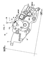
- FIG. 7 is a side view of the developing cartridge according to the embodiment and particularly showing the other side of the developing cartridge in the first direction;
- FIG. 8( a ) is a view illustrating a first position of a detection gear in the developing cartridge according to the embodiment, when viewed from an outside of a gear cover;
- FIG. 8( b ) is a view illustrating the first position of the detection gear in the developing cartridge according to the embodiment, when viewed from an inside of the gear cover;
- FIG. 9( a ) is a view illustrating an actuator positioned between a first protrusion and a third protrusion in the developing cartridge according to the embodiment
- FIG. 9( b ) is a view illustrating the actuator in contact with the third protrusion in the developing cartridge according to the embodiment.
- FIG. 9( c ) is a view illustrating the actuator positioned between the third protrusion and the second protrusion in the developing cartridge according to the embodiment
- FIG. 10( a ) is a view illustrating a second position of the detection gear in the developing cartridge according to the embodiment, when viewed from the outside of the gear cover;
- FIG. 10 ( b ) is a view illustrating the second position of the detection gear in the developing cartridge according to the embodiment, when viewed from the inside of the gear cover.
- FIGS. 1 through 10 ( b ) A developing cartridge according to one embodiment will be described with reference to FIGS. 1 through 10 ( b ).
- FIG. 1 illustrates a laser printer 1 as an example of the image forming apparatus.
- the laser printer 1 primarily includes a housing 2 , a sheet-feeding unit 3 , an image-forming unit 4 , and a control unit CU.
- the housing 2 has a front cover 2 A, and a discharge tray 2 B positioned at a top of the housing 2 .
- the sheet-feeding unit 3 and image-forming unit 4 are disposed in the housing 2 .
- a developing cartridge 10 described later can be detached from and attached to the housing 2 .
- the sheet-feeding unit 3 accommodates sheets S.
- the sheet-feeding unit 3 is configured to feed one sheet at a time to the image-forming unit 4 .
- the image-forming unit 4 includes a process cartridge 4 A, an exposure unit (not illustrated), a transfer roller 4 B, and a fixing unit 4 C.
- the process cartridge 4 A includes a drum cartridge 5 , and the developing cartridge 10 .
- the developing cartridge 10 is detachably attached to the drum cartridge 5 .
- the developing cartridge 10 and drum cartridge 5 can be detachably attached to the laser printer 1 as the process cartridge 4 A.
- the drum cartridge 5 includes a frame 5 A, and a photosensitive drum 5 B rotatably supported to the frame 5 A.
- the developing cartridge 10 includes a casing 11 , a developing roller 12 , a supply roller 13 , and an agitator 14 .
- the casing 11 includes a container 11 A as an example of a second frame, and a lid 11 B as an example of a first frame.
- the container 11 A of the casing 11 is configured to accommodate toner T.
- the toner T is an example of the developing agent.
- the developing roller 12 includes a developing-roller shaft 12 A extending in a first direction, and a roller part 12 B.
- the roller part 12 B covers an outer circumferential surface of the developing-roller shaft 12 A.
- the roller part 12 B is formed of an electrically conductive rubber or the like.
- the developing roller 12 is rotatable about an axis of the developing-roller shaft 12 A.
- the developing roller 12 is supported in the casing 11 so as to be rotatable about the axis of the developing-roller shaft 12 A.
- the roller part 12 B can rotate together with the developing-roller shaft 12 A.
- the control unit CU is configured to apply developing bias to the developing roller 12 .
- the container 11 A and the lid 11 B of the casing 11 face each other in a second direction.
- the second direction crosses the first direction, and preferably is orthogonal to the first direction.
- the developing roller 12 is positioned at one side of the casing 11 in a third direction (hereinafter called a “first side”).
- the third direction crosses both the first and second directions, and is preferably orthogonal to both the first and second directions.
- the supply roller 13 includes a supply-roller shaft 13 A extending in the first direction, and a roller part 13 B.
- the roller part 13 B covers an outer circumferential surface of the supply-roller shaft 13 A.
- the roller part 13 B is formed of a sponge material or the like.
- the supply roller 13 is rotatable about an axis of the supply-roller shaft 13 A.
- the roller part 13 B can rotate together with the supply-roller shaft 13 A.
- the agitator 14 includes an agitator shaft 14 A, and a flexible sheet 14 B.
- the agitator shaft 14 A is rotatable about a second axis 14 X extending in the first direction.
- the agitator shaft 14 A is supported to the casing 11 so as to be rotatable about the second axis 14 X.
- the agitator 14 can rotate together with a coupling 22 described later.
- a base end of the flexible sheet 14 B is fixed to the agitator shaft 14 A, while a distal end of the flexible sheet 14 B can contact an inner surface of the casing 11 .
- the agitator 14 can agitate toner T in the casing 11 as the flexible sheet 14 B rotates.
- the transfer roller 4 B faces the photosensitive drum 5 B.
- the transfer roller 4 B and photosensitive drum 5 B nip and convey the sheet S when the sheet S is interposed therebetween.
- a charger (not illustrated) is configured to charge a surface of the photosensitive drum 5 B, after which the exposure unit (not illustrated) exposes the charged surface to light to form an electrostatic latent image thereon.
- the developing cartridge 10 supplies toner T to the latent image to form a toner image on the photosensitive drum 5 B.
- the toner image is transferred from the photosensitive drum 5 B onto the sheet S.
- the sheet S passes through the fixing unit 4 C, and the fixing unit 4 C thermally fixes the toner image to the sheet S.
- the sheet S is subsequently discharged from the housing 2 into the discharge tray 2 B.
- the control unit CU is configured to control the overall operations of the laser printer 1 .
- the laser printer 1 is further includes a device-side developing electrode 8 as an example of a first electrical component, a device-side supply electrode 9 as an example of a second electrical component, and a sensor 7 .
- the device-side developing electrode 8 is configured to apply a developing bias to a developing electrode 35 described later in response to a command from the control unit CU.
- the device-side developing electrode 8 is positioned to face the developing electrode 35 .
- the device-side developing electrode 8 is positioned to face a second electrical contact 35 B (described later) of the developing electrode 35 in a case where the developing cartridge 10 is attached to the laser printer 1 .
- the device-side developing electrode 8 is positioned to face a developing contact surface 35 D (described later) of the second electrical contact 35 B in a case where the developing cartridge 10 is attached to the laser printer 1 .
- the device-side supply electrode 9 is configured to apply a supply bias to a supply electrode 36 described later in response to a command from the control unit CU.
- the device-side supply electrode 9 is positioned to face the supply electrode 36 .
- the device-side supply electrode 9 is positioned to face a second electrical contact 36 B (described later) of the supply electrode 36 in a case where the developing cartridge 10 is attached to the laser printer 1 .
- the device-side supply electrode 9 is positioned to face a supply contact surface 36 D (described later) of the second electrical contact 36 B in case where the developing cartridge 10 is attached to the laser printer 1 .
- the sensor 7 is configured to detect whether the developing cartridge 10 is a new product (i.e., whether the developing cartridge 10 is unused) and/or identifies specifications of the developing cartridge 10 .
- the sensor 7 includes a lever 7 A that is pivotably supported to the housing 2 , and an optical sensor 7 B.
- the lever 7 A is disposed in a position for contacting protrusions that rotate together with a detection gear 33 described later.
- the optical sensor 7 B is connected to the control unit CU and is configured to output detection signals to the control unit CU.
- the control unit CU can determine specifications and the like of the developing cartridge 10 on a basis of the signals received from the optical sensor 7 B.
- the optical sensor 7 B detects displacement of the lever 7 A and transmits the detection signals to the control unit CU on a basis of this displacement. More specifically, the optical sensor 7 B employs a sensor unit that includes a light-emitting element and a light-receiving element, for example. The sensor 7 will be described later in greater detail.
- FIGS. 3 and 4 illustrate the structure of the developing cartridge 10 at one end of the casing 11 in the first direction (hereinafter called a “first end”).
- the developing cartridge 10 includes a first gear cover 21 , the coupling 22 , a developing gear 23 , a supply gear 24 , a first agitator gear 25 , an idle gear 26 , a first bearing 27 , and a cap 28 .
- the first gear cover 21 supports the idle gear 26 via a shaft (not illustrated).
- the first gear cover 21 covers at least one gear positioned at the first end of the casing 11 .
- the first gear cover 21 is fixed to an outer surface 11 C of the casing 11 by screws 29 .
- gear in the present specification is not limited to a gear member having gear teeth that transmits rotational force through the gear teeth, but may include a member that transmits rotational force through friction.
- the coupling 22 is rotatable about a first axis 22 A extending in the first direction.
- the coupling 22 is positioned at the first end of the casing 11 relative to the first direction. That is the coupling 22 is positioned at the outer surface 11 C.
- the coupling 22 can rotate in response to a drive force. That is, the coupling 22 can receive a drive force from the laser printer 1 .
- the coupling 22 can rotate by engaging with a drive member (not illustrated) provided in the laser printer 1 .
- the coupling 22 includes a recessed part 22 B ( FIG. 4 ) that is recessed in the first direction.
- the recessed part 22 B can receive and engage with the drive member. Specifically, the recessed part 22 B can engage with the drive member of the laser printer 1 to receive a drive force from the drive member.
- the developing gear 23 is mounted to the developing-roller shaft 12 A and can rotate together with the coupling 22 .
- the developing gear 23 is positioned at the first end of the casing 11 in the first direction. That is, the developing gear 23 is positioned at the outer surface 11 C.
- the supply gear 24 is mounted to the supply-roller shaft 13 A and can rotate together with the coupling 22 .
- the supply gear 24 is positioned at the first end of the casing 11 in the first direction. That is, the supply gear 24 is positioned at the outer surface 11 C.
- the first agitator gear 25 is positioned at the first end of the casing 11 in the first direction. That is, the first agitator gear 25 is positioned at the outer surface 11 C.
- the first agitator gear 25 is mounted to the agitator shaft 14 A of the agitator 14 .
- the first agitator gear 25 can rotate together with the agitator 14 in response to rotation of the coupling 22 .
- the idle gear 26 is positioned to face the first end of the casing 11 in the first direction. That is, the idle gear 26 is positioned to face the outer surface 11 C.
- the idle gear 26 includes a large-diameter part 26 A that engages with gear teeth of the coupling 22 , and a small-diameter part 26 B that engages with gear teeth of the first agitator gear 25 .
- the idle gear 26 is rotatably supported on the shaft (not illustrated) in the first gear cover 21 .
- the idle gear 26 transmits the rotation of the coupling 22 to the first agitator gear 25 while reducing the speed of rotation.
- the large-diameter part 26 A is separated farther from the casing 11 than the small-diameter part 26 B is from the casing 11 in the first direction.
- the first bearing 27 supports the coupling 22 , the developing gear 23 , and the supply gear 24 .
- the first bearing 27 is fixed to the first end of the casing 11 in the first direction.
- the cap 28 covers a first end of the developing-roller shaft 12 A in the first direction.
- the first gear cover 21 and cap 28 may be formed of different types of resin.
- FIGS. 5 and 6 illustrate the structure of the developing cartridge 10 at the other end of the casing 11 in the first direction (hereinafter called a “second end”).
- the developing cartridge 10 includes a second gear cover 31 as an example of a gear cover, a second agitator gear 32 , the above-mentioned detection gear 33 , a second bearing 34 , the above-mentioned developing electrode 35 , and the above-mentioned supply electrode 36 .
- the second gear cover 31 covers at least a portion of the detection gear 33 .
- the second gear cover 31 has an opening 31 A that exposes a portion of the detection gear 33 to an outside.
- the second gear cover 31 also includes a shaft 31 B extending in the first direction.
- the second gear cover 31 accommodates therein a torsion spring 37 as an example of a spring.
- the torsion spring 37 will be described later in greater detail.
- the second agitator gear 32 is positioned at the second end of the casing 11 in the first direction. That is, the second agitator gear 32 is positioned at an outer surface 11 E of the casing 11 . The outer surface 11 E is positioned at the second end of the container 11 A in the first direction.
- the second agitator 32 is mounted to the agitator shaft 14 A of the agitator 14 and can rotate together with the agitator 14 .
- the second agitator gear 32 includes gear teeth around its entire circumference.
- the second agitator gear 32 is positioned at the container 11 A and is rotatably supported to the container 11 A.
- the detection gear 33 is positioned at the second end of the casing 11 in the first direction. That is, the detection gear 33 is positioned at the outer surface 11 E.
- the detection gear 33 engages with the second agitator gear 32 and can rotate together with the second agitator gear 32 .
- the detection gear 33 has a first hole 33 C.
- the shaft 31 B of the second gear cover 31 is inserted into the first hole 33 C so that the detection gear 33 can rotate about the shaft 31 B.
- the lid 11 B of the casing 11 includes a side wall 11 D at the second end of the casing 11 in the first direction.
- the side wall 11 D has a support hole 133 .
- the distal end of the shaft 31 B is inserted into and supported by the support hole 133 .
- the detection gear 33 is capable of rotating irreversibly from a first position to a second position.
- the detection gear 33 rotates in the clockwise direction in FIG. 6 .
- the detection gear 33 includes a first protrusion 41 , a second protrusion 42 , and a third protrusion 43 .
- the first protrusion 41 , second protrusion 42 , and third protrusion 43 can move along with the rotation of the detection gear 33 , and preferably can rotate together with the detection gear 33 .
- the detection gear 33 includes the first protrusion 41 , second protrusion 42 , and third protrusion 43 .
- the detection gear 33 is integrally formed with the first protrusion 41 , second protrusion 42 , and third protrusion 43 .
- the detection gear 33 need not include three protrusions, but may include one or two of the first protrusion 41 , second protrusion 42 and third protrusion 43 .
- the first protrusion 41 , second protrusion 42 , and third protrusion 43 are positioned at intervals along the rotating direction of the detection gear 33 . More specifically, the first protrusion 41 , second protrusion 42 , and third protrusion 43 are arranged in the clockwise direction in FIG. 6 in the order given and are spaced apart from each other in the rotating direction. Each of the first protrusion 41 , second protrusion 42 , and third protrusion 43 extends outward in radial directions of the detection gear 33 . The distal end of each of the first protrusion 41 , second protrusion 42 , and third protrusion 43 is positioned at the outer circumference of the detection gear 33 .
- the distal end of the first protrusion 41 , second protrusion 42 , and third protrusion 43 are positioned farthest from the rotational center of the detection gear 33 .
- the distal ends of the first protrusion 41 and second protrusion 42 have a prescribed length in the rotating direction, while the distal end of the third protrusion 43 is longer in the rotating direction than the first protrusion 41 and second protrusion 42 .
- the detection gear 33 is in the position illustrated in FIGS. 8( a ) and 8( b ) relative to the second gear cover 31 .
- this position of the detection gear 33 will be referred to as a first position.
- the detection gear 33 is in the first position in a case where the developing cartridge 10 is in an unused state.
- the detection gear 33 is in the first position, the distal end of the first protrusion 41 is exposed to an outside through the opening 31 A.
- the detection gear 33 includes a gear section 33 A.
- the gear section 33 A includes a plurality of gear teeth and the gear section 33 A is provided at a portion of the circumference of the detection gear 33 .
- the detection gear 33 also includes a toothless section 33 B.
- the toothless section 33 B is provided at the remaining circumference of the detection gear 33 and the toothless section 33 B is a region with no gear teeth.
- the detection gear 33 also includes a fourth protrusion 33 D, and a fifth protrusion 33 E. Each of the fourth protrusion 33 D and fifth protrusion 33 E protrudes radially outward from the peripheral edge of the first hole 33 C.
- the torsion spring 37 includes a coil part 37 A, a first arm 37 B, and a second arm 37 C.
- the first arm 37 B and second arm 37 C both extend from the coil part 37 A.
- the second arm 37 C contacts and catches a portion of the second gear cover 31 .
- the first arm 37 B contacts the fourth protrusion 33 D and urges the detection gear 33 such that the leading gear tooth in the rotating direction of the gear section 33 A (counterclockwise in FIG. 8( b ) ) is pressed against the gear teeth of the second agitator gear 32 .
- the second agitator gear 32 meshes with at least one of the gear teeth of the gear section 33 A in a case where the detection gear 33 is positioned at the first position.
- the torsion spring 37 holds the detection gear 33 in a prescribed posture relative to the shaft 31 B.
- the detection gear 33 is configured to rotate from the first position illustrated in FIGS. 8( a ) and 8( b ) , through the positions illustrated in FIGS. 9( a ), 9( b ) and 9( c ) to a second position illustrated in FIG. 10( a ) , where the detection gear 33 comes to a halt. Hence, the detection gear 33 can rotate from the first position to the second position.
- the first arm 37 B of the torsion spring 37 contacts both the fourth protrusion 33 D and fifth protrusion 33 E and maintains the detection gear 33 in the state illustrated in FIG. 10( b ) relative to the shaft 31 B.
- the second protrusion 42 is in substantially the same position as the first protrusion 41 when the detection gear 33 is in the first position as illustrated in FIG. 8( a ) .
- the distal end of the second protrusion 42 contacts the lever 7 A and maintains the lever 7 A at a position between the light-emitting element and light-receiving element, as illustrated in FIG. 10( a ) . Consequently, the lever 7 A blocks light emitted from the light-emitting element.
- the detection gear 33 rotates from the first position to the second position through third positions illustrated in FIGS. 9( a ) and 9( c ) .
- the detection gear 33 does not contact any part of the laser printer 1 (and particularly the lever 7 A).
- the lever 7 A is not in contact with the distal end of any of the first protrusion 41 , second protrusion 42 , and third protrusion 43 in a case where the detection gear 33 is in the third positions.
- the lever 7 A is not positioned between the light-emitting element and light-receiving element. Consequently, the lever 7 A does not block light emitted from the light-emitting element, and the light-receiving element can receive the emitted light.
- the laser printer 1 can identify specifications of the developing cartridge 10 based on detection signals obtained from the optical sensor 7 B in a case where the light-receiving element receives light and in a case where the light-receiving element does not receive light. Further, in the present embodiment, the distal end of the first protrusion 41 contacts the lever 7 A in a case where the detection gear 33 is in the initial position, and the distal end of the second protrusion 42 contacts the lever 7 A when the detection gear 33 is in the second position. Accordingly, the laser printer 1 can determine whether the developing cartridge 10 is attached to the laser printer 1 through use of the first protrusion 41 and second protrusion 42 .
- the second bearing 34 includes a first support part 34 A, and a second support part 34 B.
- the first support part 34 A rotatably supports the developing-roller shaft 12 A.
- the second support part 34 B rotatably supports the supply-roller shaft 13 A.
- the second bearing 34 is fixed to the outer surface 11 E at the second end of the container 11 A of the casing 11 while supporting the developing-roller shaft 12 A and supply-roller shaft 13 A.
- the developing electrode 35 is positioned at the second end of the casing 11 in the first direction. In other words, the developing electrode 35 is positioned at the outer surface 11 E.
- the developing electrode 35 is configured to supply power to the developing-roller shaft 12 A.
- the developing electrode 35 is formed of an electrically conductive resin, for example.
- the developing electrode 35 includes a first electrical contact 35 A, the above-mentioned second electrical contact 35 B, and a coupling part 35 C.
- the first electrical contact 35 A contacts the developing-roller shaft 12 A.
- the second electrical contact 35 B can contact the device-side developing electrode 8 ( FIG. 1 ) in a case where the developing cartridge 10 is attached to the laser printer 1 .
- the coupling part 35 C connects the first electrical contact 35 A to the second electrical contact 35 B and is electrically connected to both the first electrical contact 35 A and second electrical contact 35 B.
- the first electrical contact 35 A has a second hole 35 E.
- the developing-roller shaft 12 A is inserted into the second hole 35 E.
- the second hole 35 E is preferably a circular-shaped hole.
- the first electrical contact 35 A contacts a portion of the developing-roller shaft 12 A.
- the first electrical contact 35 A contacts the circumferential surface of the developing-roller shaft 12 A while the developing-roller shaft 12 A is inserted in the second hole 35 E.
- the second electrical contact 35 B of the developing electrode 35 includes the above-mentioned developing contact surface 35 D.
- the developing contact surface 35 D extends in the second and third directions.
- the supply electrode 36 is positioned at the second end of the casing 11 in the first direction. That is, the supply electrode 36 is positioned at the outer surface 11 E.
- the supply electrode 36 supplies power to the supply-roller shaft 13 A.
- the supply electrode 36 is formed of an electrically conductive resin, for example.
- the supply electrode 36 includes a first electrical contact 36 A, the above-mentioned second electrical contact 36 B, and a coupling part 36 C.
- the first electrical contact 36 A contacts the supply-roller shaft 13 A.
- the second electrical contact 36 B can contact the device-side supply electrode 9 ( FIG. 1 ) in a case where the developing cartridge 10 is attached to the laser printer 1 .
- the coupling part 36 C connects the first electrical contact 36 A and second electrical contact 36 B and is electrically connected to both the first electrical contact 36 A and second electrical contact 36 B.
- the first electrical contact 36 A has a third hole 36 E.
- the supply-roller shaft 13 A is inserted into the third hole 36 E.
- the third hole 36 E is preferably a circular-shaped hole.
- the first electrical contact 36 A contacts a portion of the supply-roller shaft 13 A.
- the first electrical contact 36 A contacts the circumferential surface of the supply-roller shaft 13 A while the supply-roller shaft 13 A is inserted into the third hole 36 E.
- the second electrical contact 36 B of the supply electrode 36 includes the above-mentioned supply contact surface 36 D.
- the supply contact surface 36 D extends in the second and third directions.
- the developing electrode 35 and supply electrode 36 are fixed to the outer surface 11 E positioned at the second end of the casing 11 with screws 38 .
- the second electrical contact 35 B of the developing electrode 35 is positioned closer to the developing roller shaft 12 A than the second agitator gear 32 is to the developing-roller shaft 12 A in the third direction. Further, the second electrical contact 35 B of the developing electrode 35 is positioned farther from the developing roller shaft 12 A than the first electrical contact 35 A is from the developing-roller shaft 12 A in both the second and third directions.
- the second electrical contact 36 B of the supply electrode 36 is positioned closer to the developing roller shaft 12 A than the second agitator gear 32 is to the developing-roller shaft 12 A in the third direction.
- the second electrical contact 36 B of the supply electrode 36 is positioned farther from the developing roller shaft 12 A than the second electrical contact 35 B of the developing electrode 35 is from the developing-roller shaft 12 A in both the second and third directions.
- the detection gear 33 is positioned farther from the developing-roller shaft 12 A than the second electrical contact 36 B of the supply electrode 36 is from the developing-roller shaft 12 A in the third direction. Further, when the detection gear 33 is in the first position as illustrated in FIG. 9( a ) , the distal end of the first protrusion 41 is positioned farther from the developing-roller shaft 12 A than the second electrical contact 36 B of the supply electrode 36 is from the developing-roller shaft 12 A in both the second and third directions. In a case where the detection gear 33 is in the second position as illustrated in FIG. 10( a ) , the distal end of the second protrusion 42 is at approximately the same position as the first protrusion 41 in a case where the detection gear 33 is in the first position.
- the distal end of the second protrusion 42 is positioned farther from the developing-roller shaft 12 A than the second electrical contact 36 B of the supply electrode 36 is from the developing-roller shaft 12 A in both the second and third directions.
- the second electrical contact 35 B of the developing electrode 35 , the second electrical contact 36 B of the supply electrode 36 , and the distal end of the first protrusion 41 are at different positions in the second and third directions in a case where the detection gear 33 is in the first position. Further, the second electrical contact 35 B of the developing electrode 35 , the second electrical contact 36 B of the supply electrode 36 , and the distal end of the second protrusion 42 are at different positions in the second and third directions in a case where the detection gear 33 is in the second position.
- the developing cartridge 10 is attached to the laser printer 1 by inserting the developing cartridge 10 such that the developing roller 12 is a leading end in the third direction, i.e., in the inserting direction.
- the developing contact surface 35 D of the developing cartridge 10 contacts the device-side developing electrode 8 , and the supply contact surface 36 D contacts the device-side supply electrode 9 .
- each of the developing contact surface 35 D and supply contact surface 36 D extends in both the second and third directions. Therefore, contact between the second electrical contact 35 B and the device-side developing electrode 8 and between the second electrical contact 36 B and the device-side supply electrode 9 is smooth. Since the positions of the second electrical contact 35 B and the second electrical contact 36 B are offset in both the second and third directions, the device-side supply electrode 9 is prevented from scraping against the second electrical contact 35 B and the device-side developing electrode 8 is prevented from scraping against the second electrical contact 36 B.
- the control unit CU can determine that the developing cartridge 10 is attached to the laser printer 1 , as described earlier.
- the second protrusion 42 is not exposed through the opening 31 A in a case where the detection gear 33 is in the first position and, hence, does not contact the lever 7 A.
- this construction prevents the device-side developing electrode 8 from contacting the first protrusion 41 and prevents the lever 7 A from contacting the second electrical contact 35 B.
- the laser printer 1 In response to a command from the control unit CU, the laser printer 1 begins driving the coupling 22 through the drive member (not illustrated). As illustrated in FIG. 4 , rotation of the coupling 22 is transmitted via the idle gear 26 to the first agitator gear 25 and rotates the first agitator gear 25 . In a case where the first agitator gear 25 rotates, the second agitator gear 32 provided at the second end of the developing cartridge 10 is rotated via the agitator 14 .
- the detection gear 33 is positioned at the first position illustrated in FIGS. 8( a ) and 8( b ) .
- the second agitator gear 32 rotates in this state, the second agitator gear 32 transmits a drive force to the gear teeth on the detection gear 33 meshed with the second agitator gear 32 , causing the detection gear 33 to rotate.
- FIG. 9( a ) shows the detection gear 33 in one of the third positions.
- the third protrusion 43 becomes exposed through the opening 31 A and contacts the lever 7 A as illustrated in FIG. 9( b ) .
- This contact moves the lever 7 A back to a position between the light-emitting element and light-receiving element of the optical sensor 7 B. Accordingly, the signal that the control unit CU receives from the optical sensor 7 B changes again.
- FIG. 9( c ) shows the detection gear 33 in the remaining one of the third positions.
- FIGS. 10( a ) and 10( b ) show the detection gear 33 in the second position.
- the second agitator gear 32 faces the toothless section 33 B of the detection gear 33 and, hence, is not meshed with any of the plurality of gear teeth of the gear section 33 A. Since the torsion spring 37 maintains the posture of the detection gear 33 at this time, the detection gear 33 does not rotate thereafter, even when the second agitator gear 32 rotates.
- the output from the optical sensor 7 B changes four times after the detection gear 33 begins to rotate.
- the pattern of these changes in output e.g., the lengths of the OFF signals or ON signals, the number of changes, or differences in the timing of the changes
- the control unit CU can identify specifications of the developing cartridge 10 .
- the detection gear 33 is already positioned in the second position.
- the distal end of the second protrusion 42 is at the same approximate position as the first protrusion 41 of an unused developing cartridge 10 , as described above.
- the distal end of the second protrusion 42 contacts the lever 7 A, enabling the control unit CU to detect that a developing cartridge 10 is attached to the housing 2 .
- the first protrusion 41 may be partially exposed through the opening 31 A in a case where the detection gear 33 is in the second position. However, the first protrusion 41 does not contact the lever 7 A since the first protrusion 41 is separated away from the second protrusion 42 .
- the second electrical contact 35 B of the developing electrode 35 , the second electrical contact 36 B of the supply electrode 36 , and the distal end of the first protrusion 41 are at different positions in the second and third directions in a case where the developing cartridge 10 is in an unused state.
- This arrangement prevents the distal end of the first protrusion 41 from scraping against the device-side developing electrode 8 , prevents the second electrical contact 35 B from scraping against the lever 7 A, and prevents the second electrical contact 36 B from scraping against the lever 7 A, for example.
- the second electrical contact 35 B, second electrical contact 36 B, and distal end of the second protrusion 42 are also arranged at different positions in the second and third directions after the developing cartridge 10 is used. Therefore, this arrangement prevents the distal end of the second protrusion 42 from scraping against the device-side developing electrode 8 , prevents the second electrical contact 35 B from scraping against the lever 7 A, and prevents the second electrical contact 36 B from scraping against the lever 7 A, for example.
- the first protrusion 41 , the second protrusion 42 , and the third protrusion 43 can rotate together with the detection gear 33 , but the embodiment is not limited to this arrangement.
- each of the protrusions may not be rotatable together with the detection gear, but may be provided separately from the detection gear, and the detection gear may be provided with a cam.
- the detection gear moves together with the rotation of a coupling. While rotating, the detection gear shifts between a state in which the cam contacts a protrusion and a state in which the cam does not contact a protrusion. In this way, the protrusions are moved through contact with the cam.
- the protrusions may also be moved linearly as long as the protrusions can move the lever 7 A.
- the developing electrode 35 and supply electrode 36 are formed of an electrically conductive resin, but the composition of these components is not particularly limited.
- the developing electrode 35 or the supply electrode 36 may be configured of a metal plate rather than an electrically conductive resin.
- one end portion of the metal plate serves as the first electrical contact 35 A of the developing electrode 35 or the first electrical contact 36 A of the supply electrode 36
- the other end portion of the metal plate serves as the second electrical contact 35 B of the developing electrode 35 or the second electrical contact 36 B of the supply electrode 36 .
- the developing electrode 35 or supply electrode 36 may be configured of a metal plate combined with a coil spring.
- first electrical contact 35 A of the developing electrode 35 may be electrically connected to the developing-roller shaft 12 A through a metallic member. More specifically, the first electrical contact 35 A and developing-roller shaft 12 A are electrically connected via a spring, preferably coil spring. Further, the first electrical contact 36 A of the supply electrode 36 may be electrically connected to the supply-roller shaft 13 A via a metallic member. More specifically, the first electrical contact 36 A and supply-roller shaft 13 A are electrically connected via a spring, preferably coil spring.
- the developing cartridge 10 is configured as a separate component from the drum cartridge 5 , but the two components may be integrally configured.
- the image forming apparatus may be a color image forming apparatus.
- the exposure unit in the image forming apparatus may employ LED light rather than laser light.
- the image forming apparatus may be a photocopier or multifunction device, for example.
Landscapes
- Physics & Mathematics (AREA)
- General Physics & Mathematics (AREA)
- Engineering & Computer Science (AREA)
- Computer Vision & Pattern Recognition (AREA)
- Dry Development In Electrophotography (AREA)
- Electrophotography Configuration And Component (AREA)
Priority Applications (8)
| Application Number | Priority Date | Filing Date | Title |
|---|---|---|---|
| US15/957,342 US10241467B2 (en) | 2016-07-15 | 2018-04-19 | Developing cartridge providing layout of electrodes and detection gear |
| US16/284,372 US10379492B2 (en) | 2016-07-15 | 2019-02-25 | Developing cartridge providing layout of electrodes and detection gear |
| US16/534,803 US10747173B2 (en) | 2016-07-15 | 2019-08-07 | Developing cartridge providing layout of electrodes and detection gear |
| US16/989,633 US11415933B2 (en) | 2016-07-15 | 2020-08-10 | Developing cartridge providing layout of electrodes and detection gear |
| US17/869,843 US11604433B2 (en) | 2016-07-15 | 2022-07-21 | Developing cartridge providing layout of electrodes and detection gear |
| US18/173,136 US11803154B2 (en) | 2016-07-15 | 2023-02-23 | Developing cartridge providing layout of electrodes and detection gear |
| US18/486,004 US12204275B2 (en) | 2016-07-15 | 2023-10-12 | Developing cartridge providing layout of electrodes and detection gear |
| US18/988,593 US20250123591A1 (en) | 2016-07-15 | 2024-12-19 | Developing cartridge providing layout of electrodes and detection gear |
Applications Claiming Priority (2)
| Application Number | Priority Date | Filing Date | Title |
|---|---|---|---|
| JP2016-140410 | 2016-07-15 | ||
| JP2016140410A JP6729118B2 (ja) | 2016-07-15 | 2016-07-15 | 現像カートリッジ |
Related Child Applications (1)
| Application Number | Title | Priority Date | Filing Date |
|---|---|---|---|
| US15/957,342 Continuation US10241467B2 (en) | 2016-07-15 | 2018-04-19 | Developing cartridge providing layout of electrodes and detection gear |
Publications (2)
| Publication Number | Publication Date |
|---|---|
| US20180017893A1 US20180017893A1 (en) | 2018-01-18 |
| US9964922B2 true US9964922B2 (en) | 2018-05-08 |
Family
ID=58464341
Family Applications (9)
| Application Number | Title | Priority Date | Filing Date |
|---|---|---|---|
| US15/473,123 Active US9964922B2 (en) | 2016-07-15 | 2017-03-29 | Developing cartridge providing layout of electrodes and detection gear |
| US15/957,342 Active US10241467B2 (en) | 2016-07-15 | 2018-04-19 | Developing cartridge providing layout of electrodes and detection gear |
| US16/284,372 Active US10379492B2 (en) | 2016-07-15 | 2019-02-25 | Developing cartridge providing layout of electrodes and detection gear |
| US16/534,803 Active US10747173B2 (en) | 2016-07-15 | 2019-08-07 | Developing cartridge providing layout of electrodes and detection gear |
| US16/989,633 Active US11415933B2 (en) | 2016-07-15 | 2020-08-10 | Developing cartridge providing layout of electrodes and detection gear |
| US17/869,843 Active 2037-03-29 US11604433B2 (en) | 2016-07-15 | 2022-07-21 | Developing cartridge providing layout of electrodes and detection gear |
| US18/173,136 Active US11803154B2 (en) | 2016-07-15 | 2023-02-23 | Developing cartridge providing layout of electrodes and detection gear |
| US18/486,004 Active US12204275B2 (en) | 2016-07-15 | 2023-10-12 | Developing cartridge providing layout of electrodes and detection gear |
| US18/988,593 Pending US20250123591A1 (en) | 2016-07-15 | 2024-12-19 | Developing cartridge providing layout of electrodes and detection gear |
Family Applications After (8)
| Application Number | Title | Priority Date | Filing Date |
|---|---|---|---|
| US15/957,342 Active US10241467B2 (en) | 2016-07-15 | 2018-04-19 | Developing cartridge providing layout of electrodes and detection gear |
| US16/284,372 Active US10379492B2 (en) | 2016-07-15 | 2019-02-25 | Developing cartridge providing layout of electrodes and detection gear |
| US16/534,803 Active US10747173B2 (en) | 2016-07-15 | 2019-08-07 | Developing cartridge providing layout of electrodes and detection gear |
| US16/989,633 Active US11415933B2 (en) | 2016-07-15 | 2020-08-10 | Developing cartridge providing layout of electrodes and detection gear |
| US17/869,843 Active 2037-03-29 US11604433B2 (en) | 2016-07-15 | 2022-07-21 | Developing cartridge providing layout of electrodes and detection gear |
| US18/173,136 Active US11803154B2 (en) | 2016-07-15 | 2023-02-23 | Developing cartridge providing layout of electrodes and detection gear |
| US18/486,004 Active US12204275B2 (en) | 2016-07-15 | 2023-10-12 | Developing cartridge providing layout of electrodes and detection gear |
| US18/988,593 Pending US20250123591A1 (en) | 2016-07-15 | 2024-12-19 | Developing cartridge providing layout of electrodes and detection gear |
Country Status (7)
| Country | Link |
|---|---|
| US (9) | US9964922B2 (pl) |
| EP (2) | EP3629098B1 (pl) |
| JP (1) | JP6729118B2 (pl) |
| CN (1) | CN107621763B (pl) |
| DE (1) | DE102017106934A1 (pl) |
| ES (2) | ES2767738T3 (pl) |
| PL (2) | PL3270227T3 (pl) |
Cited By (1)
| Publication number | Priority date | Publication date | Assignee | Title |
|---|---|---|---|---|
| US20250093796A1 (en) * | 2023-04-27 | 2025-03-20 | Jiangxi Yibo E-Tech Co. Ltd. | Developing cartridge |
Families Citing this family (11)
| Publication number | Priority date | Publication date | Assignee | Title |
|---|---|---|---|---|
| JP5136582B2 (ja) * | 2010-03-24 | 2013-02-06 | ブラザー工業株式会社 | 現像カートリッジ |
| JP6729118B2 (ja) | 2016-07-15 | 2020-07-22 | ブラザー工業株式会社 | 現像カートリッジ |
| JP2018169535A (ja) * | 2017-03-30 | 2018-11-01 | ブラザー工業株式会社 | 現像カートリッジ |
| JP2018180380A (ja) * | 2017-04-17 | 2018-11-15 | キヤノン株式会社 | プロセスカートリッジ、感光体ユニット、及び、現像ユニット |
| JP7017091B2 (ja) | 2018-02-22 | 2022-02-08 | ブラザー工業株式会社 | 現像カートリッジ |
| JP7226616B2 (ja) * | 2018-03-30 | 2023-02-21 | ブラザー工業株式会社 | 現像カートリッジ |
| JP7047541B2 (ja) | 2018-03-30 | 2022-04-05 | ブラザー工業株式会社 | 現像カートリッジ |
| CN113165756B (zh) | 2018-10-11 | 2023-03-28 | 克里奥瓦克公司 | 用于制作支撑件或包装的设备和工艺以及包装设备和工艺 |
| US10921731B2 (en) * | 2019-03-26 | 2021-02-16 | Brother Kogyo Kabushiki Kaisha | Developing cartridge |
| JP7666017B2 (ja) * | 2021-02-25 | 2025-04-22 | ブラザー工業株式会社 | 現像カートリッジ |
| CN119200357B (zh) * | 2024-04-25 | 2025-10-28 | 珠海纳思达信息技术有限公司 | 一种显影盒 |
Citations (12)
| Publication number | Priority date | Publication date | Assignee | Title |
|---|---|---|---|---|
| US20060029418A1 (en) * | 2004-08-06 | 2006-02-09 | Brother Kogyo Kabushiki Kaisha | Photosensitive member cartridge, developer cartridge and process cartridge |
| EP1696284A2 (en) | 2005-02-28 | 2006-08-30 | Brother Kogyo Kabushiki Kaisha | Image-forming device and developing cartridge comprising information member for initial developer amount |
| US20070009282A1 (en) * | 2005-07-08 | 2007-01-11 | Brother Kogyo Kabushiki Kaisha | Image Forming Apparatus and Developing Cartridge |
| EP2343606A1 (en) | 2009-12-25 | 2011-07-13 | Brother Kogyo Kabushiki Kaisha | Developing cartridge |
| US20110236062A1 (en) | 2010-03-24 | 2011-09-29 | Brother Kogyo Kabushiki Kaisha | Developing cartridge |
| US20110236064A1 (en) | 2010-03-24 | 2011-09-29 | Brother Kogyo Kabushiki Kaisha | Developing cartridge |
| US20130051833A1 (en) | 2011-08-31 | 2013-02-28 | Brother Kogyo Kabushiki Kaisha | Cartridge Having Coupling Member and Detection Body |
| EP2574992A2 (en) | 2011-09-29 | 2013-04-03 | Brother Kogyo Kabushiki Kaisha | Cartridge and image forming apparatus provided with the same |
| US20140086613A1 (en) * | 2012-09-21 | 2014-03-27 | Brother Kogyo Kabushiki Kaisha | Cartridges including detection member and cover member |
| JP2014063071A (ja) | 2012-09-21 | 2014-04-10 | Brother Ind Ltd | カートリッジ、および、カートリッジの製造方法 |
| US20150125175A1 (en) | 2012-07-09 | 2015-05-07 | Brother Kogyo Kabushiki Kaisha | Developing Cartridge Having Electrode |
| US20150192878A1 (en) | 2014-01-06 | 2015-07-09 | Brother Kogyo Kabushiki Kaisha | Developing Cartridge and Process Cartridge |
Family Cites Families (21)
| Publication number | Priority date | Publication date | Assignee | Title |
|---|---|---|---|---|
| CN200962188Y (zh) * | 2005-02-28 | 2007-10-17 | 兄弟工业株式会社 | 显影剂盒 |
| JP2007093753A (ja) * | 2005-09-27 | 2007-04-12 | Brother Ind Ltd | 現像カートリッジ、プロセスカーリッジおよび画像形成装置 |
| JP5348209B2 (ja) * | 2011-08-31 | 2013-11-20 | ブラザー工業株式会社 | カートリッジ |
| JP5348211B2 (ja) * | 2011-08-31 | 2013-11-20 | ブラザー工業株式会社 | 現像カートリッジ |
| JP5862165B2 (ja) * | 2011-09-29 | 2016-02-16 | ブラザー工業株式会社 | 画像形成装置 |
| JP5900200B2 (ja) * | 2012-07-09 | 2016-04-06 | ブラザー工業株式会社 | カートリッジおよび画像形成装置 |
| JP5998687B2 (ja) | 2012-07-09 | 2016-09-28 | ブラザー工業株式会社 | カートリッジおよび画像形成装置 |
| CN103149816B (zh) * | 2013-03-15 | 2014-12-17 | 珠海天威飞马打印耗材有限公司 | 激光打印机用显影盒 |
| JP2015011230A (ja) * | 2013-06-28 | 2015-01-19 | ブラザー工業株式会社 | 現像装置 |
| JP6064867B2 (ja) | 2013-10-31 | 2017-01-25 | ブラザー工業株式会社 | カートリッジ |
| JP6604197B2 (ja) * | 2015-12-25 | 2019-11-13 | ブラザー工業株式会社 | 現像カートリッジ |
| JP6589630B2 (ja) * | 2015-12-25 | 2019-10-16 | ブラザー工業株式会社 | 現像カートリッジ |
| JP2017167350A (ja) * | 2016-03-16 | 2017-09-21 | ブラザー工業株式会社 | 現像カートリッジ |
| JP6729118B2 (ja) * | 2016-07-15 | 2020-07-22 | ブラザー工業株式会社 | 現像カートリッジ |
| JP2018049202A (ja) * | 2016-09-23 | 2018-03-29 | ブラザー工業株式会社 | 画像形成装置およびドラムユニット |
| JP6866599B2 (ja) * | 2016-09-30 | 2021-04-28 | ブラザー工業株式会社 | 現像カートリッジ |
| JP6880712B2 (ja) * | 2016-10-14 | 2021-06-02 | ブラザー工業株式会社 | ドラムカートリッジおよび現像カートリッジ |
| JP2018169535A (ja) * | 2017-03-30 | 2018-11-01 | ブラザー工業株式会社 | 現像カートリッジ |
| JP2018169534A (ja) * | 2017-03-30 | 2018-11-01 | ブラザー工業株式会社 | 現像カートリッジ |
| JP7666017B2 (ja) * | 2021-02-25 | 2025-04-22 | ブラザー工業株式会社 | 現像カートリッジ |
| DE212022000136U1 (de) * | 2021-12-17 | 2023-12-12 | Jiangxi Yibo E-Tech Co. Ltd. | Entwicklerkartusche |
-
2016
- 2016-07-15 JP JP2016140410A patent/JP6729118B2/ja active Active
-
2017
- 2017-03-29 US US15/473,123 patent/US9964922B2/en active Active
- 2017-03-31 ES ES17164054T patent/ES2767738T3/es active Active
- 2017-03-31 ES ES19208534T patent/ES3040882T3/es active Active
- 2017-03-31 PL PL17164054T patent/PL3270227T3/pl unknown
- 2017-03-31 PL PL19208534.8T patent/PL3629098T3/pl unknown
- 2017-03-31 EP EP19208534.8A patent/EP3629098B1/en active Active
- 2017-03-31 EP EP17164054.3A patent/EP3270227B1/en active Active
- 2017-03-31 DE DE102017106934.8A patent/DE102017106934A1/de active Pending
- 2017-05-28 CN CN201710395711.7A patent/CN107621763B/zh active Active
-
2018
- 2018-04-19 US US15/957,342 patent/US10241467B2/en active Active
-
2019
- 2019-02-25 US US16/284,372 patent/US10379492B2/en active Active
- 2019-08-07 US US16/534,803 patent/US10747173B2/en active Active
-
2020
- 2020-08-10 US US16/989,633 patent/US11415933B2/en active Active
-
2022
- 2022-07-21 US US17/869,843 patent/US11604433B2/en active Active
-
2023
- 2023-02-23 US US18/173,136 patent/US11803154B2/en active Active
- 2023-10-12 US US18/486,004 patent/US12204275B2/en active Active
-
2024
- 2024-12-19 US US18/988,593 patent/US20250123591A1/en active Pending
Patent Citations (15)
| Publication number | Priority date | Publication date | Assignee | Title |
|---|---|---|---|---|
| US20060029418A1 (en) * | 2004-08-06 | 2006-02-09 | Brother Kogyo Kabushiki Kaisha | Photosensitive member cartridge, developer cartridge and process cartridge |
| EP1696284A2 (en) | 2005-02-28 | 2006-08-30 | Brother Kogyo Kabushiki Kaisha | Image-forming device and developing cartridge comprising information member for initial developer amount |
| US20070009282A1 (en) * | 2005-07-08 | 2007-01-11 | Brother Kogyo Kabushiki Kaisha | Image Forming Apparatus and Developing Cartridge |
| EP2343606A1 (en) | 2009-12-25 | 2011-07-13 | Brother Kogyo Kabushiki Kaisha | Developing cartridge |
| JP2011203362A (ja) | 2010-03-24 | 2011-10-13 | Brother Industries Ltd | 現像カートリッジ |
| US20110236064A1 (en) | 2010-03-24 | 2011-09-29 | Brother Kogyo Kabushiki Kaisha | Developing cartridge |
| US20110236062A1 (en) | 2010-03-24 | 2011-09-29 | Brother Kogyo Kabushiki Kaisha | Developing cartridge |
| US20130051833A1 (en) | 2011-08-31 | 2013-02-28 | Brother Kogyo Kabushiki Kaisha | Cartridge Having Coupling Member and Detection Body |
| JP2013054056A (ja) | 2011-08-31 | 2013-03-21 | Brother Ind Ltd | カートリッジ |
| EP2574992A2 (en) | 2011-09-29 | 2013-04-03 | Brother Kogyo Kabushiki Kaisha | Cartridge and image forming apparatus provided with the same |
| US20150125175A1 (en) | 2012-07-09 | 2015-05-07 | Brother Kogyo Kabushiki Kaisha | Developing Cartridge Having Electrode |
| US20140086613A1 (en) * | 2012-09-21 | 2014-03-27 | Brother Kogyo Kabushiki Kaisha | Cartridges including detection member and cover member |
| JP2014063071A (ja) | 2012-09-21 | 2014-04-10 | Brother Ind Ltd | カートリッジ、および、カートリッジの製造方法 |
| US20150192878A1 (en) | 2014-01-06 | 2015-07-09 | Brother Kogyo Kabushiki Kaisha | Developing Cartridge and Process Cartridge |
| JP2015146016A (ja) | 2014-01-06 | 2015-08-13 | ブラザー工業株式会社 | 現像カートリッジおよびプロセスカートリッジ |
Non-Patent Citations (1)
| Title |
|---|
| Extended European Search Report issued in related European application No. 17164054.3, Sep. 20, 2017. |
Cited By (1)
| Publication number | Priority date | Publication date | Assignee | Title |
|---|---|---|---|---|
| US20250093796A1 (en) * | 2023-04-27 | 2025-03-20 | Jiangxi Yibo E-Tech Co. Ltd. | Developing cartridge |
Also Published As
| Publication number | Publication date |
|---|---|
| US20180239303A1 (en) | 2018-08-23 |
| US12204275B2 (en) | 2025-01-21 |
| JP2018010235A (ja) | 2018-01-18 |
| US20190361391A1 (en) | 2019-11-28 |
| PL3629098T3 (pl) | 2026-01-26 |
| US20180017893A1 (en) | 2018-01-18 |
| US10241467B2 (en) | 2019-03-26 |
| US11803154B2 (en) | 2023-10-31 |
| US10747173B2 (en) | 2020-08-18 |
| US20240045371A1 (en) | 2024-02-08 |
| EP3629098C0 (en) | 2025-09-10 |
| US20200371470A1 (en) | 2020-11-26 |
| ES3040882T3 (en) | 2025-11-05 |
| US20230205130A1 (en) | 2023-06-29 |
| EP3270227B1 (en) | 2020-01-01 |
| EP3629098A1 (en) | 2020-04-01 |
| EP3270227A1 (en) | 2018-01-17 |
| ES2767738T3 (es) | 2020-06-18 |
| DE102017106934A1 (de) | 2018-01-18 |
| US20250123591A1 (en) | 2025-04-17 |
| PL3270227T3 (pl) | 2020-05-18 |
| US20220357701A1 (en) | 2022-11-10 |
| US10379492B2 (en) | 2019-08-13 |
| CN107621763B (zh) | 2021-08-27 |
| US20190187610A1 (en) | 2019-06-20 |
| CN107621763A (zh) | 2018-01-23 |
| US11415933B2 (en) | 2022-08-16 |
| EP3629098B1 (en) | 2025-09-10 |
| US11604433B2 (en) | 2023-03-14 |
| JP6729118B2 (ja) | 2020-07-22 |
Similar Documents
| Publication | Publication Date | Title |
|---|---|---|
| US12204275B2 (en) | Developing cartridge providing layout of electrodes and detection gear | |
| US11385571B2 (en) | Developing cartridge including housing and gear | |
| US10209666B2 (en) | Developing cartridge having protrusion provided at detection gear | |
| US10168660B2 (en) | Developing cartridge including first gear and second gear | |
| US10216138B2 (en) | Developing cartridge including first protrusion and second protrusion | |
| US11048203B2 (en) | Developing cartridge including engaging member movable with helical gear and engageable with gear cover | |
| WO2018179487A1 (ja) | 現像カートリッジ |
Legal Events
| Date | Code | Title | Description |
|---|---|---|---|
| AS | Assignment |
Owner name: BROTHER KOGYO KABUSHIKI KAISHA, JAPAN Free format text: ASSIGNMENT OF ASSIGNORS INTEREST;ASSIGNORS:SHIMIZU, KEITA;ICHIKAWA, TOMOYA;SHIMIZU, TAKASHI;AND OTHERS;REEL/FRAME:041787/0984 Effective date: 20170323 |
|
| STCF | Information on status: patent grant |
Free format text: PATENTED CASE |
|
| MAFP | Maintenance fee payment |
Free format text: PAYMENT OF MAINTENANCE FEE, 4TH YEAR, LARGE ENTITY (ORIGINAL EVENT CODE: M1551); ENTITY STATUS OF PATENT OWNER: LARGE ENTITY Year of fee payment: 4 |
|
| MAFP | Maintenance fee payment |
Free format text: PAYMENT OF MAINTENANCE FEE, 8TH YEAR, LARGE ENTITY (ORIGINAL EVENT CODE: M1552); ENTITY STATUS OF PATENT OWNER: LARGE ENTITY Year of fee payment: 8 |