US9942538B2 - Stereoscopic image display apparatus with remotely controlled alignment function and method of displaying stereoscopic image using the same - Google Patents
Stereoscopic image display apparatus with remotely controlled alignment function and method of displaying stereoscopic image using the same Download PDFInfo
- Publication number
- US9942538B2 US9942538B2 US15/047,630 US201615047630A US9942538B2 US 9942538 B2 US9942538 B2 US 9942538B2 US 201615047630 A US201615047630 A US 201615047630A US 9942538 B2 US9942538 B2 US 9942538B2
- Authority
- US
- United States
- Prior art keywords
- reflected
- remote
- stereoscopic image
- display apparatus
- image display
- Prior art date
- Legal status (The legal status is an assumption and is not a legal conclusion. Google has not performed a legal analysis and makes no representation as to the accuracy of the status listed.)
- Active
Links
Images


Classifications
-
- H04N13/0425—
-
- G—PHYSICS
- G02—OPTICS
- G02B—OPTICAL ELEMENTS, SYSTEMS OR APPARATUS
- G02B30/00—Optical systems or apparatus for producing three-dimensional [3D] effects, e.g. stereoscopic images
- G02B30/20—Optical systems or apparatus for producing three-dimensional [3D] effects, e.g. stereoscopic images by providing first and second parallax images to an observer's left and right eyes
- G02B30/22—Optical systems or apparatus for producing three-dimensional [3D] effects, e.g. stereoscopic images by providing first and second parallax images to an observer's left and right eyes of the stereoscopic type
- G02B30/25—Optical systems or apparatus for producing three-dimensional [3D] effects, e.g. stereoscopic images by providing first and second parallax images to an observer's left and right eyes of the stereoscopic type using polarisation techniques
-
- H—ELECTRICITY
- H04—ELECTRIC COMMUNICATION TECHNIQUE
- H04N—PICTORIAL COMMUNICATION, e.g. TELEVISION
- H04N13/00—Stereoscopic video systems; Multi-view video systems; Details thereof
- H04N13/30—Image reproducers
- H04N13/327—Calibration thereof
-
- H04N13/0434—
-
- H04N13/0459—
-
- H04N13/0497—
-
- H—ELECTRICITY
- H04—ELECTRIC COMMUNICATION TECHNIQUE
- H04N—PICTORIAL COMMUNICATION, e.g. TELEVISION
- H04N13/00—Stereoscopic video systems; Multi-view video systems; Details thereof
- H04N13/30—Image reproducers
- H04N13/332—Displays for viewing with the aid of special glasses or head-mounted displays [HMD]
- H04N13/337—Displays for viewing with the aid of special glasses or head-mounted displays [HMD] using polarisation multiplexing
-
- H—ELECTRICITY
- H04—ELECTRIC COMMUNICATION TECHNIQUE
- H04N—PICTORIAL COMMUNICATION, e.g. TELEVISION
- H04N13/00—Stereoscopic video systems; Multi-view video systems; Details thereof
- H04N13/30—Image reproducers
- H04N13/363—Image reproducers using image projection screens
-
- H—ELECTRICITY
- H04—ELECTRIC COMMUNICATION TECHNIQUE
- H04N—PICTORIAL COMMUNICATION, e.g. TELEVISION
- H04N13/00—Stereoscopic video systems; Multi-view video systems; Details thereof
- H04N13/30—Image reproducers
- H04N13/398—Synchronisation thereof; Control thereof
-
- H—ELECTRICITY
- H04—ELECTRIC COMMUNICATION TECHNIQUE
- H04N—PICTORIAL COMMUNICATION, e.g. TELEVISION
- H04N21/00—Selective content distribution, e.g. interactive television or video on demand [VOD]
- H04N21/40—Client devices specifically adapted for the reception of or interaction with content, e.g. set-top-box [STB]; Operations thereof
- H04N21/41—Structure of client; Structure of client peripherals
- H04N21/422—Input-only peripherals, i.e. input devices connected to specially adapted client devices, e.g. global positioning system [GPS]
- H04N21/42204—User interfaces specially adapted for controlling a client device through a remote control device; Remote control devices therefor
-
- H04N5/4403—
-
- H—ELECTRICITY
- H04—ELECTRIC COMMUNICATION TECHNIQUE
- H04N—PICTORIAL COMMUNICATION, e.g. TELEVISION
- H04N9/00—Details of colour television systems
- H04N9/12—Picture reproducers
- H04N9/31—Projection devices for colour picture display, e.g. using electronic spatial light modulators [ESLM]
- H04N9/3141—Constructional details thereof
- H04N9/317—Convergence or focusing systems
-
- G—PHYSICS
- G02—OPTICS
- G02B—OPTICAL ELEMENTS, SYSTEMS OR APPARATUS
- G02B30/00—Optical systems or apparatus for producing three-dimensional [3D] effects, e.g. stereoscopic images
- G02B30/20—Optical systems or apparatus for producing three-dimensional [3D] effects, e.g. stereoscopic images by providing first and second parallax images to an observer's left and right eyes
- G02B30/22—Optical systems or apparatus for producing three-dimensional [3D] effects, e.g. stereoscopic images by providing first and second parallax images to an observer's left and right eyes of the stereoscopic type
- G02B30/24—Optical systems or apparatus for producing three-dimensional [3D] effects, e.g. stereoscopic images by providing first and second parallax images to an observer's left and right eyes of the stereoscopic type involving temporal multiplexing, e.g. using sequentially activated left and right shutters
-
- H04N2005/4442—
-
- H—ELECTRICITY
- H04—ELECTRIC COMMUNICATION TECHNIQUE
- H04N—PICTORIAL COMMUNICATION, e.g. TELEVISION
- H04N21/00—Selective content distribution, e.g. interactive television or video on demand [VOD]
- H04N21/40—Client devices specifically adapted for the reception of or interaction with content, e.g. set-top-box [STB]; Operations thereof
- H04N21/41—Structure of client; Structure of client peripherals
- H04N21/422—Input-only peripherals, i.e. input devices connected to specially adapted client devices, e.g. global positioning system [GPS]
- H04N21/42204—User interfaces specially adapted for controlling a client device through a remote control device; Remote control devices therefor
- H04N21/42206—User interfaces specially adapted for controlling a client device through a remote control device; Remote control devices therefor characterized by hardware details
-
- H—ELECTRICITY
- H04—ELECTRIC COMMUNICATION TECHNIQUE
- H04N—PICTORIAL COMMUNICATION, e.g. TELEVISION
- H04N21/00—Selective content distribution, e.g. interactive television or video on demand [VOD]
- H04N21/40—Client devices specifically adapted for the reception of or interaction with content, e.g. set-top-box [STB]; Operations thereof
- H04N21/45—Management operations performed by the client for facilitating the reception of or the interaction with the content or administrating data related to the end-user or to the client device itself, e.g. learning user preferences for recommending movies, resolving scheduling conflicts
- H04N21/4508—Management of client data or end-user data
- H04N21/4532—Management of client data or end-user data involving end-user characteristics, e.g. viewer profile, preferences
-
- H—ELECTRICITY
- H04—ELECTRIC COMMUNICATION TECHNIQUE
- H04N—PICTORIAL COMMUNICATION, e.g. TELEVISION
- H04N21/00—Selective content distribution, e.g. interactive television or video on demand [VOD]
- H04N21/40—Client devices specifically adapted for the reception of or interaction with content, e.g. set-top-box [STB]; Operations thereof
- H04N21/47—End-user applications
- H04N21/475—End-user interface for inputting end-user data, e.g. personal identification number [PIN], preference data
- H04N21/4751—End-user interface for inputting end-user data, e.g. personal identification number [PIN], preference data for defining user accounts, e.g. accounts for children
Definitions
- the present invention relates to a stereoscopic image display apparatus and a method of displaying a stereoscopic image using the same, and more particularly to a stereoscopic image display apparatus that is capable of being efficiently aligned using a remotely controlled alignment function and a method of displaying a stereoscopic image using the same.
- a stereoscopic image (or a three-dimensional (3D) image) is realized by projecting different images to the two eyes of a user.
- a stereoscopic image projected on a large-sized screen in a movie theater mainly used is a polarization method in which a left image and a right image are transmitted using polarizing glasses that include left and right polarizing lenses having different polarizing directions which are perpendicular to each other.
- Images are captured using two cameras, the two captured images are converted using a polarizing means such that the polarizing directions of the images are perpendicular to each other, the images having polarizing directions perpendicular to each other are displayed on a screen, and a user views the images captured by the two cameras through his/her left and right eyes in a state in which the user wears the polarizing glasses, whereby a stereoscopic image is realized.
- FIG. 1 is a view showing the structure of a conventional dual projector system for displaying a stereoscopic image.
- the conventional dual projector system is configured such that one of the two-dimensional (2D) projectors 1 and 2 emits a left image, and the other of the two-dimensional (2D) projectors 1 and 2 emits a right image.
- These images pass through polarizing filters 3 and 4 , polarizing directions of which are perpendicular to each other, and are then projected on a screen 5 .
- a viewer views the left image and the right image, which overlap each other on the screen 5 , through a left image lens 7 and a right image lens 8 of polarizing glasses 6 in a state in which the viewer wears the polarizing glasses 6 , whereby a depth effect is obtained.
- different polarizations may be applied to the left image and the right image, irrespective of whether the polarization is linear polarization or circular polarization.
- the conventional dual projector type stereoscopic image display system has been replaced by a single projector system, which is configured such that a projector alternately emits a left image and a right image.
- FIG. 2 is a view illustrating a circular polarizing filter type single projector system.
- the single projector type stereoscopic image display system includes a projector 201 for alternately emitting a left image and a right image, a circular polarizing filter unit 202 including a left image polarizing filter and a right image polarizing filter, and a filter driving unit 203 for rotating the circular polarizing filter unit 202 in synchronization with the emission of the left image and the emission of the right image by the projector 201 .
- the single projector system further includes a synchronization unit 204 for synchronizing the emission of the left image with the emission of the right image and transmitting the acquired synchronization to the filter driving unit 203 .
- the projector 201 When stereoscopic image contents, in which left images and right images are sequentially stored, are input to the projector 201 , the projector 201 continuously emits the stereoscopic image contents.
- the circular polarizing filter unit 202 includes the left image polarizing filter and the right image polarizing filter. The circular polarizing filter unit 202 is rotated such that the left image polarizing filter is located at an emission port of the projector 201 when each left image is emitted by the projector 201 and the right image polarizing filter is located at the emission port of the projector 201 when each right image is emitted by the projector 201 .
- a stereoscopic image display apparatus that projects a transmitted beam and a reflected beam on a screen using a polarizing beam splitter, thereby improving brightness, has been proposed.
- the quality of the stereoscopic image may be reduced if the reflected beam is not correctly aligned with the transmitted beam.
- the alignment of the reflected beam with the transmitted beam is performed near the stereoscopic image display apparatus, and a state of alignment is checked in front of the screen, work efficiency may be greatly reduced, in a large space such as a movie theater.
- the manual work for aligning the reflected beam with the transmitted beam may be dangerous.
- the present invention is directed to a stereoscopic image display apparatus with a remotely controlled alignment function and a method of displaying a stereoscopic image using the same that substantially obviate one or more problems due to limitations and disadvantages of the related art.
- a stereoscopic image display apparatus includes a polarizing beam splitter for spatially splitting image light emitted by a projector into at least one transmitted beam and at least one reflected beam based on polarized components, at least one modulator for adjusting the transmitted beam and the reflected beam such that the transmitted beam and the reflected beam have different polarization directions when a left image and a right image are projected by the transmitted beam and the reflected beam, an angle adjustment unit for adjusting the position on a screen on which the transmitted beam is projected in response to a first remote control signal, a remote-control alignment type reflecting member for adjusting the path of the reflected beam in response to a second remote control signal such that the reflected beam overlaps the transmitted beam projected on the position on the screen adjusted in response to the first remote control signal in order to form a single image, and a remote controller remotely connected to the angle adjustment unit and the remote-control alignment type reflecting member for transmitting the first
- the remote-control alignment type reflecting member may include a reflecting member for reflecting the reflected beam toward the screen and a motor for adjusting the direction of the reflecting member upward and downward and leftward and rightward in response to the second remote control signal.
- the angle adjustment unit may include a motor for adjusting the upward and downward angle of a main body, comprising the polarizing beam splitter, the modulator, and the remote-control alignment type reflecting member, of the stereoscopic image display apparatus in response to the first remote control signal.
- the stereoscopic image display apparatus may further include a driving unit connected to the motor of the angle adjustment unit and the motor of the remote-control alignment type reflecting member for driving the motor of the angle adjustment unit and the motor of the remote-control alignment type reflecting member in response to the first remote control signal and the second remote control signal, respectively.
- the reflected beam may include a first reflected beam that is reflected upward and a second reflected beam that is reflected downward, the first reflected beam and the second reflected beam being image-split from the image light emitted by the projector
- the remote-control alignment type reflecting member may include a first remote-control alignment type reflecting member for adjusting the path of the first reflected beam and a second remote-control alignment type reflecting member for adjusting the path of the second reflected beam.
- the first remote-control alignment type reflecting member may adjust the first reflected beam in response to the second remote control signal such that the first reflected beam overlaps the transmitted beam projected on the position on the screen adjusted in response to the first remote control signal within a first part in order to form a single image
- the second remote-control alignment type reflecting member adjusts the second reflected beam in response to the second remote control signal such that the second reflected beam overlaps the transmitted beam projected on the position on the screen adjusted in response to the first remote control signal within a second part in order to form a single image.
- the first part and the second part may be coupled to each other on the screen in order to form a single image.
- the second remote control signal may control the first reflected beam and the second reflected beam, image-split from the image light, to be image-coupled to each other on the screen.
- the stereoscopic image display apparatus may further include a camera for checking a state of alignment of the reflected beam with the transmitted beam in order to form a single image, obtained as the result of the reflected beam being aligned with the transmitted beam, on the screen.
- the remote controller may be configured to transmit at least one selected from between the first remote control signal and the second remote control signal based on an alignment state checking signal received from the camera.
- the remote controller may include a first control unit for controlling the start or end of an operation of transmitting at least one selected from between the first remote control signal and the second remote control signal based on the alignment state checking signal and a second control unit for controlling the operation of transmitting at least one selected from between the first remote control signal and the second remote control signal based on a worker's determination.
- the remote controller may be installed in a mobile user device in a form of software.
- the present invention is not limited thereto.
- a method of displaying a stereoscopic image includes spatially splitting image light emitted by a projector into at least one transmitted beam and at least one reflected beam based on polarized components, adjusting the transmitted beam and the reflected beam such that the transmitted beam and the reflected beam have different polarization directions when a left image and a right image are projected by the transmitted beam and the reflected beam, adjusting the position on a screen on which the transmitted beam is projected in response to a first remote control signal, adjusting the path of the reflected beam in response to a second remote control signal such that the reflected beam overlaps the transmitted beam projected on the position on the screen adjusted in response to the first remote control signal, thereby forming a single image.
- the step of spatially splitting the image light may include reflecting a first reflected beam upward and reflecting a second reflected beam downward, the first reflected beam and the second reflected beam being image-split from the image light emitted by the projector.
- the step of forming the single image may include adjusting the first reflected beam in response to the second remote control signal such that the first reflected beam overlaps the transmitted beam projected on the position on the screen adjusted in response to the first remote control signal within a first part in order to form a single image, and adjusting the second reflected beam in response to the second remote control signal such that the second reflected beam overlaps the transmitted beam projected on the position on the screen adjusted in response to the first remote control signal within a second part in order to form a single image, the first part and the second part being coupled to each other on the screen in order to form a single image.
- the second remote control signal may control the first reflected beam and the second reflected beam, image-split from the image light, to be coupled to each other on the screen.
- FIG. 1 is a view showing the structure of a conventional dual projector system for displaying a stereoscopic image
- FIG. 2 is a view illustrating a circular polarizing filter type single projector system
- FIG. 3 is a view illustrating a stereoscopic image display apparatus, the brightness of which is improved using a polarizing beam splitter;
- FIG. 4 is a view illustrating the operation of a modulator of a high-brightness stereoscopic image display apparatus
- FIG. 5 is a view illustrating an example of a method of aligning a transmitted beam and reflected beams on a screen
- FIG. 6 is a view illustrating the concept of a stereoscopic image display apparatus according to an embodiment of the present invention.
- FIG. 7 is a view illustrating in detail the main body of the stereoscopic image display apparatus according to the embodiment of the present invention.
- FIG. 8 is a view illustrating an angle adjustment unit according to an embodiment of the present invention.
- FIG. 9 is a view illustrating an example of a remote controller according to an embodiment of the present invention.
- FIG. 10 is a view illustrating a method of automatically controlling a state of alignment of reflected beams with a transmitted beam in the stereoscopic image display apparatus in accordance with an embodiment of the present invention
- FIG. 11 is a view illustrating a method of automatically controlling a state of alignment of reflected beams with a transmitted beam using the construction of FIG. 10 ;
- FIG. 12 is a view showing an example of a remote controller with an automatic alignment function according to an embodiment of the present invention.
- FIG. 13 is a flowchart illustrating an example of an automatic alignment method according to an embodiment of the present invention.
- FIG. 14 is a flowchart illustrating an example of an automatic alignment method according to another embodiment of the present invention.
- the present invention relates to a stereoscopic image display apparatus that is capable of being efficiently aligned using a remotely controlled alignment function and a method of displaying a stereoscopic image using the same.
- a description will be given of a stereoscopic image display apparatus using a polarizing beam splitter to which the present invention is applicable.
- FIG. 3 is a view illustrating an example of a stereoscopic image display apparatus using a polarizing beam splitter to which the present invention is applicable.
- a polarizing beam splitter (PBS) 301 In the stereoscopic image display apparatus shown in FIG. 3 , light emitted by a projector 302 is split into two beams using a polarizing beam splitter (PBS) 301 , the split beams are processed, and the processed beams are combined with each other on a screen 303 in order to improve brightness.
- PBS polarizing beam splitter
- image light emitted by the projector 302 is split into two beams having different polarized components by the polarizing beam splitter 301 . That is, an S-polarized beam is reflected by the polarizing beam splitter 301 , and a P-polarized beam is transmitted through the polarizing beam splitter 301 .
- the transmitted P-polarized beam is enlarged by a lens 304 , and is then projected on the screen 303 .
- the reflected S-polarized beam is reflected by a reflecting member 305 , such as a mirror, and is then projected on the screen 303 .
- the two transmitted and reflected beams are converted into left and right circular polarized beams by modulators 306 and 307 .
- the two transmitted and reflected beams have different polarized components.
- a half wave retarder 308 located on a reflected beam path, which extends through the modulator 307 is used, and a half wave retarder 309 located on a transmitted beam path, which extends through the modulator 306 , is not used, such that the image beams have the same linearly polarized beam component (e.g.
- the P-polarized component before passing through the modulators 307 and 306 , and the image beams become circularly polarized beams having the same direction or, according to circumstances, linearly polarized beams having the same direction after passing through the modulators 307 and 306 .
- the half wave retarder 308 located on the reflected beam path, which extends through the modulator 307 is not used, and the half wave retarder 309 located on the transmitted beam path, which extends through the modulator 306 , is used, such that the image beams have the S-polarized component before passing through the modulators 307 and 306 , and the image beams become circularly polarized beams having the same direction or, according to circumstances, linearly polarized beams having the same direction after passing through the modulators 307 and 306 .
- FIG. 4 is a view illustrating another example of a stereoscopic image display apparatus using polarizing beam splitters to which the present invention is applicable.
- the stereoscopic image display apparatus shown in FIG. 4 is configured such that image light is split into three beams by the polarizing beam splitters.
- image light emitted by a projector 401 may be split into a first image beam, which is transmitted through polarizing beam splitters 402 and 403 , a second image beam, which is reflected by the polarizing beam splitter 402 and is subsequently reflected by a reflecting member 404 , and a third image beam, which is reflected by the polarizing beam splitter 403 and is subsequently reflected by a reflecting member 405 .
- the stereoscopic image display apparatus shown in FIG. 4 is characterized in that image light is split into one transmitted beam and two reflected beams based on polarized components thereof, and the two reflected beams are image-split from the image light. Therefore, the two reflected beams may be projected on a screen as a single image.
- the polarizing beam splitters 402 and 403 are disposed such that a predetermined angle is defined between the polarizing beam splitters 402 and 403 .
- the stereoscopic image display apparatus further includes refracting members 406 and 407 for preventing the image light from being lost when the image light is incident on the connection between the polarizing beam splitters 402 and 403 .
- the polarizing beam splitters 402 and 403 shown in FIG. 4 may be configured to have a prism shape in consideration of the difference between a transmitted beam path and a reflected beam path.
- the polarizing beam splitters 402 and 403 may be configured to have various shapes.
- FIG. 5 is a view illustrating an example of a method of aligning reflected beams with a transmitted beam on a screen.
- a stereoscopic image display apparatus is a system that uses three beams as previously described with reference to FIG. 4 .
- a projector emits a circular alignment image 501 in order to make it easily to align reflected beams with a transmitted beam.
- the shape of the alignment image is illustrative, and the alignment image may have various shapes, such as a cross shape. In a state in which the image is not aligned, as shown in the lower left part of FIG. 5 , an upper reflected image 502 and a lower reflected image 503 may deviate from a transmitted beam 504 .
- reference numerals 505 and 506 indicate leveling feet for controlling the alignment of an upper reflecting member in the triple beam system
- reference numerals 507 and 508 indicate leveling feet for controlling the alignment of a lower reflecting member in the triple beam system.
- the leveling foot 505 for moving the upper reflecting member upward and downward and the leveling foot 506 for moving the upper reflecting member leftward and rightward may be manipulated such that a first part (e.g. an upper part) overlaps the transmitted beam on the screen in order to align the upper reflected image with the transmitted beam.
- the leveling foot 507 for moving the lower reflecting member upward and downward and the leveling foot 508 for moving the lower reflecting member leftward and rightward may be manipulated such that a second part (e.g. a lower part) overlaps the transmitted beam on the screen in order to align the lower reflected image with the transmitted beam.
- the first part and the second part are coupled to each other on the screen to form a single image.
- the reflected beams may overlap the transmitted beam on the screen in a state in which the reflected beams are aligned with the transmitted beam.
- the term “coupling” indicates that split beams are coupled to each other on the screen to form a single image.
- the screen image 502 of the upper reflected beam and the screen image 503 of the lower reflected beam may be coupled to each other on the screen to form a single circular image through the alignment process described above.
- the term “overlapping” indicates that split beams overlap each other on the screen to increase brightness.
- the screen image 504 of the transmitted beam may overlap the screen images 502 and 503 of the reflected beams to provide a high-brightness image through the alignment process described above.
- the above description is applied to the triple beam system described with reference to FIG. 4 .
- the above description may also be applied to the double beam system described with reference to FIG. 3 .
- FIG. 6 is a view illustrating the concept of a stereoscopic image display apparatus 600 according to an embodiment of the present invention.
- the stereoscopic image display apparatus 600 shown in FIG. 6 is applied to the triple beam system described with reference to FIG. 4 .
- the present invention is not limited thereto.
- the stereoscopic image display apparatus shown in FIG. 6 may also be applied to the double beam system described with reference to FIG. 3 .
- the stereoscopic image display apparatus 600 shown in FIG. 6 is identical to the stereoscopic image display apparatus shown in FIG. 3 and the stereoscopic image display apparatus shown in FIG. 4 in that the stereoscopic image display apparatus 600 includes a polarizing beam splitter for spatially splitting image light, emitted by a projector, into at least one transmitted beam and at least one reflected beam based on polarized components and at least one modulator for adjusting the transmitted beam and the reflected beam such that the transmitted beam and the reflected beam have different polarization directions when a left image and a right image are projected by the transmitted beam and the reflected beam.
- a polarizing beam splitter for spatially splitting image light, emitted by a projector, into at least one transmitted beam and at least one reflected beam based on polarized components
- at least one modulator for adjusting the transmitted beam and the reflected beam such that the transmitted beam and the reflected beam have different polarization directions when a left image and a right image are projected by the transmitted beam and the
- the stereoscopic image display apparatus 600 may further include an angle adjustment unit 602 for adjusting the position on a screen 601 on which the transmitted beam is projected in response to a first remote control signal and remote-control alignment type reflecting members 603 and 604 for adjusting a path of the reflected beam in response to a second remote control signal such that the reflected beam overlaps the transmitted beam projected on the position on the screen 601 adjusted in response to the first remote control signal, in order to form a single image.
- an angle adjustment unit 602 for adjusting the position on a screen 601 on which the transmitted beam is projected in response to a first remote control signal
- remote-control alignment type reflecting members 603 and 604 for adjusting a path of the reflected beam in response to a second remote control signal such that the reflected beam overlaps the transmitted beam projected on the position on the screen 601 adjusted in response to the first remote control signal, in order to form a single image.
- the stereoscopic image display apparatus 600 may further include a remote controller 605 remotely connected to the angle adjustment unit 602 and to the remote-control alignment type reflecting members 603 and 604 for transmitting the first remote control signal and the second remote control signal to the angle adjustment unit 602 and the remote-control alignment type reflecting members 603 and 604 , respectively, in addition to the main body of the stereoscopic image display apparatus 600 .
- the remote controller 605 may be installed in a portable (or mobile) user device, such as a laptop computer or a cellular phone, in the form of an application or software.
- the remote controller 605 may be configured in the form of hardware.
- the stereoscopic image display apparatus 600 may further include a driving unit 606 for driving motors configured to operate the angle adjustment unit 602 and the remote-control alignment type reflecting members 603 and 604 .
- the remote-control alignment type reflecting members 603 and 604 may include a first remote-control alignment type reflecting member 603 for adjusting the path of the first reflected beam and a second remote-control alignment type reflecting member 604 for adjusting the path of the second reflected beam.
- FIG. 7 is a view illustrating in detail the main body of the stereoscopic image display apparatus according to the embodiment of the present invention.
- the remote-control alignment type reflecting members 603 and 604 shown in FIG. 6 may include reflecting members, such as mirrors, for reflecting the reflected beams toward the screen and motors for adjusting the directions of the reflecting members upward and downward and leftward and rightward in response to the second remote control signal.
- the motors may include a motor 603 - 1 for adjusting the direction of the first reflected beam, which is reflected by the first remote-control alignment type reflecting member 603 , upward and downward and a motor 603 - 2 for adjusting the direction of the first reflected beam leftward and rightward.
- the motors may further include a motor 604 - 1 for adjusting the direction of the second reflected beam, which is reflected by the second remote-control alignment type reflecting member 604 , upward and downward and a motor 604 - 2 for adjusting the direction of the second reflected beam leftward and rightward.
- the angle adjustment unit 602 will be described hereinafter in detail with reference to FIG. 8 .
- FIG. 8 is a view illustrating an angle adjustment unit 602 according to an embodiment of the present invention.
- the angle adjustment unit 602 is configured to adjust the angle of the transmitted beam, which has been split by the polarizing beam splitter.
- the angle adjustment unit 602 may be configured to adjust the upward and downward angle of the main body, including the polarizing beam splitter, the modulators, and the remote-control alignment type reflecting members, of the stereoscopic image display apparatus in response to the first remote control signal.
- the angle adjustment unit 602 may be referred to as an apparatus angle adjustment unit 602 .
- the apparatus angle adjustment unit 602 may be configured to adjust the angle of the stereoscopic image display apparatus according to the rotation of an adjustor 602 - 1 .
- the present invention is not limited thereto.
- the apparatus angle adjustment unit 602 may adjust an optical axis 804 of a beam 803 transmitted through a polarizing beam splitter 802 after being emitted from a lens 801 of a projector such that the optical axis 804 is aligned with the central axis of the polarizing beam splitter in a horizontal direction.
- the apparatus angle adjustment unit 602 may adjust the angle of the main body of the stereoscopic image display apparatus in response to a control signal received from a remote controller that is connected to the main body of the stereoscopic image display apparatus in a wired or wireless fashion.
- FIG. 9 is a view illustrating an example of a remote controller 900 according to an embodiment of the present invention.
- FIG. 9 shows a case in which the remote controller 900 is installed in a user's smartphone in the form of an application by way of example.
- the present invention is not limited thereto.
- the remote controller 900 shown in FIG. 9 may include a speed control unit 901 for controlling a speed at which the angles of the reflecting members and the stereoscopic image display apparatus are adjusted.
- a speed control unit 901 for controlling a speed at which the angles of the reflecting members and the stereoscopic image display apparatus are adjusted.
- the speed at which the angles of the reflecting members and the stereoscopic image display apparatus are adjusted may be set to the minimum speed, double ( ⁇ 2) speed, or triple ( ⁇ 3) speed.
- the remote controller 900 may include an upper reflecting member control unit 902 for aligning the upper reflecting member, a lower reflecting member control unit 903 for aligning the lower reflecting member, and an angle adjustment control unit 904 for adjusting the angle of the stereoscopic image display apparatus.
- the upper reflecting member control unit 902 may include switches 902 - 1 , 902 - 2 , 902 - 3 , and 902 - 4 for adjusting the direction of the upper reflecting member upward, leftward, rightward, and downward.
- the lower reflecting member control unit 903 may include switches 903 - 1 , 903 - 2 , 903 - 3 , and 903 - 4 for adjusting the direction of the lower reflecting member upward, leftward, rightward, and downward.
- the remote controller 900 described above it is possible for a worker to align the stereoscopic image display apparatus in front of the screen without moving between the screen and the stereoscopic image display apparatus in order to align the stereoscopic image display apparatus.
- the worker even in a case in which the stereoscopic image display apparatus is installed on the ceiling, it is possible for the worker to safely align the stereoscopic image display apparatus.
- FIG. 10 is a view illustrating a method of automatically controlling a state of alignment of reflected beams with a transmitted beam in the stereoscopic image display apparatus in accordance with an embodiment of the present invention.
- the embodiment shown in FIG. 10 proposes that the stereoscopic image display apparatus further include a camera 1000 for checking a state of alignment of reflected beams with a transmitted beam.
- the camera 1000 may check a state of alignment of reflected beams with a transmitted beam from a captured image, and may transmit an alignment state checking signal to the driving unit. That is, in a case in which it is necessary to control a state of alignment of reflected beams with a transmitted beam, it is possible to use software to generate and use a control signal for adjusting the directions of the reflecting members and/or the angle of the stereoscopic image display apparatus based on the alignment state checking signal.
- FIG. 11 is a view illustrating a method of automatically controlling a state of alignment of reflected beams with a transmitted beam using the construction of FIG. 10 .
- the lower part of FIG. 11 shows an image captured using the camera.
- the left side of the lower part of FIG. 11 shows a state in which the reflected beams are not aligned with the transmitted beam
- the right side of the lower part of FIG. 11 shows a state in which the reflected beams are aligned with the transmitted beam to form an image 1105 .
- the remote controller may generate an alignment signal corresponding to the image captured by the camera, and may transmit the generated alignment signal to the driving unit.
- the remote controller may generate signals for controlling the leftward and rightward directions 1101 and the upward and downward directions 1102 of the first reflected beam, and may transmit the generated signals to the first remote-control alignment type reflecting member through the driving unit.
- the remote controller may generate signals for controlling the leftward and rightward directions 1103 and the upward and downward directions 1104 of the second reflected beam, and may transmit the generated signals to the second remote-control alignment type reflecting member through the driving unit.
- the remote control signals described above may be generated using software installed in the camera, and may be transmitted to the remote controller or the driving unit.
- FIG. 12 is a view showing an example of a remote controller with an automatic alignment function according to an embodiment of the present invention.
- the remote controller shown in FIG. 12 is characterized in that it further includes a control unit 1201 for controlling an automatic alignment operation based on the state of alignment, checked using the camera as described above, or includes the control unit 1201 in place of the construction shown in FIG. 9 , in contrast with the remote controller shown in FIG. 9 .
- the projector When a start button 1201 - 1 for automatic alignment on the remote controller is pressed, the projector emits a signal for alignment checking (e.g. a circular signal shown in FIG. 11 ), and the angles of the reflecting member(s) and the stereoscopic image display apparatus are adjusted based on the result of alignment checking using the camera.
- the remote controller may further include a button 1201 - 2 for allowing the worker to finish the automatic alignment when the worker completes alignment with the naked eye.
- FIG. 13 is a flowchart illustrating an example of an automatic alignment method according to an embodiment of the present invention.
- the projector may start to emit an alignment image in order to efficiently perform an automatic alignment function ( 1301 ).
- the camera may capture an alignment image ( 1302 ), and the center of a transmitted beam may be found from the captured image ( 1303 ).
- an image corresponding to a reflected beam may be found from the alignment image captured by the camera ( 1304 ), and an upper end image of the reflected beam may be overlapped on an upper end image of the transmitted beam ( 1305 ).
- a lower end image of the reflected beam may be overlapped on a lower end image of the transmitted beam ( 1306 ).
- the automatic alignment operation may be completed ( 1307 ).
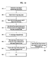
- FIG. 14 is a flowchart illustrating an example of an automatic alignment method according to another embodiment of the present invention.
- the reflected beam is overlapped on the transmitted beam more precisely than in the automatic alignment method shown in FIG. 13 .
- the projector may start to emit an alignment image in order to efficiently perform an automatic alignment function ( 1401 ).
- the alignment image may be a circular alignment image or a cross-shaped alignment image.
- the camera may capture an alignment image ( 1402 ), and the center of a transmitted beam may be found from the captured image in the same manner as in FIG. 13 ( 1403 to 1405 ).
- the center of a transmitted beam may be found from the captured image in the same manner as in FIG. 13 ( 1403 to 1405 ).
- light surrounding the alignment image may be moved to acquire a correct pixel image ( 1403 )
- a reflected beam may be moved upward and downward or leftward and rightward relative to the alignment image to find the center of the transmitted beam ( 1404 )
- a center image of the transmitted beam may be fixed ( 1405 ).
- the angle of the transmitted beam may be adjusted after finding the center of the transmitted beam or before finding the center of the transmitted beam.
- a center image of the reflected beam may be moved to overlap the center image of the reflected beam on the center image of the transmitted beam ( 1406 ), and the center image of the reflected beam may be compared with the center image of the transmitted beam ( 1407 ).
- Steps 1406 and 1407 may be repeatedly carried out until the center image of the reflected beam completely overlaps the center image of the transmitted beam.
- the stereoscopic image may be accurately aligned ( 1409 ).
Landscapes
- Engineering & Computer Science (AREA)
- Multimedia (AREA)
- Signal Processing (AREA)
- Physics & Mathematics (AREA)
- Human Computer Interaction (AREA)
- General Physics & Mathematics (AREA)
- Optics & Photonics (AREA)
- Testing, Inspecting, Measuring Of Stereoscopic Televisions And Televisions (AREA)
- Stereoscopic And Panoramic Photography (AREA)
- Projection Apparatus (AREA)
- Controls And Circuits For Display Device (AREA)
Priority Applications (2)
| Application Number | Priority Date | Filing Date | Title |
|---|---|---|---|
| US15/945,633 US11223819B2 (en) | 2015-04-06 | 2018-04-04 | Stereoscopic image display apparatus with alignment function and method of displaying stereoscopic image using the same |
| US17/546,349 US11575880B2 (en) | 2015-04-06 | 2021-12-09 | Stereoscopic image display apparatus with alignment function and method of displaying stereoscopic image using the same |
Applications Claiming Priority (2)
| Application Number | Priority Date | Filing Date | Title |
|---|---|---|---|
| KR10-2015-0048228 | 2015-04-06 | ||
| KR1020150048228A KR101702024B1 (ko) | 2015-04-06 | 2015-04-06 | 원격정렬형 입체영상장치 및 이를 이용한 입체영상상영방법 |
Related Child Applications (1)
| Application Number | Title | Priority Date | Filing Date |
|---|---|---|---|
| US15/945,633 Continuation US11223819B2 (en) | 2015-04-06 | 2018-04-04 | Stereoscopic image display apparatus with alignment function and method of displaying stereoscopic image using the same |
Publications (2)
| Publication Number | Publication Date |
|---|---|
| US20160295201A1 US20160295201A1 (en) | 2016-10-06 |
| US9942538B2 true US9942538B2 (en) | 2018-04-10 |
Family
ID=55409714
Family Applications (3)
| Application Number | Title | Priority Date | Filing Date |
|---|---|---|---|
| US15/047,630 Active US9942538B2 (en) | 2015-04-06 | 2016-02-19 | Stereoscopic image display apparatus with remotely controlled alignment function and method of displaying stereoscopic image using the same |
| US15/945,633 Active US11223819B2 (en) | 2015-04-06 | 2018-04-04 | Stereoscopic image display apparatus with alignment function and method of displaying stereoscopic image using the same |
| US17/546,349 Active US11575880B2 (en) | 2015-04-06 | 2021-12-09 | Stereoscopic image display apparatus with alignment function and method of displaying stereoscopic image using the same |
Family Applications After (2)
| Application Number | Title | Priority Date | Filing Date |
|---|---|---|---|
| US15/945,633 Active US11223819B2 (en) | 2015-04-06 | 2018-04-04 | Stereoscopic image display apparatus with alignment function and method of displaying stereoscopic image using the same |
| US17/546,349 Active US11575880B2 (en) | 2015-04-06 | 2021-12-09 | Stereoscopic image display apparatus with alignment function and method of displaying stereoscopic image using the same |
Country Status (9)
| Country | Link |
|---|---|
| US (3) | US9942538B2 (ko) |
| EP (2) | EP3079362B1 (ko) |
| JP (1) | JP6364435B2 (ko) |
| KR (1) | KR101702024B1 (ko) |
| CN (2) | CN106054399A (ko) |
| AU (1) | AU2016200791B2 (ko) |
| CA (3) | CA3057219A1 (ko) |
| MX (1) | MX359682B (ko) |
| RU (1) | RU2633022C2 (ko) |
Families Citing this family (14)
| Publication number | Priority date | Publication date | Assignee | Title |
|---|---|---|---|---|
| CN104880906A (zh) * | 2015-06-23 | 2015-09-02 | 深圳市时代华影科技股份有限公司 | 一种可进行图像自动校正的高光效3d系统 |
| KR101641479B1 (ko) * | 2016-03-24 | 2016-07-20 | 김상수 | 입체 영상 디스플레이 장치 |
| WO2018102582A1 (en) * | 2016-12-01 | 2018-06-07 | Magic Leap, Inc. | Projector with scanning array light engine |
| KR20180092054A (ko) * | 2017-02-08 | 2018-08-17 | 유 킴 훙 | 입체 영상 제공 |
| US10904514B2 (en) | 2017-02-09 | 2021-01-26 | Facebook Technologies, Llc | Polarization illumination using acousto-optic structured light in 3D depth sensing |
| US10613413B1 (en) | 2017-05-31 | 2020-04-07 | Facebook Technologies, Llc | Ultra-wide field-of-view scanning devices for depth sensing |
| US10181200B1 (en) * | 2017-06-28 | 2019-01-15 | Facebook Technologies, Llc | Circularly polarized illumination and detection for depth sensing |
| WO2019035494A1 (ko) * | 2017-08-16 | 2019-02-21 | 주식회사 시네마이스터 | 2분할 디지털 시네마의 상영 방법 및 장치 |
| CN107367895A (zh) * | 2017-08-22 | 2017-11-21 | 深圳市乐视环球科技有限公司 | 一种自动调节立体投影装置位置的装置和方法 |
| CN107315315B (zh) * | 2017-08-28 | 2020-08-28 | 北京铂石空间科技有限公司 | 图像对准装置及投影设备 |
| US10574973B2 (en) | 2017-09-06 | 2020-02-25 | Facebook Technologies, Llc | Non-mechanical beam steering for depth sensing |
| CN107920238A (zh) * | 2017-11-03 | 2018-04-17 | 北京铂石空间科技有限公司 | 图像校正装置、图像校正方法及投影设备 |
| CN109282968B (zh) * | 2018-11-09 | 2024-03-08 | 深圳市优威视讯科技股份有限公司 | 一种狩猎相机启动时间的测量装置及测量方法 |
| TR201819689A2 (tr) | 2018-12-18 | 2020-07-21 | Arcelik As | Bi̇r görüntülüme yöntemi̇ |
Citations (14)
| Publication number | Priority date | Publication date | Assignee | Title |
|---|---|---|---|---|
| JPH07333557A (ja) | 1994-06-09 | 1995-12-22 | Sony Corp | 画像投影装置 |
| US20070188603A1 (en) | 2005-10-21 | 2007-08-16 | Riederer Thomas P | Stereoscopic display cart and system |
| WO2008048494A2 (en) | 2006-10-18 | 2008-04-24 | Real D | Combining p and s rays for bright stereoscopic projection |
| US20080246781A1 (en) * | 2007-03-15 | 2008-10-09 | Scalable Display Technologies, Inc. | System and method for providing improved display quality by display adjustment and image processing using optical feedback |
| KR20090094224A (ko) | 2006-09-29 | 2009-09-04 | 컬러링크, 인크. | 입체 투사를 위한 편광 변환 시스템들 |
| DE102008043153A1 (de) | 2008-10-24 | 2010-04-29 | Robert Bosch Gmbh | Verfahren zur Erzeugung eines Bildes sowie Projektor und Mobiltelefon mit einem Projektor |
| JP2010276710A (ja) | 2009-05-26 | 2010-12-09 | Institute Of National Colleges Of Technology Japan | 立体映像投影装置および方法 |
| JP2013003327A (ja) | 2011-06-16 | 2013-01-07 | Seiko Epson Corp | 表示システム、携帯端末、プログラム、表示装置、及び、表示装置の制御方法 |
| JP2013020199A (ja) | 2011-07-14 | 2013-01-31 | Seiko Epson Corp | プロジェクションシステム、画像供給装置、プロジェクター、及び、画像投射方法 |
| US20130321781A1 (en) * | 2012-06-04 | 2013-12-05 | Seiko Epson Corporation | Projector and control method for the projector |
| US20140022192A1 (en) * | 2012-07-18 | 2014-01-23 | Sony Mobile Communications, Inc. | Mobile client device, operation method, recording medium, and operation system |
| JP2014052930A (ja) | 2012-09-10 | 2014-03-20 | Seiko Epson Corp | 表示装置、および、表示装置の制御方法 |
| KR101387097B1 (ko) | 2013-04-02 | 2014-04-29 | 유한회사 마스터이미지쓰리디아시아 | 삼중 광분할 방법과 이를 이용한 입체 영상장치 |
| US20140293416A1 (en) * | 2013-03-26 | 2014-10-02 | Lightspeed Design, Inc. | Stereoscopic Light Recycling Device |
Family Cites Families (40)
| Publication number | Priority date | Publication date | Assignee | Title |
|---|---|---|---|---|
| SU1182471A1 (ru) | 1983-05-19 | 1985-09-30 | Киевский Ордена Ленина Политехнический Институт Им.50-Летия Великой Октябрьской Социалистической Революции | Проекционное стереоскопическое устройство |
| DE69025924T2 (de) | 1989-12-26 | 1996-11-14 | Mitsubishi Rayon Co | Optische vorrichtung zur erzeugung polarisierten lichtes |
| US5225861A (en) | 1991-01-18 | 1993-07-06 | Mortimer Marks | Apparatus for projection of three-dimensional images |
| US5381278A (en) | 1991-05-07 | 1995-01-10 | Canon Kabushiki Kaisha | Polarization conversion unit, polarization illumination apparatus provided with the unit, and projector provided with the apparatus |
| JPH05203894A (ja) | 1992-01-27 | 1993-08-13 | Fujitsu General Ltd | ライトバルブを用いた表示装置 |
| JPH05241103A (ja) | 1992-02-21 | 1993-09-21 | Nec Corp | 投射型液晶表示装置 |
| JP3384026B2 (ja) | 1993-05-10 | 2003-03-10 | セイコーエプソン株式会社 | ディスプレイ装置 |
| JPH078511A (ja) | 1993-06-24 | 1995-01-13 | Nikon Corp | インプラント及びその製造方法 |
| JPH07146474A (ja) | 1993-11-22 | 1995-06-06 | Nec Corp | 投射型液晶表示装置の偏光変換光学系 |
| US5982538A (en) | 1994-01-28 | 1999-11-09 | Mitsubishi Denki Kabushiki Kaisha | Stereoscopic image projection apparatus and telecentric zoom lens |
| JPH07239473A (ja) | 1994-02-28 | 1995-09-12 | Nec Corp | 投写型液晶表示装置 |
| US5729306A (en) | 1994-09-30 | 1998-03-17 | Sharp Kabushiki Kaisha | Light splitting and synthesizing device and liquid crystal display apparatus including the same |
| KR0164463B1 (ko) | 1994-11-25 | 1999-03-20 | 이헌조 | 액정프로젝트의 광학장치 |
| JP2768328B2 (ja) | 1995-10-25 | 1998-06-25 | 日本電気株式会社 | 映像投射装置 |
| JPH1078511A (ja) | 1996-09-04 | 1998-03-24 | Hitachi Ltd | 偏光分離器、偏光変換素子およびそれを用いた液晶表示装置 |
| US6912074B1 (en) | 2004-08-04 | 2005-06-28 | Industry-University Cooperation Foundation Hanyang University | Method of producing a big size holographic projection screen for displaying a three-dimensional color images without color deterioration |
| US7559653B2 (en) * | 2005-12-14 | 2009-07-14 | Eastman Kodak Company | Stereoscopic display apparatus using LCD panel |
| CN100507706C (zh) | 2006-02-13 | 2009-07-01 | 深圳雅图数字视频技术有限公司 | Lcd立体投影机偏振管理系统 |
| CN101398536B (zh) * | 2007-09-24 | 2011-05-04 | 鸿富锦精密工业(深圳)有限公司 | 立体投影光学系统 |
| CN101408675B (zh) | 2007-10-09 | 2010-06-09 | 鸿富锦精密工业(深圳)有限公司 | 立体投影光学系统 |
| WO2009111066A1 (en) | 2008-03-06 | 2009-09-11 | Halozyme, Inc. | Large-scale production of soluble hyaluronidase |
| JP5223452B2 (ja) * | 2008-05-20 | 2013-06-26 | 株式会社リコー | プロジェクタ及び投影画像形成方法及び車両用ヘッドアップディスプレイ装置 |
| JP5217823B2 (ja) | 2008-09-17 | 2013-06-19 | 株式会社ニコン | プロジェクタ装置 |
| CN101702072B (zh) | 2008-11-06 | 2011-03-23 | 上海丽恒光微电子科技有限公司 | 光投影引擎设备 |
| JP5391662B2 (ja) | 2008-11-21 | 2014-01-15 | ソニー株式会社 | 立体画像表示装置、偏光分離合成装置、立体画像表示方法 |
| CN102301275B (zh) | 2008-12-01 | 2014-10-08 | 瑞尔D股份有限公司 | 用于在中间像面使用空间复用的立体投影系统和方法 |
| JP5434085B2 (ja) | 2009-01-16 | 2014-03-05 | ソニー株式会社 | 投射型画像表示装置および投射光学系 |
| JP2011022530A (ja) * | 2009-07-21 | 2011-02-03 | Fujifilm Corp | プロジェクタ |
| US8842222B2 (en) * | 2010-04-18 | 2014-09-23 | Imax Corporation | Double stacked projection |
| EP2572231A2 (en) | 2010-05-19 | 2013-03-27 | 3M Innovative Properties Company | Fly eye integrator polarization converter |
| US8721083B2 (en) | 2010-09-07 | 2014-05-13 | Delta Electronics, Inc. | Polarization conversion system and stereoscopic projection system employing same |
| JP5658970B2 (ja) * | 2010-10-20 | 2015-01-28 | 株式会社ミツバ | ドアミラー |
| CN202256840U (zh) * | 2011-06-16 | 2012-05-30 | 山东电力集团公司济南供电公司 | 多角度遥控反光镜 |
| CN202182966U (zh) * | 2011-08-29 | 2012-04-04 | 刘小君 | 一种电视卧视镜 |
| CN103728821B (zh) | 2012-10-12 | 2015-10-28 | 扬明光学股份有限公司 | 投影装置 |
| CN105324702A (zh) * | 2013-05-29 | 2016-02-10 | Volfoni研发公司 | 用于立体图像投影仪的光学偏振装置 |
| FR3000232B1 (fr) * | 2013-05-29 | 2019-07-26 | Volfoni R&D | Dispositif de polarisation optique pour un projecteur d'images stereoscopiques |
| CN203405635U (zh) | 2013-09-05 | 2014-01-22 | 深圳市时代华影科技开发有限公司 | 一种低投射比高光效立体投影装置及立体投影系统 |
| CN103529637B (zh) * | 2013-10-29 | 2016-04-13 | 王高胜 | 3d影视系统及3d投影方法 |
| CN104865778A (zh) * | 2014-02-24 | 2015-08-26 | 联想(北京)有限公司 | 一种投影装置及电子设备 |
-
2015
- 2015-04-06 KR KR1020150048228A patent/KR101702024B1/ko active IP Right Grant
-
2016
- 2016-02-08 AU AU2016200791A patent/AU2016200791B2/en active Active
- 2016-02-09 CA CA3057219A patent/CA3057219A1/en active Pending
- 2016-02-09 CA CA2920266A patent/CA2920266C/en active Active
- 2016-02-09 CA CA3235707A patent/CA3235707A1/en active Pending
- 2016-02-12 EP EP16155506.5A patent/EP3079362B1/en active Active
- 2016-02-12 EP EP21183307.4A patent/EP3917139A1/en active Pending
- 2016-02-19 US US15/047,630 patent/US9942538B2/en active Active
- 2016-03-14 JP JP2016049357A patent/JP6364435B2/ja active Active
- 2016-03-22 CN CN201610164237.2A patent/CN106054399A/zh active Pending
- 2016-03-22 CN CN202211256389.7A patent/CN115657331A/zh active Pending
- 2016-03-24 RU RU2016110777A patent/RU2633022C2/ru active
- 2016-04-05 MX MX2016004343A patent/MX359682B/es active IP Right Grant
-
2018
- 2018-04-04 US US15/945,633 patent/US11223819B2/en active Active
-
2021
- 2021-12-09 US US17/546,349 patent/US11575880B2/en active Active
Patent Citations (16)
| Publication number | Priority date | Publication date | Assignee | Title |
|---|---|---|---|---|
| JPH07333557A (ja) | 1994-06-09 | 1995-12-22 | Sony Corp | 画像投影装置 |
| US20070188603A1 (en) | 2005-10-21 | 2007-08-16 | Riederer Thomas P | Stereoscopic display cart and system |
| KR20090094224A (ko) | 2006-09-29 | 2009-09-04 | 컬러링크, 인크. | 입체 투사를 위한 편광 변환 시스템들 |
| WO2008048494A2 (en) | 2006-10-18 | 2008-04-24 | Real D | Combining p and s rays for bright stereoscopic projection |
| US20080143965A1 (en) * | 2006-10-18 | 2008-06-19 | Real D | Combining P and S rays for bright stereoscopic projection |
| US20080246781A1 (en) * | 2007-03-15 | 2008-10-09 | Scalable Display Technologies, Inc. | System and method for providing improved display quality by display adjustment and image processing using optical feedback |
| DE102008043153A1 (de) | 2008-10-24 | 2010-04-29 | Robert Bosch Gmbh | Verfahren zur Erzeugung eines Bildes sowie Projektor und Mobiltelefon mit einem Projektor |
| JP2010276710A (ja) | 2009-05-26 | 2010-12-09 | Institute Of National Colleges Of Technology Japan | 立体映像投影装置および方法 |
| JP2013003327A (ja) | 2011-06-16 | 2013-01-07 | Seiko Epson Corp | 表示システム、携帯端末、プログラム、表示装置、及び、表示装置の制御方法 |
| JP2013020199A (ja) | 2011-07-14 | 2013-01-31 | Seiko Epson Corp | プロジェクションシステム、画像供給装置、プロジェクター、及び、画像投射方法 |
| US20130321781A1 (en) * | 2012-06-04 | 2013-12-05 | Seiko Epson Corporation | Projector and control method for the projector |
| US20140022192A1 (en) * | 2012-07-18 | 2014-01-23 | Sony Mobile Communications, Inc. | Mobile client device, operation method, recording medium, and operation system |
| JP2014052930A (ja) | 2012-09-10 | 2014-03-20 | Seiko Epson Corp | 表示装置、および、表示装置の制御方法 |
| US20140293416A1 (en) * | 2013-03-26 | 2014-10-02 | Lightspeed Design, Inc. | Stereoscopic Light Recycling Device |
| KR101387097B1 (ko) | 2013-04-02 | 2014-04-29 | 유한회사 마스터이미지쓰리디아시아 | 삼중 광분할 방법과 이를 이용한 입체 영상장치 |
| WO2014163322A1 (ko) | 2013-04-02 | 2014-10-09 | 유한회사 마스터이미지쓰리디아시아 | 입체 영상 장치 |
Non-Patent Citations (2)
| Title |
|---|
| European Search Report in Appln. No. 16155506.5 dated Jun. 9, 2016. |
| Masterimage3d: "Installation & Operation Manual; HORIZON3D & HORIZON3D S 55 HORIZON3D&HORIZON3D S Digital 3D Cinema System Installation & Operation Manual", Jul. 14, 2014, pp. 1-67, XP055276940. |
Also Published As
| Publication number | Publication date |
|---|---|
| US20190014311A1 (en) | 2019-01-10 |
| KR101702024B1 (ko) | 2017-02-02 |
| CA2920266A1 (en) | 2016-10-06 |
| RU2016110777A (ru) | 2017-09-28 |
| JP2016197232A (ja) | 2016-11-24 |
| CA3235707A1 (en) | 2016-10-06 |
| CA3057219A1 (en) | 2016-10-06 |
| AU2016200791B2 (en) | 2017-04-20 |
| CN115657331A (zh) | 2023-01-31 |
| BR102016007570A2 (pt) | 2016-10-11 |
| CA2920266C (en) | 2020-05-26 |
| JP6364435B2 (ja) | 2018-07-25 |
| KR20160119495A (ko) | 2016-10-14 |
| AU2016200791A1 (en) | 2016-10-20 |
| EP3079362A1 (en) | 2016-10-12 |
| EP3917139A1 (en) | 2021-12-01 |
| EP3079362B1 (en) | 2021-07-07 |
| MX359682B (es) | 2018-10-05 |
| US20160295201A1 (en) | 2016-10-06 |
| CN106054399A (zh) | 2016-10-26 |
| MX2016004343A (es) | 2016-10-05 |
| US11575880B2 (en) | 2023-02-07 |
| RU2633022C2 (ru) | 2017-10-11 |
| US11223819B2 (en) | 2022-01-11 |
| US20220174264A1 (en) | 2022-06-02 |
Similar Documents
| Publication | Publication Date | Title |
|---|---|---|
| US11575880B2 (en) | Stereoscopic image display apparatus with alignment function and method of displaying stereoscopic image using the same | |
| US9664376B2 (en) | Projection-type image display apparatus | |
| JP2017092795A (ja) | 画像投射システム、プロジェクター、及び、画像投射システムの制御方法 | |
| US9282301B1 (en) | System for image projection | |
| US20180077346A1 (en) | Display apparatus, method of controlling display apparatus, document camera, and method of controlling document camera | |
| US20090103051A1 (en) | Stereo projection optical system | |
| JP6191019B2 (ja) | 投影装置及び投影方法 | |
| JP6631014B2 (ja) | 表示システム、及び表示制御方法 | |
| US20120057138A1 (en) | Projection display apparatus | |
| CN206757203U (zh) | 图像投影处理设备 | |
| CN108983427A (zh) | 图像投影处理设备及图像投影处理方法 | |
| KR100659327B1 (ko) | 입체 영상 투영장치 | |
| US20220307821A1 (en) | Detection apparatus, detection method, and spatial projection apparatus | |
| BR102016007570B1 (pt) | Aparelho de exibição de imagem estereoscópica com função de alinhamento remotamente controlada e método de exibir imagem estereoscópica usando o mesmo | |
| US11789567B2 (en) | Detection apparatus, detection method, and spatial projection apparatus | |
| JP2015201771A (ja) | 投射型表示装置および制御方法 | |
| RU138095U1 (ru) | Система преобразования поляризации для стереоскопической проекции | |
| KR20150136157A (ko) | 무안경식 입체 영상 디스플레이장치 | |
| KR20090023844A (ko) | 프로젝터 및 이를 위한 동작 제어 방법 | |
| KR200356804Y1 (ko) | 입체 영상 투영장치 | |
| JP2015204487A (ja) | 投影システム |
Legal Events
| Date | Code | Title | Description |
|---|---|---|---|
| AS | Assignment |
Owner name: MASTERIMAGE 3D ASIA, LLC., KOREA, REPUBLIC OF Free format text: ASSIGNMENT OF ASSIGNORS INTEREST;ASSIGNORS:SO, BONG JAE;KIM, YONG KYU;KIM, YOUNG SUK;REEL/FRAME:037771/0762 Effective date: 20160215 |
|
| AS | Assignment |
Owner name: REALD INC., CALIFORNIA Free format text: ASSIGNMENT OF ASSIGNORS INTEREST;ASSIGNOR:MASTERIMAGE3D ASIA, LLC;REEL/FRAME:042041/0622 Effective date: 20170223 |
|
| STCF | Information on status: patent grant |
Free format text: PATENTED CASE |
|
| AS | Assignment |
Owner name: JEFFERIES FINANCE LLC, AS COLLATERAL AGENT, NEW YORK Free format text: SECURITY INTEREST;ASSIGNORS:REALD INC.;RHOMBUS INTERMEDIATE HOLDINGS, LP;REALD HOLDINGS, INC;AND OTHERS;REEL/FRAME:047723/0767 Effective date: 20181130 Owner name: JEFFERIES FINANCE LLC, AS COLLATERAL AGENT, NEW YO Free format text: SECURITY INTEREST;ASSIGNORS:REALD INC.;RHOMBUS INTERMEDIATE HOLDINGS, LP;REALD HOLDINGS, INC;AND OTHERS;REEL/FRAME:047723/0767 Effective date: 20181130 |
|
| AS | Assignment |
Owner name: JEFFERIES FINANCE LLC, AS COLLATERAL AGENT, NEW YORK Free format text: SECURITY INTEREST;ASSIGNORS:REALD INC.;RHOMBUS INTERMEDIATE HOLDINGS, LP;REALD HOLDINGS, INC;AND OTHERS;REEL/FRAME:047740/0085 Effective date: 20181130 Owner name: JEFFERIES FINANCE LLC, AS COLLATERAL AGENT, NEW YO Free format text: SECURITY INTEREST;ASSIGNORS:REALD INC.;RHOMBUS INTERMEDIATE HOLDINGS, LP;REALD HOLDINGS, INC;AND OTHERS;REEL/FRAME:047740/0085 Effective date: 20181130 |
|
| FEPP | Fee payment procedure |
Free format text: ENTITY STATUS SET TO UNDISCOUNTED (ORIGINAL EVENT CODE: BIG.); ENTITY STATUS OF PATENT OWNER: LARGE ENTITY |
|
| FEPP | Fee payment procedure |
Free format text: PETITION RELATED TO MAINTENANCE FEES GRANTED (ORIGINAL EVENT CODE: PTGR); ENTITY STATUS OF PATENT OWNER: LARGE ENTITY |
|
| AS | Assignment |
Owner name: CORTLAND CAPITAL MARKET SERVICES LLC, AS THE SUCCESSOR COLLATERAL AGENT, ILLINOIS Free format text: ASSIGNMENT OF SECURITY INTEREST IN COLLATERAL;ASSIGNOR:JEFFERIES FINANCE LLC, AS COLLATERAL AGENT;REEL/FRAME:052623/0086 Effective date: 20200506 Owner name: HPS INVESTMENT PARTNERS, LLC, AS THE SUCCESSOR-IN-INTEREST, NEW YORK Free format text: SECURITY INTEREST;ASSIGNOR:JEFFERIES FINANCE LLC, AS COLLATERAL AGENT;REEL/FRAME:052622/0104 Effective date: 20200506 |
|
| AS | Assignment |
Owner name: REALD INC., CALIFORNIA Free format text: RELEASE OF SECURITY INTEREST RECORDED AT REEL/FRAME 047740/0085;ASSIGNOR:CORTLAND CAPITAL MARKET SERVICES, LLC;REEL/FRAME:054593/0247 Effective date: 20201120 Owner name: REALD DDMG ACQUISITION, LLC, CALIFORNIA Free format text: RELEASE OF SECURITY INTEREST RECORDED AT REEL/FRAME 047740/0085;ASSIGNOR:CORTLAND CAPITAL MARKET SERVICES, LLC;REEL/FRAME:054593/0247 Effective date: 20201120 Owner name: COLORLINK, INC., CALIFORNIA Free format text: RELEASE OF SECURITY INTEREST RECORDED AT REEL/FRAME 047740/0085;ASSIGNOR:CORTLAND CAPITAL MARKET SERVICES, LLC;REEL/FRAME:054593/0247 Effective date: 20201120 Owner name: RHOMBUS INTERMEDIATE HOLDINGS, LP, CALIFORNIA Free format text: RELEASE OF SECURITY INTEREST RECORDED AT REEL/FRAME 047740/0085;ASSIGNOR:CORTLAND CAPITAL MARKET SERVICES, LLC;REEL/FRAME:054593/0247 Effective date: 20201120 Owner name: REALD SPARK, LLC, CALIFORNIA Free format text: RELEASE OF SECURITY INTEREST RECORDED AT REEL/FRAME 047740/0085;ASSIGNOR:CORTLAND CAPITAL MARKET SERVICES, LLC;REEL/FRAME:054593/0247 Effective date: 20201120 |
|
| MAFP | Maintenance fee payment |
Free format text: PAYMENT OF MAINTENANCE FEE, 4TH YEAR, LARGE ENTITY (ORIGINAL EVENT CODE: M1551); ENTITY STATUS OF PATENT OWNER: LARGE ENTITY Year of fee payment: 4 |