US9933743B2 - Recording material processing apparatus including alignment unit for aligning recording materials and image forming apparatus - Google Patents
Recording material processing apparatus including alignment unit for aligning recording materials and image forming apparatus Download PDFInfo
- Publication number
- US9933743B2 US9933743B2 US14/967,681 US201514967681A US9933743B2 US 9933743 B2 US9933743 B2 US 9933743B2 US 201514967681 A US201514967681 A US 201514967681A US 9933743 B2 US9933743 B2 US 9933743B2
- Authority
- US
- United States
- Prior art keywords
- recording material
- unit
- control
- alignment
- alignment member
- Prior art date
- Legal status (The legal status is an assumption and is not a legal conclusion. Google has not performed a legal analysis and makes no representation as to the accuracy of the status listed.)
- Active
Links
Images


Classifications
-
- G—PHYSICS
- G03—PHOTOGRAPHY; CINEMATOGRAPHY; ANALOGOUS TECHNIQUES USING WAVES OTHER THAN OPTICAL WAVES; ELECTROGRAPHY; HOLOGRAPHY
- G03G—ELECTROGRAPHY; ELECTROPHOTOGRAPHY; MAGNETOGRAPHY
- G03G15/00—Apparatus for electrographic processes using a charge pattern
- G03G15/65—Apparatus which relate to the handling of copy material
- G03G15/6538—Devices for collating sheet copy material, e.g. sorters, control, copies in staples form
-
- B—PERFORMING OPERATIONS; TRANSPORTING
- B65—CONVEYING; PACKING; STORING; HANDLING THIN OR FILAMENTARY MATERIAL
- B65H—HANDLING THIN OR FILAMENTARY MATERIAL, e.g. SHEETS, WEBS, CABLES
- B65H31/00—Pile receivers
- B65H31/02—Pile receivers with stationary end support against which pile accumulates
-
- B—PERFORMING OPERATIONS; TRANSPORTING
- B65—CONVEYING; PACKING; STORING; HANDLING THIN OR FILAMENTARY MATERIAL
- B65H—HANDLING THIN OR FILAMENTARY MATERIAL, e.g. SHEETS, WEBS, CABLES
- B65H31/00—Pile receivers
- B65H31/24—Pile receivers multiple or compartmented, e.d. for alternate, programmed, or selective filling
-
- B—PERFORMING OPERATIONS; TRANSPORTING
- B65—CONVEYING; PACKING; STORING; HANDLING THIN OR FILAMENTARY MATERIAL
- B65H—HANDLING THIN OR FILAMENTARY MATERIAL, e.g. SHEETS, WEBS, CABLES
- B65H31/00—Pile receivers
- B65H31/30—Arrangements for removing completed piles
- B65H31/3009—Arrangements for removing completed piles by dropping, e.g. removing the pile support from under the pile
- B65H31/3018—Arrangements for removing completed piles by dropping, e.g. removing the pile support from under the pile from opposite part-support elements, e.g. operated simultaneously
-
- B—PERFORMING OPERATIONS; TRANSPORTING
- B65—CONVEYING; PACKING; STORING; HANDLING THIN OR FILAMENTARY MATERIAL
- B65H—HANDLING THIN OR FILAMENTARY MATERIAL, e.g. SHEETS, WEBS, CABLES
- B65H31/00—Pile receivers
- B65H31/34—Apparatus for squaring-up piled articles
- B65H31/36—Auxiliary devices for contacting each article with a front stop as it is piled
-
- B—PERFORMING OPERATIONS; TRANSPORTING
- B65—CONVEYING; PACKING; STORING; HANDLING THIN OR FILAMENTARY MATERIAL
- B65H—HANDLING THIN OR FILAMENTARY MATERIAL, e.g. SHEETS, WEBS, CABLES
- B65H31/00—Pile receivers
- B65H31/34—Apparatus for squaring-up piled articles
- B65H31/38—Apparatus for vibrating or knocking the pile during piling
-
- B—PERFORMING OPERATIONS; TRANSPORTING
- B65—CONVEYING; PACKING; STORING; HANDLING THIN OR FILAMENTARY MATERIAL
- B65H—HANDLING THIN OR FILAMENTARY MATERIAL, e.g. SHEETS, WEBS, CABLES
- B65H43/00—Use of control, checking, or safety devices, e.g. automatic devices comprising an element for sensing a variable
- B65H43/06—Use of control, checking, or safety devices, e.g. automatic devices comprising an element for sensing a variable detecting, or responding to, completion of pile
-
- B—PERFORMING OPERATIONS; TRANSPORTING
- B65—CONVEYING; PACKING; STORING; HANDLING THIN OR FILAMENTARY MATERIAL
- B65H—HANDLING THIN OR FILAMENTARY MATERIAL, e.g. SHEETS, WEBS, CABLES
- B65H2301/00—Handling processes for sheets or webs
- B65H2301/40—Type of handling process
- B65H2301/42—Piling, depiling, handling piles
- B65H2301/421—Forming a pile
- B65H2301/4212—Forming a pile of articles substantially horizontal
-
- B—PERFORMING OPERATIONS; TRANSPORTING
- B65—CONVEYING; PACKING; STORING; HANDLING THIN OR FILAMENTARY MATERIAL
- B65H—HANDLING THIN OR FILAMENTARY MATERIAL, e.g. SHEETS, WEBS, CABLES
- B65H2301/00—Handling processes for sheets or webs
- B65H2301/40—Type of handling process
- B65H2301/42—Piling, depiling, handling piles
- B65H2301/421—Forming a pile
- B65H2301/4213—Forming a pile of a limited number of articles, e.g. buffering, forming bundles
-
- B—PERFORMING OPERATIONS; TRANSPORTING
- B65—CONVEYING; PACKING; STORING; HANDLING THIN OR FILAMENTARY MATERIAL
- B65H—HANDLING THIN OR FILAMENTARY MATERIAL, e.g. SHEETS, WEBS, CABLES
- B65H2405/00—Parts for holding the handled material
- B65H2405/30—Other features of supports for sheets
- B65H2405/33—Compartmented support
- B65H2405/332—Superposed compartments
-
- B—PERFORMING OPERATIONS; TRANSPORTING
- B65—CONVEYING; PACKING; STORING; HANDLING THIN OR FILAMENTARY MATERIAL
- B65H—HANDLING THIN OR FILAMENTARY MATERIAL, e.g. SHEETS, WEBS, CABLES
- B65H2801/00—Application field
- B65H2801/03—Image reproduction devices
- B65H2801/06—Office-type machines, e.g. photocopiers
Definitions
- the present invention relates to a recording material processing apparatus that performs offset processing on recording materials and an image forming apparatus provided with the recording material processing apparatus.
- an image forming apparatus which has a recording material processing apparatus capable of performing offset processing on a recording material and discharging the recording material.
- a recording material processing apparatus receives and stacks a recording material on which an image has been formed, bundles one or more stacked recording materials into a single bundle using an alignment member, and discharges the bundled recording materials by shifting each bundle.
- Japanese Patent Laid-Open No. 2013-230891 discloses an arrangement in which offset processing is performed by two alignment members having different driving sources.
- Japanese Patent Laid-Open No. 2000-143082 also discloses an arrangement in which offset processing is performed by shifting a bundle after aligning the recording materials by an alignment member.
- the cost of the arrangement of the Japanese Patent Laid-Open No. 2013-230891 increases since a driving source is provided in each of the two alignment members.
- the throughput decreases in an arrangement in which the bundle is shifted after aligning the recording materials by the alignment members since it becomes necessary to create an interval between the recording materials for each bundle shift operation.
- Japanese Patent Laid-Open No. 2000-143082 discloses a buffer roller provided to prevent this decrease in throughput, the cost increases due to the provision of the buffer roller.
- a recording material processing apparatus includes: a first stacking unit configured to stack a recording material; a second stacking unit provided on a downstream side of the first stacking unit in a conveyance direction of the recording material; an alignment unit configured to align the recording material stacked in the first stacking unit before the recording material is discharged to the second stacking unit; and a control unit configured to perform control of discharging the recording material to the second stacking unit by switching between first control not to align the recording material by the alignment unit and second control to align the recording material by the alignment unit.
- FIG. 1 is a view showing the arrangement of an image forming apparatus according to an embodiment
- FIG. 2 is a perspective view of a recording material processing apparatus according to an embodiment
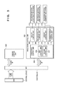
- FIG. 3 is a block diagram showing the control arrangement of the image forming apparatus according to an embodiment
- FIG. 4 is a flowchart showing discharge control according to an embodiment
- FIG. 5 is a flowchart showing first discharge control according to an embodiment
- FIG. 6 is a view showing a state in which recording materials are stacked in an intermediate stacking unit in the first discharge control according to an embodiment
- FIG. 7 is a flowchart showing second discharge control according to an embodiment
- FIG. 8 is a view showing a state in which recording materials are stacked in the intermediate stacking unit in the second discharge control according to an embodiment
- FIG. 9 is an explanatory view for comparing the throughputs of an embodiment and a related art.
- FIG. 10 is a flowchart showing first discharge control according to an embodiment
- FIG. 11 is an explanatory view for comparing the throughputs of embodiments.
- FIG. 12 is a flowchart showing second discharge control according to an embodiment
- FIG. 13 is a view showing a state in which recording materials are stacked in an intermediate stacking unit in discharge control according to an embodiment.
- FIG. 14 is an explanatory view for comparing the throughputs of embodiments.
- FIG. 1 is a view showing the arrangement of an image forming apparatus 100 which includes a recording material processing apparatus 200 .
- a photosensitive member 111 When forming an image, a photosensitive member 111 is rotated clockwise in FIG. 1 .
- a charging roller 112 charges the surface of the photosensitive member 111 to have a uniform potential.
- An exposure unit 113 scans and exposes the photosensitive member 111 with light to form an electrostatic latent image.
- a developing unit 114 outputs a developing bias to develop the electrostatic latent image of the photosensitive member 111 by toner and visualizes the image as a toner image.
- Rollers 107 feed each recording material stored in a cassette 105 onto a conveyance path 109 .
- the recording material is conveyed toward the nip region of the photosensitive member 111 and a transfer roller 115 by rollers provided along the conveyance path.
- the transfer roller 115 outputs a transfer bias to transfer the toner image of the photosensitive member 111 onto the recording material.
- a fixing unit 103 fixes the toner image transferred onto the recording material on the recording material.
- a switching member 120 is provided in order to switch between sending the image-formed recording material toward the recording material processing apparatus 200 and discharging the recording material to a discharge tray 124 . More specifically, the recording material is discharged to the discharge tray 124 by setting the switching member 120 at the position indicated by the solid line, and the recording material is conveyed to the recording material processing apparatus 200 by setting the switching member 120 at the position indicated by the dotted line.
- a conveyance path 126 is provided in order to return the recording material once again to the nip region of the photosensitive member 111 and the transfer roller 115 when forming images on both sides of the recording material.
- Rollers 119 are configured to be rotatable in two directions and convey the recording material to the conveyance path 126 when forming images on both sides of the recording material.
- FIG. 2 is a perspective view of the recording material processing apparatus 200 .
- Rollers 201 convey the recording material conveyed to the recording material processing apparatus 200 along a conveyance path 202 toward rollers 203 .
- An intermediate stacking unit 207 (first stacking unit) is provided on the downstream side of the conveyance direction of the rollers 203 , and a jogger 206 is provided on the downstream side of the intermediate stacking unit 207 .
- the rollers 203 discharge the recording material to the intermediate stacking unit 207 , and the recording material is stacked across the intermediate stacking unit 207 and the jogger 206 .
- the jogger 206 aligns the widthwise direction positions of the plurality of stacked recording materials.
- the widthwise direction is the direction perpendicular to the conveyance direction of the recording material.
- the jogger 206 includes an alignment member 206 a and an alignment member 206 b .
- the alignment members 206 a and 206 b are configured to link and move in the widthwise direction by an alignment motor 402 .
- An alignment paddle 204 is provided on the upstream side of the jogger 206 .
- the alignment paddle 204 aligns the conveyance direction positions of the recording materials stacked in the intermediate stacking unit 207 .
- a binding unit 208 binds the end portions of the recording materials stacked in the intermediate stacking unit 207 .
- a discharge roller 205 is configured so that it can be either set as a state in contact with the recording materials stacked in the intermediate stacking unit 207 or as a state spaced apart from the recording materials.
- the recording materials are stacked in the intermediate stacking unit 207 .
- the discharge roller 205 and the recording materials are spaced apart, and the alignment members 206 a and 206 b are moved by the alignment motor 402 to a position to receive the recording materials. Accordingly, both ends of the recording materials in the widthwise direction are supported by the jogger 206 .
- the alignment paddle 204 performs alignment in the conveyance direction. After the recording materials are aligned, a bundle of recording materials is discharged to the stacking unit 209 by causing the discharger roller 205 to contact the recording materials and rotate.
- FIG. 3 is a view showing the control arrangement of the image forming apparatus 100 .
- a controller 301 of the image forming apparatus 100 receives print data by communicating with an external device 300 such as a host computer or the like.
- the controller 301 determines print conditions from the print data and instructs printing in accordance with the print condition to a printer control unit 302 via a serial I/F.
- the printer control unit 302 controls each mechanism to form and fix an image on the recording material in accordance with the print condition received from the controller 301 .
- the controller 301 designates processing conditions to a processing control unit 303 via the serial I/F.
- the processing control unit 303 is a control unit of the recording material processing apparatus 200 .
- the processing conditions include pieces of information indicating the recording material type, size, number of sheets, presence/absence of offset, and presence/absence of binding processing.
- a conveyance control unit 304 of the processing control unit 303 performs control of conveying and discharging the recording material in the recording material processing apparatus 200 in accordance with the processing conditions received from the controller 301 . More specifically, the conveyance control unit 304 controls a roller control unit 308 which controls a recording material conveyance mechanism 313 including the rollers 201 and rollers 203 to convey the recording material.
- the conveyance control unit 304 controls a jogger control unit 310 and an alignment paddle control unit 311 to align the recording materials.
- the jogger control unit 310 drives the alignment motor 402 , and the alignment paddle control unit 311 drives the alignment paddle 204 .
- a recording material alignment mechanism 315 of FIG. 3 is a general term for members that align the recording materials and include the jogger 206 and the alignment paddle 204 and is also referred to as an alignment unit. Additionally, under the control of the conveyance control unit 304 , a discharge control unit 309 controls a recording material discharge mechanism 314 including the discharge roller 205 to discharge the recording material to the stacking unit 209 . Note that a first control unit 306 and a second control unit 307 of the conveyance control unit 304 will be described later.
- FIG. 4 is a flowchart showing the processing of the conveyance control unit 304 when the offset is performed for each print job.
- the conveyance control unit 304 stands by until it receives a loading notification from the controller 301 .
- the conveyance control unit 304 determines whether recording material alignment was performed in the preceding print job. If alignment was performed in the preceding print job, the first control unit 306 performs the first control in step S 502 . On the other hand, if no alignment was performed in the preceding print job, the second control unit 307 performs the second control in step S 508 . The first control and the second control will be described later.
- step S 503 the conveyance control unit 304 monitors whether there are recording materials on the jogger 206 and ends the processing if no recording materials exist. On the other hand, if recording materials exist, in step S 504 , the conveyance control unit 304 determines whether the recording materials on the jogger 206 have reached the maximum stacking count as a threshold and ends the processing if the maximum stacking count has not been reached. On the other hand, if the maximum stacking count has been reached, in step S 505 , the conveyance control unit 304 drives the discharge roller 205 and discharges the recording materials to the stacking unit 209 . In step S 506 , the conveyance control unit 304 stands by until discharging of the recording materials is completed. When the discharging is completed, the conveyance control unit 304 stops the driving of the discharge roller 205 in step S 507 .
- FIG. 5 is a flowchart of the first control operation.
- the first control represents control of discharging recording materials to the stacking unit 209 without alignment.
- the first control unit 306 obtains the processing conditions in step S 520 and drives the rollers 201 and 203 to convey each recording material toward the intermediate stacking unit 207 in step S 521 . Additionally, in step S 522 , the first control unit 306 moves the jogger 206 to the reception position. In step S 523 , the first control unit 306 stands by until a recording material is stacked on the jogger 206 . When the recording material is stacked, the first control unit 306 determines whether the stacked recording material is the last recording material of the print job.
- the first control unit 306 stops the driving of the rollers 201 and 203 and ends the processing in step S 528 .
- FIG. 6 shows the state at that time, that is, the state when the jogger 206 is stopped at the reception position and unaligned recording materials are stacked in the intermediate stacking unit 207 .
- the first control unit 306 drives the discharge roller 205 to discharge the recording materials to the stacking unit 209 in step S 525 and stands by until discharging is completed in step S 526 .
- the first control unit 306 stops the discharger roller 205 in step S 527 and performs the process of step S 528 .
- FIG. 7 is a flowchart of the second control operation by the second control unit 307 .
- the second control represents control of aligning the recording materials stacked in the intermediate stacking unit 207 by the jogger 206 and discharging the recording materials stacked in the intermediate stacking unit 207 to the stacking unit 209 upon completion of the print job. Since the processes of steps S 540 to S 543 are the same as steps S 520 to S 523 of the first control in FIG. 5 , a repetitive description thereof will be omitted.
- the second control unit 307 When the recording materials are stacked in the jogger 206 in step S 543 , the second control unit 307 performs conveyance direction alignment processing by the alignment paddle 204 in step S 544 and performs widthwise direction alignment processing by the jogger 206 in step S 545 .
- FIG. 8 shows how the aligned recording materials are stacked in the intermediate stacking unit 207 . Since the processes of steps S 546 to S 550 are the same as steps S 524 to S 528 of the first discharge control in FIG. 5 , a repetitive description thereof will be omitted.
- each recording material discharged to the stacking unit 209 in the first control is offset with respect to each recording material discharged to the stacking unit 209 in the second control.
- the first control and the second control are alternately executed for a unit of processing of the recording materials. Therefore, the recording materials discharged to the stacking unit 209 are offset for the unit of processing.
- the unit of processing corresponds to the print job designated by a user, and the controller 301 notifies the recording material processing apparatus 200 of each process as a processing condition. Note that in the second control of FIG.
- the alignment of recording materials is performed each time a recording material that is a target of the second control is stacked in the intermediate stacking unit 207 .
- the timing for aligning the recording materials by the jogger 206 or the like is not limited to this.
- it can be an arrangement in which the plurality of recording materials are stacked in the intermediate stacking unit 207 or an arrangement in which the last recording material of a print job is stacked in the intermediate stacking unit 207 .
- FIG. 9 is a view for comparing the throughput of the offset control of the related art with the throughput of the offset control according to the embodiment. Comparison is made for a case in which two sets of a five-sheet print job have been performed. For example, assume that processing of moving the jogger 206 to the reception position, recording material bundle discharge processing, and bundle shift processing each take 1 second, and that the first control for the five sheets of recording materials and the second control each take 5 seconds. Note that the first control and the second control in this example exclude the processing of moving the jogger 206 to the reception position and the recording material discharge processing. In this case, since the embodiment does not require the bundle shift processing, the processing is completed 2 seconds earlier than the related art. Note that the related art constantly performs alignment and both two sets correspond to the second control.
- a plurality of alignment motors need not be provided in the embodiment. Furthermore, since no bundle shift operation is performed, an interval between recording materials which is necessary for performing bundle shift need not be provided, and the throughput of offset control can be improved.
- FIG. 10 is a flowchart showing the first control according to the embodiment.
- a first control unit 306 obtains processing conditions in step S 600 and conveys each recording material toward the intermediate stacking unit 207 in step S 601 .
- the first control unit 306 drives a discharge roller 205 to discharge the recording materials to the stacking unit 209 and stands by until discharging is completed in step S 603 .
- the first control unit 306 stops the discharge roller 205 in step S 604 , stops the driving of rollers 201 and 203 in step S 605 , and ends the processing. Note that the processing of FIG. 10 is repeated during one print job.
- FIG. 11 is a view for comparing the throughputs of the second embodiment and first embodiment.
- FIG. 11 shows a case in which two sets of a five-sheet print job have been processed.
- processing for moving a jogger 206 to a reception position and recording material bundle discharge processing each take 1 second
- the first control for the five sheets of recording materials and the second control each take 5 seconds.
- the first control and the second control in this example exclude the processing of moving the jogger 206 to the reception position and the recording material discharge processing.
- the processing is completed 2 seconds earlier than that of the first embodiment since the movement of the jogger 206 and the recording material discharge processing as in the first embodiment are not necessary.
- the throughput of offset control can be improved by directly discharging the recording materials to the stacking unit 209 without stacking the recording materials in the intermediate stacking unit 207 in the first control.
- the third embodiment improves both the stackability and throughput.
- the second control of the second embodiment stacked and aligned recording materials in the intermediate stacking unit 207 and discharged a bundle of recording materials to the stacking unit 209 .
- recording materials are not discharged to a stacking unit 209 .
- Recording materials as a target of the succeeding first control are stacked over the recording materials aligned in the preceding second control in an intermediate stacking unit 207 and discharged all together to the stacking unit 209 at the end of the first control.
- FIG. 12 is a flowchart showing the discharge control according to the embodiment. Processes of steps S 700 to S 706 and step S 711 are the same as the processes of steps S 540 to S 546 and step S 550 of the second discharge control shown in FIG. 7 , and a repetitive description thereof will be omitted.
- a second control unit 307 confirms whether there is a next print job reservation in step S 707 . If the next print job reservation exists, the second control unit 307 performs the process of step S 711 and ends the process without discharging the recording materials to the stacking unit 209 .
- FIG. 13 shows how the recording materials as a target of the first control are stacked over the aligned recording materials in the first control which is performed after the second control.
- FIG. 14 is a view comparing the throughput of the second embodiment with the throughput of the third embodiment.
- FIG. 14 shows a case in which two sets of a five-sheet print job have been processed. For example, assume that processing for moving a jogger 206 to a reception position and recording material bundle discharge processing each take 1 second, and that the first control for the five sheets of recording materials and the second control each take 5 seconds. Note that the first control and the second control in this example exclude the processing of moving the jogger 206 to the reception position and the recording material discharge processing. Comparing this embodiment with the second embodiment, the throughput is the same as the second embodiment since only the discharge processing timings of the recording material bundles are different. Therefore, the throughput becomes 2 seconds earlier than the first embodiment. Note that since the recording materials are also temporarily stacked in the intermediate stacking unit 207 in the first control, the stackability is the same as the first embodiment in this embodiment.
- the recording materials are not discharged in the second control but discharged all together in the succeeding first control. This arrangement allows both high stackability and high throughput.
- Embodiments of the present invention can also be realized by a computer of a system or apparatus that reads out and executes computer executable instructions (e.g., one or more programs) recorded on a storage medium (which may also be referred to more fully as a ‘non-transitory computer-readable storage medium’) to perform the functions of one or more of the above-described embodiments and/or that includes one or more circuits (e.g., application specific integrated circuit (ASIC)) for performing the functions of one or more of the above-described embodiments, and by a method performed by the computer of the system or apparatus by, for example, reading out and executing the computer executable instructions from the storage medium to perform the functions of one or more of the above-described embodiments and/or controlling the one or more circuits to perform the functions of one or more of the above-described embodiments.
- computer executable instructions e.g., one or more programs
- a storage medium which may also be referred to more fully as a ‘non-transitory computer-
- the computer may comprise one or more processors (e.g., central processing unit (CPU), micro processing unit (MPU)) and may include a network of separate computers or separate processors to read out and execute the computer executable instructions.
- the computer executable instructions may be provided to the computer, for example, from a network or the storage medium.
- the storage medium may include, for example, one or more of a hard disk, a random-access memory (RAM), a read only memory (ROM), a storage of distributed computing systems, an optical disk (such as a compact disc (CD), digital versatile disc (DVD), or Blu-ray Disc (BD)TM), a flash memory device, a memory card, and the like.
Landscapes
- Engineering & Computer Science (AREA)
- Mechanical Engineering (AREA)
- Physics & Mathematics (AREA)
- General Physics & Mathematics (AREA)
- Pile Receivers (AREA)
- Paper Feeding For Electrophotography (AREA)
Priority Applications (2)
| Application Number | Priority Date | Filing Date | Title |
|---|---|---|---|
| US15/903,715 US10386772B2 (en) | 2014-12-24 | 2018-02-23 | Recording material processing apparatus including alignment unit for aligning recording materials and imaging forming apparatus |
| US16/504,515 US11112743B2 (en) | 2014-12-24 | 2019-07-08 | Recording material processing apparatus including alignment unit for aligning recording materials and image forming apparatus |
Applications Claiming Priority (2)
| Application Number | Priority Date | Filing Date | Title |
|---|---|---|---|
| JP2014-261248 | 2014-12-24 | ||
| JP2014261248A JP6541345B2 (ja) | 2014-12-24 | 2014-12-24 | 記録材処理装置及び画像形成装置 |
Related Child Applications (1)
| Application Number | Title | Priority Date | Filing Date |
|---|---|---|---|
| US15/903,715 Continuation US10386772B2 (en) | 2014-12-24 | 2018-02-23 | Recording material processing apparatus including alignment unit for aligning recording materials and imaging forming apparatus |
Publications (2)
| Publication Number | Publication Date |
|---|---|
| US20160187830A1 US20160187830A1 (en) | 2016-06-30 |
| US9933743B2 true US9933743B2 (en) | 2018-04-03 |
Family
ID=56164021
Family Applications (3)
| Application Number | Title | Priority Date | Filing Date |
|---|---|---|---|
| US14/967,681 Active US9933743B2 (en) | 2014-12-24 | 2015-12-14 | Recording material processing apparatus including alignment unit for aligning recording materials and image forming apparatus |
| US15/903,715 Active US10386772B2 (en) | 2014-12-24 | 2018-02-23 | Recording material processing apparatus including alignment unit for aligning recording materials and imaging forming apparatus |
| US16/504,515 Active 2036-02-28 US11112743B2 (en) | 2014-12-24 | 2019-07-08 | Recording material processing apparatus including alignment unit for aligning recording materials and image forming apparatus |
Family Applications After (2)
| Application Number | Title | Priority Date | Filing Date |
|---|---|---|---|
| US15/903,715 Active US10386772B2 (en) | 2014-12-24 | 2018-02-23 | Recording material processing apparatus including alignment unit for aligning recording materials and imaging forming apparatus |
| US16/504,515 Active 2036-02-28 US11112743B2 (en) | 2014-12-24 | 2019-07-08 | Recording material processing apparatus including alignment unit for aligning recording materials and image forming apparatus |
Country Status (2)
| Country | Link |
|---|---|
| US (3) | US9933743B2 (ja) |
| JP (1) | JP6541345B2 (ja) |
Cited By (4)
| Publication number | Priority date | Publication date | Assignee | Title |
|---|---|---|---|---|
| US20180251330A1 (en) * | 2015-12-09 | 2018-09-06 | Hewlett-Packard Development Company, L.P. | Media output system |
| US10392209B2 (en) * | 2017-03-15 | 2019-08-27 | Ricoh Company, Ltd. | Sheet feeding sub tray, sheet conveying device, image reading device, and image forming apparatus |
| US10773918B2 (en) * | 2017-12-26 | 2020-09-15 | Canon Kabushiki Kaisha | Sheet discharging apparatus and image forming apparatus |
| US11649133B2 (en) | 2020-12-25 | 2023-05-16 | Canon Kabushiki Kaisha | Sheet post-processing apparatus |
Families Citing this family (1)
| Publication number | Priority date | Publication date | Assignee | Title |
|---|---|---|---|---|
| JP7472576B2 (ja) | 2020-03-23 | 2024-04-23 | 株式会社リコー | 後処理装置、画像形成システム |
Citations (7)
| Publication number | Priority date | Publication date | Assignee | Title |
|---|---|---|---|---|
| JP2000143082A (ja) | 1998-11-11 | 2000-05-23 | Canon Inc | シート処理装置及びこれを備える画像形成装置 |
| US20030193133A1 (en) * | 2002-04-10 | 2003-10-16 | Canon Kabushiki Kaisha | Delivery processing apparatus and image forming apparatus |
| US7055815B2 (en) | 2002-04-10 | 2006-06-06 | Canon Kabushiki Kaisha | Sheet processing apparatus with bundle delivery feature |
| JP2013035629A (ja) | 2011-08-04 | 2013-02-21 | Canon Inc | シート積載装置 |
| JP2013230891A (ja) | 2012-04-27 | 2013-11-14 | Canon Inc | シート積載装置及び画像形成装置 |
| US20140131940A1 (en) * | 2012-11-09 | 2014-05-15 | Canon Kabushiki Kaisha | Sheet processing apparatus, method of controlling the same, and storage medium storing program |
| JP2014109957A (ja) | 2012-12-03 | 2014-06-12 | Canon Inc | 情報処理装置及びその制御方法、画像形成システム及びその制御方法、印刷システム、並びに、コンピュータプログラム |
Family Cites Families (7)
| Publication number | Priority date | Publication date | Assignee | Title |
|---|---|---|---|---|
| JP2001039614A (ja) * | 1999-07-30 | 2001-02-13 | Canon Inc | 画像形成装置 |
| US6942206B2 (en) * | 2001-08-31 | 2005-09-13 | Canon Kabushiki Kaisha | Sheet treating apparatus and image forming apparatus having the same |
| JP2003073011A (ja) * | 2001-08-31 | 2003-03-12 | Canon Inc | シート処理装置及びこれを備えた画像形成装置 |
| TWI424949B (zh) * | 2011-05-27 | 2014-02-01 | Primax Electronics Ltd | 紙張整列裝置 |
| JP5028666B1 (ja) * | 2011-09-01 | 2012-09-19 | グラドコジャパン株式会社 | シート後処理装置 |
| JP6087606B2 (ja) * | 2012-12-07 | 2017-03-01 | キヤノン株式会社 | シート処理装置、その制御方法、及びプログラム |
| JP5849996B2 (ja) * | 2013-06-18 | 2016-02-03 | コニカミノルタ株式会社 | 用紙処理装置及び画像形成システム |
-
2014
- 2014-12-24 JP JP2014261248A patent/JP6541345B2/ja active Active
-
2015
- 2015-12-14 US US14/967,681 patent/US9933743B2/en active Active
-
2018
- 2018-02-23 US US15/903,715 patent/US10386772B2/en active Active
-
2019
- 2019-07-08 US US16/504,515 patent/US11112743B2/en active Active
Patent Citations (12)
| Publication number | Priority date | Publication date | Assignee | Title |
|---|---|---|---|---|
| JP2000143082A (ja) | 1998-11-11 | 2000-05-23 | Canon Inc | シート処理装置及びこれを備える画像形成装置 |
| US20030193133A1 (en) * | 2002-04-10 | 2003-10-16 | Canon Kabushiki Kaisha | Delivery processing apparatus and image forming apparatus |
| US7055815B2 (en) | 2002-04-10 | 2006-06-06 | Canon Kabushiki Kaisha | Sheet processing apparatus with bundle delivery feature |
| US7134659B2 (en) | 2002-04-10 | 2006-11-14 | Canon Kabushiki Kaisha | Delivery processing apparatus and image forming apparatus |
| US7431291B2 (en) | 2002-04-10 | 2008-10-07 | Canon Kabushiki Kaisha | Delivery processing apparatus and image forming apparatus |
| JP2013035629A (ja) | 2011-08-04 | 2013-02-21 | Canon Inc | シート積載装置 |
| US8770571B2 (en) | 2011-08-04 | 2014-07-08 | Canon Kabushiki Kaisha | Sheet stacking apparatus |
| JP2013230891A (ja) | 2012-04-27 | 2013-11-14 | Canon Inc | シート積載装置及び画像形成装置 |
| US20140131940A1 (en) * | 2012-11-09 | 2014-05-15 | Canon Kabushiki Kaisha | Sheet processing apparatus, method of controlling the same, and storage medium storing program |
| JP2014094815A (ja) | 2012-11-09 | 2014-05-22 | Canon Inc | シート処理装置、その制御方法、及びプログラム |
| US8864129B2 (en) | 2012-11-09 | 2014-10-21 | Canon Kabushiki Kaisha | Sheet processing apparatus, method of controlling the same, and storage medium storing program |
| JP2014109957A (ja) | 2012-12-03 | 2014-06-12 | Canon Inc | 情報処理装置及びその制御方法、画像形成システム及びその制御方法、印刷システム、並びに、コンピュータプログラム |
Cited By (5)
| Publication number | Priority date | Publication date | Assignee | Title |
|---|---|---|---|---|
| US20180251330A1 (en) * | 2015-12-09 | 2018-09-06 | Hewlett-Packard Development Company, L.P. | Media output system |
| US10662017B2 (en) * | 2015-12-09 | 2020-05-26 | Hewlett-Packard Development Company, L.P. | Media output system |
| US10392209B2 (en) * | 2017-03-15 | 2019-08-27 | Ricoh Company, Ltd. | Sheet feeding sub tray, sheet conveying device, image reading device, and image forming apparatus |
| US10773918B2 (en) * | 2017-12-26 | 2020-09-15 | Canon Kabushiki Kaisha | Sheet discharging apparatus and image forming apparatus |
| US11649133B2 (en) | 2020-12-25 | 2023-05-16 | Canon Kabushiki Kaisha | Sheet post-processing apparatus |
Also Published As
| Publication number | Publication date |
|---|---|
| JP2016120989A (ja) | 2016-07-07 |
| US10386772B2 (en) | 2019-08-20 |
| US11112743B2 (en) | 2021-09-07 |
| JP6541345B2 (ja) | 2019-07-10 |
| US20160187830A1 (en) | 2016-06-30 |
| US20190332050A1 (en) | 2019-10-31 |
| US20180181049A1 (en) | 2018-06-28 |
Similar Documents
| Publication | Publication Date | Title |
|---|---|---|
| US11112743B2 (en) | Recording material processing apparatus including alignment unit for aligning recording materials and image forming apparatus | |
| US11603278B2 (en) | Sheet control for image forming apparatus | |
| EP2962972B1 (en) | Sheet processing device and image forming device | |
| US20200002112A1 (en) | Image forming apparatus | |
| US11724899B2 (en) | Sheet conveyance apparatus and image forming apparatus | |
| US10773918B2 (en) | Sheet discharging apparatus and image forming apparatus | |
| US8770571B2 (en) | Sheet stacking apparatus | |
| US11230454B2 (en) | Sheet conveyance apparatus and image forming system | |
| US9617110B2 (en) | Sheet feeding apparatus and image forming apparatus with pressing portion | |
| US20180111773A1 (en) | Sheet position correction device | |
| US9676581B2 (en) | Sheet stacking apparatus, sheet processing apparatus, and image forming apparatus | |
| JP2020040753A (ja) | 用紙搬送装置、画像形成装置および用紙搬送プログラム | |
| US11150587B2 (en) | Sheet processing apparatus and image forming system | |
| US10005629B2 (en) | Conveyance control of recording medium in image forming apparatus | |
| JP2010155681A (ja) | シート排出装置及び画像形成装置 | |
| US11796954B2 (en) | Sheet cutting apparatus that has plurality of cutting blades that can move to cutting position at which sheet is cut and retracted position at which sheet is not cut and image formation | |
| US20230191641A1 (en) | Sheet processing apparatus having punching unit for punching sheets and image forming apparatus | |
| JP2013163557A (ja) | シート積載装置 | |
| US10073401B2 (en) | Post processing apparatus and image forming apparatus | |
| JP2020040754A (ja) | 用紙搬送装置、画像形成装置および用紙搬送プログラム | |
| JP2019104605A (ja) | シート搬送装置および制御方法 | |
| JP2018002408A (ja) | 画像形成システム | |
| JP2018070278A (ja) | シート整合装置 | |
| JP2006290603A (ja) | シート処理装置 |
Legal Events
| Date | Code | Title | Description |
|---|---|---|---|
| AS | Assignment |
Owner name: CANON KABUSHIKI KAISHA, JAPAN Free format text: ASSIGNMENT OF ASSIGNORS INTEREST;ASSIGNORS:TAKAHASHI, GENKI;SATO, KAZUHISA;YOKOYAMA, SEIJI;REEL/FRAME:037866/0702 Effective date: 20151204 |
|
| STCF | Information on status: patent grant |
Free format text: PATENTED CASE |
|
| MAFP | Maintenance fee payment |
Free format text: PAYMENT OF MAINTENANCE FEE, 4TH YEAR, LARGE ENTITY (ORIGINAL EVENT CODE: M1551); ENTITY STATUS OF PATENT OWNER: LARGE ENTITY Year of fee payment: 4 |