US9891729B2 - Operation processing device and method for user interface - Google Patents
Operation processing device and method for user interface Download PDFInfo
- Publication number
- US9891729B2 US9891729B2 US14/409,620 US201314409620A US9891729B2 US 9891729 B2 US9891729 B2 US 9891729B2 US 201314409620 A US201314409620 A US 201314409620A US 9891729 B2 US9891729 B2 US 9891729B2
- Authority
- US
- United States
- Prior art keywords
- input
- unit
- display unit
- input unit
- output
- Prior art date
- Legal status (The legal status is an assumption and is not a legal conclusion. Google has not performed a legal analysis and makes no representation as to the accuracy of the status listed.)
- Active
Links
Images


Classifications
-
- G—PHYSICS
- G06—COMPUTING; CALCULATING OR COUNTING
- G06F—ELECTRIC DIGITAL DATA PROCESSING
- G06F3/00—Input arrangements for transferring data to be processed into a form capable of being handled by the computer; Output arrangements for transferring data from processing unit to output unit, e.g. interface arrangements
- G06F3/01—Input arrangements or combined input and output arrangements for interaction between user and computer
- G06F3/03—Arrangements for converting the position or the displacement of a member into a coded form
- G06F3/041—Digitisers, e.g. for touch screens or touch pads, characterised by the transducing means
-
- G—PHYSICS
- G06—COMPUTING; CALCULATING OR COUNTING
- G06F—ELECTRIC DIGITAL DATA PROCESSING
- G06F1/00—Details not covered by groups G06F3/00 - G06F13/00 and G06F21/00
- G06F1/16—Constructional details or arrangements
- G06F1/1613—Constructional details or arrangements for portable computers
- G06F1/1615—Constructional details or arrangements for portable computers with several enclosures having relative motions, each enclosure supporting at least one I/O or computing function
- G06F1/1616—Constructional details or arrangements for portable computers with several enclosures having relative motions, each enclosure supporting at least one I/O or computing function with folding flat displays, e.g. laptop computers or notebooks having a clamshell configuration, with body parts pivoting to an open position around an axis parallel to the plane they define in closed position
- G06F1/1618—Constructional details or arrangements for portable computers with several enclosures having relative motions, each enclosure supporting at least one I/O or computing function with folding flat displays, e.g. laptop computers or notebooks having a clamshell configuration, with body parts pivoting to an open position around an axis parallel to the plane they define in closed position the display being foldable up to the back of the other housing with a single degree of freedom, e.g. by 360° rotation over the axis defined by the rear edge of the base enclosure
-
- G—PHYSICS
- G06—COMPUTING; CALCULATING OR COUNTING
- G06F—ELECTRIC DIGITAL DATA PROCESSING
- G06F1/00—Details not covered by groups G06F3/00 - G06F13/00 and G06F21/00
- G06F1/16—Constructional details or arrangements
- G06F1/1613—Constructional details or arrangements for portable computers
- G06F1/1633—Constructional details or arrangements of portable computers not specific to the type of enclosures covered by groups G06F1/1615 - G06F1/1626
- G06F1/1637—Details related to the display arrangement, including those related to the mounting of the display in the housing
- G06F1/1643—Details related to the display arrangement, including those related to the mounting of the display in the housing the display being associated to a digitizer, e.g. laptops that can be used as penpads
-
- G—PHYSICS
- G06—COMPUTING; CALCULATING OR COUNTING
- G06F—ELECTRIC DIGITAL DATA PROCESSING
- G06F1/00—Details not covered by groups G06F3/00 - G06F13/00 and G06F21/00
- G06F1/16—Constructional details or arrangements
- G06F1/1613—Constructional details or arrangements for portable computers
- G06F1/1633—Constructional details or arrangements of portable computers not specific to the type of enclosures covered by groups G06F1/1615 - G06F1/1626
- G06F1/1637—Details related to the display arrangement, including those related to the mounting of the display in the housing
- G06F1/1652—Details related to the display arrangement, including those related to the mounting of the display in the housing the display being flexible, e.g. mimicking a sheet of paper, or rollable
-
- G—PHYSICS
- G06—COMPUTING; CALCULATING OR COUNTING
- G06F—ELECTRIC DIGITAL DATA PROCESSING
- G06F1/00—Details not covered by groups G06F3/00 - G06F13/00 and G06F21/00
- G06F1/16—Constructional details or arrangements
- G06F1/1613—Constructional details or arrangements for portable computers
- G06F1/1633—Constructional details or arrangements of portable computers not specific to the type of enclosures covered by groups G06F1/1615 - G06F1/1626
- G06F1/1675—Miscellaneous details related to the relative movement between the different enclosures or enclosure parts
- G06F1/1677—Miscellaneous details related to the relative movement between the different enclosures or enclosure parts for detecting open or closed state or particular intermediate positions assumed by movable parts of the enclosure, e.g. detection of display lid position with respect to main body in a laptop, detection of opening of the cover of battery compartment
-
- G—PHYSICS
- G06—COMPUTING; CALCULATING OR COUNTING
- G06F—ELECTRIC DIGITAL DATA PROCESSING
- G06F1/00—Details not covered by groups G06F3/00 - G06F13/00 and G06F21/00
- G06F1/16—Constructional details or arrangements
- G06F1/1613—Constructional details or arrangements for portable computers
- G06F1/1633—Constructional details or arrangements of portable computers not specific to the type of enclosures covered by groups G06F1/1615 - G06F1/1626
- G06F1/1684—Constructional details or arrangements related to integrated I/O peripherals not covered by groups G06F1/1635 - G06F1/1675
- G06F1/169—Constructional details or arrangements related to integrated I/O peripherals not covered by groups G06F1/1635 - G06F1/1675 the I/O peripheral being an integrated pointing device, e.g. trackball in the palm rest area, mini-joystick integrated between keyboard keys, touch pads or touch stripes
-
- G—PHYSICS
- G06—COMPUTING; CALCULATING OR COUNTING
- G06F—ELECTRIC DIGITAL DATA PROCESSING
- G06F3/00—Input arrangements for transferring data to be processed into a form capable of being handled by the computer; Output arrangements for transferring data from processing unit to output unit, e.g. interface arrangements
- G06F3/01—Input arrangements or combined input and output arrangements for interaction between user and computer
- G06F3/048—Interaction techniques based on graphical user interfaces [GUI]
- G06F3/0484—Interaction techniques based on graphical user interfaces [GUI] for the control of specific functions or operations, e.g. selecting or manipulating an object, an image or a displayed text element, setting a parameter value or selecting a range
- G06F3/0485—Scrolling or panning
-
- G—PHYSICS
- G06—COMPUTING; CALCULATING OR COUNTING
- G06F—ELECTRIC DIGITAL DATA PROCESSING
- G06F3/00—Input arrangements for transferring data to be processed into a form capable of being handled by the computer; Output arrangements for transferring data from processing unit to output unit, e.g. interface arrangements
- G06F3/01—Input arrangements or combined input and output arrangements for interaction between user and computer
- G06F3/048—Interaction techniques based on graphical user interfaces [GUI]
- G06F3/0487—Interaction techniques based on graphical user interfaces [GUI] using specific features provided by the input device, e.g. functions controlled by the rotation of a mouse with dual sensing arrangements, or of the nature of the input device, e.g. tap gestures based on pressure sensed by a digitiser
- G06F3/0488—Interaction techniques based on graphical user interfaces [GUI] using specific features provided by the input device, e.g. functions controlled by the rotation of a mouse with dual sensing arrangements, or of the nature of the input device, e.g. tap gestures based on pressure sensed by a digitiser using a touch-screen or digitiser, e.g. input of commands through traced gestures
-
- G—PHYSICS
- G06—COMPUTING; CALCULATING OR COUNTING
- G06T—IMAGE DATA PROCESSING OR GENERATION, IN GENERAL
- G06T3/00—Geometric image transformation in the plane of the image
- G06T3/60—Rotation of a whole image or part thereof
-
- G—PHYSICS
- G06—COMPUTING; CALCULATING OR COUNTING
- G06F—ELECTRIC DIGITAL DATA PROCESSING
- G06F2203/00—Indexing scheme relating to G06F3/00 - G06F3/048
- G06F2203/041—Indexing scheme relating to G06F3/041 - G06F3/045
- G06F2203/04102—Flexible digitiser, i.e. constructional details for allowing the whole digitising part of a device to be flexed or rolled like a sheet of paper
-
- G—PHYSICS
- G09—EDUCATION; CRYPTOGRAPHY; DISPLAY; ADVERTISING; SEALS
- G09G—ARRANGEMENTS OR CIRCUITS FOR CONTROL OF INDICATING DEVICES USING STATIC MEANS TO PRESENT VARIABLE INFORMATION
- G09G2354/00—Aspects of interface with display user
-
- G—PHYSICS
- G09—EDUCATION; CRYPTOGRAPHY; DISPLAY; ADVERTISING; SEALS
- G09G—ARRANGEMENTS OR CIRCUITS FOR CONTROL OF INDICATING DEVICES USING STATIC MEANS TO PRESENT VARIABLE INFORMATION
- G09G2380/00—Specific applications
- G09G2380/02—Flexible displays
-
- G—PHYSICS
- G09—EDUCATION; CRYPTOGRAPHY; DISPLAY; ADVERTISING; SEALS
- G09G—ARRANGEMENTS OR CIRCUITS FOR CONTROL OF INDICATING DEVICES USING STATIC MEANS TO PRESENT VARIABLE INFORMATION
- G09G2380/00—Specific applications
- G09G2380/14—Electronic books and readers
Definitions
- the present disclosure relates to an information processing device, an operation processing method, and a program, and in particular, to an information processing device, an information processing method, and a program, capable of providing an easier-to-use user interface.
- a device such as a note-type personal computer, including a display unit, such as a liquid crystal panel, and an input unit, such as a touch sensor, has been widely used.
- the note-type personal computer is configured such that a relative angle between the display unit and the input unit is in a range of 0° to 180° (in practical, a range of 30° to 180°, such as 120°). Therefore, when a user performs a touch operation on the input unit, it is possible for the user to perform the operation with no sense of incongruity by employing a user interface in which an input direction on the input unit is the same as an output direction in which a display of the display unit is changed.
- the present applicant suggests a foldable type electronic device including a hinge part, in which the relative angle between the display unit and the input unit can have 180° or more (see, for example, Patent Literature 1).
- the user may feel that the output direction with respect to the input direction is the opposite direction when a relative position is in a range of 180° to 360° (in particular, around 360°).
- a device in which the relative angle between the display unit and the input unit is fixed to 360° that is, a device including the input unit disposed at a rear surface side of the display unit uses a user interface in which the input direction and the output direction are the same direction.
- the present disclosure has been made in view of this situation, and an object thereof is to provide an easier-to-use user interface.
- an operation processing device including an input direction acquisition unit, an output direction indication unit, and a determination unit.
- the input direction acquisition unit is configured to acquire information indicating an input direction according to a direction generated in response to an operation.
- the operation indicates the direction which is performed on an input unit to which the operation is input.
- the output direction indication unit is configured to indicate, to a display unit configured to display an image, an output direction that is a direction in which the image of the display unit is changed in response to the operation on the input unit.
- the determination unit is configured to determine an orientation of the output direction with respect to the input direction according to a relative position relationship between the input unit and the display unit.
- a non-transitory computer-readable medium that stores computer-executable instructions for causing a computer to perform operation processing.
- the operation processing comprises acquiring information indicating an input direction according to a direction generated in response to an operation.
- the operation indicates the direction which is performed on an input unit to which the operation is input.
- the operation processing further comprises indicating, to a display unit configured to display an image, an output direction that is a direction in which the image of the display unit is changed in response to the operation on the input unit.
- the operation processing further comprises determining an orientation of the output direction with respect to the input direction according to a relative position relationship between the input unit and the display unit.
- an output direction indication unit configured to indicate, to a display unit configured to display an image.
- An output direction that is a direction in which the image of the display unit is changed in response to the operation on the input unit is indicated to a display unit configured to display an image.
- an orientation of the output direction with respect to the input direction according to a relative position relationship between the input unit and the display unit is determined.
- FIG. 1 is a perspective view illustrating an example configuration of a first embodiment of a touch operation terminal to which the present technology is applied.
- FIG. 2 is a view explaining a horizontal direction and a vertical direction in a touch operation terminal having a hinge part.
- FIG. 3 is a view explaining a relationship between an input direction and an output direction.
- FIG. 4 is a block diagram illustrating an example functional configuration of an operation processing unit of a touch operation terminal.
- FIG. 5 is a flowchart explaining operation processing.
- FIG. 6 is a view explaining adjustment of a scroll speed according to a position relationship with a user.
- FIG. 7 is a perspective view illustrating an example configuration of a second embodiment of a touch operation terminal to which the present technology is applied.
- FIG. 8 is a view illustrating a state in which a touch operation terminal is bent.
- FIG. 9 is a view illustrating a menu screen displayed when a touch operation terminal is bent.
- FIG. 10 is a block diagram showing an example configuration of a first embodiment of a computer to which the present technology is applied.
- FIG. 1 is a perspective view illustrating an example configuration according to a first embodiment of an information processing device to which the present technology is applied.
- a touch operation terminal 11 includes a first housing 12 , a second housing 13 , a hinge part 14 , an input unit 15 , and a display unit 16 .
- the input unit 15 is disposed in one side surface of the first housing 12
- the display unit 16 is disposed in the other side surface of the second housing 13 .
- the first housing 12 and the second housing 13 are connected to be openable and closable through the hinge part 14 such that the input unit 15 and the display unit 16 face each other in a closed state.
- a relative position relationship between the first housing 12 and the second housing 13 can be changed around the hinge part 14 .
- the touch operation terminal 11 is configured such that a relative angle ⁇ between a front surface of the input unit 15 of the first housing 12 and a front surface of the display unit 16 of second housing 13 is changeable in a range of 0° to 360° around the hinge part 14 . That is, the hinge part 14 connects the first housing 12 and the second housing 13 so as to be openable and closable in a range from an angle (0°) at which the input unit 15 and the display unit 16 face each other to an angle (360°) at which the input unit 15 and the display unit 16 face opposite sides.
- the touch operation terminal 11 is configured such that the front surface of the input unit 15 of the first housing 12 and the front surface of the display unit 16 of the second housing 13 are openable to 180° or more as indicated by a relative angle ⁇ ′ in FIG. 1 .
- the input unit 15 detects a movement of a finger of a user by using, for example, a change in pressure applied on a front surface by the finger of the user or a change in static electricity due to contact on (or proximity to) the front surface of the finger of the user. For example, when the user performs an operation of indicating a direction by moving the finger in an arbitrary direction whiling touching the surface with the finger the input unit 15 (hereinafter, appropriately referred to as a swipe operation), the input unit 15 detects a movement of the finger of the user and acquires operation information that indicates an input direction according to a movement direction of the finger.
- the display unit 16 is configured to have, for example, a crystal panel, an organic electro luminescence panel or the like, and displays a display screen which is an image in which display contents are configured by a picture, a photograph, a figure, a character, a graphical user interface (GUI) and the like. For example, the display unit 16 scrolls and displays the display screen or moves a pointer or a cursor displayed on the display screen, in the output direction based on the swipe operation of the user on the input unit 15 to change display of the display screen.
- GUI graphical user interface
- the touch operation terminal 11 is configured as mentioned above, and the user can adjust the first housing 12 and the second housing 13 so as to be a desired relative angle ⁇ and use the touch operation terminal 11 . Also, when the user performs the swipe operation on the input unit 15 , the touch operation terminal 11 performs operation processing according to the swipe operation and controls the display of the display screen of the display unit 16 , based on the operation information acquired by the input unit 15 . For example, when the user performs the swipe operation of moving the finger in a horizontal direction, the touch operation terminal 11 performs operation processing such that the display screen of the display unit 16 is scrolled in the horizontal direction.
- the touch operation terminal 11 performs a process of switching the output direction with respect to the input direction based on the relative angle ⁇ between the first housing 12 and the second housing 13 in an operation processing of a swipe operation in a vertical direction.
- a direction along the hinge part 14 is a horizontal direction in the touch operation terminal 11 including the hinge part 14 , as illustrated in FIG. 2 .
- a direction perpendicular to the horizontal direction and also, perpendicular to a normal direction ⁇ of the input unit 15 in a front surface of the input unit 15 and a direction perpendicular to the horizontal direction and also, perpendicular to a normal direction ⁇ of the display unit 16 in a front surface of the display unit 16 are a vertical direction. That is, the vertical direction is a straight line when the relative angle ⁇ is 180° as illustrated in FIG. 2 and is curved according to the relative angle ⁇ when relative angle ⁇ is an angle other than 180°.
- a predetermine range of the relative angle ⁇ at which processing is performed such that the output direction with respect to the input direction is set in the touch operation terminal 11 with respect to a swipe operation in the vertical direction.
- the touch operation terminal 11 can switch the output direction with respect to the input direction depending on whether the relative angle ⁇ is in the predetermined range. That is, the touch operation terminal 11 allows the output direction with respect to the input direction to be the same direction when the relative angle ⁇ is in the predetermined range, and allows the output direction with respect to the input direction to be the opposite direction when the relative angle ⁇ is not in the predetermined range.
- the predetermined range is previously set by evaluating, for example, whether the user can perform the swipe operation with no sense of incongruity, in development stages.
- the predetermined range of 0° to 180° is set in the touch operation terminal 11 . Therefore, when the relative angle ⁇ is in a range of 0° to 180° (0° ⁇ 180°), the touch operation terminal 11 performs operation processing such that the output direction with respect to the input direction is the same direction with respect to the swipe operation in the vertical direction. On the other hand, when the relative angle ⁇ is greater than 180° and is less than or equal to 360° (180° ⁇ 360°), the touch operation terminal 11 performs operation processing such that the output direction with respect to the input direction is the opposite direction with respect to the swipe operation in the vertical direction.
- a swipe operation in the vertical direction includes not only a movement of a finger which is completely matched with the vertical direction but also a movement of the finger in a diagonal direction including a component of the vertical direction.
- FIG. 3A illustrates the touch operation terminal 11 in which the relative angle ⁇ is 90° and FIG. 3B illustrates the touch operation terminal 11 in which the relative angle ⁇ is 180°.
- FIG. 3C there is illustrated the touch operation terminal 11 in which the relative angle ⁇ is 270° and in FIG. 3D , there is illustrated the touch operation terminal 11 in which the relative angle ⁇ is 360°.
- the touch operation terminal 11 performs operation processing such that the output direction OUT with respect to the input direction IN is the same direction. In a case where the relative angle ⁇ between the input unit 15 and the display unit 16 is 180° as illustrated in FIG. 3B , the touch operation terminal 11 performs operation processing such that the output direction OUT with respect to the input direction IN is the same direction.
- the touch operation terminal 11 performs operation processing such that the output direction OUT with respect to the input direction IN is the opposite direction.
- the relative angle ⁇ between the input unit 15 and the display unit 16 is 360° as illustrated in FIG. 3D , that is, the display unit 16 is disposed in the rear surface side of the input unit 15
- the touch operation terminal 11 performs operation processing such that the output direction OUT with respect to the input direction IN is the opposite direction (in this case, the opposite direction in a coordinate system in which the vertical direction is curved according to the relative angle ⁇ , as described with reference to FIG. 2 ).
- the touch operation terminal 11 perform operation processing which switches the output direction with respect to the input direction to the same direction or the opposite direction, depending on whether relative angle ⁇ is in a range of 0° to 180°.
- FIG. 4 is a block diagram illustrating an example functional configuration of an operation processing unit of the touch operation terminal 11 .
- the operation processing unit 21 includes an input direction acquisition unit 22 , a relative angle detection unit 23 , an output direction determination unit 24 , and a display instruction unit 25 .
- the operation processing unit 21 is configured by a central processing unit (CPU) embedded in the touch operation terminal 11 , a read only memory (ROM), a random access memory (RAM), a non-volatile memory (for example, electronically erasable and programmable read only memory (EEPROM), or the like, and functions of the respective elements are realized when the CPU reads programs stored in the ROM or the non-volatile memory on the RAM and performs the programs.
- CPU central processing unit
- ROM read only memory
- RAM random access memory
- EEPROM electronically erasable and programmable read only memory
- the input direction acquisition unit 22 is connected to the input unit 15 , and receives operation information from the input unit 15 on which a user performs a swipe operation and acquires an input direction in the swipe operation of the user, based on the operation information.
- the relative angle detection unit 23 is connected to an angle sensor (not illustrated) attached to the hinge part 14 and detects a relative angle ⁇ between the first housing 12 and the second housing 13 .
- the output direction determination unit 24 determines the orientation of the output direction (same direction or opposite direction) with respect to the input direction, based on the relative angle ⁇ detected by the relative angle detection unit 23 . That is, the output direction determination unit 24 performs a process of switching the orientation of the output direction with respect to the input direction depending on whether the relative angle ⁇ is in the predetermined range. For example, the output direction determination unit 24 determines the output direction with respect to the input direction to be the same direction, as mentioned above when the relative angle ⁇ is in the predetermined range (for example, 0° ⁇ 180°). On the other hand, the output direction determination unit 24 determines the output direction with respect to the input direction to be the opposite direction when the relative angle ⁇ is not in the predetermined range.
- the display instruction unit 25 is connected to the display unit 16 and supplies a control signal that instructs display of a display screen to the display unit 16 such that display on the display screen of the display unit 16 is changed in an output direction determined by the output direction determination unit 24 . Therefore, the display unit 16 switches, for example, a direction in which the display screen is scrolled to the same or opposite direction as the input direction depending on whether the relative angle ⁇ is in a predetermined range (for example, 0° ⁇ 180°).
- the operation processing unit 21 is configured as mentioned above. According to the relative angle ⁇ detected by the relative angle detection unit 23 , the output direction is determined with respect to the input direction acquired by the input direction acquisition unit 22 and the display unit 16 is instructed to perform display in the output direction.
- FIG. 5 is a flowchart explaining operation processing which is performed by the operation processing unit 21 .
- the input unit 15 waits in a state capable of detecting a touch operation of a user and, when detecting that a swipe operation is performed by the user, the processing is started.
- the input unit 15 supplies operation information acquired based on the swipe operation of the user to the input direction acquisition unit 22 .
- the input direction acquisition unit 22 acquires an input direction from the operation information and supplies the input direction to the output direction determination unit 24 .
- step S 12 the relative angle detection unit 23 detects a relative angle between the first housing 12 and the second housing 13 based on a signal that is output from the angle sensor (not illustrated) attached to the hinge part 14 and supplies the relative angle to the output direction determination unit 24 .
- step S 13 the output direction determination unit 24 determines whether the relative angle ⁇ detected by the relative angle detection unit 23 in step S 12 is in the predetermined range.
- step S 13 when it is determined that the relative angle ⁇ is in the predetermined range, the process proceeds to step S 14 , and the output direction determination unit 24 determines, as the output direction, the same direction as the input direction acquired by the input direction acquisition unit 22 in step S 11 and performs notification to the display instruction unit 25 .
- step S 13 when the relative angle ⁇ is not in the predetermined range, the process proceeds to step S 15 .
- step S 15 the output direction determination unit 24 determines, as the output direction, the opposite direction as the input direction acquired by the input direction acquisition unit 22 in step S 11 and performs notification to the display instruction unit 25 .
- step S 16 the display instruction unit 25 supplies the display unit 16 with a control signal that instructs display of the display screen such that display on the display screen of the display unit 16 is changed in the output direction determined by the output direction determination unit 24 .
- step S 16 the operation processing is ended.
- the touch operation terminal 11 determines the orientation of the output direction with respect to the input direction according to the relative angle ⁇ and switches the output direction, thereby providing an easier-to-use user interface with no sense of incongruity upon operation of the user.
- the touch operation terminal 11 may display an icon or an indicator on the display unit 16 so as to present, to the user, the switching of the orientation of the output direction with respect to the input direction. Also, it may be possible to enable the user to recognize that the orientation of the output direction with respect to the input direction is switched, through mechanism of the hinge part 14 .
- the touch operation terminal 11 can apply the same operation processing to a zoom operation by detecting touches of a plurality of points, in addition to the swipe operation. It may be possible to change the relative angle ⁇ of the input unit 15 and the display unit 16 by a mechanical configuration other than the hinge part 14 . Furthermore, it may be possible to detect torsion of the input unit 15 and the display unit 16 to perform the operation processing.
- the touch operation terminal 11 can determine a clockwise direction as the output direction when the relative angle ⁇ is in the predetermined range, and determines a counterclockwise direction as the output direction when the relative angle ⁇ is not in the predetermined range.
- the touch operation terminal 11 can detect touches of a plurality of points to input a rotation direction, and detect a touch of one point and detect a rotation of a finger that is touching the one point to input the rotation direction.
- the angle of the predetermined range at which the output direction with respect to the input direction is switched is not limited to 180°, and can be set to an appropriate angle according to an application program that is executed in the touch operation terminal 11 and a structure of the touch operation terminal 11 .
- the angle of the predetermined range may be different depending on operations of opening and closing between the input unit 15 and the display unit 16 .
- the touch operation terminal 11 can employ a configuration in which the input unit 15 and the display unit 16 are independent of each other, in addition to a configuration in which the input unit 15 and the display unit 16 are connected to each other through the hinge part 14 .
- the input unit 15 and the display unit 16 respectively include an acceleration sensor to detect a relative position to enable the output direction with respect to the input direction to be switched.
- the input unit 15 is not limited to a device equipped with a touch sensor and it is possible to employ various types of input devices, such as a button, a dial, and a wheel, that is an input device capable of indicating a direction.
- the touch operation terminal 11 can adjust a change amount by which the display on the display screen of the display unit 16 is changed, with respect to an input amount of the swipe operation on the input unit 15 (that is a movement amount by which the user moves a finger while maintaining a touched state), based on a magnitude of the relative angle ⁇ . For example, the touch operation terminal 11 performs the operation processing to increases a scroll speed of the display screen with respect to the input amount of the swipe operation when the relative angle ⁇ is large and to decrease the scroll speed of the display screen with respect to the input amount of the swipe operation when the relative angle ⁇ is small. Similarly, the touch operation terminal 11 can perform the operation processing to adjust a speed at which a cursor on the display screen is moved with respect to the input amount of the swipe operation, according to the magnitude of the relative angle ⁇ .
- the touch operation terminal 11 can adjust the scroll speed of the display screen or adjust a speed at which the cursor that is displayed on the display screen is moved, according to the position relationship between the user and the display unit 16 .
- FIG. 6A illustrates a state where a user faces a front side of the display unit 16
- FIG. 6B illustrates a state where the user faces inclined to the display unit 16 .
- the touch operation terminal 11 can include, for example, an image pickup device (not illustrated) and detect the relative angle between an eye E of the user and the display unit 16 from an image picked up by the image pickup device. In the state where the user faces the front side of the display unit 16 ( FIG. 6A ), the relative angle between the eye E of the user and the display unit 16 is detected as being 90°, and the touch operation terminal 11 scrolls the display screen of the display unit 16 in the above-described output direction at a predetermined scroll speed V.
- an image pickup device not illustrated
- the touch operation terminal 11 can adjust the scroll speed of the display screen of the display unit 16 with respect to the input amount of the swipe operation on the input unit 15 , according to the angle ⁇ , thereby providing the easier-to-use user interface.
- the touch operation terminal 11 may adjust a movement speed of a cursor displayed on the display unit 16 with respect to the input amount of the swipe operation on the input unit 15 , according to the angle ⁇ .
- the touch operation terminal 11 is not limited to the configuration having the hinge part 14 as illustrated in FIG. 1 .
- the touch operation terminal 11 can employ a configuration having flexibility to be flexibly bendable at an arbitrary position and capable of changing the relative angle ⁇ between the input unit 15 and the display unit 16 at an arbitrary position.
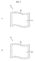
- FIG. 7 is a perspective view illustrating an example configuration of a second embodiment of a touch operation terminal to which the present technology is applied.
- FIG. 7A illustrates a front surface side of the touch operation terminal 51
- FIG. 7B illustrates a rear surface side of the touch operation terminal 51 .
- the touch operation terminal 51 is entirely made of a thin body 52 that is flexible and bendable, and is configured such that the display unit 53 is disposed at the front surface side of the body 52 and the input unit 54 is disposed at the rear surface side of the body 52 . That is, the display unit 53 and the input unit 54 are disposed to face opposite sides to each other.
- the input direction and the output direction are opposite to each other similarly to a state where the relative angle ⁇ is 360° as illustrated in FIG. 3D .
- the display unit 53 which is a flexible display, controls display of the display screen in the output direction, the orientation of which is switched with respect to the input direction according to the relative angle ⁇ similarly to the display unit 16 of FIG. 1 .
- the input unit 54 which is a flexible touch panel, acquires operation information indicating the input direction according to the swipe operation of the user, similarly to the input unit 15 of FIG. 1 .
- the touch operation terminal 51 includes the operation processing unit 21 ( FIG. 2 ) which is implemented by a flexible board and is embedded in the body 52 .
- the touch operation terminal 51 can be flexibly bent at an arbitrary position and therefore, a portion of the input unit 54 can be in a state of facing in a direction toward the display unit 53 (toward the front surface). That is, when the touch operation terminal 51 is bent, the relative angle between the display unit 53 and the input unit 54 is changed, and the relative angle is detectable by the relative angle detection unit 23 of the operation processing unit 21 . Therefore, when the relative angle detection unit 23 detects the relative angle at which the portion of the input unit 54 is in the state of facing the direction toward the display unit 53 , an image is displayed on the portion of the input unit 54 (in FIG. 8 , a portion facing the front of the paper) in the touch operation terminal 51 . Also, the portion of the input unit 54 can input a swipe operation by a user.
- the output direction with respect to the input direction is switched respectively upon the swipe operation on the portion of the input unit 54 facing the front surface side and the swipe operation on the portion of the input unit 54 facing the rear surface side. That is, the operation processing is performed on the portion of the input unit 54 which is determined as facing the front surface side according to the relative angle detected by the relative angle detection unit 23 such that the input direction is the same direction as the output direction.
- the portion of the input unit 54 faces the front surface side and an area of the rear portion of the touch operation terminal 51 , that is, an area of the input unit 54 facing the rear surface side becomes narrow.
- the above configuration is similarly applied to a case where the touch operation terminal 51 is in a state of being bent in the opposite direction of FIG. 8 , that is, a portion of the display unit 53 is in a state of facing a direction toward the input unit 54 (toward the rear surface side).
- the touch operation terminal 51 can change the user interface that is displayed when the display unit 53 and the input unit 54 are bent.
- the touch operation terminal 51 can display a menu screen 55 used to perform an operation with respect to the display screen that is being displayed on the display unit 53 on a portion of the input unit 54 facing in the front surface side by bending the display unit 53 and the input unit 54 .
- One or a plurality of graphical user interfaces (GUI) can be displayed on the menu screen 55 .
- the menu screen 55 is displayed when bending is detected. Additionally, the touch operation terminal 51 can detect a bendable position, change the size of the menu screen 55 according to the position, and change the number of GUIs to be displayed on the menu screen 55 . Accordingly, when the portion of the input unit 54 that is facing the front surface side become large by bending the touch operation terminal 51 , the menu screen 55 is largely displayed and many GUIs are displayed on the menu screen 55 .
- the touch operation terminal 51 may adjust an output amount (for example, scroll speed) with respect to an input amount in addition to switching of the output direction with respect to the input direction, according to an angle at which the display unit 53 and the input unit 54 are bent. Furthermore, the touch operation terminal 51 is not only bent to be folded into two portions as illustrated in FIGS. 8 and 9 , but is also capable of being folded to divided into three or four portions, and operation processing may be different according to respective folding methods.
- an output amount for example, scroll speed
- the touch operation terminal 51 may employ a semi-transparent member as the display unit 53 and the input unit 54 , so that the display unit 53 may be visible through the input unit 54 when the touch operation terminal 51 is bent.
- each process described referring to the flowchart above includes a process that is not necessarily performed in a time series manner in the order described in the flowchart, but may be performed in a parallel or individual manner (for example, a paralleled process or a process by objects).
- the program may be processed by one CPU, or processed by a plurality of CPUs in a distributed manner.
- the above-described series of processing may be performed by hardware or may be performed by software.
- a program forming the software is installed into a computer that is incorporated in a dedicated hardware, or installed from a program storage medium on which programs are recorded into a general-purpose computer or the like that can perform various types of functions by installing various types of programs.
- FIG. 10 is a block diagram showing an example configuration of the hardware of a computer that executes the series of processes described earlier according to a program.
- a CPU 102 In a computer 101 , a CPU 102 , a ROM 103 , a RAM 104 , and an EEPROM 105 are connected to one another through a bus 106 .
- An input/output interface 107 is connected to the bus 106 , and an external device, for example, the input unit 15 and the display unit 16 of FIG. 1 are connected to the input/output interface 107 .
- the CPU 102 loads a program stored in, for example, the ROM 103 or the EEPROM 105 into the RAM 104 through the bus 106 and executes the program, thereby performing the above-described series of processing.
- the program which is executed by the computer (CPU 102 ) can be provided through, for example, non-illustrated other recording mediums which are previously stored in the ROM 103 and the EEPROM 105 or various types of communication networks, and can be installed in the EEPROM 105 .
- present technology may also be configured as below.
- An operation processing device including:
- an input direction acquisition unit configured to acquire information indicating an input direction according to a direction generated in response to an operation indicating the direction which is performed on an input unit to which the operation is input;
- an output direction indication unit configured to indicate, to a display unit configured to display an image, an output direction that is a direction in which the image of the display unit is changed in response to the operation on the input unit;
- a determination unit configured to determine an orientation of the output direction with respect to the input direction according to a relative position relationship between the input unit and the display unit.
- the operation processing device further including:
- connection part configured to connect the input unit and the display unit to be openable and closeable
- the determination unit determines the orientation of the output direction with respect to the input direction according to a relative angle between the input unit and the display unit with the connection part as a center.
- connection part connects the input unit and the display unit so as to be openable and closeable in a range from an angle at which the input unit and the display unit face each other to an angle at which the input unit and the display unit face opposite sides to each other.
- an output amount in the output direction with respect to an input amount in the input direction is adjusted according to a relative position relationship between a user which performs input on the input unit and the display unit.
- the input unit and the display unit are configured to have flexibility to be flexibly bendable at an arbitrary position and are disposed to face opposite sides to each other.
Landscapes
- Engineering & Computer Science (AREA)
- Theoretical Computer Science (AREA)
- General Engineering & Computer Science (AREA)
- Computer Hardware Design (AREA)
- Physics & Mathematics (AREA)
- General Physics & Mathematics (AREA)
- Human Computer Interaction (AREA)
- Mathematical Physics (AREA)
- User Interface Of Digital Computer (AREA)
Applications Claiming Priority (3)
| Application Number | Priority Date | Filing Date | Title |
|---|---|---|---|
| JP2012154229 | 2012-07-10 | ||
| JP2012-154229 | 2012-07-10 | ||
| PCT/JP2013/068081 WO2014010458A1 (ja) | 2012-07-10 | 2013-07-02 | 操作処理装置および操作処理方法、並びにプログラム |
Related Parent Applications (1)
| Application Number | Title | Priority Date | Filing Date |
|---|---|---|---|
| PCT/JP2013/068081 A-371-Of-International WO2014010458A1 (ja) | 2012-07-10 | 2013-07-02 | 操作処理装置および操作処理方法、並びにプログラム |
Related Child Applications (1)
| Application Number | Title | Priority Date | Filing Date |
|---|---|---|---|
| US15/866,519 Continuation US10248234B2 (en) | 2012-07-10 | 2018-01-10 | Operation processing device and operation processing method for displaying image based on orientation of output direction |
Publications (2)
| Publication Number | Publication Date |
|---|---|
| US20150277600A1 US20150277600A1 (en) | 2015-10-01 |
| US9891729B2 true US9891729B2 (en) | 2018-02-13 |
Family
ID=49915921
Family Applications (4)
| Application Number | Title | Priority Date | Filing Date |
|---|---|---|---|
| US14/409,620 Active US9891729B2 (en) | 2012-07-10 | 2013-07-02 | Operation processing device and method for user interface |
| US15/866,519 Active US10248234B2 (en) | 2012-07-10 | 2018-01-10 | Operation processing device and operation processing method for displaying image based on orientation of output direction |
| US16/286,332 Active US10860121B2 (en) | 2012-07-10 | 2019-02-26 | Information processing appartus and method for controlling a display unit based on relative relationship between an input unit and the display unit |
| US17/093,819 Active US11487368B2 (en) | 2012-07-10 | 2020-11-10 | Operation processing device and operation processing method for controlling display unit based on change in output direction of display unit |
Family Applications After (3)
| Application Number | Title | Priority Date | Filing Date |
|---|---|---|---|
| US15/866,519 Active US10248234B2 (en) | 2012-07-10 | 2018-01-10 | Operation processing device and operation processing method for displaying image based on orientation of output direction |
| US16/286,332 Active US10860121B2 (en) | 2012-07-10 | 2019-02-26 | Information processing appartus and method for controlling a display unit based on relative relationship between an input unit and the display unit |
| US17/093,819 Active US11487368B2 (en) | 2012-07-10 | 2020-11-10 | Operation processing device and operation processing method for controlling display unit based on change in output direction of display unit |
Country Status (3)
| Country | Link |
|---|---|
| US (4) | US9891729B2 (ja) |
| JP (1) | JPWO2014010458A1 (ja) |
| WO (1) | WO2014010458A1 (ja) |
Cited By (2)
| Publication number | Priority date | Publication date | Assignee | Title |
|---|---|---|---|---|
| US10606379B2 (en) | 2014-05-06 | 2020-03-31 | Semiconductor Energy Laboratory Co., Ltd. | Electronic device |
| USRE48155E1 (en) * | 2013-02-01 | 2020-08-11 | Samsung Display Co., Ltd. | Mobile device including a flexible display device and method of operating the same |
Families Citing this family (7)
| Publication number | Priority date | Publication date | Assignee | Title |
|---|---|---|---|---|
| KR101569776B1 (ko) * | 2009-01-09 | 2015-11-19 | 삼성전자주식회사 | 접히는 표시부를 가지는 휴대 단말기 및 이의 운용 방법 |
| KR101889838B1 (ko) * | 2011-02-10 | 2018-08-20 | 삼성전자주식회사 | 터치 스크린 디스플레이를 구비한 휴대 기기 및 그 제어 방법 |
| WO2014010458A1 (ja) * | 2012-07-10 | 2014-01-16 | ソニー株式会社 | 操作処理装置および操作処理方法、並びにプログラム |
| KR102082781B1 (ko) * | 2013-04-01 | 2020-03-02 | 삼성디스플레이 주식회사 | 폴더블 디스플레이 장치 및 이의 제어 방법 및 장치. |
| JP2015141526A (ja) * | 2014-01-28 | 2015-08-03 | ソニー株式会社 | 情報処理装置、情報処理方法、及びプログラム |
| US10248224B2 (en) | 2016-10-25 | 2019-04-02 | Microsoft Technology Licensing, Llc | Input based on interactions with a physical hinge |
| JPWO2018150757A1 (ja) | 2017-02-17 | 2019-12-12 | ソニー株式会社 | 情報処理システム、情報処理方法、およびプログラム |
Citations (20)
| Publication number | Priority date | Publication date | Assignee | Title |
|---|---|---|---|---|
| US5268817A (en) * | 1990-04-27 | 1993-12-07 | Kabushiki Kaisha Toshiba | Portable computer with keyboard and having display with coordinate input tablet rotatably mounted to face either toward or away from keyboard when closed over keyboard |
| US5481430A (en) * | 1990-04-27 | 1996-01-02 | Kabushiki Kaisha Toshiba | Portable computer having keyboard and coordinate input tablet hingedly connected to a main body case through a groove |
| JPH08194667A (ja) | 1995-01-20 | 1996-07-30 | Matsushita Electric Ind Co Ltd | 情報処理装置 |
| US5719799A (en) * | 1994-07-07 | 1998-02-17 | Olympus Optical Co., Ltd. | Portable information processing apparatus |
| JP2002278515A (ja) | 2001-03-15 | 2002-09-27 | Minolta Co Ltd | 画像表示装置 |
| JP2003058316A (ja) | 2001-08-21 | 2003-02-28 | Sharp Corp | 携帯端末 |
| US20040001049A1 (en) * | 2002-06-27 | 2004-01-01 | Oakley Nicholas W. | Multiple mode display apparatus |
| US20040001306A1 (en) * | 2002-06-27 | 2004-01-01 | Oakley Nicholas W. | Transformable computing apparatus |
| JP2009031368A (ja) | 2007-07-24 | 2009-02-12 | Nec Corp | 画面表示制御方法、画面表示制御方式、電子機器及びプログラム |
| JP2010135967A (ja) | 2008-12-03 | 2010-06-17 | Casio Hitachi Mobile Communications Co Ltd | 携帯端末装置、及びプログラム |
| US20100245106A1 (en) * | 2009-03-30 | 2010-09-30 | Microsoft Corporation | Mobile Computer Device Binding Feedback |
| US20100245209A1 (en) * | 2009-03-27 | 2010-09-30 | Microsoft Corporation | Mobile computer device display postures |
| US20100321275A1 (en) * | 2009-06-18 | 2010-12-23 | Microsoft Corporation | Multiple display computing device with position-based operating modes |
| JP2012057662A (ja) | 2010-09-06 | 2012-03-22 | Sony Corp | 電子機器 |
| US20130229568A1 (en) * | 2012-03-02 | 2013-09-05 | Microsoft Corporation | Mobile Device Power State |
| US20140043259A1 (en) * | 2012-08-08 | 2014-02-13 | Samsung Electronics Co., Ltd. | Electronic apparatus and method of control thereof |
| US20140071608A1 (en) * | 2012-09-07 | 2014-03-13 | Panasonic Corporation | Electronic device |
| US20140152576A1 (en) * | 2012-10-10 | 2014-06-05 | Samsung Electronics Co., Ltd | Multi display apparatus, input pen, multi display apparatus controlling method, and multi display system |
| US20150116364A1 (en) * | 2013-10-29 | 2015-04-30 | Dell Products, Lp | System and Method for Display Power Management for Dual Screen Display Device |
| US20150116362A1 (en) * | 2013-10-29 | 2015-04-30 | Dell Products, Lp | System and Method for Positioning an Application Window Based on Usage Context for Dual Screen Display Device |
Family Cites Families (4)
| Publication number | Priority date | Publication date | Assignee | Title |
|---|---|---|---|---|
| JP3648476B2 (ja) * | 2001-11-30 | 2005-05-18 | 株式会社東芝 | 携帯情報機器 |
| JP4025712B2 (ja) * | 2003-11-04 | 2007-12-26 | Necパーソナルプロダクツ株式会社 | 情報処理装置、コンピュータ、情報処理装置の動作方法 |
| JP2011146915A (ja) * | 2010-01-14 | 2011-07-28 | Sony Corp | 情報処理装置、開閉角度検出方法及び開閉角度検出プログラム |
| WO2014010458A1 (ja) * | 2012-07-10 | 2014-01-16 | ソニー株式会社 | 操作処理装置および操作処理方法、並びにプログラム |
-
2013
- 2013-07-02 WO PCT/JP2013/068081 patent/WO2014010458A1/ja active Application Filing
- 2013-07-02 JP JP2014524747A patent/JPWO2014010458A1/ja active Pending
- 2013-07-02 US US14/409,620 patent/US9891729B2/en active Active
-
2018
- 2018-01-10 US US15/866,519 patent/US10248234B2/en active Active
-
2019
- 2019-02-26 US US16/286,332 patent/US10860121B2/en active Active
-
2020
- 2020-11-10 US US17/093,819 patent/US11487368B2/en active Active
Patent Citations (20)
| Publication number | Priority date | Publication date | Assignee | Title |
|---|---|---|---|---|
| US5481430A (en) * | 1990-04-27 | 1996-01-02 | Kabushiki Kaisha Toshiba | Portable computer having keyboard and coordinate input tablet hingedly connected to a main body case through a groove |
| US5268817A (en) * | 1990-04-27 | 1993-12-07 | Kabushiki Kaisha Toshiba | Portable computer with keyboard and having display with coordinate input tablet rotatably mounted to face either toward or away from keyboard when closed over keyboard |
| US5719799A (en) * | 1994-07-07 | 1998-02-17 | Olympus Optical Co., Ltd. | Portable information processing apparatus |
| JPH08194667A (ja) | 1995-01-20 | 1996-07-30 | Matsushita Electric Ind Co Ltd | 情報処理装置 |
| JP2002278515A (ja) | 2001-03-15 | 2002-09-27 | Minolta Co Ltd | 画像表示装置 |
| JP2003058316A (ja) | 2001-08-21 | 2003-02-28 | Sharp Corp | 携帯端末 |
| US20040001049A1 (en) * | 2002-06-27 | 2004-01-01 | Oakley Nicholas W. | Multiple mode display apparatus |
| US20040001306A1 (en) * | 2002-06-27 | 2004-01-01 | Oakley Nicholas W. | Transformable computing apparatus |
| JP2009031368A (ja) | 2007-07-24 | 2009-02-12 | Nec Corp | 画面表示制御方法、画面表示制御方式、電子機器及びプログラム |
| JP2010135967A (ja) | 2008-12-03 | 2010-06-17 | Casio Hitachi Mobile Communications Co Ltd | 携帯端末装置、及びプログラム |
| US20100245209A1 (en) * | 2009-03-27 | 2010-09-30 | Microsoft Corporation | Mobile computer device display postures |
| US20100245106A1 (en) * | 2009-03-30 | 2010-09-30 | Microsoft Corporation | Mobile Computer Device Binding Feedback |
| US20100321275A1 (en) * | 2009-06-18 | 2010-12-23 | Microsoft Corporation | Multiple display computing device with position-based operating modes |
| JP2012057662A (ja) | 2010-09-06 | 2012-03-22 | Sony Corp | 電子機器 |
| US20130229568A1 (en) * | 2012-03-02 | 2013-09-05 | Microsoft Corporation | Mobile Device Power State |
| US20140043259A1 (en) * | 2012-08-08 | 2014-02-13 | Samsung Electronics Co., Ltd. | Electronic apparatus and method of control thereof |
| US20140071608A1 (en) * | 2012-09-07 | 2014-03-13 | Panasonic Corporation | Electronic device |
| US20140152576A1 (en) * | 2012-10-10 | 2014-06-05 | Samsung Electronics Co., Ltd | Multi display apparatus, input pen, multi display apparatus controlling method, and multi display system |
| US20150116364A1 (en) * | 2013-10-29 | 2015-04-30 | Dell Products, Lp | System and Method for Display Power Management for Dual Screen Display Device |
| US20150116362A1 (en) * | 2013-10-29 | 2015-04-30 | Dell Products, Lp | System and Method for Positioning an Application Window Based on Usage Context for Dual Screen Display Device |
Cited By (5)
| Publication number | Priority date | Publication date | Assignee | Title |
|---|---|---|---|---|
| USRE48155E1 (en) * | 2013-02-01 | 2020-08-11 | Samsung Display Co., Ltd. | Mobile device including a flexible display device and method of operating the same |
| USRE49755E1 (en) | 2013-02-01 | 2023-12-12 | Samsung Display Co., Ltd. | Mobile device including a flexible display device and method of operating the same |
| US10606379B2 (en) | 2014-05-06 | 2020-03-31 | Semiconductor Energy Laboratory Co., Ltd. | Electronic device |
| US11216106B2 (en) | 2014-05-06 | 2022-01-04 | Semiconductor Energy Laboratory Co., Ltd. | Electronic device |
| US11740728B2 (en) | 2014-05-06 | 2023-08-29 | Semiconductor Energy Laboratory Co., Ltd. | Electronic device |
Also Published As
| Publication number | Publication date |
|---|---|
| US20210055812A1 (en) | 2021-02-25 |
| US20190196616A1 (en) | 2019-06-27 |
| US20150277600A1 (en) | 2015-10-01 |
| US20180129318A1 (en) | 2018-05-10 |
| US10248234B2 (en) | 2019-04-02 |
| WO2014010458A1 (ja) | 2014-01-16 |
| US10860121B2 (en) | 2020-12-08 |
| JPWO2014010458A1 (ja) | 2016-06-23 |
| US11487368B2 (en) | 2022-11-01 |
Similar Documents
| Publication | Publication Date | Title |
|---|---|---|
| US11487368B2 (en) | Operation processing device and operation processing method for controlling display unit based on change in output direction of display unit | |
| US9128665B2 (en) | Information processing device and program | |
| US9798395B2 (en) | Electronic control apparatus and method for responsively controlling media content displayed on portable electronic device | |
| CN103988159B (zh) | 显示控制装置和显示控制方法 | |
| US20180088775A1 (en) | Method of controlling mobile device with touch-sensitive display and motion sensor, and mobile device | |
| US20170293383A1 (en) | Portable device and method for controlling same | |
| JP2019516187A (ja) | 誤操作を防止するディスプレイインタフェース制御方法、装置及び端末 | |
| US20150091824A1 (en) | Information processing apparatus, information processing method, and computer program | |
| US20130135178A1 (en) | Information processing terminal and control method thereof | |
| EP2752753A2 (en) | Terminal and method for operating the same | |
| US20150002433A1 (en) | Method and apparatus for performing a zooming action | |
| US20170345397A1 (en) | Information processing device and image display method | |
| WO2014120177A1 (en) | Touch screen with unintended input prevention | |
| US20170168594A1 (en) | Electronic apparatus and method | |
| US20140195935A1 (en) | Information processing device, information processing method, and information processing program | |
| US9823890B1 (en) | Modifiable bezel for media device | |
| JP2018072986A (ja) | 情報処理装置、画像表示方法、及び画像表示プログラム | |
| JP6153487B2 (ja) | 端末及び制御方法 | |
| EP2815295B1 (en) | Display and method in an electric device | |
| JP5861359B2 (ja) | 携帯機器、ページ切り換え方法及びページ切り換えプログラム | |
| WO2016001730A1 (en) | Operation device and operation method | |
| US20070262957A1 (en) | Menu selection method and apparatus using pointing device | |
| JP2019096182A (ja) | 電子装置、表示方法、およびプログラム | |
| JP2013105084A (ja) | 情報表示システム | |
| JP2014215890A (ja) | 電子機器、情報処理方法及び情報処理プログラム |
Legal Events
| Date | Code | Title | Description |
|---|---|---|---|
| AS | Assignment |
Owner name: SONY CORPORATION, JAPAN Free format text: ASSIGNMENT OF ASSIGNORS INTEREST;ASSIGNORS:MIZUNUMA, HIROYUKI;NODA, TAKURO;YAMANO, IKUO;SIGNING DATES FROM 20141106 TO 20141107;REEL/FRAME:034702/0851 |
|
| STCF | Information on status: patent grant |
Free format text: PATENTED CASE |
|
| MAFP | Maintenance fee payment |
Free format text: PAYMENT OF MAINTENANCE FEE, 4TH YEAR, LARGE ENTITY (ORIGINAL EVENT CODE: M1551); ENTITY STATUS OF PATENT OWNER: LARGE ENTITY Year of fee payment: 4 |