US989082A - Fence-gate. - Google Patents
Fence-gate. Download PDFInfo
- Publication number
- US989082A US989082A US55093210A US1910550932A US989082A US 989082 A US989082 A US 989082A US 55093210 A US55093210 A US 55093210A US 1910550932 A US1910550932 A US 1910550932A US 989082 A US989082 A US 989082A
- Authority
- US
- United States
- Prior art keywords
- gate
- arm
- fence
- locking
- locking member
- Prior art date
- Legal status (The legal status is an assumption and is not a legal conclusion. Google has not performed a legal analysis and makes no representation as to the accuracy of the status listed.)
- Expired - Lifetime
Links
Images
Classifications
-
- E—FIXED CONSTRUCTIONS
- E06—DOORS, WINDOWS, SHUTTERS, OR ROLLER BLINDS IN GENERAL; LADDERS
- E06B—FIXED OR MOVABLE CLOSURES FOR OPENINGS IN BUILDINGS, VEHICLES, FENCES OR LIKE ENCLOSURES IN GENERAL, e.g. DOORS, WINDOWS, BLINDS, GATES
- E06B9/00—Screening or protective devices for wall or similar openings, with or without operating or securing mechanisms; Closures of similar construction
- E06B9/52—Devices affording protection against insects, e.g. fly screens; Mesh windows for other purposes
- E06B9/521—Frameless fly screens; Tensioning means therefor
Definitions
- This invention relates to certain improvements in fence gates and refers more particularly to that class of gates made from wire, woven-wire or other materials that have to be brought to a tension to be effective.
- the main object is to provide a simple means whereby the gate may be locked and released in and from its operative position and the wires of the gate tightened or relaxed as the gate is locked or unlocked.
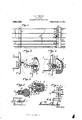
- Figure 1 is an elevation of my improved gate shown as constituting a part of a wire fence.
- Fig. 2 is an enlarged detailed sectional view partly in elevation of the locking and tightening device shown in its released position for relaxing the wires of the gate.
- Fig. 3 is a similar sectional view partly in elevation of the same mechanism shown in its locked position.
- Figs. 4: and 5 are horizontal sectional views taken respectively on lines 4-4, Fig. 3 and 5-5, Fig. 1.
- Fig. 6 is a top plan of the rotary locking member showing its bearings partly in section.
- the gate proper which forms the subject matter of the present invention is supported between suitable supports as gate posts -1- and --2 spaced a desired distance apart according to the use for which it is intended.
- This gate comprises a series of substantially horizontal flexible members as wires --8 located one above the other which are properly fastened to one of the supports, as 1, and extended across and to the opposite side of the gate opening where they are suitably fastened or anchored to an upright gate-stile or bar 5-.
- the wires 3- are more or less flexible or bendable and therefore constitute a flexible connection between the gate and post or support 1-- to permit the gate as an entirety including the bar -5, to be swung laterally to its full open or closed position or to any angle.
- This locking mechanism preferably comprises two locklng members 6 and 7- one of which as the locking member 6 consists of a laterally projecting arm having a hub 8 adjustably secured to the upright stile 5- by bolts -9-, which in this instance are passed through apertured ears -10- on opposite sides of the hub -8-.
- the looking member or arm --6 projects from the stile 5 toward the 0st 2-- and terminates in a suitable hinge pin or bearing 11, the intermediate portion of the arm 6 just back of the bearing pin -11 being slotted at 12- for the reception of the free end of the locking member -7-.
- This locking member 7- also consists of a laterally projecting arm having opposite journals 13- projecting laterally from opposite sides ofone end thereof, the opposite or free end of the arm -7 terminating in a hook or hearing -14 which is open preferably at the top when in position, shown in Fig. 2.
- the journals 13 of the arm -7- are seated in suitable bearings 15 formed on the ends of screws 16 which are screwed into the adjacent side of the post -2, so as to support the arm 7- in proper position relative to locking member 6-.
- the outer ends of the journals 13 are provided with parallel sockets or ferrules 17 for receiving suitable handles --18- whereby the locking member 7- may be rocked in the bearings 15- through. part of the arc of a circle, as shown in Figs. 2 and 3.
- the locking member -7- is rocked to the position shown in Fig. 2, so as to project laterally away from the post -2- with the open side of its hook-shaped bearing -14- at the top, so that the adjacent end of the gate may be lifted to disengage or unset the hinge pin -11 from the bearing -14L and thereby permit the gate to be swung laterally in either direction to its open or partly open position, as may be desired.
Landscapes
- Engineering & Computer Science (AREA)
- Structural Engineering (AREA)
- Life Sciences & Earth Sciences (AREA)
- Insects & Arthropods (AREA)
- Pest Control & Pesticides (AREA)
- Architecture (AREA)
- Civil Engineering (AREA)
- Gates (AREA)
Description
G. E. TOWNLBY.
FENCE GATE.
- APPLICATION mam mm. 22, 1910.
' 989,082. Patented A r.11,1'911.
l Inventor Jmoraey;
CHARLES E. TOWNLEY, 0F DRYDEN, NEW YORK.
FENCE-GATE.
Specification of Letters Patent.
Application filed March 22, 1910.
Patented Apr. 11, 1911.
Serial No. 550,932.
To all whom "it may concern:
Be it known that I, CHARLES E. TOWNLEY, of Dryden, in the county of Tompkins, in the State of New York, have invented new and useful Improvements in Fence-Gates, of which the following, taken in connection with the accompanying drawings, is a full, clear, and exact description.
This invention relates to certain improvements in fence gates and refers more particularly to that class of gates made from wire, woven-wire or other materials that have to be brought to a tension to be effective.
The main object is to provide a simple means whereby the gate may be locked and released in and from its operative position and the wires of the gate tightened or relaxed as the gate is locked or unlocked.
Other objects and uses relating more particularly to the tightening and locking devices will be brought out in the following description.
In the drawings: Figure 1 is an elevation of my improved gate shown as constituting a part of a wire fence. Fig. 2 is an enlarged detailed sectional view partly in elevation of the locking and tightening device shown in its released position for relaxing the wires of the gate. Fig. 3 is a similar sectional view partly in elevation of the same mechanism shown in its locked position. Figs. 4: and 5 are horizontal sectional views taken respectively on lines 4-4, Fig. 3 and 5-5, Fig. 1. Fig. 6 is a top plan of the rotary locking member showing its bearings partly in section.
The gate proper which forms the subject matter of the present invention is supported between suitable supports as gate posts -1- and --2 spaced a desired distance apart according to the use for which it is intended. This gate comprises a series of substantially horizontal flexible members as wires --8 located one above the other which are properly fastened to one of the supports, as 1, and extended across and to the opposite side of the gate opening where they are suitably fastened or anchored to an upright gate-stile or bar 5-. The wires 3- are more or less flexible or bendable and therefore constitute a flexible connection between the gate and post or support 1-- to permit the gate as an entirety including the bar -5, to be swung laterally to its full open or closed position or to any angle.
When the gate is closed as shown in Fig. 1, the stile or upright bar 5- is in close proximity and substantially parallel with the adjacent gate post --2-- where it is held in position by a suitable locking mechanism presently described. This locking mechanism preferably comprises two locklng members 6 and 7- one of which as the locking member 6 consists of a laterally projecting arm having a hub 8 adjustably secured to the upright stile 5- by bolts -9-, which in this instance are passed through apertured ears -10- on opposite sides of the hub -8-. The looking member or arm --6 projects from the stile 5 toward the 0st 2-- and terminates in a suitable hinge pin or bearing 11, the intermediate portion of the arm 6 just back of the bearing pin -11 being slotted at 12- for the reception of the free end of the locking member -7-. This locking member 7- also consists of a laterally projecting arm having opposite journals 13- projecting laterally from opposite sides ofone end thereof, the opposite or free end of the arm -7 terminating in a hook or hearing -14 which is open preferably at the top when in position, shown in Fig. 2.
The journals 13 of the arm -7- are seated in suitable bearings 15 formed on the ends of screws 16 which are screwed into the adjacent side of the post -2, so as to support the arm 7- in proper position relative to locking member 6-. The outer ends of the journals 13 are provided with parallel sockets or ferrules 17 for receiving suitable handles --18- whereby the locking member 7- may be rocked in the bearings 15- through. part of the arc of a circle, as shown in Figs. 2 and 3.
In opening the gate, the locking member -7- is rocked to the position shown in Fig. 2, so as to project laterally away from the post -2- with the open side of its hook-shaped bearing -14- at the top, so that the adjacent end of the gate may be lifted to disengage or unset the hinge pin -11 from the bearing -14L and thereby permit the gate to be swung laterally in either direction to its open or partly open position, as may be desired.
In locking the gate, the free end thereof is lifted into position to engage the pin -1l-- in the seat or hearing -14 in the shown in F ig. 3 by means of either of the handles 18, thereby drawing the stile 5 toward the post 2- and simultaneously straining or tightening the wires 3, the slot -12 permitting the pin ll? and hook to be carried to a plane slightly below the horizontal plane of the swinging axis of the arm 7 so as to aut ma cally ho he ga e n its locked posit-ion. It will be observed that the pull or strain npon the wires when tightened is in horizontal lines and when the locking members are in their locked position, as shown .i g- 3., w th t e l cking pin l and hook in a plane below the horizontal plane of the swinging axis of the arm ,7 the arm 6 is forced against the upper side of the base of the arm and prevents further downward movement of the locking members, thereby holding the gat in a substantially horizontal osition While the handles a sume an pr gh upward y projec ing p sit on- In re eas ng the gatefii'lolil itlooked position the handles .8 which may be operated from either the inside or outside of the fence are rocked downwardly in the direction indicated by the dotted lines, Fig. 3, thereby rocking the locking member 7 until the locking members and stile are brought to the position shown in Fig. 2, thereby permitting the gate to be released in the manner previously d sc ibed.
bers secured at one end to the support 1 and extending across the gate opening, i verticallypo ed bar connecting the opposite ends of the flexible gate members together, a downwardly cu ved lo king member for its inner end secured to the bar and projecting toward the support 2 and haying its .Outer end p ovided wi an eye, bearings ecured t the supp r 2 and a ranged in plane below the inner end of said locking member, a locking arm having its inner end provided with journals mounted in said bearings and its outer end formed with a hook engaging with said .eye, and a handle connected to each of said journals for rocking the locking ,arm in one direction thereby swinging the locking member .over the looking arm and closing the gate.
In witness whereof I'have hereunto set my hand on this 17th day of March, 1910.
CHARLES Witnesses:
JAMES B. FULKEnsoN, Gno. E. GOODRICH.
Copies of this patent may be obtained for five cents each, by addressing the Gomm issioner of iatents,
' Washington, D. G.
Priority Applications (1)
| Application Number | Priority Date | Filing Date | Title |
|---|---|---|---|
| US55093210A US989082A (en) | 1910-03-22 | 1910-03-22 | Fence-gate. |
Applications Claiming Priority (1)
| Application Number | Priority Date | Filing Date | Title |
|---|---|---|---|
| US55093210A US989082A (en) | 1910-03-22 | 1910-03-22 | Fence-gate. |
Publications (1)
| Publication Number | Publication Date |
|---|---|
| US989082A true US989082A (en) | 1911-04-11 |
Family
ID=3057420
Family Applications (1)
| Application Number | Title | Priority Date | Filing Date |
|---|---|---|---|
| US55093210A Expired - Lifetime US989082A (en) | 1910-03-22 | 1910-03-22 | Fence-gate. |
Country Status (1)
| Country | Link |
|---|---|
| US (1) | US989082A (en) |
-
1910
- 1910-03-22 US US55093210A patent/US989082A/en not_active Expired - Lifetime
Similar Documents
| Publication | Publication Date | Title |
|---|---|---|
| EP1136312A3 (en) | Hinge fitting for a vehicle seat | |
| DE4040291C2 (en) | Washing machine with a door | |
| US989082A (en) | Fence-gate. | |
| US165619A (en) | Improvement in hiwges | |
| US1224036A (en) | Hinge. | |
| US1123913A (en) | Gate-hinge. | |
| US587896A (en) | James h | |
| US1141828A (en) | Gate-hinge. | |
| US855961A (en) | Door-fastener. | |
| US1136989A (en) | Emergency-exit-door fastener. | |
| US875269A (en) | Table. | |
| US1033600A (en) | Gate-retainer. | |
| US414721A (en) | Elevator-case | |
| US1098591A (en) | Gate-hinge. | |
| US1033057A (en) | Adjusting mechanism for door-bolts. | |
| US414905A (en) | Trunk-hinge | |
| US1130874A (en) | Gate. | |
| US1198153A (en) | Door-holder. | |
| US369740A (en) | Triplicate mirror | |
| US536881A (en) | Gate-spring | |
| US1127385A (en) | Railway-gate. | |
| US883960A (en) | Gate-hinge. | |
| US1144899A (en) | Gate-closing device. | |
| US1086157A (en) | Cattle-stanchion. | |
| US949490A (en) | Hinge. |