US9847704B2 - Rotor assembly and method of manufacture for electric machines having multiple magnet lengths - Google Patents
Rotor assembly and method of manufacture for electric machines having multiple magnet lengths Download PDFInfo
- Publication number
- US9847704B2 US9847704B2 US14/932,590 US201514932590A US9847704B2 US 9847704 B2 US9847704 B2 US 9847704B2 US 201514932590 A US201514932590 A US 201514932590A US 9847704 B2 US9847704 B2 US 9847704B2
- Authority
- US
- United States
- Prior art keywords
- tab
- lamination sheets
- recess
- tabs
- lamination
- Prior art date
- Legal status (The legal status is an assumption and is not a legal conclusion. Google has not performed a legal analysis and makes no representation as to the accuracy of the status listed.)
- Active, expires
Links
Images


Classifications
-
- H—ELECTRICITY
- H02—GENERATION; CONVERSION OR DISTRIBUTION OF ELECTRIC POWER
- H02K—DYNAMO-ELECTRIC MACHINES
- H02K15/00—Methods or apparatus specially adapted for manufacturing, assembling, maintaining or repairing of dynamo-electric machines
- H02K15/02—Methods or apparatus specially adapted for manufacturing, assembling, maintaining or repairing of dynamo-electric machines of stator or rotor bodies
- H02K15/03—Methods or apparatus specially adapted for manufacturing, assembling, maintaining or repairing of dynamo-electric machines of stator or rotor bodies having permanent magnets
-
- H—ELECTRICITY
- H02—GENERATION; CONVERSION OR DISTRIBUTION OF ELECTRIC POWER
- H02K—DYNAMO-ELECTRIC MACHINES
- H02K1/00—Details of the magnetic circuit
- H02K1/06—Details of the magnetic circuit characterised by the shape, form or construction
- H02K1/22—Rotating parts of the magnetic circuit
- H02K1/27—Rotor cores with permanent magnets
- H02K1/2706—Inner rotors
- H02K1/272—Inner rotors the magnetisation axis of the magnets being perpendicular to the rotor axis
- H02K1/274—Inner rotors the magnetisation axis of the magnets being perpendicular to the rotor axis the rotor consisting of two or more circumferentially positioned magnets
- H02K1/2753—Inner rotors the magnetisation axis of the magnets being perpendicular to the rotor axis the rotor consisting of two or more circumferentially positioned magnets the rotor consisting of magnets or groups of magnets arranged with alternating polarity
- H02K1/276—Magnets embedded in the magnetic core, e.g. interior permanent magnets [IPM]
- H02K1/2766—Magnets embedded in the magnetic core, e.g. interior permanent magnets [IPM] having a flux concentration effect
-
- H—ELECTRICITY
- H02—GENERATION; CONVERSION OR DISTRIBUTION OF ELECTRIC POWER
- H02K—DYNAMO-ELECTRIC MACHINES
- H02K1/00—Details of the magnetic circuit
- H02K1/06—Details of the magnetic circuit characterised by the shape, form or construction
- H02K1/22—Rotating parts of the magnetic circuit
- H02K1/24—Rotor cores with salient poles ; Variable reluctance rotors
- H02K1/246—Variable reluctance rotors
Definitions
- This disclosure generally relates to internal permanent magnet electric machines and, more particularly, to a rotor assembly for the internal permanent magnet machine.
- An electric motor uses electric potential energy to produce mechanical energy through the interaction of magnetic fields and current-carrying conductors.
- the reverse process, using mechanical energy to produce electrical energy, is accomplished by a generator or dynamo.
- Other electric machines, such as motor/generators, combine various features of both motors and generators.
- Electric machines may include an element rotatable about a central axis.
- the rotatable element which may be referred to as a rotor, may be coaxial with a static element, which may be referred to as a stator.
- the electric machine uses relative rotation between the rotor and stator to produce mechanical energy or electrical energy.
- An improved method, structure, or system for creating internal permanent magnet rotors is provided.
- the system selectively creates rotor assemblies for at least two different magnet lengths by selectively creating tab retention and recess features in lamination sheets of the rotors.
- the rotor assembly may be created by selectively creating first and second tabs extending into apertures of lamination sheets.
- the first and second tabs may be selectively removed, depending on the different magnet lengths and the specific lamination sheet, according to one of a first finishing schedule and a second finishing schedule.
- the lamination sheets are stacked with any remaining first and second tabs, and other features, aligned.
- FIG. 1 is a schematic, diagrammatic view of an electric machine.
- FIG. 2 is a schematic, partially exploded, fragmentary cross sectional view of a rotor assembly of an electric machine, such as that shown and described in FIG. 1 .
- FIG. 3 is a schematic plan view of a laminated sheet for a rotor assembly, such as those usable with the electric machine shown and described in FIG. 1 and FIG. 2 .
- FIG. 4A is a schematic plan view of a portion of a laminated sheet for a rotor assembly configured for multiple magnet lengths, and illustrated a short magnet.
- FIG. 4B is a schematic plan view of a laminated sheet related to that shown in FIG. 4A , configured with a long magnet.
- FIG. 5 is a schematic, partially-exploded, fragmentary cross sectional view of the rotor assembly configured for multiple magnet lengths.
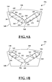
- FIG. 6A is a schematic plan view of a portion of a laminated sheet for a rotor assembly configured for multiple magnet lengths, configured with a long magnet.
- FIG. 6B is a schematic plan view of a laminated sheet related to that shown in FIG. 6A , configured with a very short magnet.
- FIG. 1 an electric machine 20 , which may be referred to as an interior permanent magnet electric machine 20 .
- the electric machine 20 includes a housing 22 supporting a stator assembly 24 .
- a rotor assembly 26 is rotatably attached to the housing 22 for rotation about a longitudinal or central axis 28 relative to the housing 22 and the stator assembly 24 .
- a shaft 30 is attached to the rotor assembly 26 for rotation with the rotor assembly 26 about the central axis 28 .
- the rotor assembly 26 is disposed within a central opening 32 of the stator assembly 24 , and is concentric with the stator assembly 24 about the central axis 28 .
- FIG. 1 depicts a typical electric machine 20
- the electric machine 20 may be configured in some other manner, such as for example with the rotor assembly 26 disposed annularly outside an outer periphery of the stator assembly 24 . Accordingly, the scope of the claims is not limited to the specific configuration of the electric machine 20 shown and described herein.
- the rotor assembly 26 includes a plurality of lamination sheets 34 .
- Each of the lamination sheets 34 is preferably manufactured from steel, such as but not limited to non-orientated electrical steel.
- the lamination sheets 34 are disposed adjacent each other along the central axis 28 to define a laminated stack 36 , shown in FIG. 2 .
- the laminated stack 36 forms a core of the rotor assembly 26 .
- the lamination sheets 34 are concentrically aligned along the central axis 28 to form the laminated stack 36 .
- each of the lamination sheets 34 defines at least one, and preferably a plurality of apertures 38 .
- a aperture punch may be used to form the apertures 38 .
- the plurality of apertures 38 in the lamination sheets 34 is aligned with each other to define a plurality of slots 40 .
- the slots 40 extend parallel with the central axis 28 .
- the slots 40 are generally referred to by reference numeral 40 .
- a first slot is specifically referred to by reference numeral 40 A
- a second slot is specifically referred to as 40 B
- a third slot is specifically referred to as 40 C.
- the rotor assembly 26 includes a plurality of magnets 42 .
- One of the plurality of magnets 42 is disposed within each of the plurality of slots 40 .
- the magnets 42 are generally referred to by reference numeral 42 .
- a first magnet 42 is specifically referred to by reference numeral 42 A, and a second magnet 42 is specifically referred to as 42 B.
- the magnet 42 of each slot 40 is sized and shaped to fit within its respective slot 40 . Accordingly, if the slot 40 includes a curved cross sectional shape perpendicular to the central axis 28 , then the magnet 42 includes a corresponding curved cross sectional shape perpendicular to the central axis 28 so as to fit within the slot 40 .
- the slots 40 and their respective magnets 42 may be formed to include curved cross sectional shapes or rectangular cross sectional shapes relative to the central axis 28 .
- the magnets 42 may include, but are not limited to, ferrite magnets 42 or rare earth magnets 42 , such as NdFeB.
- the plurality of lamination sheets 34 includes at least one group of standard lamination sheets 44 , at least one group of recess lamination sheets 46 , and at least one tab lamination sheet 48 .
- the group of standard lamination sheets 44 include a plurality of standard lamination sheets 44 grouped or stacked together, such as by a stacking mechanism, with each of the lamination sheets 34 disposed within the group of standard lamination sheets 44 being substantially identical.
- the group of recess lamination sheets 46 includes a plurality of recess lamination sheets 46 grouped or stacked together, with each of the lamination sheets 34 disposed within the group of recess lamination sheets 46 being substantially identical.
- the tab lamination sheet 48 is disposed between the group of standard lamination sheets 44 and the group of recess lamination sheets 46 .
- the rotor assembly 26 may include multiple groups of standard lamination sheets 44 , multiple groups of recess lamination sheets 46 , with multiple tab lamination sheets 48 , arranged in an alternating relationship. As such, an individual tab lamination sheet 48 is disposed between one group of standard lamination sheets 44 and one group of recess lamination sheets 46 . Furthermore, the combination of one tab lamination sheet 48 and one group of recess lamination sheets 46 may be referred to as a laminated retention system.
- the rotor assembly 26 may include multiple laminated retention systems throughout the laminated stack 36 , with each laminated retention system separated by one group of standard lamination sheets 44 .
- the laminated retention system includes one tab lamination sheet 48 and one group of recess lamination sheets 46 .
- the tab laminated sheet 48 includes a plurality of tabs 50 . At least one of the plurality of tabs 50 extends into each of the plurality of apertures 38 of the respective tab lamination sheet 48 , and thereby into each of the plurality of slots 40 of the rotor assembly 26 . Each tab 50 extends into abutting engagement with the magnet 42 disposed within the respective slot 40 of the tab 50 .
- the tab lamination sheet 48 is initially formed such that the tab 50 is coplanar with the tab lamination sheet 48 , and extends radially outward from the central axis 28 once installed in the laminated stack 36 .
- the initial position of a tab 50 is shown in FIG. 2 in the first slot 40 A.
- the magnets 42 of the respective slots 40 are axially inserted parallel with the central axis 28 into their respective slots 40 , from an axial end, i.e., an insertion end, of laminated stack 36 .
- the direction of insertion of the magnets 42 is generally indicated by the direction arrow 52 .
- the magnets 42 contact the tabs 50 within their respective slots 40 , and bend the tabs 50 out of their way. In so doing, the tabs 50 are bent to an approximately parallel relationship relative to the slots 40 and the central axis 28 .
- the final, bent position of a tab 50 is shown in FIG. 2 in the second slot 40 B.
- the tab 50 thereof includes a radial length 54 measured radially relative to the central axis 28 .
- the tab 50 of the first slot 40 A prior to insertion of the first magnet 42 A, extends into the first slot 40 A a distance that is equal to the radial length 54 .
- the radial length 54 of the tabs 50 is between the range of 1 mm and 3 mm.
- the radial length 54 of the tabs 50 may vary from the exemplary embodiment.
- the radial length 54 of the tabs 50 may vary based on the specific size, shape and configuration of the slots 40 and their respective magnets 42 .
- the tabs 50 act as a spring to bias their respective magnets 42 against an opposing wall 56 of their respective slots 40 .
- the tabs 50 bias the magnets 42 against the wall 56 to secure the respective magnet 42 in position relative to the laminated stack 36 .
- the tabs 50 bias their respective magnets 42 toward a radially outer wall 56 of the slot 40 relative to the central axis 28 .
- the tabs 50 may be positioned relative to the slot 40 to bias the magnets 42 toward some other radially positioned wall 56 of the slot 40 . Because the tabs 50 bias the magnets 42 against the wall 56 of the laminated stack 36 to secure the position of the magnets 42 relative to the laminated stack 36 , the rotor assembly 26 does not require any adhesive for bonding the magnets 42 to the laminated stack.
- each of the plurality of apertures 38 of each of the recess lamination sheets 46 includes a groove portion 58 .
- each of the recess lamination sheets 46 are stacked adjacent to each other such that the groove portions 58 of each respective recess lamination sheet 46 are disposed adjacent each other to define a plurality of grooves 60 extending parallel with the central axis 28 .
- One of the plurality of grooves 60 is disposed within each of the plurality of slots 40 , adjacent and directly behind the respective tab 50 of the slot 40 , relative to the direction of insertion of the magnets 42 .
- each tab 50 of the tab lamination sheet 48 is at least partially disposed within the respective groove 60 of the slot 40 defined by the recess lamination sheets 46 .
- Each groove 60 defines a longitudinal length 62 measured parallel with the central axis 28 .
- the longitudinal length 62 of the groove 60 is greater than the radial length 54 of the tab 50 , so that when each tab 50 is bent into its final position, the tab 50 does not bind between the slot 40 and the magnet 42 and prevent insertion of the magnet 42 into its respective slot 40 .
- the grooves 60 are recessed into the laminated stack 36 from their respective slots 40 at least a recess distance 64 .
- the lamination sheets 34 and the tabs 50 include a thickness measured parallel with the central axis 28 .
- the recess distance 64 is preferably equal to or greater than a thickness of the lamination sheets 34 .
- the lamination sheets 34 and the tabs 50 include a thickness measured parallel with the central axis 28 that is between the range of 0.25 mm and 0.5 mm.
- the recess distance 64 that the grooves 60 are recessed from the slots 40 is equal to or greater than 0.25 mm.
- the thickness of the lamination sheets 34 and the tabs 50 , and the recess distance 64 of the grooves 60 may vary.
- the rotor assembly 126 shares many features with the rotor assembly 26 , and description of shared features and functions may be omitted from the description of the rotor assembly 126 .
- FIG. 4A shows a plan view of a portion of the rotor assembly 126 , illustrating configuration for short magnets.
- FIG. 4B shows a plan view of a portion of the rotor assembly 126 , illustrating configuration for long magnets.
- FIG. 5 shows a partially-exploded, isometric view similar to the portion of the rotor assembly 126 shown in FIG. 4A .
- the rotor assembly 126 includes a plurality of lamination sheets 134 .
- Each of the lamination sheets 134 may be manufactured from steel, such as but not limited to non-orientated electrical steel.
- the lamination sheets 134 are disposed adjacent each other along a central axis (not shown) to define a laminated stack 136 , as shown in FIG. 5 .
- the laminated stack 136 forms a core of the rotor assembly 126 .
- the lamination sheets 134 are concentrically aligned along the central axis to form the laminated stack 136 .
- the lamination sheets 134 define at least one aperture (not separately numbered), and preferably a plurality of apertures, which may be created or formed by an aperture punch.
- the apertures in the lamination sheets 134 are aligned with each other to define one or more slots 140 , which extend parallel with the central axis. Only one of the slots 140 is illustrated in FIG. 5 .
- the rotor assembly 126 includes a plurality of magnets, one or more of which is disposed within each of the slots 140 .
- the magnet of each slot 140 is sized and shaped to fit within the respective slot 140 .
- the rotor assembly 126 may be configured to receive magnets of different length, as described herein.
- FIG. 4A and FIG. 5 illustrate the rotor assembly 126 configured with a short magnet 142 .
- FIG. 4B illustrates the rotor assembly 126 configured with a long magnet 143 .
- Each of the configurations of the rotor assembly 126 shown in FIGS. 4A, 4B, and 5 is formed in a common stamping tool.
- the lamination sheets 134 include at least one group of standard lamination sheets 144 , at least one group of recess lamination sheets 146 , and at least one tab lamination sheet 148 .
- the group of standard lamination sheets 144 includes a plurality of standard lamination sheets 144 grouped or stacked together, with each of the lamination sheets 134 disposed within the group of standard lamination sheets 144 being substantially identical.
- the group of recess lamination sheets 146 includes a plurality of recess lamination sheets 146 grouped or stacked together, with each of the lamination sheets 134 disposed within the group of recess lamination sheets 146 being substantially identical.
- the tab lamination sheet 148 is disposed between the group of standard lamination sheets 144 and the group of recess lamination sheets 146 .
- the viewpoint of FIGS. 4A and 4B shows one of the tab lamination sheets 148 with the recess lamination sheets 146 in the background.
- the rotor assembly 126 may include multiple groups of standard lamination sheets 144 , multiple groups of recess lamination sheets 146 , with multiple tab lamination sheets 148 , arranged in an alternating relationship. As such, an individual tab lamination sheet 148 is disposed between one group of standard lamination sheets 144 and one group of recess lamination sheets 146 .
- the tab laminated sheet 148 includes at least two tabs, which have substantially identical shapes, at least initially.
- the tabs may be individually referred to as a first tab 151 and a second tab 152 , and may be created by a tab punch or first and second tab punches.
- the tabs extend, at least initially, into the apertures of the respective tab lamination sheet 148 , and thereby into each of the slots 140 of the rotor assembly 126 .
- the short magnet 142 and the long magnet 143 are shown schematically in FIGS. 4A and 4B , which illustrate the general location of the short magnet 142 and the long magnet 143 before being inserted into the slots 140 .
- the tabs extend into some form of abutting engagement with the magnets disposed within the respective slot 140 , depending on the length of the magnet used.
- the tab lamination sheet 148 is initially formed such that both the first tab 151 and the second tab 152 are coplanar with the tab lamination sheet 148 , and both extend generally radially outward from the central axis once assembled in the laminated stack 136 .
- FIG. 4A and FIG. 4B illustrates how the first tab 151 and the second tab 152 are used to configure the rotor assembly 126 for the short magnets 142 , the long magnets 143 , or a combination thereof. Furthermore, FIG. 4A and FIG. 4B illustrate how both configurations may be produced by a common stamping tool or common manufacturing assembly.
- the common stamping tool may be operated with different finishing or punching schedules to form the specific lamination sheets 134 , depending on the magnet length required.
- the lamination sheets 134 created with the common stamping tool may then be aligned or stacked for assembly by a stacking mechanism.
- One or more of lamination sheets 134 includes at least an outer stop 154 , which may be referred to as a first stop, and may also include an inner stop 156 , which may be referred to as a second stop.
- the outer stop 154 abuts the long magnet 143 and the short magnet 142 , and resists radially-outward movement of the magnets.
- the outer stop 154 and, if needed, the inner stop 156 may be formed in each of the lamination sheets 134 , such that they extend substantially the entire axial length of the rotor assembly 126 .
- the long magnets 143 contact the first tab 151 and the second tab 152 and bend the first tab 151 and the second tab 152 out of the slots 140 .
- the first tab 151 and the second tab 152 are bent to an approximately parallel relationship relative to the slots 140 and the central axis.
- the final, bent position of the first tab 151 and the second tab 152 is not illustrated in FIG. 4B , but is similar to that illustrated in FIG. 2 .
- the tabs act as springs on a proximal wall of the long magnets 143 and bias a distal wall of the long magnets against an opposing wall—i.e., the radially outward wall in the figures—of the slots 140 .
- the tabs bias the long magnets 143 against the wall of the laminated stack 136 to secure the position of the long magnets 143 relative to the laminated stack 136 , such that the rotor assembly 126 does not require any adhesive for bonding the long magnets 143 to the laminated stack.
- the first tab 151 and the second tab 152 act as mid-magnet retention features.
- the apertures of the recess lamination sheets 146 include groove portions to collectively define a plurality of grooves extending parallel with the central axis.
- a first recess groove 161 is disposed adjacent and directly behind, relative to the direction of insertion of the long magnets 143 , the first tab 151 .
- a second recess groove 162 is disposed adjacent and directly behind, relative to the direction of insertion of the long magnets 143 , the second tab 152 .
- the first recess groove 161 and the second recess groove 162 are hidden in FIGS. 4A and 4B , but are similar in shape to the grooves 60 illustrated in FIG. 2 .
- the first recess groove 161 and the second recess groove 162 may be created by a recess punch or first and second recess punches.
- the first tab 151 and the second tab 152 of the tab lamination sheet 148 are at least partially disposed—by folding as the long magnets 143 are inserted—within the first recess groove 161 and the second recess groove 162 of the slot 140 defined by the recess lamination sheets 146 . Therefore, as illustrated in FIG. 4B , the long magnets 143 overlay and are retained within the slots 140 by two mid-magnet retention features—the first tab 151 and the second tab 152 . The long magnets 143 are also retained at radial ends by the outer stop 154 and the inner stop 156 .
- the short magnets 142 overlay and are retained within the slots 140 by only one mid-magnet retention feature—the first tab 151 .
- the short magnets 142 are also retained at one (outer) radial end by the outer stop 154 .
- the rotor assembly 126 is configured for the short magnets 142 to use the second tab 152 as an inner stop feature instead of a mid-magnet retention feature.
- the rotor assembly 126 is produced such that only the first recess groove 161 adjacent the first tab 151 is formed in the slots 140 . Therefore, when the short magnets 142 are inserted into the slots 140 , the first tabs 151 are at least partially bent or deformed into the first recess groove 161 and apply bias force against the proximal wall of the short magnets 142 .
- the second tabs 152 abut an end of the short magnets 142 , as opposed to applying mid-magnet biasing force.
- There is no second recess groove 162 formed behind the second tabs 152 such that the second tabs 152 cannot similarly be moved out of the slots 140 into any recession or groove. Therefore, the second tabs 152 remain within the slots 140 and act as inner radial retention features adjacent to the ends of the short magnets 142 .
- the inner stops 156 may be formed in the tab lamination sheets 148 solely to maintain manufacturing consistency between lamination sheets 134 formed for the short magnets 142 and the long magnets 143 , or may not be formed, in order to save material and weight.
- a common stamping tool selectively forms only some of the features of the recess lamination sheets 146 , the tab lamination sheets 148 , or both.
- the stamping tool activates punching features for the first tab 151 and the second tab 152 on the tab lamination sheets 148 .
- the stamping tool also activates punching features for the first recess groove 161 and the second recess groove 162 on the recess lamination sheets 146 .
- the stamping tool activates punching features for the first tab 151 , the second tab 152 , and the first recess groove 161 , but does not activate punching features for the second recess groove 162 .
- the common stamping tool may also turn off punching features for the inner stop 156 for the short magnets 142 , as the second tab 152 provides the same function.
- the same tooling produces or creates rotor assemblies 126 configured for both the long magnets 143 and the short magnets 142 .
- the ability to create multiple the rotor assembly 126 for long magnets 143 or for short magnet 142 may improve, for example and without limitation, manufacturing: cost, time, spatial constraints, or flexibility (change-over between different production cycles).
- the variable processes for configuring the rotor assembly 126 for different magnet lengths may be referred to as finishing or punching schedules.
- first tab 151 and the second tab 152 may be formed on both the tab lamination sheets 148 and the recess lamination sheets 146 .
- a first finishing schedule forms the first recess grooves 161 on the recess lamination sheets 146 , which also removes the first tabs 151 on the recess lamination sheet 146 .
- the first finishing schedule allows the first tabs 151 formed the on the tab lamination layer 148 to fold into the first recess grooves 161 , but leaves the second tabs 152 as end stops without a recess into which to deform.
- a second finishing schedule forms the first recess grooves 161 and the second recess grooves 162 on the recess lamination sheets 146 , which also removes the first tabs 151 and the second table 152 from the recess lamination sheet 146 .
- the second finishing schedule allows the first tabs 151 and the second tabs 152 formed the on the tab lamination layer 148 to fold into the first recess grooves 161 and the second recess grooves 162 , respectively, allowing the long magnets 143 to be retained within the slot 140 by both the first tabs 151 and the second tabs 152 .
- the common stamping tool may also form both of the first tabs 151 and the second tabs 152 on the standard lamination sheets 144 , and then remove those tabs as needed. This would harmonize the forming of the apertures in all of the laminations.
- the first finishing schedule for the short magnets 142 , all of the first tabs 151 formed on the standard lamination sheets 144 would be removed to allow the short magnets 142 to be inserted into the resulting slot 140 .
- the second tabs 152 formed on the standard lamination sheets 144 may not be needed, such that they may either be removed or left intact by the first finishing schedule.
- the second finishing schedule for the long magnets 143 , all of the first tabs 151 and the second tabs 152 formed on the standard lamination sheets 144 would be removed to allow the long magnets 143 to be inserted into the resulting slot 140 .
- the rotor assembly 126 configured for the short magnets 142 may also be formed with end-stop tabs in addition to the second tab 152 formed on the tab lamination sheet 148 .
- a plurality of additional tabs 152 ′ may be formed in each of the lamination sheets 134 to create a continuous, or substantially-continuous, end stop for the short magnets 142 along substantially the entire axial length of the slots 140 .
- additional tabs 152 ′ may be stacked to form alternating end-stop segments, as shown in FIG. 5 , such as by forming the additional tabs 152 ′ on the recess lamination sheets 146 , on the standard lamination sheets 144 , or both. Therefore, the stamping tool may activate punching features for the second tab 152 on all types of the lamination sheets 134 or on both the tab lamination sheets 148 and the recess lamination sheets 146 .
- the lamination sheets 134 may be formed with a single tab (such as the tabs 50 shown in FIGS. 2 and 3 ) in the apertures 140 .
- the single tab would be positioned at approximately the same location as the second tab 152 and would be used as a mid-magnet retention feature for the long magnets 143 or as an end stop for the short magnets 142 .
- the single tab could be stamped into each of the lamination sheets 134 , then subsequently removed from the standard lamination sheets 144 and from the recess lamination sheets 146 (possibly in combination with forming of a recess groove similar to the groove 160 ).
- the single tab could be stamped into each of the lamination sheets 134 , such that the final rotor assembly 126 would include a substantially-continuous single tab protruding into the apertures 140 along the axial length of the rotor assembly 126 .
- FIG. 6A and to FIG. 6B there are shown views and configurations of a rotor assembly 226 , which is an IPM rotor configured to be produced with multiple magnet lengths depending on changes to a common stamping tool.
- the rotor assembly 226 shares many common features with the rotor assembly 126 , and description of shared features and functions may be omitted from the description of the rotor assembly 226 .
- FIG. 6A shows a plan view of a portion of the rotor assembly 226 , illustrating configuration for long magnets.
- FIG. 6B shows a plan view of a portion of the rotor assembly 226 , illustrating configuration for very short magnets.
- the rotor assembly 226 includes a plurality of lamination sheets (not separately numbered) that form a core of the rotor assembly 226 .
- lamination sheets When the lamination sheets are assembled and aligned along a central axis (not shown), the apertures in the lamination sheets are aligned with each other to define one or more slots 240 , which extend parallel with the central axis.
- the rotor assembly 226 includes a plurality of magnets, one or more of which is disposed within each of the slots 240 .
- the rotor assembly 226 is configured to receive magnets of different length, as described herein.
- FIG. 6B illustrates the rotor assembly 226 configured with a very short magnet 242 .
- FIG. 6A illustrates the rotor assembly 226 configured with a long magnet 243 . Note that the very short magnet 242 and the long magnet 243 are shown schematically in FIGS. 6A and 6B , which illustrate the general location of the short magnet 242 and the long magnet 243 before being inserted into the slots 240 .
- Each of the configurations of the rotor assembly 226 shown in FIGS. 6A and 6B is formed in a common stamping tool. Note that, relative to the respective assemblies, the long magnets 143 of the rotor assembly 126 shown in FIG. 4B are substantially the same size as the long magnets 243 of the rotor assembly 226 shown in FIG. 6A . The very short magnets 242 of FIG. 6B are less than approximately 40% of the length of the long magnets 243 of FIG. 6A .
- the lamination sheets of the rotor assembly 226 include at least one group of standard lamination sheets (not shown or numbered), at least one group of recess lamination sheets (not shown or numbered), and at least one tab lamination sheet 248 .
- the tab lamination sheet 248 is generally disposed between the group of standard lamination sheets and the group of recess lamination sheets. The viewpoint of FIGS. 6A and 6B shows one of the tab lamination sheets 248 with the recess lamination sheets in the background.
- the tab laminated sheet 248 selectively includes a plurality of tabs, which are substantially identical, at least initially.
- the tabs may be individually referred to as a first tab 251 , a second tab 252 , and a third tab 253 .
- the tabs extend, at least initially, into the apertures of the respective tab lamination sheet 248 , and thereby into each of the slots 240 of the rotor assembly 226 .
- the selectively formed tabs extend into abutting engagement with the magnets disposed within the respective slot 240 , depending on the length of the magnet used.
- the recess lamination sheets include groove portions to collectively define a plurality of grooves extending parallel with the central axis.
- a first recess groove 261 and a second recess groove 262 are selectively formed adjacent and directly behind, relative to the direction of insertion of the long magnets 243 , the first tab 251 and the second tab 252 .
- FIG. 6A illustrates how the first tab 251 , the second tab 252 , and the third tab 253 are used to configure the rotor assembly 226 for the very short magnets 242 , the long magnets 243 , or a combination thereof.
- One or more of the lamination sheets includes at least an outer stop 254 , and may also include an inner stop 256 .
- the outer stop 254 abuts the long magnet 243 and the very short magnet 242 , and resists radially-outward movement thereof
- the long magnets 243 contact the first tabs 251 and the second tabs 252 and bend the first tabs 251 and the second tabs 252 out of the slots 240 .
- the first tabs 251 and the second tabs 252 are bent to an approximately parallel relationship relative to the slots 240 and the central axis.
- the first tabs 251 and the second tabs 252 nest within the first recess groove 261 and the second recess groove 262 . Therefore, as illustrated in FIG. 6A , the long magnets 243 overlay and are retained within the slots 240 by the first tabs 251 and the second tabs 252 .
- the very short magnets 242 overlay and are retained within the slots 240 by only one mid-magnet retention feature—the first tab 251 . Furthermore, for the very short magnets 242 , only the first tab 251 and the third tab 253 are formed on the tab lamination sheets 248 . Although the second tab 252 is not formed for the very short magnets 242 , the relative position of the second tab 252 is illustrated in FIG. 6B with dashed lines.
- the very short magnets 242 are also retained at their outer end by the outer stop 254 .
- the rotor assembly 226 is configured for the very short magnets 242 to use the third tab 253 as an inner stop feature.
- the first recess groove 261 adjacent the first tab 251 is formed in the slots 240 . Therefore, when the very short magnets 242 are inserted into the slots 240 , the first tabs 251 are bent into the first recess groove 261 and apply bias force against the very short magnets 242 .
- the third tabs 253 remain within the slots 240 and act as inner radial retention features adjacent to the ends of the very short magnets 242 .
- the third tabs 253 may be formed on each lamination sheet, as opposed to simply the tab lamination sheets 248 , such that third tabs 253 form a substantially continuous end stop along the axial length of the rotor assembly 226 .
- the inner stops 256 may be formed in the tab lamination sheets 248 solely to maintain manufacturing consistency between lamination sheets formed for the very short magnets 242 and the long magnets 243 .
- a common stamping tool selectively forms only some of the features of the recess lamination sheets, the tab lamination sheets 248 , or both.
- the stamping tool activates punching features for the first tab 251 and the second tab 252 and for the first recess groove 261 and the second recess groove 262 , but does not activate punching features for the third tab 253 .
- the stamping tool activates punching features for the first tab 251 , the third tab 253 , and the first recess groove 261 , but does not activate punching features for the second tab 252 and the second recess groove 262 .
- the common stamping tool may also turn off punching features for the inner stop 256 for the very short magnets 242 , as the second tab 252 provides the same function. Therefore, the same tooling produces rotor assemblies 226 configured for both the long magnets 243 and the very short magnets 242 .
- some methods for selectively producing the first tab 251 , the second tab 252 , and the third tab 253 may include initially forming all three elements on the tab lamination sheets 248 and then removing elements that will not be used.
- the unneeded tab such as the third tab 253 for the long magnets 243 —may not be formed at all.
- some methods for selectively producing the first tab 251 , the second tab 252 , and the third tab 253 may include forming each tab on every lamination sheet of the rotor assembly 226 .
- the first tabs 251 and the second tabs 252 may be formed on each of the recess lamination sheets and then removed as the first recess groove 261 and the second recess groove 262 are subsequently formed.
- Some configurations may include forming each tab on every lamination sheet and then removing unneeded tabs by forming the coincident recess on any lamination sheet not needing the formed tab. Such a process would result in un-used recess grooves, but would simplify the production process and the common stamping tool be removing any difference between standard lamination sheets and recess lamination sheets formed for short magnets and long magnets.
Landscapes
- Engineering & Computer Science (AREA)
- Power Engineering (AREA)
- Manufacturing & Machinery (AREA)
- Permanent Field Magnets Of Synchronous Machinery (AREA)
- Iron Core Of Rotating Electric Machines (AREA)
- Manufacture Of Motors, Generators (AREA)
Priority Applications (3)
| Application Number | Priority Date | Filing Date | Title |
|---|---|---|---|
| US14/932,590 US9847704B2 (en) | 2015-02-19 | 2015-11-04 | Rotor assembly and method of manufacture for electric machines having multiple magnet lengths |
| DE102016102655.7A DE102016102655A1 (de) | 2015-02-19 | 2016-02-16 | Rotoranordnung mit mehreren magnetlängen für elektrische maschinen und herstellverfahren |
| CN201610090311.0A CN105914919B (zh) | 2015-02-19 | 2016-02-18 | 转子组件和用于具有多个磁体长度的电机的制造方法 |
Applications Claiming Priority (2)
| Application Number | Priority Date | Filing Date | Title |
|---|---|---|---|
| US201562118157P | 2015-02-19 | 2015-02-19 | |
| US14/932,590 US9847704B2 (en) | 2015-02-19 | 2015-11-04 | Rotor assembly and method of manufacture for electric machines having multiple magnet lengths |
Publications (2)
| Publication Number | Publication Date |
|---|---|
| US20160248286A1 US20160248286A1 (en) | 2016-08-25 |
| US9847704B2 true US9847704B2 (en) | 2017-12-19 |
Family
ID=56577742
Family Applications (1)
| Application Number | Title | Priority Date | Filing Date |
|---|---|---|---|
| US14/932,590 Active 2036-07-11 US9847704B2 (en) | 2015-02-19 | 2015-11-04 | Rotor assembly and method of manufacture for electric machines having multiple magnet lengths |
Country Status (3)
| Country | Link |
|---|---|
| US (1) | US9847704B2 (zh) |
| CN (1) | CN105914919B (zh) |
| DE (1) | DE102016102655A1 (zh) |
Cited By (3)
| Publication number | Priority date | Publication date | Assignee | Title |
|---|---|---|---|---|
| US11264850B2 (en) * | 2019-09-05 | 2022-03-01 | Nidec Motor Corporation | Laminated rotor having deflecting magnet retaining prongs and support posts for the prongs |
| US11646616B2 (en) | 2020-02-04 | 2023-05-09 | Nidec Motor Corporation | Laminated spoked rotor with mechanical magnet retention |
| FR3129792A1 (fr) * | 2021-11-26 | 2023-06-02 | Nidec Psa Emotors | Rotor de machine électrique tournante |
Families Citing this family (9)
| Publication number | Priority date | Publication date | Assignee | Title |
|---|---|---|---|---|
| FR3055483B1 (fr) * | 2016-08-31 | 2020-01-03 | Valeo Equipements Electriques Moteur | Rotor de machine electrique tournante muni d'au moins une languette deformable pour le remplissage d'une lame d'air parasite |
| EP3461613B1 (de) * | 2017-09-27 | 2021-08-25 | Siemens Aktiengesellschaft | Synchronreluktanzmotor |
| JP7317856B2 (ja) | 2018-11-01 | 2023-07-31 | 三菱電機株式会社 | Ipmロータ |
| KR20210077225A (ko) * | 2019-12-17 | 2021-06-25 | 현대자동차주식회사 | 구동 모터에 적용되는 회전자 |
| DE102020102457B4 (de) * | 2020-01-31 | 2024-01-25 | Schaeffler Technologies AG & Co. KG | Elektrische Maschine mit durch Klemmen fixierter Rotormagnete; sowie Verfahren zur Montage eines Rotors |
| CN113572285A (zh) * | 2020-04-29 | 2021-10-29 | 广东德昌电机有限公司 | 永磁励磁组件及其组装方法 |
| DE102020209932A1 (de) | 2020-08-06 | 2022-02-10 | Vitesco Technologies Germany Gmbh | Rotor für eine elektrische Maschine und Verfahren zur Herstellung eines Rotors |
| CN118661359A (zh) | 2022-01-27 | 2024-09-17 | 索尤若驱动有限及两合公司 | 具有可转动地被支承的转子的电机 |
| DE102022131793A1 (de) * | 2022-11-30 | 2024-06-06 | Valeo Eautomotive Germany Gmbh | Rotor für eine elektrische Maschine mit einer mechanischen Befestigung von Rotormagneten |
Citations (6)
| Publication number | Priority date | Publication date | Assignee | Title |
|---|---|---|---|---|
| US4354126A (en) * | 1980-09-12 | 1982-10-12 | Westinghouse Electric Corp. | Dynamoelectric machine with a permanent magnet rotor having laminated poles |
| US6727628B2 (en) * | 2000-09-28 | 2004-04-27 | Nissan Motor Co., Ltd. | Rotor structure for permanent-magnet motor |
| US20090174273A1 (en) * | 2005-09-01 | 2009-07-09 | Atsushi Watanabe | Production method of rotor and rotor |
| US20120222289A1 (en) * | 2010-05-18 | 2012-09-06 | Mitsui High-Tec, Inc. | Method of manufacturing laminated rotor core |
| US20130002082A1 (en) * | 2011-06-30 | 2013-01-03 | Asmo Co., Ltd. | Rotor and method for manufacturing the rotor |
| US20130038163A1 (en) * | 2011-08-10 | 2013-02-14 | Lg Innotek Co., Ltd. | Rotor core of motor |
Family Cites Families (4)
| Publication number | Priority date | Publication date | Assignee | Title |
|---|---|---|---|---|
| CN102751801B (zh) * | 2007-07-06 | 2014-10-15 | 日本电产三协株式会社 | 转子、转子的制造方法以及具有该转子的马达 |
| KR101223091B1 (ko) * | 2010-10-07 | 2013-01-17 | 고광기 | 자기력 회전장치 |
| JP2012120326A (ja) * | 2010-11-30 | 2012-06-21 | Fujitsu General Ltd | 磁石埋め込み型回転子、電動機及び電動機の組立方法 |
| DE112011105558T5 (de) * | 2011-08-26 | 2014-05-22 | General Electric Co. | Dauermagnet-Rotor mit kombiniertem Blechpaket und Verfahren zu dessen Zusammensetzung |
-
2015
- 2015-11-04 US US14/932,590 patent/US9847704B2/en active Active
-
2016
- 2016-02-16 DE DE102016102655.7A patent/DE102016102655A1/de active Pending
- 2016-02-18 CN CN201610090311.0A patent/CN105914919B/zh active Active
Patent Citations (6)
| Publication number | Priority date | Publication date | Assignee | Title |
|---|---|---|---|---|
| US4354126A (en) * | 1980-09-12 | 1982-10-12 | Westinghouse Electric Corp. | Dynamoelectric machine with a permanent magnet rotor having laminated poles |
| US6727628B2 (en) * | 2000-09-28 | 2004-04-27 | Nissan Motor Co., Ltd. | Rotor structure for permanent-magnet motor |
| US20090174273A1 (en) * | 2005-09-01 | 2009-07-09 | Atsushi Watanabe | Production method of rotor and rotor |
| US20120222289A1 (en) * | 2010-05-18 | 2012-09-06 | Mitsui High-Tec, Inc. | Method of manufacturing laminated rotor core |
| US20130002082A1 (en) * | 2011-06-30 | 2013-01-03 | Asmo Co., Ltd. | Rotor and method for manufacturing the rotor |
| US20130038163A1 (en) * | 2011-08-10 | 2013-02-14 | Lg Innotek Co., Ltd. | Rotor core of motor |
Cited By (7)
| Publication number | Priority date | Publication date | Assignee | Title |
|---|---|---|---|---|
| US11264850B2 (en) * | 2019-09-05 | 2022-03-01 | Nidec Motor Corporation | Laminated rotor having deflecting magnet retaining prongs and support posts for the prongs |
| US20220140677A1 (en) * | 2019-09-05 | 2022-05-05 | Nidec Motor Corporation | Laminated rotor having deflecting magnet retaining prongs and support posts for the prongs |
| US11670976B2 (en) * | 2019-09-05 | 2023-06-06 | Nidec Motor Corporation | Laminated rotor having deflecting magnet retaining prongs deflecting when inserting magnets in an axial directions and support posts with constant width |
| US20240079920A1 (en) * | 2019-09-05 | 2024-03-07 | Nidec Motor Corporation | Laminated rotor having deflecting magnet retaining prongs and support posts for limiting an amount of deflection of the prongs |
| US12034339B2 (en) * | 2019-09-05 | 2024-07-09 | Nidec Motor Corporation | Laminated rotor having deflecting magnet retaining prongs deflecting when inserting magnets in axial directions and support posts with constant width |
| US11646616B2 (en) | 2020-02-04 | 2023-05-09 | Nidec Motor Corporation | Laminated spoked rotor with mechanical magnet retention |
| FR3129792A1 (fr) * | 2021-11-26 | 2023-06-02 | Nidec Psa Emotors | Rotor de machine électrique tournante |
Also Published As
| Publication number | Publication date |
|---|---|
| CN105914919B (zh) | 2018-09-21 |
| DE102016102655A1 (de) | 2016-08-25 |
| CN105914919A (zh) | 2016-08-31 |
| US20160248286A1 (en) | 2016-08-25 |
Similar Documents
| Publication | Publication Date | Title |
|---|---|---|
| US9847704B2 (en) | Rotor assembly and method of manufacture for electric machines having multiple magnet lengths | |
| US20130285500A1 (en) | Rotor for a motor and a motor | |
| EP1146624B1 (en) | Stator core of vehicle rotary electric machine and method of manufacturing the same | |
| EP3142235A1 (en) | Stator-manufacturing method and stator | |
| EP2713479A2 (en) | Split stator core of a rotary electric machine and corresponding manufacturing method | |
| CN110022017B (zh) | 永磁转子 | |
| US9621001B2 (en) | Rotor assembly for electric machine having mechanical retention system for magnets | |
| US7915780B2 (en) | Laminated spiral core, dynamo-electric-machine rotor provided therewith, and dynamo-electric machine | |
| JP6733377B2 (ja) | ロータコアの製造方法 | |
| US9287741B2 (en) | Stator for rotating electric machine | |
| WO2013157165A1 (ja) | 永久磁石式回転電機、及びその製造方法 | |
| JP6250149B2 (ja) | 回転電機の電機子鉄心および電機子の製造方法 | |
| US11228226B2 (en) | Electric machine comprising a knurled rotor shaft and method of manufacturing such a machine | |
| WO2018062447A1 (ja) | ロータ、及びモータ | |
| CN111200321A (zh) | 旋转电机、定子及定子的组装方法 | |
| WO2014136145A1 (ja) | 回転電機のステータ鉄心及び回転電機並びにその製造方法 | |
| JP6136477B2 (ja) | 回転電機およびその製造方法 | |
| JP5376262B2 (ja) | 回転電機の固定子及びその製造方法 | |
| JP2013153575A (ja) | 回転電機の積層鉄心及びその製造方法並びに回転電機の電機子 | |
| JP6022962B2 (ja) | ロータ及びモータ | |
| JP2017225208A (ja) | 電機子、回転電機および電機子の製造方法 | |
| US20130270960A1 (en) | Electric machine stationary assembly and methods of assembling the same | |
| JP2019004642A (ja) | モータ、及び分割コア片の製造方法 | |
| JP5518353B2 (ja) | ステータ構造及びこれを用いた回転電機 | |
| JP5649545B2 (ja) | 回転電機の製造方法 |
Legal Events
| Date | Code | Title | Description |
|---|---|---|---|
| AS | Assignment |
Owner name: GM GLOBAL TECHNOLOGY OPERATIONS LLC, MICHIGAN Free format text: ASSIGNMENT OF ASSIGNORS INTEREST;ASSIGNORS:KAISER, EDWARD L.;SAVAGIAN, PETER J.;RAHMAN, KHWAJA M.;SIGNING DATES FROM 20150423 TO 20150427;REEL/FRAME:036965/0669 |
|
| STCF | Information on status: patent grant |
Free format text: PATENTED CASE |
|
| MAFP | Maintenance fee payment |
Free format text: PAYMENT OF MAINTENANCE FEE, 4TH YEAR, LARGE ENTITY (ORIGINAL EVENT CODE: M1551); ENTITY STATUS OF PATENT OWNER: LARGE ENTITY Year of fee payment: 4 |