US9846292B2 - Coated optical fiber, optical fiber ribbon, and optical cable - Google Patents
Coated optical fiber, optical fiber ribbon, and optical cable Download PDFInfo
- Publication number
- US9846292B2 US9846292B2 US14/296,003 US201414296003A US9846292B2 US 9846292 B2 US9846292 B2 US 9846292B2 US 201414296003 A US201414296003 A US 201414296003A US 9846292 B2 US9846292 B2 US 9846292B2
- Authority
- US
- United States
- Prior art keywords
- coating layer
- optical fiber
- primary coating
- coated optical
- coated
- Prior art date
- Legal status (The legal status is an assumption and is not a legal conclusion. Google has not performed a legal analysis and makes no representation as to the accuracy of the status listed.)
- Expired - Fee Related
Links
Images

Classifications
-
- G—PHYSICS
- G02—OPTICS
- G02B—OPTICAL ELEMENTS, SYSTEMS OR APPARATUS
- G02B6/00—Light guides; Structural details of arrangements comprising light guides and other optical elements, e.g. couplings
- G02B6/44—Mechanical structures for providing tensile strength and external protection for fibres, e.g. optical transmission cables
- G02B6/4401—Optical cables
- G02B6/4429—Means specially adapted for strengthening or protecting the cables
- G02B6/44384—Means specially adapted for strengthening or protecting the cables the means comprising water blocking or hydrophobic materials
-
- G02B6/4494—
-
- G—PHYSICS
- G02—OPTICS
- G02B—OPTICAL ELEMENTS, SYSTEMS OR APPARATUS
- G02B6/00—Light guides; Structural details of arrangements comprising light guides and other optical elements, e.g. couplings
- G02B6/02—Optical fibres with cladding with or without a coating
- G02B6/02395—Glass optical fibre with a protective coating, e.g. two layer polymer coating deposited directly on a silica cladding surface during fibre manufacture
-
- G—PHYSICS
- G02—OPTICS
- G02B—OPTICAL ELEMENTS, SYSTEMS OR APPARATUS
- G02B6/00—Light guides; Structural details of arrangements comprising light guides and other optical elements, e.g. couplings
- G02B6/44—Mechanical structures for providing tensile strength and external protection for fibres, e.g. optical transmission cables
- G02B6/4401—Optical cables
- G02B6/4403—Optical cables with ribbon structure
- G02B6/4404—Multi-podded
Definitions
- the present invention relates to a coated optical fiber, an optical fiber ribbon, and an optical cable having excellent water resistance.
- An example of a coated optical fiber used for such an optical fiber includes: a glass fiber; a primary coating layer coating an outer periphery of the glass fiber; a secondary coating layer coating an outer periphery of the primary coating layer; and a colored layer coating an outer periphery of the secondary coating layer.
- a coated optical fiber having such a structure When a coated optical fiber having such a structure is immersed in water, particularly, in hot water for a long period, the following problem is known to occur in some cases. Specifically, water bubbles are generated in the primary coating layer, and peeling occurs at an interface between the glass fiber and the primary coating layer (the interface being referred to also as a glass/primary interface), so that the transmission loss increases as compared with that before the immersion in water.
- Patent Document 1 discloses that suppression of generation of large water bubbles during immersion in hot water and reduction of the increase in transmission loss are achieved by using, as a primary coating layer, a material having a peeling force adjusted to a predetermined value.
- the peeling force is measured as follows. First, a glass plate is coated with the material used as the primary coating layer of the coated optical fiber and immersed in hot water. Then, the peeling force for peeling the material from the glass plate at an angle of 90 degrees is measured.
- Patent Document 2 discloses that suppression of generation of large water bubbles during immersion in hot water and reduction of the increase in transmission loss are achieved by adjusting the glass transition temperatures of a primary coating layer and a secondary coating layer of a coated optical fiber to predetermined values, respectively.
- Patent Document 1 discloses that the generation of large water bubbles during immersion in hot water can be suppressed by using a monomer such as polypropylene glycol or poly tetramethylene glycol as an oligomer skeleton constituent component in a material for the primary coating layer.
- Patent Document 2 discloses that the generation of large water bubbles during immersion in hot water can be suppressed by making the Tg (glass transition temperature) of the primary coating layer lower than the Tg of the secondary coating layer and making the thickness of the primary coating layer not larger than the thickness of the secondary coating layer.
- Tg glass transition temperature
- the present inventors have newly found that a non-uniform (uneven) distribution of the water bubbles formed in the primary coating layer during immersion in water is a cause of the peeling at the interface between the glass fiber and the primary coating layer and the increase in transmission loss.
- the present invention employs an approach different from the conventional one in which the formation of water bubbles in the primary coating layer is suppressed during immersion in water.
- the water resistance is improved by rather allowing water bubbles to be formed evenly in the primary coating layer during immersion in water.
- An object of the present invention is to provide a coated optical fiber having such an excellent water resistance that the peeling at the interface between the glass fiber and the primary coating layer can be suppressed and the increase in transmission loss can be reduced by allowing water bubbles to be formed evenly in the primary coating layer during immersion in water.
- An aspect of the present invention is a coated optical fiber comprising: an optical fiber including a glass fiber, a primary coating layer coating an outer periphery of the glass fiber, and a secondary coating layer coating an outer periphery of the primary coating layer; and a tertiary coating layer coating an outer periphery of the optical fiber and having an elastic modulus of 100 MPa or higher, wherein when the coated optical fiber is immersed in hot water at 60° C.
- water bubbles are formed substantially evenly inside the primary coating layer, a number of the water bubbles present per unit area in the primary coating layer on a cross-section taken along a longitudinal direction of the coated optical fiber is one or more, the unit area being defined with a thickness of the primary coating layer taken as one unit, and the water bubbles have diameters of 10 ⁇ m or less.
- the coated optical fiber according to the present invention makes it possible to relax a stress by water bubbles because the water bubbles are formed substantially evenly inside the primary coating layer during immersion in water. Consequently, the peeling at the interface between the glass fiber and the primary coating layer can be suppressed and the increase in transmission loss can be reduced.
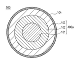
- FIG. 1 is a schematic diagram of a coated optical fiber according to an embodiment of the present invention.
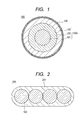
- FIG. 2 is a schematic diagram of an optical fiber ribbon according to an embodiment of the present invention.
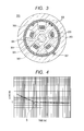
- FIG. 3 is a schematic diagram of an optical fiber cable according to an embodiment of the present invention.
- FIG. 4 is a graph showing the relationship between the load and the time taken until a glass fiber comes out of a primary coating layer.
- FIG. 5 is a schematic diagram of a load testing apparatus used for conducting a load test.
- FIG. 1 shows a schematic diagram of a coated optical fiber 100 according to the present embodiment.
- the coated optical fiber 100 includes: an optical fiber 100 a including a glass fiber 101 , a primary coating layer 102 coating an outer periphery of the glass fiber 101 , a secondary coating layer 103 coating an outer periphery of the primary coating layer 102 ; and a colored layer 104 coating an outer periphery of the optical fiber 100 a.
- Each of the primary coating layer 102 , the secondary coating layer 103 , and the colored layer 104 is made from a coating material adjusted to have predetermined characteristics.
- an ultraviolet ray curable resin is used, in general.
- the ultraviolet ray curable resin contains at least an oligomer, a diluent monomer, and a photo-polymerization initiator, and further contains additives such as a silane coupling agent and a chain transfer agent for adjusting various properties.
- the coating materials of the layers be adjusted so that the primary coating layer 102 can have a low elastic modulus and the secondary coating layer 103 can have a high elastic modulus.
- the primary coating layer 102 serves as a soft buffer layer
- the secondary coating layer 103 functions as a hard protective layer.
- increase in transmission loss can be suppressed even when an external force is applied to the optical fiber 100 a .
- the elastic modulus of the primary coating layer 102 is preferably 0.2 to 3 MPa
- the elastic modulus of the secondary coating layer 103 is preferably 500 to 1200 MPa
- the elastic modulus of the colored layer 104 is preferably 100 to 2000 MPa.
- the coating material for the colored layer 104 is colored with a dye or a pigment for visibility.
- the colored layer 104 does not necessarily have to be colored, and a non-colored tertiary coating layer for strength retention and the like is also acceptable.
- coated optical fibers of a type in which the primary coating layer 102 or the secondary coating layer 103 is colored with a dye or a pigment and the colored layer 104 is not provided for cost reduction are gaining popularity.
- a ribbon coating layer used for forming an optical fiber ribbon by arranging the coated optical fibers in parallel to each other and coating the coated optical fibers together acts as the tertiary coating layer.
- soluble components in the coating layers are dissolved into water accumulated in the peeled portion between the glass fiber and the primary coating layer to form an aqueous solution.
- the colored layer acts as a semipermeable membrane. An osmotic pressure is generated because of the difference in concentration between the aqueous solution in the interlayer peeling portion and water outside the colored layer, and water moves to the interlayer peeling portion because of the osmotic pressure. As a result, the interlayer peeling may grow.
- the transmission loss may increase remarkably in a coated optical fiber having a colored layer.
- the glass fiber 101 has a diameter of 90 to 150 ⁇ m and preferably about 125 ⁇ m
- each of the primary coating layer 102 and the secondary coating layer 103 has a thickness of 10 to 60 ⁇ m and preferably 20 to 50 ⁇ m
- the colored layer 104 has a thickness of 5 to 20 ⁇ m.
- the sizes of these layers are not limited to these values, and can be changed to any values.
- FIG. 2 shows a schematic diagram of an optical fiber ribbon 200 having such a structure.
- the optical fiber ribbon 200 has a structure in which the outside of four coated optical fibers 100 arranged in parallel to each other is coated with an ribbon coating layer 201 .
- the ribbon coating layer 201 preferably has an elastic modulus of 100 to 2000 MPa from the viewpoints of strength retention and the like.
- the size of the optical fiber ribbon 200 is about 320 ⁇ m in thickness and 1.1 mm in width.
- the size of the optical fiber ribbon 200 and the number of the coated optical fibers 100 are not limited to these values, and may be changed to any values.
- the optical fibers 100 a may be used instead of the coated optical fibers 100 to form the optical fiber ribbon 200 .
- the optical fiber ribbon 200 has a structure in which the outside of the secondary coating layers 103 of the optical fibers 100 a is coated with an ribbon coating layer 201 serving as a tertiary coating layer.
- an optical fiber cable may be formed by housing multiple optical fiber ribbons 200 in a slot.
- FIG. 3 shows a schematic diagram of an optical fiber cable 300 having such a structure.
- the optical fiber cable 300 is, for example, an SZ cable including 40 fibers.
- the optical fiber cable 300 includes a spacer 301 having five SZ slots 302 .
- Two optical fiber ribbons 200 are housed in each of the SZ slots 302 .
- a pressing and wrapping tape 303 is wound around the spacer 301 , and the outside of the pressing and wrapping tape 303 is covered with a sheath 304 .
- a tension member 305 is provided at a center in a cross section of the spacer 301 .
- Tracer marks 306 are provided on an outer periphery of the spacer 301 .
- a ripcord 307 is provided on a part of an outer periphery of the pressing and wrapping tape 303 .
- the SZ slots 302 are not limited to the five-grooved type, and the number of the groves can be selected as appropriate. Moreover, the number of the optical fiber ribbons 200 in each SZ slot 302 is not limited to two, but can be selected as appropriate. In addition, S slots may be used instead of the SZ slots.
- the elastic modulus (also referred to as Young's modulus) is used as an index of the hardness of each of the coating layers.
- the elastic modulus is measured for each of the coating layer after an optical fiber is fabricated.
- a well-known approach may be employed as a specific approach for measuring the elastic modulus.
- a limit-adhesion strength is an index indicative of the adhesion strength of an interface between a glass fiber and a primary coating layer in a hot and humid environment.
- the limit-adhesion strength is defined as follows. Note that the definition of the limit-adhesion strength is based on the description in Patent Document 3.
- a coated optical fiber whose coating layers are nicked over the entire periphery at a position 10 mm away from an end is prepared while only the glass fiber is left intact. Then, the coating layer in a region ranging from the end of the coated optical fiber to a position 10 mm away from the end is fixed to sandpaper by an adhesive agent. The sandpaper is fixed in an atmosphere of a temperature of 60° C. and a humidity of 98% RH with the end of the coated optical fiber located on the upper side. Then, a weight is attached to the other end of the coated optical fiber. Thus, a constant load is applied between the glass fiber and the primary coating layer in the portion extending above the nick over a length of 10 mm.
- the time taken until the glass fiber comes out of the primary coating layer is measured. Then, the load applied to the glass fiber, i.e., the mass of the weight is gradually changed, and the relationship between the load and the time taken until the glass fiber comes out is found.
- FIG. 4 shows an example of a typical measurement result of the limit-adhesion strength.
- FIG. 4 is a graph shown as an example to help the definition of the limit-adhesion strength to be understood.
- FIG. 4 does not show a result of a specific example of this embodiment carried out and that specific numeric values on the vertical axis and the horizontal axis are omitted.
- An inflection point D exists at which the time taken until the glass fiber comes out suddenly increases and the slope becomes gentle as described above.
- the load C at the inflection point D at which the slope becomes gentle is defined as the limit-adhesion strength.
- Patent Document 3 shows that the higher the limit-adhesion strength is, the more the increase in transmission loss is reduced after immersion in hot water.
- peeling at the glass/primary interface is referred to as delamination
- tearing inside the primary coating layer or void formation in the primary coating layer is referred to as tearing.
- Susceptibility to delamination and susceptibility to tearing are presumably associated with susceptibility to peeling at the glass/primary interface and susceptibility to water bubble formation.
- D50 and T50 are defined as follows, respectively.
- FIG. 5 shows a schematic diagram of a load testing apparatus 900 as an example of an apparatus for measuring the delamination and the tearing.
- the load testing apparatus 900 includes a stage 901 on which a coated optical fiber 100 to be measured is to be mounted, a load unit 902 being provided away from the stage 901 and capable of adjusting the value of the load, a rod 903 fixed to the load unit 902 on the stage 901 side, and a driving unit 904 capable of moving the load unit 902 and the rod 903 in a normal line direction A of the stage 901 .
- the rod 903 is provided to be perpendicular to the longitudinal direction of the coated optical fiber 100 in a state of being mounted on the stage 901 and in parallel to a surface of the stage 901 .
- the driving unit 904 releases the load unit 902 , the load unit 902 and the rod 903 move by their own weights toward the stage 901 .
- the rod 903 and the stage 901 sandwiches the coated optical fiber 100 , and the load unit 902 applies a load to a point B on the coated optical fiber 100 .
- the driving unit 904 moves the load unit 902 and the rod 903 in the direction away from the coated optical fiber 100 , and the load unit 902 does not apply a load to the coated optical fiber 100 anymore.
- the measuring apparatus is not limited to that having the apparatus structure of FIG. 5 , as long as a predetermined load can be applied for a predetermined time to a point B of the coated optical fiber 100 in a direction perpendicular to the longitudinal direction of the coated optical fiber.
- a coated optical fiber 100 to be measured is fixed to the load testing apparatus 900 . Then, a predetermined load is applied to a point for 4.5 seconds, and further the load is applied repeatedly to 30 points at intervals of approximately 6 mm. After that, the presence or absence of delamination or tearing is observed for each of the points with an optical microscope. Moreover, the load is increased, and application of the load to 30 points different from those in the prior observation and observation of the points are repeated every time the load is increased. Based on this, the value of the load and the number of points where the delamination or tear occurs are plotted against each other. Note that the points to which the load is applied is not limited to 30.
- a smallest load with which delamination or tearing is observed at 50% or more of all the points to which the load is applied is defined as D50 or T50.
- a smallest load with which delamination is observed at 50% (15 points) or more of the 30 points to which the load is applied is defined as D50.
- a smallest load with which tearing is observed at 50% (15 points) or more of the 30 points to which the load is applied is defined as D50.
- D50 indicates that a smaller load is required to cause delamination, i.e., a smaller D50 indicates a higher susceptibility to delamination.
- T50 indicates that a smaller load is required to cause tearing, i.e., a smaller T50 indicates a higher susceptibility to tearing.
- D50 and T50 can be used as indices of susceptibilities to delamination and tearing, respectively.
- each coating layer is adjusted as follows.
- the present inventors have found that water bubbles are formed evenly in the primary coating layer during immersion in hot water by making the tearing more likely to occur than the delamination, so that the increase in transmission loss can be reduced.
- the tearing is more likely to occur than the delamination, in other words, when the D50 is greater than the T50, a stress from the secondary coating layer causes formation of water bubbles inside the primary coating layer before delamination during immersion in hot water. Presumably, as a result of this, the stress is relaxed by the water bubbles, so that the increase in transmission loss can be reduced.
- an external force transmitted to the glass/primary interface is relaxed by decreasing the elastic modulus of the primary coating layer and increasing the elastic modulus of the secondary coating layer.
- the adhesion strength between the surface of the glass fiber and the primary coating layer is increased by adding an additive such as a silane coupling agent, for example, to the material of the primary coating layer.
- the elastic modulus of the primary coating layer is decreased, i.e., the crosslink density of the primary coating layer is decreased.
- a hydrophobic oligomer such as polytetramethylene glycol (PTMG) as a material for the primary coating layer and to adjust water absorption by adding a hydrophilic monomer such as acrylamide.
- PTMG polytetramethylene glycol
- a coated optical fiber in which water bubbles are formed evenly in the primary coating layer during immersion in hot water can be obtained by conducting, in an integrated manner, the adjustment of the materials for the coating layers so that the D50 and the T50 can take predetermined values and the adjustment of the mixing ratio of the hydrophobic substance and the hydrophilic substance in the material for the primary coating layer so that water bubbles can be distributed uniformly.
- Examples 1 to 4 and Comparative Examples 1 to 3 were prepared which were optical fiber ribbons having the structure shown in FIG. 2 and among which properties of the coating layers were varied.
- the coated optical fibers were taken out from the optical fiber ribbons, and the above-described elastic modulus, D50, T50, and limit-adhesion strength were measured.
- the transmission loss before immersion in hot water was measured by using the optical fiber ribbons.
- Examples and Comparative Examples were immersed in hot water at 60° C. for 200 days, and then the water bubbles were observed and the transmission loss was measured.
- Table 1 shows the results of the observation and measurement carried out.
- an approximately 10-cm piece was cut out of the coated optical fiber. Then, three points (3 cm, 6 cm, and 9 cm) away from an end of the coated optical fiber at intervals of approximately 3 cm were observed. Further, the coated optical fiber was rotated by 90 degrees in the circumferential direction of the cross-section, and the three points were observed again.
- the presence or absence of generation of the delamination and the number and the sizes of the water bubbles were observed and measured in a direction perpendicular to the longitudinal direction of the coated optical fiber in an area of 30 ⁇ m in the thickness direction and 30 ⁇ m in the longitudinal direction in the primary coating layer (since the thickness of the primary coating layer is 30 ⁇ m, this area is referred to as a unit area defined with the thickness of the primary coating layer being taken as one unit).
- This measurement makes it possible to determine whether or not the water bubbles are evenly formed not only in the longitudinal direction of the coated optical fiber but also in the circumferential direction of the cross-section.
- the delamination was determined to be present if one or more delaminations at the glass/primary interface occurred at any of the six observation points, and the delamination was determined to be absent if no delamination occurred.
- the maximum number of fine bubbles represents the largest number of water bubbles among those observed at the six observation points. Meanwhile, the minimum number of fine bubbles represents the smallest number of water bubbles among those observed at the six observation points. In a case where the number of water bubbles was greater than 10, the maximum number is expressed as “>10”.
- the maximum diameter of fine bubbles represents the diameter of the largest water bubble in the six observation points. Note that when the water bubble had an elliptical shape, the longest distance passing through the center of the water bubble was employed as the diameter of the water bubble. When the diameter of the water bubble was larger than 10 ⁇ m, the maximum diameter is expressed as “>10”.
- the transmission loss of each of Examples and Comparative Examples was measured before and after the immersion in hot water.
- the increase in transmission loss was an increment in transmission loss between that measured by using the coated optical fiber after the immersion in hot water at 60° C. for 200 days and that measured by using the coated optical fiber before the immersion in hot water.
- light with a wavelength of 1.55 ⁇ m was used.
- an increase in transmission loss of less than 0.1 dB/km is regarded as being acceptable in a practical sense. For this reason, if the increase was 0.1 dB/km or more, the water resistance was evaluated to be insufficient (this evaluation was represented by C); if the increase was less than 0.1 dB/km, the water resistance was evaluated to be sufficient (this evaluation was represented by B); and further if the increase was less than 0.07 dB/km, the water resistance was evaluated to be excellent (this evaluation was represented by A).
- the water bubbles were formed substantially evenly in the primary coating layer.
- the stress from the secondary coating layer to the glass/primary interface was relaxed by the generation of small water bubbles substantially evenly in the primary coating layer during the immersion in hot water at 60° C. for 200 days, so that the increase in transmission loss was reduced.
- the increase in transmission loss was reduced when the water bubbles were formed substantially evenly in the primary coating layer, the sizes of the water bubbles were 10 ⁇ m or less in diameter, and the number of the water bubbles present per unit area on the cross-section taken along the longitudinal direction of the primary coating layer was one or more.
- the unit area is defined as an area equal to the square of the thickness of the primary coating layer.
Landscapes
- Physics & Mathematics (AREA)
- General Physics & Mathematics (AREA)
- Optics & Photonics (AREA)
- Optical Fibers, Optical Fiber Cores, And Optical Fiber Bundles (AREA)
- Surface Treatment Of Glass Fibres Or Filaments (AREA)
Applications Claiming Priority (3)
| Application Number | Priority Date | Filing Date | Title |
|---|---|---|---|
| JP2012033088A JP5465741B2 (ja) | 2012-02-17 | 2012-02-17 | 光ファイバ心線、光ファイバテープ心線および光ケーブル |
| JP2012-033088 | 2012-02-17 | ||
| PCT/JP2012/008037 WO2013121494A1 (ja) | 2012-02-17 | 2012-12-17 | 光ファイバ心線、光ファイバテープ心線および光ケーブル |
Related Parent Applications (1)
| Application Number | Title | Priority Date | Filing Date |
|---|---|---|---|
| PCT/JP2012/008037 Continuation WO2013121494A1 (ja) | 2012-02-17 | 2012-12-17 | 光ファイバ心線、光ファイバテープ心線および光ケーブル |
Publications (2)
| Publication Number | Publication Date |
|---|---|
| US20150293325A1 US20150293325A1 (en) | 2015-10-15 |
| US9846292B2 true US9846292B2 (en) | 2017-12-19 |
Family
ID=48983663
Family Applications (1)
| Application Number | Title | Priority Date | Filing Date |
|---|---|---|---|
| US14/296,003 Expired - Fee Related US9846292B2 (en) | 2012-02-17 | 2014-06-04 | Coated optical fiber, optical fiber ribbon, and optical cable |
Country Status (7)
| Country | Link |
|---|---|
| US (1) | US9846292B2 (enExample) |
| EP (1) | EP2816384A4 (enExample) |
| JP (1) | JP5465741B2 (enExample) |
| CN (1) | CN104115049B (enExample) |
| BR (1) | BR112014019240A8 (enExample) |
| IN (1) | IN2014CN04882A (enExample) |
| WO (1) | WO2013121494A1 (enExample) |
Families Citing this family (7)
| Publication number | Priority date | Publication date | Assignee | Title |
|---|---|---|---|---|
| JP6569429B2 (ja) * | 2015-09-25 | 2019-09-04 | 住友電気工業株式会社 | 光ファイバテープ心線 |
| US10838159B2 (en) | 2016-09-30 | 2020-11-17 | Fujikura Ltd. | Optical fiber colored core wire, optical fiber cable, and method of manufacturing optical fiber colored core wire |
| KR102326802B1 (ko) * | 2016-09-30 | 2021-11-15 | 가부시키가이샤후지쿠라 | 광섬유 리본, 광섬유 케이블, 및 광섬유 리본의 제조 방법 |
| US10451795B2 (en) * | 2017-11-16 | 2019-10-22 | Ofs Fitel, Llc | Optical fiber for applications requiring high system optical signal-to-noise ratio performance and low degradation from nonlinear impairments |
| WO2019139018A1 (ja) * | 2018-01-10 | 2019-07-18 | 住友電気工業株式会社 | 光ファイバケーブルおよび光ファイバケーブルの製造方法 |
| JP7331960B2 (ja) * | 2020-02-13 | 2023-08-23 | 日本電信電話株式会社 | 光ファイバのマイクロベンドを検知する装置及び方法 |
| US20230236356A1 (en) * | 2022-01-25 | 2023-07-27 | Corning Research & Development Corporation | Single-mode optical fiber with dyed thin coating |
Citations (23)
| Publication number | Priority date | Publication date | Assignee | Title |
|---|---|---|---|---|
| JPH06109955A (ja) | 1992-09-25 | 1994-04-22 | Mitsubishi Cable Ind Ltd | 超多心ケーブル用高密度テープ心線 |
| JPH06128525A (ja) | 1992-10-14 | 1994-05-10 | Dainippon Ink & Chem Inc | 光ファイバ一次被覆用紫外線硬化型樹脂組成物 |
| JP2004054138A (ja) | 2002-07-23 | 2004-02-19 | Furukawa Electric Co Ltd:The | 光ファイバ心線 |
| CN2869902Y (zh) | 2006-03-09 | 2007-02-14 | 深圳市特发信息股份有限公司光缆分公司 | 骨架式光纤带光缆 |
| JP2008040369A (ja) | 2006-08-10 | 2008-02-21 | Furukawa Electric Co Ltd:The | 光ファイバ |
| CN101228468A (zh) | 2006-08-10 | 2008-07-23 | 古河电气工业株式会社 | 光纤 |
| JP2008197258A (ja) | 2007-02-09 | 2008-08-28 | Sumitomo Electric Ind Ltd | 光ケーブル |
| US20090022461A1 (en) * | 2007-03-08 | 2009-01-22 | The Furukawa Electric Co., Ltd. | Optical fiber |
| US20090052847A1 (en) | 2007-08-22 | 2009-02-26 | Furukawa Electric Co., Ltd. | Optical fiber ribbon |
| CN101463114A (zh) | 2002-03-27 | 2009-06-24 | Dsmip财产有限公司 | 可固化液态树脂组合物 |
| US7555183B2 (en) | 2006-03-31 | 2009-06-30 | The Furukawa Electric Co., Ltd. | Optical fiber ribbon core and optical fiber cable |
| US20100119198A1 (en) * | 2008-03-14 | 2010-05-13 | Furukawa Electric Co., Ltd. | Coated optical fibers |
| US7729564B2 (en) | 2006-07-28 | 2010-06-01 | The Furukawa Electric Co., Ltd. | Optical fiber provided with reliable coating layers |
| JP2010217800A (ja) | 2009-03-19 | 2010-09-30 | Furukawa Electric Co Ltd:The | 光ファイバ |
| US20100322572A1 (en) | 2007-02-08 | 2010-12-23 | Itaru Sakabe | Optical cable |
| US7978948B2 (en) | 2006-09-08 | 2011-07-12 | The Furukawa Electric Co., Ltd. | Optical fiber and optical fiber ribbon |
| US20110274396A1 (en) | 2009-12-17 | 2011-11-10 | Furukawa Electric Co., Ltd. | Optical fiber |
| US20120189257A1 (en) | 2010-07-22 | 2012-07-26 | Furukawa Electric Co., Ltd. | Optical fiber, optical fiber ribbon and optical fiber cable |
| US20130315545A1 (en) | 2011-02-04 | 2013-11-28 | Furukawa Electric Co., Ltd. | Optical fiber |
| US8639077B2 (en) | 2010-11-24 | 2014-01-28 | Furukawa Electric Co., Ltd. | Colored coated optical fiber |
| US8658257B2 (en) | 2010-01-19 | 2014-02-25 | Furukawa Electric Co., Ltd. | Method of manufacturing optical fiber |
| US8693832B2 (en) | 2010-07-07 | 2014-04-08 | Furukawa Electric Co., Ltd. | Optical fiber |
| US20140226941A1 (en) | 2012-02-15 | 2014-08-14 | Furukawa Electric Co., Ltd. | Colored optical fiber, optical fiber ribbon, and optical fiber cable |
Family Cites Families (5)
| Publication number | Priority date | Publication date | Assignee | Title |
|---|---|---|---|---|
| JP2004212722A (ja) * | 2003-01-06 | 2004-07-29 | Fuji Photo Film Co Ltd | 光学部材、その製造に用いられる重合性組成物及び製造方法、並びにそれを用いた光通信システム |
| US7400808B2 (en) * | 2003-01-10 | 2008-07-15 | The Furukawa Electric Co., Ltd. | Optical fiber, light amplifier, and light source |
| JP2005316235A (ja) * | 2004-04-30 | 2005-11-10 | Fujikura Ltd | 光ファイバ心線、光ファイバテープ心線、光ファイバケーブル、及び光ファイバドロップケーブル |
| JP2007333795A (ja) * | 2006-06-12 | 2007-12-27 | Furukawa Electric Co Ltd:The | 光ファイバ心線及びその製造方法 |
| JP2009181119A (ja) * | 2008-01-29 | 2009-08-13 | Sumitomo Electric Ind Ltd | 光ケーブル |
-
2012
- 2012-02-17 JP JP2012033088A patent/JP5465741B2/ja not_active Expired - Fee Related
- 2012-12-17 WO PCT/JP2012/008037 patent/WO2013121494A1/ja not_active Ceased
- 2012-12-17 EP EP12868568.2A patent/EP2816384A4/en not_active Withdrawn
- 2012-12-17 CN CN201280069889.8A patent/CN104115049B/zh not_active Expired - Fee Related
- 2012-12-17 IN IN4882CHN2014 patent/IN2014CN04882A/en unknown
- 2012-12-17 BR BR112014019240A patent/BR112014019240A8/pt not_active Application Discontinuation
-
2014
- 2014-06-04 US US14/296,003 patent/US9846292B2/en not_active Expired - Fee Related
Patent Citations (29)
| Publication number | Priority date | Publication date | Assignee | Title |
|---|---|---|---|---|
| JPH06109955A (ja) | 1992-09-25 | 1994-04-22 | Mitsubishi Cable Ind Ltd | 超多心ケーブル用高密度テープ心線 |
| JPH06128525A (ja) | 1992-10-14 | 1994-05-10 | Dainippon Ink & Chem Inc | 光ファイバ一次被覆用紫外線硬化型樹脂組成物 |
| CN101463114A (zh) | 2002-03-27 | 2009-06-24 | Dsmip财产有限公司 | 可固化液态树脂组合物 |
| JP2004054138A (ja) | 2002-07-23 | 2004-02-19 | Furukawa Electric Co Ltd:The | 光ファイバ心線 |
| CN2869902Y (zh) | 2006-03-09 | 2007-02-14 | 深圳市特发信息股份有限公司光缆分公司 | 骨架式光纤带光缆 |
| US7555183B2 (en) | 2006-03-31 | 2009-06-30 | The Furukawa Electric Co., Ltd. | Optical fiber ribbon core and optical fiber cable |
| US7729564B2 (en) | 2006-07-28 | 2010-06-01 | The Furukawa Electric Co., Ltd. | Optical fiber provided with reliable coating layers |
| US8111964B2 (en) | 2006-08-10 | 2012-02-07 | The Furukawa Electric Co., Ltd. | Optical fiber |
| US20100046900A1 (en) * | 2006-08-10 | 2010-02-25 | The Furukawa Electric Co., Ltd. | Optical Fiber |
| CN101228468A (zh) | 2006-08-10 | 2008-07-23 | 古河电气工业株式会社 | 光纤 |
| JP2008040369A (ja) | 2006-08-10 | 2008-02-21 | Furukawa Electric Co Ltd:The | 光ファイバ |
| US7978948B2 (en) | 2006-09-08 | 2011-07-12 | The Furukawa Electric Co., Ltd. | Optical fiber and optical fiber ribbon |
| US20100322572A1 (en) | 2007-02-08 | 2010-12-23 | Itaru Sakabe | Optical cable |
| US8184937B2 (en) | 2007-02-08 | 2012-05-22 | Sumitomo Electric Industries, Ltd. | Optical cable |
| JP2008197258A (ja) | 2007-02-09 | 2008-08-28 | Sumitomo Electric Ind Ltd | 光ケーブル |
| US20090022461A1 (en) * | 2007-03-08 | 2009-01-22 | The Furukawa Electric Co., Ltd. | Optical fiber |
| US20090052847A1 (en) | 2007-08-22 | 2009-02-26 | Furukawa Electric Co., Ltd. | Optical fiber ribbon |
| US20100119198A1 (en) * | 2008-03-14 | 2010-05-13 | Furukawa Electric Co., Ltd. | Coated optical fibers |
| JP2010217800A (ja) | 2009-03-19 | 2010-09-30 | Furukawa Electric Co Ltd:The | 光ファイバ |
| US20100266257A1 (en) | 2009-03-19 | 2010-10-21 | Furukawa Electric Co., Ltd. | Optical fibers |
| US8731365B1 (en) | 2009-03-19 | 2014-05-20 | Furukawa Electric Co., Ltd. | Optical fibers |
| US20110274396A1 (en) | 2009-12-17 | 2011-11-10 | Furukawa Electric Co., Ltd. | Optical fiber |
| US8571372B2 (en) | 2009-12-17 | 2013-10-29 | Furukawa Electric Co., Ltd. | Optical fiber |
| US8658257B2 (en) | 2010-01-19 | 2014-02-25 | Furukawa Electric Co., Ltd. | Method of manufacturing optical fiber |
| US8693832B2 (en) | 2010-07-07 | 2014-04-08 | Furukawa Electric Co., Ltd. | Optical fiber |
| US20120189257A1 (en) | 2010-07-22 | 2012-07-26 | Furukawa Electric Co., Ltd. | Optical fiber, optical fiber ribbon and optical fiber cable |
| US8639077B2 (en) | 2010-11-24 | 2014-01-28 | Furukawa Electric Co., Ltd. | Colored coated optical fiber |
| US20130315545A1 (en) | 2011-02-04 | 2013-11-28 | Furukawa Electric Co., Ltd. | Optical fiber |
| US20140226941A1 (en) | 2012-02-15 | 2014-08-14 | Furukawa Electric Co., Ltd. | Colored optical fiber, optical fiber ribbon, and optical fiber cable |
Non-Patent Citations (6)
| Title |
|---|
| Charles Aloisio, et al., "Optical Fiber Coating Delamination Using Model Coating Materials" Proceedings of the 51st IWCS, 2002, pp. 738-747. |
| Combined Office Action and Search Report issued Jan. 18, 2017 in Chinese Patent Application No. 201280069889.8 (with English translation). |
| International Search Report mailed Mar. 19, 2013 for PCT/JP2012/008037 filed on Dec. 17, 2012 with English Translation. |
| International Written Opinion mailed Mar. 19, 2013 for PCT/JP2012/008037 filed on Dec. 17, 2012. |
| Saito et al., translation of JP 2004-054138, Feb. 19, 2004. * |
| U.S. Appl. No. 14/309,380, filed Jun. 19, 2014, Tanaka, et al. |
Also Published As
| Publication number | Publication date |
|---|---|
| BR112014019240A8 (pt) | 2017-07-11 |
| US20150293325A1 (en) | 2015-10-15 |
| CN104115049B (zh) | 2018-01-02 |
| JP2013171072A (ja) | 2013-09-02 |
| CN104115049A (zh) | 2014-10-22 |
| EP2816384A1 (en) | 2014-12-24 |
| IN2014CN04882A (enExample) | 2015-09-18 |
| EP2816384A4 (en) | 2015-11-11 |
| JP5465741B2 (ja) | 2014-04-09 |
| BR112014019240A2 (enExample) | 2017-06-20 |
| WO2013121494A1 (ja) | 2013-08-22 |
Similar Documents
| Publication | Publication Date | Title |
|---|---|---|
| US9846292B2 (en) | Coated optical fiber, optical fiber ribbon, and optical cable | |
| US7050688B2 (en) | Fiber optic articles, assemblies, and cables having optical waveguides | |
| US8682123B2 (en) | Adhesively coupled optical fibers and enclosing tape | |
| CN100430767C (zh) | 具有优先分离顺序的光纤带 | |
| DK2204681T3 (en) | An optical fiber cable, comprising a perforated water-blocking element | |
| US6714713B2 (en) | Optical fiber having a low-shrink buffer layer and methods of manufacturing the same | |
| CN103765272B (zh) | 光纤着色芯线、光纤带芯线以及光缆 | |
| US9291769B2 (en) | Colored optical fiber, optical fiber ribbon and optical fiber cable, using colored optical fiber | |
| JP4865891B1 (ja) | 光ファイバ素線、光ファイバテープ心線および光ファイバケーブル | |
| US20150192734A1 (en) | Optical fiber and optical fiber cable | |
| EP3715926B1 (en) | Optical cables with lubricated optical fibers and methods of formation thereof | |
| CN101542347B (zh) | 光纤芯线 | |
| US9025924B2 (en) | Optical fiber | |
| EP3049843A1 (en) | Stretchable fiber optic cable | |
| CN100399090C (zh) | 具有优先拉扯部分的光纤带 | |
| JP6067332B2 (ja) | 光ファイバテープ心線 | |
| JP5202943B2 (ja) | 光ファイバ | |
| JP2010217800A (ja) | 光ファイバ | |
| WO2020054753A1 (ja) | 光ファイバ心線及び光ファイバケーブル | |
| US10393975B2 (en) | Optical cable with retractable modules and a method for producing said modules | |
| US6618527B2 (en) | Fiber optic cables having grease layers with reduced agglomerate sizes | |
| JP2005321645A (ja) | テープ型光ファイバ心線 | |
| WO2021187514A1 (ja) | 光ファイバ心線、光ファイバケーブル及び光ファイバテープ心線 | |
| JP2001100067A (ja) | 光ファイバテープ心線及び光ファイバケーブル |
Legal Events
| Date | Code | Title | Description |
|---|---|---|---|
| AS | Assignment |
Owner name: FURUKAWA ELECTRIC CO., LTD., JAPAN Free format text: ASSIGNMENT OF ASSIGNORS INTEREST;ASSIGNORS:KASAHARA, MINORU;SAITO, MINORU;ARASHITANI, YOSHIHIRO;SIGNING DATES FROM 20140711 TO 20140717;REEL/FRAME:033606/0151 |
|
| STCF | Information on status: patent grant |
Free format text: PATENTED CASE |
|
| FEPP | Fee payment procedure |
Free format text: MAINTENANCE FEE REMINDER MAILED (ORIGINAL EVENT CODE: REM.); ENTITY STATUS OF PATENT OWNER: LARGE ENTITY |
|
| LAPS | Lapse for failure to pay maintenance fees |
Free format text: PATENT EXPIRED FOR FAILURE TO PAY MAINTENANCE FEES (ORIGINAL EVENT CODE: EXP.); ENTITY STATUS OF PATENT OWNER: LARGE ENTITY |
|
| STCH | Information on status: patent discontinuation |
Free format text: PATENT EXPIRED DUE TO NONPAYMENT OF MAINTENANCE FEES UNDER 37 CFR 1.362 |
|
| FP | Lapsed due to failure to pay maintenance fee |
Effective date: 20211219 |