US9821679B2 - Method for the diagnosis of the offset of the resolver of an electric machine - Google Patents
Method for the diagnosis of the offset of the resolver of an electric machine Download PDFInfo
- Publication number
- US9821679B2 US9821679B2 US14/823,601 US201514823601A US9821679B2 US 9821679 B2 US9821679 B2 US 9821679B2 US 201514823601 A US201514823601 A US 201514823601A US 9821679 B2 US9821679 B2 US 9821679B2
- Authority
- US
- United States
- Prior art keywords
- axis
- resolver
- minimum reluctance
- current
- offset
- Prior art date
- Legal status (The legal status is an assumption and is not a legal conclusion. Google has not performed a legal analysis and makes no representation as to the accuracy of the status listed.)
- Active
Links
Images


Classifications
-
- B—PERFORMING OPERATIONS; TRANSPORTING
- B60—VEHICLES IN GENERAL
- B60L—PROPULSION OF ELECTRICALLY-PROPELLED VEHICLES; SUPPLYING ELECTRIC POWER FOR AUXILIARY EQUIPMENT OF ELECTRICALLY-PROPELLED VEHICLES; ELECTRODYNAMIC BRAKE SYSTEMS FOR VEHICLES IN GENERAL; MAGNETIC SUSPENSION OR LEVITATION FOR VEHICLES; MONITORING OPERATING VARIABLES OF ELECTRICALLY-PROPELLED VEHICLES; ELECTRIC SAFETY DEVICES FOR ELECTRICALLY-PROPELLED VEHICLES
- B60L15/00—Methods, circuits, or devices for controlling the traction-motor speed of electrically-propelled vehicles
- B60L15/02—Methods, circuits, or devices for controlling the traction-motor speed of electrically-propelled vehicles characterised by the form of the current used in the control circuit
- B60L15/025—Methods, circuits, or devices for controlling the traction-motor speed of electrically-propelled vehicles characterised by the form of the current used in the control circuit using field orientation; Vector control; Direct Torque Control [DTC]
-
- B—PERFORMING OPERATIONS; TRANSPORTING
- B60—VEHICLES IN GENERAL
- B60L—PROPULSION OF ELECTRICALLY-PROPELLED VEHICLES; SUPPLYING ELECTRIC POWER FOR AUXILIARY EQUIPMENT OF ELECTRICALLY-PROPELLED VEHICLES; ELECTRODYNAMIC BRAKE SYSTEMS FOR VEHICLES IN GENERAL; MAGNETIC SUSPENSION OR LEVITATION FOR VEHICLES; MONITORING OPERATING VARIABLES OF ELECTRICALLY-PROPELLED VEHICLES; ELECTRIC SAFETY DEVICES FOR ELECTRICALLY-PROPELLED VEHICLES
- B60L3/00—Electric devices on electrically-propelled vehicles for safety purposes; Monitoring operating variables, e.g. speed, deceleration or energy consumption
- B60L3/0023—Detecting, eliminating, remedying or compensating for drive train abnormalities, e.g. failures within the drive train
- B60L3/0038—Detecting, eliminating, remedying or compensating for drive train abnormalities, e.g. failures within the drive train relating to sensors
-
- B—PERFORMING OPERATIONS; TRANSPORTING
- B60—VEHICLES IN GENERAL
- B60L—PROPULSION OF ELECTRICALLY-PROPELLED VEHICLES; SUPPLYING ELECTRIC POWER FOR AUXILIARY EQUIPMENT OF ELECTRICALLY-PROPELLED VEHICLES; ELECTRODYNAMIC BRAKE SYSTEMS FOR VEHICLES IN GENERAL; MAGNETIC SUSPENSION OR LEVITATION FOR VEHICLES; MONITORING OPERATING VARIABLES OF ELECTRICALLY-PROPELLED VEHICLES; ELECTRIC SAFETY DEVICES FOR ELECTRICALLY-PROPELLED VEHICLES
- B60L3/00—Electric devices on electrically-propelled vehicles for safety purposes; Monitoring operating variables, e.g. speed, deceleration or energy consumption
- B60L3/0023—Detecting, eliminating, remedying or compensating for drive train abnormalities, e.g. failures within the drive train
- B60L3/0061—Detecting, eliminating, remedying or compensating for drive train abnormalities, e.g. failures within the drive train relating to electrical machines
-
- B—PERFORMING OPERATIONS; TRANSPORTING
- B60—VEHICLES IN GENERAL
- B60L—PROPULSION OF ELECTRICALLY-PROPELLED VEHICLES; SUPPLYING ELECTRIC POWER FOR AUXILIARY EQUIPMENT OF ELECTRICALLY-PROPELLED VEHICLES; ELECTRODYNAMIC BRAKE SYSTEMS FOR VEHICLES IN GENERAL; MAGNETIC SUSPENSION OR LEVITATION FOR VEHICLES; MONITORING OPERATING VARIABLES OF ELECTRICALLY-PROPELLED VEHICLES; ELECTRIC SAFETY DEVICES FOR ELECTRICALLY-PROPELLED VEHICLES
- B60L3/00—Electric devices on electrically-propelled vehicles for safety purposes; Monitoring operating variables, e.g. speed, deceleration or energy consumption
- B60L3/12—Recording operating variables ; Monitoring of operating variables
-
- G—PHYSICS
- G01—MEASURING; TESTING
- G01D—MEASURING NOT SPECIALLY ADAPTED FOR A SPECIFIC VARIABLE; ARRANGEMENTS FOR MEASURING TWO OR MORE VARIABLES NOT COVERED IN A SINGLE OTHER SUBCLASS; TARIFF METERING APPARATUS; MEASURING OR TESTING NOT OTHERWISE PROVIDED FOR
- G01D5/00—Mechanical means for transferring the output of a sensing member; Means for converting the output of a sensing member to another variable where the form or nature of the sensing member does not constrain the means for converting; Transducers not specially adapted for a specific variable
- G01D5/12—Mechanical means for transferring the output of a sensing member; Means for converting the output of a sensing member to another variable where the form or nature of the sensing member does not constrain the means for converting; Transducers not specially adapted for a specific variable using electric or magnetic means
- G01D5/14—Mechanical means for transferring the output of a sensing member; Means for converting the output of a sensing member to another variable where the form or nature of the sensing member does not constrain the means for converting; Transducers not specially adapted for a specific variable using electric or magnetic means influencing the magnitude of a current or voltage
- G01D5/20—Mechanical means for transferring the output of a sensing member; Means for converting the output of a sensing member to another variable where the form or nature of the sensing member does not constrain the means for converting; Transducers not specially adapted for a specific variable using electric or magnetic means influencing the magnitude of a current or voltage by varying inductance, e.g. by a movable armature
- G01D5/204—Mechanical means for transferring the output of a sensing member; Means for converting the output of a sensing member to another variable where the form or nature of the sensing member does not constrain the means for converting; Transducers not specially adapted for a specific variable using electric or magnetic means influencing the magnitude of a current or voltage by varying inductance, e.g. by a movable armature by influencing the mutual induction between two or more coils
- G01D5/2073—Mechanical means for transferring the output of a sensing member; Means for converting the output of a sensing member to another variable where the form or nature of the sensing member does not constrain the means for converting; Transducers not specially adapted for a specific variable using electric or magnetic means influencing the magnitude of a current or voltage by varying inductance, e.g. by a movable armature by influencing the mutual induction between two or more coils by movement of a single coil with respect to two or more coils
-
- G—PHYSICS
- G01—MEASURING; TESTING
- G01D—MEASURING NOT SPECIALLY ADAPTED FOR A SPECIFIC VARIABLE; ARRANGEMENTS FOR MEASURING TWO OR MORE VARIABLES NOT COVERED IN A SINGLE OTHER SUBCLASS; TARIFF METERING APPARATUS; MEASURING OR TESTING NOT OTHERWISE PROVIDED FOR
- G01D5/00—Mechanical means for transferring the output of a sensing member; Means for converting the output of a sensing member to another variable where the form or nature of the sensing member does not constrain the means for converting; Transducers not specially adapted for a specific variable
- G01D5/12—Mechanical means for transferring the output of a sensing member; Means for converting the output of a sensing member to another variable where the form or nature of the sensing member does not constrain the means for converting; Transducers not specially adapted for a specific variable using electric or magnetic means
- G01D5/244—Mechanical means for transferring the output of a sensing member; Means for converting the output of a sensing member to another variable where the form or nature of the sensing member does not constrain the means for converting; Transducers not specially adapted for a specific variable using electric or magnetic means influencing characteristics of pulses or pulse trains; generating pulses or pulse trains
- G01D5/24471—Error correction
- G01D5/2448—Correction of gain, threshold, offset or phase control
-
- H02K11/0031—
-
- H—ELECTRICITY
- H02—GENERATION; CONVERSION OR DISTRIBUTION OF ELECTRIC POWER
- H02K—DYNAMO-ELECTRIC MACHINES
- H02K11/00—Structural association of dynamo-electric machines with electric components or with devices for shielding, monitoring or protection
- H02K11/20—Structural association of dynamo-electric machines with electric components or with devices for shielding, monitoring or protection for measuring, monitoring, testing, protecting or switching
- H02K11/21—Devices for sensing speed or position, or actuated thereby
- H02K11/225—Detecting coils
-
- H—ELECTRICITY
- H02—GENERATION; CONVERSION OR DISTRIBUTION OF ELECTRIC POWER
- H02P—CONTROL OR REGULATION OF ELECTRIC MOTORS, ELECTRIC GENERATORS OR DYNAMO-ELECTRIC CONVERTERS; CONTROLLING TRANSFORMERS, REACTORS OR CHOKE COILS
- H02P21/00—Arrangements or methods for the control of electric machines by vector control, e.g. by control of field orientation
- H02P21/24—Vector control not involving the use of rotor position or rotor speed sensors
- H02P21/32—Determining the initial rotor position
-
- H—ELECTRICITY
- H02—GENERATION; CONVERSION OR DISTRIBUTION OF ELECTRIC POWER
- H02P—CONTROL OR REGULATION OF ELECTRIC MOTORS, ELECTRIC GENERATORS OR DYNAMO-ELECTRIC CONVERTERS; CONTROLLING TRANSFORMERS, REACTORS OR CHOKE COILS
- H02P6/00—Arrangements for controlling synchronous motors or other dynamo-electric motors using electronic commutation dependent on the rotor position; Electronic commutators therefor
- H02P6/14—Electronic commutators
- H02P6/16—Circuit arrangements for detecting position
- H02P6/18—Circuit arrangements for detecting position without separate position detecting elements
- H02P6/183—Circuit arrangements for detecting position without separate position detecting elements using an injected high frequency signal
-
- B—PERFORMING OPERATIONS; TRANSPORTING
- B60—VEHICLES IN GENERAL
- B60L—PROPULSION OF ELECTRICALLY-PROPELLED VEHICLES; SUPPLYING ELECTRIC POWER FOR AUXILIARY EQUIPMENT OF ELECTRICALLY-PROPELLED VEHICLES; ELECTRODYNAMIC BRAKE SYSTEMS FOR VEHICLES IN GENERAL; MAGNETIC SUSPENSION OR LEVITATION FOR VEHICLES; MONITORING OPERATING VARIABLES OF ELECTRICALLY-PROPELLED VEHICLES; ELECTRIC SAFETY DEVICES FOR ELECTRICALLY-PROPELLED VEHICLES
- B60L2220/00—Electrical machine types; Structures or applications thereof
- B60L2220/10—Electrical machine types
- B60L2220/14—Synchronous machines
-
- B—PERFORMING OPERATIONS; TRANSPORTING
- B60—VEHICLES IN GENERAL
- B60L—PROPULSION OF ELECTRICALLY-PROPELLED VEHICLES; SUPPLYING ELECTRIC POWER FOR AUXILIARY EQUIPMENT OF ELECTRICALLY-PROPELLED VEHICLES; ELECTRODYNAMIC BRAKE SYSTEMS FOR VEHICLES IN GENERAL; MAGNETIC SUSPENSION OR LEVITATION FOR VEHICLES; MONITORING OPERATING VARIABLES OF ELECTRICALLY-PROPELLED VEHICLES; ELECTRIC SAFETY DEVICES FOR ELECTRICALLY-PROPELLED VEHICLES
- B60L2220/00—Electrical machine types; Structures or applications thereof
- B60L2220/10—Electrical machine types
- B60L2220/16—DC brushless machines
-
- B—PERFORMING OPERATIONS; TRANSPORTING
- B60—VEHICLES IN GENERAL
- B60L—PROPULSION OF ELECTRICALLY-PROPELLED VEHICLES; SUPPLYING ELECTRIC POWER FOR AUXILIARY EQUIPMENT OF ELECTRICALLY-PROPELLED VEHICLES; ELECTRODYNAMIC BRAKE SYSTEMS FOR VEHICLES IN GENERAL; MAGNETIC SUSPENSION OR LEVITATION FOR VEHICLES; MONITORING OPERATING VARIABLES OF ELECTRICALLY-PROPELLED VEHICLES; ELECTRIC SAFETY DEVICES FOR ELECTRICALLY-PROPELLED VEHICLES
- B60L2240/00—Control parameters of input or output; Target parameters
- B60L2240/40—Drive Train control parameters
- B60L2240/42—Drive Train control parameters related to electric machines
- B60L2240/421—Speed
-
- B—PERFORMING OPERATIONS; TRANSPORTING
- B60—VEHICLES IN GENERAL
- B60L—PROPULSION OF ELECTRICALLY-PROPELLED VEHICLES; SUPPLYING ELECTRIC POWER FOR AUXILIARY EQUIPMENT OF ELECTRICALLY-PROPELLED VEHICLES; ELECTRODYNAMIC BRAKE SYSTEMS FOR VEHICLES IN GENERAL; MAGNETIC SUSPENSION OR LEVITATION FOR VEHICLES; MONITORING OPERATING VARIABLES OF ELECTRICALLY-PROPELLED VEHICLES; ELECTRIC SAFETY DEVICES FOR ELECTRICALLY-PROPELLED VEHICLES
- B60L2240/00—Control parameters of input or output; Target parameters
- B60L2240/40—Drive Train control parameters
- B60L2240/42—Drive Train control parameters related to electric machines
- B60L2240/427—Voltage
-
- B—PERFORMING OPERATIONS; TRANSPORTING
- B60—VEHICLES IN GENERAL
- B60L—PROPULSION OF ELECTRICALLY-PROPELLED VEHICLES; SUPPLYING ELECTRIC POWER FOR AUXILIARY EQUIPMENT OF ELECTRICALLY-PROPELLED VEHICLES; ELECTRODYNAMIC BRAKE SYSTEMS FOR VEHICLES IN GENERAL; MAGNETIC SUSPENSION OR LEVITATION FOR VEHICLES; MONITORING OPERATING VARIABLES OF ELECTRICALLY-PROPELLED VEHICLES; ELECTRIC SAFETY DEVICES FOR ELECTRICALLY-PROPELLED VEHICLES
- B60L2240/00—Control parameters of input or output; Target parameters
- B60L2240/40—Drive Train control parameters
- B60L2240/42—Drive Train control parameters related to electric machines
- B60L2240/429—Current
-
- H—ELECTRICITY
- H02—GENERATION; CONVERSION OR DISTRIBUTION OF ELECTRIC POWER
- H02P—CONTROL OR REGULATION OF ELECTRIC MOTORS, ELECTRIC GENERATORS OR DYNAMO-ELECTRIC CONVERTERS; CONTROLLING TRANSFORMERS, REACTORS OR CHOKE COILS
- H02P2203/00—Indexing scheme relating to controlling arrangements characterised by the means for detecting the position of the rotor
- H02P2203/11—Determination or estimation of the rotor position or other motor parameters based on the analysis of high-frequency signals
-
- Y—GENERAL TAGGING OF NEW TECHNOLOGICAL DEVELOPMENTS; GENERAL TAGGING OF CROSS-SECTIONAL TECHNOLOGIES SPANNING OVER SEVERAL SECTIONS OF THE IPC; TECHNICAL SUBJECTS COVERED BY FORMER USPC CROSS-REFERENCE ART COLLECTIONS [XRACs] AND DIGESTS
- Y02—TECHNOLOGIES OR APPLICATIONS FOR MITIGATION OR ADAPTATION AGAINST CLIMATE CHANGE
- Y02T—CLIMATE CHANGE MITIGATION TECHNOLOGIES RELATED TO TRANSPORTATION
- Y02T10/00—Road transport of goods or passengers
- Y02T10/60—Other road transportation technologies with climate change mitigation effect
- Y02T10/64—Electric machine technologies in electromobility
Definitions
- the present invention relates in general to electric motors and, in particular, to a diagnostic methodology for the recognition of the mutual positioning of a rotor and a stator in an electric motor, specifically an electric motor without brushes (brushless) with internal magnets, such as for example a drive motor for a vehicle.
- An electric motor such as an electric starter motor or a drive motor for an electric or hybrid vehicle, is conventionally equipped with a device for sensing the angular position or resolver, adapted to determine the mutual angular position between a rotary shaft and a stationary portion of the motor, which corresponds to the mutual angular position between a rotor and a stator.
- the information on angular position between rotor and stator is indispensable in the control of an electric motor, so that a unit for controlling the motor including an inverter circuit for generating the excitation currents of the motor is able to control the injection of current into the motor in the correct manner, controlling the rotation of the motor in the desired direction.
- the resolver is an analogue transducer of angular position, which comprises a mobile part, associated with the rotor or with the rotary shaft of the electric motor, and a fixed part, associated with the stator or with another stationary portion of the electric motor.
- the resolver comprises an excitation winding through which a sinusoidal excitation current flows (with an angular frequency ⁇ higher than the angular velocity), and two stationary windings (rigidly attached to the fixed part) in electrical phase quadrature.
- the excitation winding may be rigidly attached to the mobile part, or this may also be accommodated on the fixed part, if the mobile part has at least one pair of magnetic poles.
- the mobile part set in rotation induces in the fixed windings an e.m.f. composed of two components: a first component of transformer-type origin, due to the variations in an excitation voltage V r , and a second component due to the relative motion of the mobile part with respect to the fixed windings, which is proportional to the sine or to the cosine of the angle ⁇ identified by the position of the mobile part with respect to a predetermined reference.
- V r ( t ) V R sin( ⁇ t )
- v s1 V R ⁇ sin( ⁇ t ) ⁇ cos( ⁇ )
- v s2 V R ⁇ sin( ⁇ t ) ⁇ sin( ⁇ )
- the sine and the cosine of the angular position of the mobile part modulate in amplitude the carrier with an angular frequency ⁇ present on the winding excitation. From the voltage signals V s1 and V s2 at ends of the fixed windings, by demodulation, it is possible to obtain an estimate of the angle ⁇ .
- the mobile part and the fixed part of the resolver are stably attached to the motor in a random, undetermined position or—as an alternative, if a controlled procedure for assembly of the resolver with respect to the stator of the motor is provided—in a position close to a nominal value, taking into account the assembly tolerances, whereby a difference is established between the reference position of the resolver and a reference position of minimum reluctance of the electric motor, commonly known as offset of the resolver.
- This position is measured at the end of the assembly line of an electric motor and is stored in memory within the control unit of the motor as the predetermined offset of the resolver.
- One representative example of a method for calibrating the offset of the resolver is disclosed in published US Application 2014/015457.
- control unit In normal operation of the electric motor, the control unit is capable of determining the correct angular position of the motor (the mutual angular position between stator and rotor) based on the output signal of the resolver knowing the offset of the resolver.
- anomalies During the normal operation of an electric motor, it is possible for anomalies to occur, for example on the rotor, in such a manner as to modify the offset of the resolver with respect to the predetermined one imposed at the production site.
- control unit of the motor does not recognize a modification of the offset of the resolver, the latter is no longer capable of determining the correct angular position of the motor or the position of minimum reluctance of the motor, which causes a lower torque to be provided or creates even serious drawbacks, such as unexpected behaviours in acceleration and deceleration when the vehicle is being driven, and—as a result of the erroneous control of the motor—the rupture of the rotor which determines the blocking of the motor drive shaft or the rupture of the pinion.
- the erroneous interpretation of the position of the rotor by the control unit may cause the inversion of the sign of the torque applied to the drive shaft with respect to that requested, causing the movement of the vehicle in the opposite direction to that desired, with consequent serious risks for the people on board the vehicle or around it.
- the aim of the present invention is thus to provide a satisfactory solution to the aforementioned problems, while avoiding the drawbacks of the known technology.
- the aim of the present invention is to provide a method that may be implemented on board an electric motor for recognizing a modification of the offset of the resolver, for example a modification of the offset of the resolver caused accidentally, i.e. for recognizing if the actual offset of the resolver corresponds to the predetermined offset of the resolver.
- the disadvantages of the related art are overcome in the method for the diagnosis of the offset of the resolver of an electric motor of the present invention.
- the method includes the steps of acquiring a predetermined offset of a resolver associated with the electric motor, and supplying an excitation current to the phase of the electric motor in a first transient so as to determine the injection of an exploring excitation current on an axis of minimum reluctance of the electric motor in a rotating two-phase reference system (d-q) associated with a rotor of the electric motor in which the position of the axis of minimum reluctance is determined as a function of the predetermined offset of the resolver.
- d-q rotating two-phase reference system
- the method includes the steps of determining a current established on the axis of a minimum reluctance and a current established on an axis in phase quadrature with respect to the axis of minimum reluctance as a consequence of the excitation current and as a function of the current detected on the phases of the electric motor.
- An excitation current is supplied to the phases of the electric motor in a second and a third transient, respectively, so as to determine the injection of an exploring excitation current on the axis of minimum reluctance of the electric motor in which the position of the axis of minimum reluctance is determined as a function of a modified offset of the resolver.
- the offset of the resolver is modified by a predetermined amount of deviation, in excess, respectively, in defect with respect to the predetermined offset of the resolver.
- the correctness of the predetermined offset of the resolver is diagnosed if the current established on the axis of minimum reluctance in the first transient is higher than the current established on the axis of minimum reluctance in the second or third transient, or if the current established on the axis in phase quadrature with respect to the axis of minimum reluctance in the first transient is lower than the current established on the axis in phase quadrature with respect to the axis of minimum reluctance in the second or third transient.
- an error in the predetermined offset of the resolver is diagnosed if the current established on the axis of minimum reluctance in the second or third transient, or if the current established on the axis of phase quadrature with respect to the axis of minimum reluctance in the first transient is higher than the current established on the axis in phase quadrature with respect to the axis of minimum reluctance in the second or third transient.
- a further subject of the invention is a system for the diagnosis of the offset of the resolver of an electric motor, arranged for implementing the method of the invention.
- the present invention is based on the principle of diagnosing the offset of the resolver of an electric motor, known a priori since determined at the production site, with the purpose of determining the correctness of information on angular position of the electric motor, i.e. of verifying the validity of the predetermined offset of the resolver, i.e. the correspondence between the predetermined offset of the resolver and the actual offset of the resolver.
- Diagnosis of the offset of the resolver of an electric motor involves verification of the correct phasing between an angular position of the resolver and the mutual angular position between rotor and stator of the electric motor.
- the correctness of the assumed offset i.e. the correspondence of the actual offset of the resolver with the predetermined offset of the resolver, is verified by exciting the motor in pulsed mode in a preset configuration of assumed minimum reluctance determined as a function of the offset of the resolver known a priori, and in preset positions angularly displaced with respect to the position of assumed minimum reluctance by a calibratable value.
- the position of minimum reluctance of an electric motor is a known position (acquired from the resolver having a knowledge of the predetermined offset of the resolver) obtained from the phase-shift between the magnetic axis of the stator phases (typically that associated with the phase a) and the rotor axis coinciding with the magnetic path that more is opposed to the magnetic field lines.
- the configuration of minimum reluctance is a configuration for which voltages applied to the phases of an electric motor exclusively determine the excitation of a current on an axis aligned to a phase of the motor, whereby an electromagnetic drive torque is not generated.
- FIG. 1 is a representative diagram of the transformation from a three-phase reference system (ABC) to a rotating two-phase reference system (d-q) of the currents in an electric motor;
- FIG. 2 shows the evolution of the currents d-q in the conditions of application of the method subject of the invention
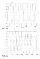
- FIGS. 3 a -3 c show a phase comparison for the currents d-q, in the conditions of application of the method subject of the invention.
- FIG. 4 is a block diagram of a system for the diagnosis of the offset of the resolver of an electric motor, arranged for applying the method subject of the invention.
- the rotational speed of the rotor is indicated by w
- the axis d is the axis of minimum reluctance
- the axis q is in phase quadrature with respect to the axis d.
- the reference system ABC is first of all convertible into a stationary reference system d-q (shown in the figure with apex s) in which the axes are located in a fixed reference, via the conversion matrix
- ⁇ i q i d ⁇ ⁇ cos ⁇ ( ⁇ ) - sin ⁇ ( ⁇ ) sin ⁇ ( ⁇ ) cos ⁇ ( ⁇ ) ⁇ ⁇ ⁇ i q s i d s ⁇
- the method for the diagnosis of the offset of the resolver of an electric motor that forms the subject of the present invention is carried out with the motor not in motion via the application of voltage pulses to the phases of the motor, having a sinusoidal waveform at a preset frequency, for example in the range between 400 Hz and 1.2 kHz, and preferably around 800 Hz, in such a manner as to determine the injection of pulses of an exploring excitation current on an axis of minimum reluctance of the system (axis d) and evaluating the effects that these have on the current that is established on the axis of minimum reluctance (axis d) and on the axis in quadrature to it (axis q).
- a preset frequency for example in the range between 400 Hz and 1.2 kHz, and preferably around 800 Hz
- the injection of the exploring current on the axis d of the system happens, without generating torque, by establishing voltages or injecting current onto the phases according to the aforementioned equations of the Park transforms.
- the current on the axis of minimum reluctance and on the axis in quadrature is determined by reading the currents on the phases of the motor and interpreted according to the aforementioned equations.
- the strategy for verifying the offset of the resolver comprises two phases.
- the injection of an exploring excitation current only on the axis d of the system corresponds to a current of maximum value, and proportional to the intensity of the injected exploring current, on this axis and to a current on the axis in quadrature theoretically zero.
- the exploring excitation current is injected into a non-correct reference system, but phase-shifted by an angle equal to the offset from the configuration of minimum reluctance.
- This offset corresponds to the error on the offset of the resolver, i.e. to a condition where the predetermined offset of the resolver does not correspond to the actual offset of the resolver.
- a current on the axis d is obtained with a value less than the preceding value, and a current on the axis q with a value higher than that obtained by applying the exploring excitation current to the motor in the configuration of minimum reluctance.
- FIGS. 3 a , 3 b , 3 c show the possible conditions in the case of a correct offset of the resolver.
- the current with which the motor responds to the application of the exploring excitation current is only on the axis d (curve D), with a negligible value of the current on the axis q (curve Q). It being desired to determine the response of the system in a different reference, in the case in which the reference system for application of the exploring excitation current is translated in excess of a predetermined and calibratable value with respect to the configuration of minimum reluctance, the currents d-q are in phase opposition to each other ( FIG.
- the above-described method of verification is implemented via a system generally represented in FIG. 4 .
- the electric motor is indicated by 10 , operationally controlled by a modulation module 12 of an inverter circuit, which receives at the input from a control module PI 14 voltage commands at each phase for the actuation of the motor, and from a block 16 for verification of the offset of the resolver, the control signals for an exploring current for each phase, indicated S A , S B , S C .
- These signals are produced from a current modulator 20 through a reference system transformation module 22 .
- the block 16 for verification of the offset of the resolver furthermore comprises a processing module 30 for diagnosing the position of the rotor to whose input a module for calculating the mean 32 is coupled, which is disposed downstream of a reference system transformation module 34 coupled to the output of the electric motor.
- the method is implemented by the system in the figure as follows.
- the method is carried out with the motor not in motion, whereby the commands for actuation of the motor, generated by the control module PI 14 , are temporarily inhibited or else the phase voltages for each phase are set to zero.
- a sinusoidal voltage waveform generated by the current modulator 20 is transformed from the rotating two-phase reference system d-q to the three-phase system A, B, C via the module 22 and supplied to the motor as a set of three control signals for an exploring excitation current for each phase, indicated S A , S B , S C , with an angle predetermined as a function of the phase of the strategy.
- the same offset angle of the resolver is used as is used in the normal operation of the vehicle.
- an angle is used whose value is varied with respect to the offset angle of the resolver by a predetermined and calibratable amount, preferably not greater than 20°, in such a manner as to evaluate the response of the motor in a different reference system.
- the diagnostic method of the present invention is thus executed in a first transient (following a first pulse of exploring excitation current) considering the position of the rotor read by the resolver, in a second transient (following a second pulse of exploring excitation current) considering the position of the rotor read by the resolver phase-shifted by a predetermined extra angle, in a third transient (following a third pulse of exploring excitation current) considering the position of the rotor read by the resolver phase-shifted by a reduced predetermined angle.
- the current measured on the windings of the electric motor is transformed from the three-phase reference system A, B, C to the rotating two-phase reference system d-q in the module 34 .
- a moving average is applied that is useful for obtaining a constant indicator that can be more easily analyzed for the transient in question, typically of 100 ms duration for each of the three measurement transients.
- the moving average is carried out via an average of the values that each current assumes within a preset period corresponding to the transient or to its own internal interval.
- This procedure evaluates which currents d-q the system applies with the position of the rotor used by the vehicle, and subsequently to assess whether this is the correct position (thus with minimum reluctance) by varying the reference system in which the exploring excitation current is applied.
- a second control is furthermore executed based on the phase of the currents d-q.
- the method subject of the invention is exclusively implemented when the motor is stationary, for example, in a currently preferred embodiment, before each start to movement of the electric motor, for example for a period of time of the order of 300 ms, which is imperceptible by a user, such as the driver of a vehicle equipped with the aforementioned electric motor.
- the method subject of the present invention may, conveniently, be implemented in any other similar condition of stationary or stopped vehicle for which there is zero torque demand, for example when the vehicle is parked or stopped at traffic lights.
- the method subject of the invention is carried out without imposing a movement on the rotor of the electric motor, whereby it may also be implemented in vehicles in which electric drive motors are applied directly to the wheels of the vehicle, without causing an undesirable movement of these.
Landscapes
- Engineering & Computer Science (AREA)
- Power Engineering (AREA)
- Transportation (AREA)
- Mechanical Engineering (AREA)
- Life Sciences & Earth Sciences (AREA)
- Sustainable Development (AREA)
- Sustainable Energy (AREA)
- General Physics & Mathematics (AREA)
- Physics & Mathematics (AREA)
- Microelectronics & Electronic Packaging (AREA)
- Transmission And Conversion Of Sensor Element Output (AREA)
- Control Of Motors That Do Not Use Commutators (AREA)
- Control Of Ac Motors In General (AREA)
Applications Claiming Priority (3)
| Application Number | Priority Date | Filing Date | Title |
|---|---|---|---|
| ITTO2014A0654 | 2014-08-11 | ||
| ITTO20140654 | 2014-08-11 | ||
| ITTO2014A000654 | 2014-08-11 |
Publications (2)
| Publication Number | Publication Date |
|---|---|
| US20160043614A1 US20160043614A1 (en) | 2016-02-11 |
| US9821679B2 true US9821679B2 (en) | 2017-11-21 |
Family
ID=51703329
Family Applications (1)
| Application Number | Title | Priority Date | Filing Date |
|---|---|---|---|
| US14/823,601 Active US9821679B2 (en) | 2014-08-11 | 2015-08-11 | Method for the diagnosis of the offset of the resolver of an electric machine |
Country Status (4)
| Country | Link |
|---|---|
| US (1) | US9821679B2 (enExample) |
| EP (1) | EP2985904B1 (enExample) |
| JP (1) | JP6404190B2 (enExample) |
| CN (1) | CN105375846B (enExample) |
Families Citing this family (9)
| Publication number | Priority date | Publication date | Assignee | Title |
|---|---|---|---|---|
| CN109639209A (zh) * | 2017-10-09 | 2019-04-16 | 郑州宇通客车股份有限公司 | 一种电动汽车电机电角度调节方法及其装置 |
| KR102383373B1 (ko) * | 2017-11-21 | 2022-04-05 | 현대자동차주식회사 | 친환경 차량의 레졸버 옵셋 보정 장치 및 방법 |
| CN109327173A (zh) * | 2018-11-14 | 2019-02-12 | 苏州绿控传动科技股份有限公司 | 一种永磁同步电机旋转变压器零位自动识别方法 |
| DE102019111146A1 (de) * | 2019-04-30 | 2020-11-05 | Valeo Siemens Eautomotive Germany Gmbh | Verfahren zum Bestimmen eines Offsets eines Winkellagegebers an einer Rotorwelle einer elektrischen Maschine |
| KR102219185B1 (ko) * | 2019-11-29 | 2021-02-23 | 주식회사 브이씨텍 | 전기 자동차 제어 유닛의 실시간 전류 옵셋 보정 방법 |
| KR102403505B1 (ko) * | 2020-01-31 | 2022-05-27 | 국민대학교산학협력단 | 무부하 환경에서 영구자석 동기 전동기의 회전자의 초기 위치를 검출하는 방법 및 장치 |
| CN115189613A (zh) * | 2021-04-07 | 2022-10-14 | 日本电产艾莱希斯株式会社 | 电动机装置及车辆 |
| CN113271043B (zh) * | 2021-05-26 | 2022-12-23 | 永大电梯设备(中国)有限公司 | 旋转变压器转子同永磁同步电机转子角度偏差校正方法 |
| DE102022110304A1 (de) * | 2022-04-28 | 2023-11-02 | Schaeffler Technologies AG & Co. KG | Verfahren zur Bestimmung einer initialen Rotorlage eines Rotors, Computerprogrammprodukt, Steuereinheit und elektrische Maschine |
Citations (9)
| Publication number | Priority date | Publication date | Assignee | Title |
|---|---|---|---|---|
| US20050104551A1 (en) * | 2003-02-28 | 2005-05-19 | Mitsubishi Denki Kabushiki Kaisha | Synchronous motor control device and method of correcting deviation in rotational position of synchronous motor |
| JP2005143256A (ja) * | 2003-11-10 | 2005-06-02 | Matsushita Electric Ind Co Ltd | モータ制御装置 |
| US20060290305A1 (en) * | 2005-06-27 | 2006-12-28 | Denso Corporation | Motor control apparatus |
| US20100171455A1 (en) | 2009-01-05 | 2010-07-08 | Gm Global Technology Operations, Inc. | Initial polarity detection for permanent magnet motor drives |
| EP2437391A1 (en) | 2009-05-27 | 2012-04-04 | Mitsubishi Electric Corporation | Device for estimating magnetic pole position in synchronous motor |
| US20130106325A1 (en) * | 2010-05-21 | 2013-05-02 | Michelin Recherche Et Technique S.A. | Equipment and method for measuring the offset angle of a resolver in a synchronous electric machine |
| US20130134914A1 (en) * | 2010-03-11 | 2013-05-30 | Trw Limited | Electric Motor Control |
| FR2990088A1 (fr) | 2012-04-30 | 2013-11-01 | Renault Sa | Procede de determination du decalage angulaire entre le rotor et le stator d'une machine electrique d'un vehicule automobile |
| US20140015457A1 (en) * | 2012-07-12 | 2014-01-16 | Kia Motors Corporation | System and method for calibrating offset of motor resolver |
Family Cites Families (9)
| Publication number | Priority date | Publication date | Assignee | Title |
|---|---|---|---|---|
| JP3675192B2 (ja) * | 1998-09-28 | 2005-07-27 | 株式会社日立製作所 | モータ制御装置および電気車用制御装置およびハイブリッド車用制御装置 |
| GB2428144B (en) * | 2004-01-07 | 2007-09-19 | Mitsubishi Electric Corp | Motor Controller |
| JP5055836B2 (ja) * | 2006-05-25 | 2012-10-24 | 日産自動車株式会社 | 同期モーター用磁極位置センサーの位相ズレ検出装置および検出方法 |
| DE102006025906A1 (de) * | 2006-06-02 | 2007-12-06 | Robert Bosch Gmbh | Verfahren zur Erkennung der Sensorzuordnung innerhalb einer elektrischen Maschine |
| FR2960357B1 (fr) * | 2010-05-21 | 2012-06-29 | Soc Tech Michelin | Procede de reglage automatique d'un resolveur d'une machine electrique |
| JP2010220472A (ja) * | 2010-05-31 | 2010-09-30 | Hitachi Automotive Systems Ltd | 同期モータ駆動装置 |
| JP5174205B2 (ja) * | 2011-04-01 | 2013-04-03 | ファナック株式会社 | 同期モータの磁極位置を検出する検出装置およびこれを備える制御装置 |
| CN103151982B (zh) * | 2011-12-07 | 2016-08-10 | 上海大郡动力控制技术有限公司 | 永磁电机旋转变压器检测零位补偿的自适应方法 |
| EP2888141B1 (en) * | 2012-08-21 | 2019-08-28 | Allison Transmission, Inc. | System and method for error correction in angular position sensors |
-
2015
- 2015-08-06 EP EP15179948.3A patent/EP2985904B1/en active Active
- 2015-08-10 JP JP2015158296A patent/JP6404190B2/ja active Active
- 2015-08-11 CN CN201510490912.6A patent/CN105375846B/zh active Active
- 2015-08-11 US US14/823,601 patent/US9821679B2/en active Active
Patent Citations (10)
| Publication number | Priority date | Publication date | Assignee | Title |
|---|---|---|---|---|
| US20050104551A1 (en) * | 2003-02-28 | 2005-05-19 | Mitsubishi Denki Kabushiki Kaisha | Synchronous motor control device and method of correcting deviation in rotational position of synchronous motor |
| JP2005143256A (ja) * | 2003-11-10 | 2005-06-02 | Matsushita Electric Ind Co Ltd | モータ制御装置 |
| US20060290305A1 (en) * | 2005-06-27 | 2006-12-28 | Denso Corporation | Motor control apparatus |
| US20100171455A1 (en) | 2009-01-05 | 2010-07-08 | Gm Global Technology Operations, Inc. | Initial polarity detection for permanent magnet motor drives |
| EP2437391A1 (en) | 2009-05-27 | 2012-04-04 | Mitsubishi Electric Corporation | Device for estimating magnetic pole position in synchronous motor |
| US20130134914A1 (en) * | 2010-03-11 | 2013-05-30 | Trw Limited | Electric Motor Control |
| US20130106325A1 (en) * | 2010-05-21 | 2013-05-02 | Michelin Recherche Et Technique S.A. | Equipment and method for measuring the offset angle of a resolver in a synchronous electric machine |
| FR2990088A1 (fr) | 2012-04-30 | 2013-11-01 | Renault Sa | Procede de determination du decalage angulaire entre le rotor et le stator d'une machine electrique d'un vehicule automobile |
| US20150134284A1 (en) | 2012-04-30 | 2015-05-14 | Renault S.A.S. | Method for determining the angular offset between the rotor and the stator of an electrical machine of a motor vehicle |
| US20140015457A1 (en) * | 2012-07-12 | 2014-01-16 | Kia Motors Corporation | System and method for calibrating offset of motor resolver |
Non-Patent Citations (1)
| Title |
|---|
| Search Report for Italian Patent Application No. TO20140654 dated Apr. 23, 2015. |
Also Published As
| Publication number | Publication date |
|---|---|
| CN105375846A (zh) | 2016-03-02 |
| US20160043614A1 (en) | 2016-02-11 |
| JP2016038390A (ja) | 2016-03-22 |
| EP2985904A1 (en) | 2016-02-17 |
| EP2985904B1 (en) | 2018-12-05 |
| CN105375846B (zh) | 2019-10-11 |
| JP6404190B2 (ja) | 2018-10-10 |
Similar Documents
| Publication | Publication Date | Title |
|---|---|---|
| US9821679B2 (en) | Method for the diagnosis of the offset of the resolver of an electric machine | |
| US9664499B2 (en) | Method for determining the angular offset between the rotor and the stator of an electrical machine of a motor vehicle | |
| EP2754998B1 (en) | Error frequency component acquisition device, angle of rotation acquisition device, motor control device, and angle of rotation acquisition method | |
| US8185342B2 (en) | Estimating rotor angular position and velocity and verifying accuracy of position sensor outputs | |
| EP2063339B1 (en) | Control method of electromotor | |
| US10992245B2 (en) | Position estimation of permanent magnet synchronous machines through vibration induced saliency | |
| EP1292008A1 (en) | Phase angle diagnotics for sinusoidal controlled electric machine | |
| JP5273451B2 (ja) | モータ制御装置 | |
| KR20150047536A (ko) | 각 위치 센서들에서의 에러 정정을 위한 시스템 및 방법 | |
| JP2009526511A (ja) | 同期機を駆動するための方法および装置 | |
| KR101876064B1 (ko) | 영구자석 모터의 착자 불량 진단 방법 | |
| JP5267843B2 (ja) | 電動パワーステアリング装置 | |
| US8922200B2 (en) | Method and device for determining a current angular position of a rotatable magnetic component in an electric drive | |
| US20150214871A1 (en) | Method and System for Determining Motor Shaft Position | |
| US20210293583A1 (en) | Method for checking the setting of an angular position sensor of a rotor for a vehicle | |
| US20050043873A1 (en) | Current limit for an electric machine | |
| US9441943B2 (en) | Method of determining the position and the speed of a rotor in a synchronous electric machine using state observers | |
| JP2013220007A (ja) | センサレスモータの制御方法、装置及び電動装置 | |
| WO2018110455A1 (ja) | 回転角度推定装置、電動機制御装置および回転角度推定方法 | |
| EP2822175A1 (en) | Motor control device and control method therefor | |
| JP2007261520A (ja) | 電動パワーステアリング装置 | |
| JP2009100544A (ja) | モータ制御装置 | |
| JP2009261102A (ja) | モータ制御装置 | |
| JP2008086076A (ja) | 永久磁石同期電動機の制御装置 | |
| JP2010048774A (ja) | 位置センサ |
Legal Events
| Date | Code | Title | Description |
|---|---|---|---|
| AS | Assignment |
Owner name: MAGNETI MARELLI S.P.A., ITALY Free format text: ASSIGNMENT OF ASSIGNORS INTEREST;ASSIGNORS:STEFANI, ANDREA;FOSSI, ALESSANDRO;BETRO', ROBERTO;AND OTHERS;REEL/FRAME:036887/0471 Effective date: 20150826 |
|
| STCF | Information on status: patent grant |
Free format text: PATENTED CASE |
|
| CC | Certificate of correction | ||
| MAFP | Maintenance fee payment |
Free format text: PAYMENT OF MAINTENANCE FEE, 4TH YEAR, LARGE ENTITY (ORIGINAL EVENT CODE: M1551); ENTITY STATUS OF PATENT OWNER: LARGE ENTITY Year of fee payment: 4 |
|
| FEPP | Fee payment procedure |
Free format text: MAINTENANCE FEE REMINDER MAILED (ORIGINAL EVENT CODE: REM.); ENTITY STATUS OF PATENT OWNER: LARGE ENTITY |