EP2985904A1 - Method for the diagnosis of the offset of the resolver of an electric machine - Google Patents
Method for the diagnosis of the offset of the resolver of an electric machine Download PDFInfo
- Publication number
- EP2985904A1 EP2985904A1 EP15179948.3A EP15179948A EP2985904A1 EP 2985904 A1 EP2985904 A1 EP 2985904A1 EP 15179948 A EP15179948 A EP 15179948A EP 2985904 A1 EP2985904 A1 EP 2985904A1
- Authority
- EP
- European Patent Office
- Prior art keywords
- axis
- resolver
- offset
- current
- minimum reluctance
- Prior art date
- Legal status (The legal status is an assumption and is not a legal conclusion. Google has not performed a legal analysis and makes no representation as to the accuracy of the status listed.)
- Granted
Links
- 238000000034 method Methods 0.000 title claims abstract description 32
- 238000003745 diagnosis Methods 0.000 title claims abstract description 9
- 230000005284 excitation Effects 0.000 claims abstract description 37
- 230000001052 transient effect Effects 0.000 claims abstract description 35
- 230000007547 defect Effects 0.000 claims abstract description 9
- 238000002347 injection Methods 0.000 claims abstract description 8
- 239000007924 injection Substances 0.000 claims abstract description 8
- 238000004804 winding Methods 0.000 description 11
- 230000009466 transformation Effects 0.000 description 8
- 238000012795 verification Methods 0.000 description 4
- 230000006399 behavior Effects 0.000 description 3
- 230000006870 function Effects 0.000 description 3
- 230000004048 modification Effects 0.000 description 3
- 238000012986 modification Methods 0.000 description 3
- 238000010586 diagram Methods 0.000 description 2
- 239000011159 matrix material Substances 0.000 description 2
- 230000004044 response Effects 0.000 description 2
- 230000001133 acceleration Effects 0.000 description 1
- 230000000903 blocking effect Effects 0.000 description 1
- 238000006243 chemical reaction Methods 0.000 description 1
- 230000001419 dependent effect Effects 0.000 description 1
- 238000002405 diagnostic procedure Methods 0.000 description 1
- 230000000694 effects Effects 0.000 description 1
- 238000005516 engineering process Methods 0.000 description 1
- 230000014509 gene expression Effects 0.000 description 1
- 238000005259 measurement Methods 0.000 description 1
- 230000010363 phase shift Effects 0.000 description 1
- 238000012545 processing Methods 0.000 description 1
- 239000000243 solution Substances 0.000 description 1
- 239000007858 starting material Substances 0.000 description 1
- 238000000844 transformation Methods 0.000 description 1
- 230000007704 transition Effects 0.000 description 1
Images


Classifications
-
- B—PERFORMING OPERATIONS; TRANSPORTING
- B60—VEHICLES IN GENERAL
- B60L—PROPULSION OF ELECTRICALLY-PROPELLED VEHICLES; SUPPLYING ELECTRIC POWER FOR AUXILIARY EQUIPMENT OF ELECTRICALLY-PROPELLED VEHICLES; ELECTRODYNAMIC BRAKE SYSTEMS FOR VEHICLES IN GENERAL; MAGNETIC SUSPENSION OR LEVITATION FOR VEHICLES; MONITORING OPERATING VARIABLES OF ELECTRICALLY-PROPELLED VEHICLES; ELECTRIC SAFETY DEVICES FOR ELECTRICALLY-PROPELLED VEHICLES
- B60L15/00—Methods, circuits, or devices for controlling the traction-motor speed of electrically-propelled vehicles
- B60L15/02—Methods, circuits, or devices for controlling the traction-motor speed of electrically-propelled vehicles characterised by the form of the current used in the control circuit
- B60L15/025—Methods, circuits, or devices for controlling the traction-motor speed of electrically-propelled vehicles characterised by the form of the current used in the control circuit using field orientation; Vector control; Direct Torque Control [DTC]
-
- B—PERFORMING OPERATIONS; TRANSPORTING
- B60—VEHICLES IN GENERAL
- B60L—PROPULSION OF ELECTRICALLY-PROPELLED VEHICLES; SUPPLYING ELECTRIC POWER FOR AUXILIARY EQUIPMENT OF ELECTRICALLY-PROPELLED VEHICLES; ELECTRODYNAMIC BRAKE SYSTEMS FOR VEHICLES IN GENERAL; MAGNETIC SUSPENSION OR LEVITATION FOR VEHICLES; MONITORING OPERATING VARIABLES OF ELECTRICALLY-PROPELLED VEHICLES; ELECTRIC SAFETY DEVICES FOR ELECTRICALLY-PROPELLED VEHICLES
- B60L3/00—Electric devices on electrically-propelled vehicles for safety purposes; Monitoring operating variables, e.g. speed, deceleration or energy consumption
- B60L3/0023—Detecting, eliminating, remedying or compensating for drive train abnormalities, e.g. failures within the drive train
- B60L3/0038—Detecting, eliminating, remedying or compensating for drive train abnormalities, e.g. failures within the drive train relating to sensors
-
- B—PERFORMING OPERATIONS; TRANSPORTING
- B60—VEHICLES IN GENERAL
- B60L—PROPULSION OF ELECTRICALLY-PROPELLED VEHICLES; SUPPLYING ELECTRIC POWER FOR AUXILIARY EQUIPMENT OF ELECTRICALLY-PROPELLED VEHICLES; ELECTRODYNAMIC BRAKE SYSTEMS FOR VEHICLES IN GENERAL; MAGNETIC SUSPENSION OR LEVITATION FOR VEHICLES; MONITORING OPERATING VARIABLES OF ELECTRICALLY-PROPELLED VEHICLES; ELECTRIC SAFETY DEVICES FOR ELECTRICALLY-PROPELLED VEHICLES
- B60L3/00—Electric devices on electrically-propelled vehicles for safety purposes; Monitoring operating variables, e.g. speed, deceleration or energy consumption
- B60L3/0023—Detecting, eliminating, remedying or compensating for drive train abnormalities, e.g. failures within the drive train
- B60L3/0061—Detecting, eliminating, remedying or compensating for drive train abnormalities, e.g. failures within the drive train relating to electrical machines
-
- B—PERFORMING OPERATIONS; TRANSPORTING
- B60—VEHICLES IN GENERAL
- B60L—PROPULSION OF ELECTRICALLY-PROPELLED VEHICLES; SUPPLYING ELECTRIC POWER FOR AUXILIARY EQUIPMENT OF ELECTRICALLY-PROPELLED VEHICLES; ELECTRODYNAMIC BRAKE SYSTEMS FOR VEHICLES IN GENERAL; MAGNETIC SUSPENSION OR LEVITATION FOR VEHICLES; MONITORING OPERATING VARIABLES OF ELECTRICALLY-PROPELLED VEHICLES; ELECTRIC SAFETY DEVICES FOR ELECTRICALLY-PROPELLED VEHICLES
- B60L3/00—Electric devices on electrically-propelled vehicles for safety purposes; Monitoring operating variables, e.g. speed, deceleration or energy consumption
- B60L3/12—Recording operating variables ; Monitoring of operating variables
-
- G—PHYSICS
- G01—MEASURING; TESTING
- G01D—MEASURING NOT SPECIALLY ADAPTED FOR A SPECIFIC VARIABLE; ARRANGEMENTS FOR MEASURING TWO OR MORE VARIABLES NOT COVERED IN A SINGLE OTHER SUBCLASS; TARIFF METERING APPARATUS; MEASURING OR TESTING NOT OTHERWISE PROVIDED FOR
- G01D5/00—Mechanical means for transferring the output of a sensing member; Means for converting the output of a sensing member to another variable where the form or nature of the sensing member does not constrain the means for converting; Transducers not specially adapted for a specific variable
- G01D5/12—Mechanical means for transferring the output of a sensing member; Means for converting the output of a sensing member to another variable where the form or nature of the sensing member does not constrain the means for converting; Transducers not specially adapted for a specific variable using electric or magnetic means
- G01D5/14—Mechanical means for transferring the output of a sensing member; Means for converting the output of a sensing member to another variable where the form or nature of the sensing member does not constrain the means for converting; Transducers not specially adapted for a specific variable using electric or magnetic means influencing the magnitude of a current or voltage
- G01D5/20—Mechanical means for transferring the output of a sensing member; Means for converting the output of a sensing member to another variable where the form or nature of the sensing member does not constrain the means for converting; Transducers not specially adapted for a specific variable using electric or magnetic means influencing the magnitude of a current or voltage by varying inductance, e.g. by a movable armature
- G01D5/204—Mechanical means for transferring the output of a sensing member; Means for converting the output of a sensing member to another variable where the form or nature of the sensing member does not constrain the means for converting; Transducers not specially adapted for a specific variable using electric or magnetic means influencing the magnitude of a current or voltage by varying inductance, e.g. by a movable armature by influencing the mutual induction between two or more coils
- G01D5/2073—Mechanical means for transferring the output of a sensing member; Means for converting the output of a sensing member to another variable where the form or nature of the sensing member does not constrain the means for converting; Transducers not specially adapted for a specific variable using electric or magnetic means influencing the magnitude of a current or voltage by varying inductance, e.g. by a movable armature by influencing the mutual induction between two or more coils by movement of a single coil with respect to two or more coils
-
- G—PHYSICS
- G01—MEASURING; TESTING
- G01D—MEASURING NOT SPECIALLY ADAPTED FOR A SPECIFIC VARIABLE; ARRANGEMENTS FOR MEASURING TWO OR MORE VARIABLES NOT COVERED IN A SINGLE OTHER SUBCLASS; TARIFF METERING APPARATUS; MEASURING OR TESTING NOT OTHERWISE PROVIDED FOR
- G01D5/00—Mechanical means for transferring the output of a sensing member; Means for converting the output of a sensing member to another variable where the form or nature of the sensing member does not constrain the means for converting; Transducers not specially adapted for a specific variable
- G01D5/12—Mechanical means for transferring the output of a sensing member; Means for converting the output of a sensing member to another variable where the form or nature of the sensing member does not constrain the means for converting; Transducers not specially adapted for a specific variable using electric or magnetic means
- G01D5/244—Mechanical means for transferring the output of a sensing member; Means for converting the output of a sensing member to another variable where the form or nature of the sensing member does not constrain the means for converting; Transducers not specially adapted for a specific variable using electric or magnetic means influencing characteristics of pulses or pulse trains; generating pulses or pulse trains
- G01D5/24471—Error correction
- G01D5/2448—Correction of gain, threshold, offset or phase control
-
- H—ELECTRICITY
- H02—GENERATION; CONVERSION OR DISTRIBUTION OF ELECTRIC POWER
- H02K—DYNAMO-ELECTRIC MACHINES
- H02K11/00—Structural association of dynamo-electric machines with electric components or with devices for shielding, monitoring or protection
- H02K11/20—Structural association of dynamo-electric machines with electric components or with devices for shielding, monitoring or protection for measuring, monitoring, testing, protecting or switching
- H02K11/21—Devices for sensing speed or position, or actuated thereby
- H02K11/225—Detecting coils
-
- H—ELECTRICITY
- H02—GENERATION; CONVERSION OR DISTRIBUTION OF ELECTRIC POWER
- H02P—CONTROL OR REGULATION OF ELECTRIC MOTORS, ELECTRIC GENERATORS OR DYNAMO-ELECTRIC CONVERTERS; CONTROLLING TRANSFORMERS, REACTORS OR CHOKE COILS
- H02P21/00—Arrangements or methods for the control of electric machines by vector control, e.g. by control of field orientation
- H02P21/24—Vector control not involving the use of rotor position or rotor speed sensors
- H02P21/32—Determining the initial rotor position
-
- H—ELECTRICITY
- H02—GENERATION; CONVERSION OR DISTRIBUTION OF ELECTRIC POWER
- H02P—CONTROL OR REGULATION OF ELECTRIC MOTORS, ELECTRIC GENERATORS OR DYNAMO-ELECTRIC CONVERTERS; CONTROLLING TRANSFORMERS, REACTORS OR CHOKE COILS
- H02P6/00—Arrangements for controlling synchronous motors or other dynamo-electric motors using electronic commutation dependent on the rotor position; Electronic commutators therefor
- H02P6/14—Electronic commutators
- H02P6/16—Circuit arrangements for detecting position
- H02P6/18—Circuit arrangements for detecting position without separate position detecting elements
- H02P6/183—Circuit arrangements for detecting position without separate position detecting elements using an injected high frequency signal
-
- B—PERFORMING OPERATIONS; TRANSPORTING
- B60—VEHICLES IN GENERAL
- B60L—PROPULSION OF ELECTRICALLY-PROPELLED VEHICLES; SUPPLYING ELECTRIC POWER FOR AUXILIARY EQUIPMENT OF ELECTRICALLY-PROPELLED VEHICLES; ELECTRODYNAMIC BRAKE SYSTEMS FOR VEHICLES IN GENERAL; MAGNETIC SUSPENSION OR LEVITATION FOR VEHICLES; MONITORING OPERATING VARIABLES OF ELECTRICALLY-PROPELLED VEHICLES; ELECTRIC SAFETY DEVICES FOR ELECTRICALLY-PROPELLED VEHICLES
- B60L2220/00—Electrical machine types; Structures or applications thereof
- B60L2220/10—Electrical machine types
- B60L2220/14—Synchronous machines
-
- B—PERFORMING OPERATIONS; TRANSPORTING
- B60—VEHICLES IN GENERAL
- B60L—PROPULSION OF ELECTRICALLY-PROPELLED VEHICLES; SUPPLYING ELECTRIC POWER FOR AUXILIARY EQUIPMENT OF ELECTRICALLY-PROPELLED VEHICLES; ELECTRODYNAMIC BRAKE SYSTEMS FOR VEHICLES IN GENERAL; MAGNETIC SUSPENSION OR LEVITATION FOR VEHICLES; MONITORING OPERATING VARIABLES OF ELECTRICALLY-PROPELLED VEHICLES; ELECTRIC SAFETY DEVICES FOR ELECTRICALLY-PROPELLED VEHICLES
- B60L2220/00—Electrical machine types; Structures or applications thereof
- B60L2220/10—Electrical machine types
- B60L2220/16—DC brushless machines
-
- B—PERFORMING OPERATIONS; TRANSPORTING
- B60—VEHICLES IN GENERAL
- B60L—PROPULSION OF ELECTRICALLY-PROPELLED VEHICLES; SUPPLYING ELECTRIC POWER FOR AUXILIARY EQUIPMENT OF ELECTRICALLY-PROPELLED VEHICLES; ELECTRODYNAMIC BRAKE SYSTEMS FOR VEHICLES IN GENERAL; MAGNETIC SUSPENSION OR LEVITATION FOR VEHICLES; MONITORING OPERATING VARIABLES OF ELECTRICALLY-PROPELLED VEHICLES; ELECTRIC SAFETY DEVICES FOR ELECTRICALLY-PROPELLED VEHICLES
- B60L2240/00—Control parameters of input or output; Target parameters
- B60L2240/40—Drive Train control parameters
- B60L2240/42—Drive Train control parameters related to electric machines
- B60L2240/421—Speed
-
- B—PERFORMING OPERATIONS; TRANSPORTING
- B60—VEHICLES IN GENERAL
- B60L—PROPULSION OF ELECTRICALLY-PROPELLED VEHICLES; SUPPLYING ELECTRIC POWER FOR AUXILIARY EQUIPMENT OF ELECTRICALLY-PROPELLED VEHICLES; ELECTRODYNAMIC BRAKE SYSTEMS FOR VEHICLES IN GENERAL; MAGNETIC SUSPENSION OR LEVITATION FOR VEHICLES; MONITORING OPERATING VARIABLES OF ELECTRICALLY-PROPELLED VEHICLES; ELECTRIC SAFETY DEVICES FOR ELECTRICALLY-PROPELLED VEHICLES
- B60L2240/00—Control parameters of input or output; Target parameters
- B60L2240/40—Drive Train control parameters
- B60L2240/42—Drive Train control parameters related to electric machines
- B60L2240/427—Voltage
-
- B—PERFORMING OPERATIONS; TRANSPORTING
- B60—VEHICLES IN GENERAL
- B60L—PROPULSION OF ELECTRICALLY-PROPELLED VEHICLES; SUPPLYING ELECTRIC POWER FOR AUXILIARY EQUIPMENT OF ELECTRICALLY-PROPELLED VEHICLES; ELECTRODYNAMIC BRAKE SYSTEMS FOR VEHICLES IN GENERAL; MAGNETIC SUSPENSION OR LEVITATION FOR VEHICLES; MONITORING OPERATING VARIABLES OF ELECTRICALLY-PROPELLED VEHICLES; ELECTRIC SAFETY DEVICES FOR ELECTRICALLY-PROPELLED VEHICLES
- B60L2240/00—Control parameters of input or output; Target parameters
- B60L2240/40—Drive Train control parameters
- B60L2240/42—Drive Train control parameters related to electric machines
- B60L2240/429—Current
-
- H—ELECTRICITY
- H02—GENERATION; CONVERSION OR DISTRIBUTION OF ELECTRIC POWER
- H02P—CONTROL OR REGULATION OF ELECTRIC MOTORS, ELECTRIC GENERATORS OR DYNAMO-ELECTRIC CONVERTERS; CONTROLLING TRANSFORMERS, REACTORS OR CHOKE COILS
- H02P2203/00—Indexing scheme relating to controlling arrangements characterised by the means for detecting the position of the rotor
- H02P2203/11—Determination or estimation of the rotor position or other motor parameters based on the analysis of high frequency signals
-
- Y—GENERAL TAGGING OF NEW TECHNOLOGICAL DEVELOPMENTS; GENERAL TAGGING OF CROSS-SECTIONAL TECHNOLOGIES SPANNING OVER SEVERAL SECTIONS OF THE IPC; TECHNICAL SUBJECTS COVERED BY FORMER USPC CROSS-REFERENCE ART COLLECTIONS [XRACs] AND DIGESTS
- Y02—TECHNOLOGIES OR APPLICATIONS FOR MITIGATION OR ADAPTATION AGAINST CLIMATE CHANGE
- Y02T—CLIMATE CHANGE MITIGATION TECHNOLOGIES RELATED TO TRANSPORTATION
- Y02T10/00—Road transport of goods or passengers
- Y02T10/60—Other road transportation technologies with climate change mitigation effect
- Y02T10/64—Electric machine technologies in electromobility
Definitions
- the present invention relates in general to electric machines and, in particular, to a diagnostic methodology for the recognition of the mutual positioning of a rotor and a stator in an electric machine, specifically an electric motor without brushes (brushless) with internal magnets, such as for example a drive motor for a vehicle.
- the invention relates to a method for the diagnosis of the offset of the resolver of an electric machine according to the preamble of Claim 1.
- An electric machine such as an electric starter motor or a drive motor for an electric or hybrid vehicle, is conventionally equipped with a device for sensing the angular position or resolver, adapted to determine the mutual angular position between a rotary shaft and a stationary portion of the machine, which corresponds to the mutual angular position between a rotor and a stator.
- the information on angular position between rotor and stator is indispensible in the control of an electric motor, so that a unit for controlling the motor including an inverter circuit for generating the excitation currents of the motor is able to control the injection of current into the motor in the correct manner, controlling the rotation of the motor in the desired direction.
- the resolver is an analogue transducer of angular position, which comprises a mobile part, associated with the rotor or with the rotary shaft of the electric machine, and a fixed part, associated with the stator or with another stationary portion of the electric machine.
- the resolver comprises an excitation winding through which a sinusoidal excitation current flows (with an angular frequency ⁇ higher than the angular velocity), and two stationary windings (rigidly attached to the fixed part) in electrical phase quadrature.
- the excitation winding may be rigidly attached to the mobile part, or this may also be accommodated on the fixed part, if the mobile part has at least one pair of magnetic poles.
- the mobile part set in rotation induces in the fixed windings an e.m.f. composed of two components: a first component of transformer-type origin, due to the variations in an excitation voltage V r , and a second component due to the relative motion of the mobile part with respect to the fixed windings, which is proportional to the sine or to the cosine of the angle ⁇ identified by the position of the mobile part with respect to a predetermined reference.
- the sine and the cosine of the angular position of the mobile part modulate in amplitude the carrier with an angular frequency ⁇ present on the winding excitation. From the voltage signals V s1 and V s2 at ends of the fixed windings, by demodulation, it is possible to obtain an estimate of the angle ⁇ .
- the mobile part and the fixed part of the resolver are stably attached to the motor in a random, undetermined position or - as an alternative, if a controlled procedure for assembly of the resolver with respect to the stator of the motor is provided - in a position close to a nominal value, taking into account the assembly tolerances, whereby a difference is established between the reference position of the resolver and a reference position of minimum reluctance of the electric motor, commonly known as offset of the resolver.
- This position is measured at the end of the assembly line of an electric motor and is stored in memory within the control unit of the motor as the predetermined offset of the resolver.
- a method for calibrating the offset of the resolver is known from US 2014/015457 .
- control unit In normal operation of the electric motor, the control unit is capable of determining the correct angular position of the motor (the mutual angular position between stator and rotor) based on the output signal of the resolver knowing the offset of the resolver.
- anomalies During the normal operation of an electric motor, it is possible for anomalies to occur, for example on the rotor, in such a manner as to modify the offset of the resolver with respect to the predetermined one imposed at the production site.
- control unit of the motor does not recognize a modification of the offset of the resolver, the latter is no longer capable of determining the correct angular position of the motor or the position of minimum reluctance of the motor, which causes a lower torque to be provided or creates even serious drawbacks, such as unexpected behaviours in acceleration and deceleration when the vehicle is being driven, and - as a result of the erroneous control of the motor - the rupture of the rotor which determines the blocking of the motor drive shaft or the rupture of the pinion.
- the erroneous interpretation of the position of the rotor by the control unit may cause the inversion of the sign of the torque applied to the drive shaft with respect to that requested, causing the movement of the vehicle in the opposite direction to that desired, with consequent serious risks for the people on board the vehicle or around it.
- the aim of the present invention is thus to provide a satisfactory solution to the aforementioned problems, while avoiding the drawbacks of the known technology.
- the aim of the present invention is to provide a method that may be implemented on board an electric motor for recognizing a modification of the offset of the resolver, for example a modification of the offset of the resolver caused accidentally, i.e. for recognizing if the actual offset of the resolver corresponds to the predetermined offset of the resolver.
- a further subject of the invention is a system for the diagnosis of the offset of the resolver of an electric machine, arranged for implementing the method of the invention.
- the present invention is based on the principle of diagnosing the offset of the resolver of an electric machine, known a priori since determined at the production site, with the purpose of determining the correctness of information on angular position of the electric machine, i.e. of verifying the validity of the predetermined offset of the resolver, i.e. the correspondence between the predetermined offset of the resolver and the actual offset of the resolver.
- Diagnosis of the offset of the resolver of an electric machine means verification of the correct phasing between an angular position of the resolver and the mutual angular position between rotor and stator of the electric machine.
- the correctness of the assumed offset i.e. the correspondence of the actual offset of the resolver with the predetermined offset of the resolver, is verified by exciting the motor in pulsed mode in a preset configuration of assumed minimum reluctance determined as a function of the offset of the resolver known a priori, and in preset positions angularly displaced with respect to the position of assumed minimum reluctance by a calibratable value.
- the position of minimum reluctance of an electric machine is a known position (acquired from the resolver having a knowledge of the predetermined offset of the resolver) obtained from the phase-shift between the magnetic axis of the stator phases (typically that associated with the phase a) and the rotor axis coinciding with the magnetic path that more is opposed to the magnetic field lines.
- the configuration of minimum reluctance is a configuration for which voltages applied to the phases of an electric machine exclusively determine the excitation of a current on an axis aligned to a phase of the machine, whereby an electromagnetic drive torque is not generated.
- the method for the diagnosis of the offset of the resolver of an electric motor that forms the subject of the present invention is carried out with the motor not in motion via the application of voltage pulses to the phases of the motor, having a sinusoidal waveform at a preset frequency, for example in the range between 400Hz and 1.2kHz, and preferably around 800Hz, in such a manner as to determine the injection of pulses of an exploring excitation current on an axis of minimum reluctance of the system (axis d) and evaluating the effects that these have on the current that is established on the axis of minimum reluctance (axis d) and on the axis in quadrature to it (axis q).
- a preset frequency for example in the range between 400Hz and 1.2kHz, and preferably around 800Hz
- the injection of the exploring current on the axis d of the system happens, without generating torque, by establishing voltages or injecting current onto the phases according to the aforementioned equations of the Park transforms.
- the current on the axis of minimum reluctance and on the axis in quadrature is determined by reading the currents on the phases of the motor and interpreted according to the aforementioned equations.
- the strategy for verifying the offset of the resolver comprises two phases.
- the injection of an exploring excitation current only on the axis d of the system corresponds to a current of maximum value, and proportional to the intensity of the injected exploring current, on this axis and to a current on the axis in quadrature theoretically zero.
- the exploring excitation current is injected into a non-correct reference system, but phase-shifted by an angle equal to the offset from the configuration of minimum reluctance.
- This offset corresponds to the errore on the offset of the resolver, i.e. to a condition where the predetermined offset of the resolver does not correspond to the actual offset of the resolver.
- a current on the axis d is obtained with a value less than the preceding value, and a current on the axis q with a value higher than that obtained by applying the exploring excitation current to the motor in the configuration of minimum reluctance.
- One further piece of information on the correctness of the offset of the resolver may be obtained by evaluating the phase of the currents d-q.
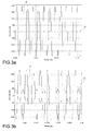
- Figures 3a, 3b , 3c show the possible conditions in the case of a correct offset of the resolver.
- the currents d-q are in phase opposition to each other ( figure 3b ), while in the case in which the reference system for application of the exploring excitation current is translated short of a value predetermined and calibratable with respect to the position of minimum reluctance, the currents d-q are in phase ( figure 3c ).
- the electric motor is indicated by 10, operationally controlled by a modulation module 12 of an inverter circuit, which receives at the input from a control module PI 14 voltage commands at each phase for the actuation of the motor, and from a block 16 for verification of the offset of the resolver, the control signals for an exploring current for each phase, indicated S A , S B , S C .
- These signals are produced from a current modulator 20 through a reference system transformation module 22.
- the block 16 for verification of the offset of the resolver furthermore comprises a processing module 30 for diagnosing the position of the rotor to whose input a module for calculating the mean 32 is coupled, which is disposed downstream of a reference system transformation module 34 coupled to the output of the electric motor.
- the method is implemented by the system in the figure as follows.
- the method is carried out with the motor not in motion, whereby the commands for actuation of the motor, generated by the control module PI 14, are temporarily inhibited or else the phase voltages for each phase are set to zero.
- a sinusoidal voltage waveform generated by the current modulator 20 is transformed from the rotating two-phase reference system d-q to the three-phase system A,B,C via the module 22 and supplied to the motor as a set of three control signals for an exploring excitation current for each phase, indicated S A , S B , S C , with an angle predetermined as a function of the phase of the strategy.
- the same offset angle of the resolver is used as is used in the normal operation of the vehicle.
- an angle is used whose value is varied with respect to the offset angle of the resolver by a predetermined and calibratable amount, preferably not greater than 20°, in such a manner as to evaluate the response of the motor in a different reference system.
- the diagnostic method subject of the invention is thus executed in a first transient (following a first pulse of exploring excitation current) considering the position of the rotor read by the resolver, in a second transient (following a second pulse of exploring excitation current) considering the position of the rotor read by the resolver phase-shifted by a predetermined extra angle, in a third transient (following a third pulse of exploring excitation current) considering the position of the rotor read by the resolver phase-shifted by a reduced predetermined angle.
- the current measured on the windings of the electric machine is transformed from the three-phase reference system A,B,C to the rotating two-phase reference system d-q in the module 34.
- a moving average is applied that is useful for obtaining a constant indicator that can be more easily analyzed for the transient in question, typically of 100ms duration for each of the three measurement transients.
- the moving average is carried out via an average of the values that each current assumes within a preset period corresponding to the transient or to its own internal interval.
- This procedure allows to evaluate which currents d-q the system applies with the position of the rotor used by the vehicle, and subsequently to assess whether this is the correct position (thus with minimum reluctance) by varying the reference system in which the exploring excitation current is applied.
- a second control is furthermore executed based on the phase of the currents d-q.
- the method subject of the invention is exclusively implemented when the motor is stationary, for example, in a currently preferred embodiment, before each start to movement of the electric motor, for example for a period of time of the order of 300ms, which is imperceptible by a user, such as the driver of a vehicle equipped with the aforementioned electric motor.
- the method subject of the present invention may, conveniently, be implemented in any other similar condition of stationary or stopped vehicle for which there is zero torque demand, for example when the vehicle is parked or stopped at traffic lights.
- the method subject of the invention is carried out without imposing a movement on the rotor of the electric machine, whereby it may also be implemented in vehicles in which electric drive motors are applied directly to the wheels of the vehicle, without causing an undesirable movement of these.
Landscapes
- Engineering & Computer Science (AREA)
- Power Engineering (AREA)
- Transportation (AREA)
- Mechanical Engineering (AREA)
- Sustainable Energy (AREA)
- Life Sciences & Earth Sciences (AREA)
- Sustainable Development (AREA)
- General Physics & Mathematics (AREA)
- Physics & Mathematics (AREA)
- Microelectronics & Electronic Packaging (AREA)
- Transmission And Conversion Of Sensor Element Output (AREA)
- Control Of Motors That Do Not Use Commutators (AREA)
- Control Of Ac Motors In General (AREA)
Abstract
Description
- The present invention relates in general to electric machines and, in particular, to a diagnostic methodology for the recognition of the mutual positioning of a rotor and a stator in an electric machine, specifically an electric motor without brushes (brushless) with internal magnets, such as for example a drive motor for a vehicle.
- More specifically, the invention relates to a method for the diagnosis of the offset of the resolver of an electric machine according to the preamble of Claim 1.
- An electric machine, such as an electric starter motor or a drive motor for an electric or hybrid vehicle, is conventionally equipped with a device for sensing the angular position or resolver, adapted to determine the mutual angular position between a rotary shaft and a stationary portion of the machine, which corresponds to the mutual angular position between a rotor and a stator.
- The information on angular position between rotor and stator is indispensible in the control of an electric motor, so that a unit for controlling the motor including an inverter circuit for generating the excitation currents of the motor is able to control the injection of current into the motor in the correct manner, controlling the rotation of the motor in the desired direction.
- The resolver is an analogue transducer of angular position, which comprises a mobile part, associated with the rotor or with the rotary shaft of the electric machine, and a fixed part, associated with the stator or with another stationary portion of the electric machine. The resolver comprises an excitation winding through which a sinusoidal excitation current flows (with an angular frequency ω higher than the angular velocity), and two stationary windings (rigidly attached to the fixed part) in electrical phase quadrature. The excitation winding may be rigidly attached to the mobile part, or this may also be accommodated on the fixed part, if the mobile part has at least one pair of magnetic poles.
- The principle of operation of the resolver is as follows: the mobile part set in rotation induces in the fixed windings an e.m.f. composed of two components: a first component of transformer-type origin, due to the variations in an excitation voltage Vr, and a second component due to the relative motion of the mobile part with respect to the fixed windings, which is proportional to the sine or to the cosine of the angle θ identified by the position of the mobile part with respect to a predetermined reference. Choosing θ = 0 when the excitation winding or a particular magnetic pole of the mobile part is aligned with one of the two fixed windings, the expressions for the voltage signals Vs1 and Vs2 at the ends of the fixed windings are respectively:


- The sine and the cosine of the angular position of the mobile part modulate in amplitude the carrier with an angular frequency ω present on the winding excitation. From the voltage signals Vs1 and Vs2 at ends of the fixed windings, by demodulation, it is possible to obtain an estimate of the angle θ.
- In the production line of an electric motor, the mobile part and the fixed part of the resolver are stably attached to the motor in a random, undetermined position or - as an alternative, if a controlled procedure for assembly of the resolver with respect to the stator of the motor is provided - in a position close to a nominal value, taking into account the assembly tolerances, whereby a difference is established between the reference position of the resolver and a reference position of minimum reluctance of the electric motor, commonly known as offset of the resolver.
- This position is measured at the end of the assembly line of an electric motor and is stored in memory within the control unit of the motor as the predetermined offset of the resolver.
- A method for calibrating the offset of the resolver is known from
US 2014/015457 . - In normal operation of the electric motor, the control unit is capable of determining the correct angular position of the motor (the mutual angular position between stator and rotor) based on the output signal of the resolver knowing the offset of the resolver.
- During the normal operation of an electric motor, it is possible for anomalies to occur, for example on the rotor, in such a manner as to modify the offset of the resolver with respect to the predetermined one imposed at the production site.
- If the control unit of the motor does not recognize a modification of the offset of the resolver, the latter is no longer capable of determining the correct angular position of the motor or the position of minimum reluctance of the motor, which causes a lower torque to be provided or creates even serious drawbacks, such as unexpected behaviours in acceleration and deceleration when the vehicle is being driven, and - as a result of the erroneous control of the motor - the rupture of the rotor which determines the blocking of the motor drive shaft or the rupture of the pinion.
- Equally disadvantageously, in the case of use of the electric motor in the start phase for the drive, the erroneous interpretation of the position of the rotor by the control unit may cause the inversion of the sign of the torque applied to the drive shaft with respect to that requested, causing the movement of the vehicle in the opposite direction to that desired, with consequent serious risks for the people on board the vehicle or around it.
- The aim of the present invention is thus to provide a satisfactory solution to the aforementioned problems, while avoiding the drawbacks of the known technology.
- In particular, the aim of the present invention is to provide a method that may be implemented on board an electric motor for recognizing a modification of the offset of the resolver, for example a modification of the offset of the resolver caused accidentally, i.e. for recognizing if the actual offset of the resolver corresponds to the predetermined offset of the resolver.
- According to the present invention such an aim is achieved by means of a method for diagnosis of the offset of the resolver of an electric machine having the features claimed in Claim 1.
- Particular embodiments form the subject of the dependent claims, whose content is intended to form an integral part of the present description.
- A further subject of the invention is a system for the diagnosis of the offset of the resolver of an electric machine, arranged for implementing the method of the invention.
- In summary, the present invention is based on the principle of diagnosing the offset of the resolver of an electric machine, known a priori since determined at the production site, with the purpose of determining the correctness of information on angular position of the electric machine, i.e. of verifying the validity of the predetermined offset of the resolver, i.e. the correspondence between the predetermined offset of the resolver and the actual offset of the resolver.
- Diagnosis of the offset of the resolver of an electric machine means verification of the correct phasing between an angular position of the resolver and the mutual angular position between rotor and stator of the electric machine.
- The correctness of the assumed offset, i.e. the correspondence of the actual offset of the resolver with the predetermined offset of the resolver, is verified by exciting the motor in pulsed mode in a preset configuration of assumed minimum reluctance determined as a function of the offset of the resolver known a priori, and in preset positions angularly displaced with respect to the position of assumed minimum reluctance by a calibratable value. The position of minimum reluctance of an electric machine is a known position (acquired from the resolver having a knowledge of the predetermined offset of the resolver) obtained from the phase-shift between the magnetic axis of the stator phases (typically that associated with the phase a) and the rotor axis coinciding with the magnetic path that more is opposed to the magnetic field lines. In other words, the configuration of minimum reluctance is a configuration for which voltages applied to the phases of an electric machine exclusively determine the excitation of a current on an axis aligned to a phase of the machine, whereby an electromagnetic drive torque is not generated.
- Further features and advantages of the invention will be presented in more detail in the following detailed description of one embodiment, given by way of non-limiting example, with reference to the appended drawings, in which:
-
Figure 1 is a representative diagram of the transformation from a three-phase reference system (ABC) to a rotating two-phase reference system (d-q) of the currents in an electric motor; -
Figure 2 shows the evolution of the currents d-q in the conditions of application of the method subject of the invention; -
Figures 3a-3c show a phase comparison for the currents d-q, in the conditions of application of the method subject of the invention; and -
Figure 4 is a block diagram of a system for the diagnosis of the offset of the resolver of an electric machine, arranged for applying the method subject of the invention. - For a correct understanding of the method subject of the invention, in the following by way of introduction, the mathematical theory is presented of direct and inverse transformation of the reference system ("Park transforms"), from a three-phase reference system (phases A, B, C of an electric motor) to a rotating two-phase reference system (d-q), which rotates aligned to the rotor of an electric motor, and vice versa.
- In
Figure 1 the rotational speed of the rotor is indicated by ω, the axis d is the axis of minimum reluctance and the axis q is in phase quadrature with respect to the axis d. - Considering a transformation of the currents (but the same transforms are also applicable to the voltages), the reference system ABC is first of all convertible into a stationary reference system d-q (shown in the figure with apex s) in which the axes are located in a fixed reference, via the conversion matrix

(where the current ic = - ia - ib) - From a stationary two-phase reference system, the following matrix allows the transition from the currents ds-qs to the currents d-q in a rotating reference system d-q:

- The transformations to be applied in order to obtain the inverse transformation from the rotating reference system d-q to the three-phase one ABC are implemented by applying the following matrices:


- The method for the diagnosis of the offset of the resolver of an electric motor that forms the subject of the present invention is carried out with the motor not in motion via the application of voltage pulses to the phases of the motor, having a sinusoidal waveform at a preset frequency, for example in the range between 400Hz and 1.2kHz, and preferably around 800Hz, in such a manner as to determine the injection of pulses of an exploring excitation current on an axis of minimum reluctance of the system (axis d) and evaluating the effects that these have on the current that is established on the axis of minimum reluctance (axis d) and on the axis in quadrature to it (axis q).
- In the motor, the injection of the exploring current on the axis d of the system happens, without generating torque, by establishing voltages or injecting current onto the phases according to the aforementioned equations of the Park transforms. In an analogous manner, the current on the axis of minimum reluctance and on the axis in quadrature is determined by reading the currents on the phases of the motor and interpreted according to the aforementioned equations.
- The strategy for verifying the offset of the resolver comprises two phases.
- In a motor, assuming a configuration of minimum reluctance, the injection of an exploring excitation current only on the axis d of the system corresponds to a current of maximum value, and proportional to the intensity of the injected exploring current, on this axis and to a current on the axis in quadrature theoretically zero.
- In the case in which a configuration of minimum reluctance is not verified, the exploring excitation current is injected into a non-correct reference system, but phase-shifted by an angle equal to the offset from the configuration of minimum reluctance. This offset corresponds to the errore on the offset of the resolver, i.e. to a condition where the predetermined offset of the resolver does not correspond to the actual offset of the resolver.
- By applying the same exploring excitation current on the axis d in the non-correct reference a current on the axis d is obtained with a value less than the preceding value, and a current on the axis q with a value higher than that obtained by applying the exploring excitation current to the motor in the configuration of minimum reluctance.
- These conditions are shown in
figure 2 , respectively highlighted in the areas indicated with the references A and B. - One further piece of information on the correctness of the offset of the resolver may be obtained by evaluating the phase of the currents d-q.
- Injecting an exploring excitation current into two reference systems translated by a preset and calibratable value, respectively in excess and in defect around the assumed configuration of minimum reluctance, known as a function of the offset of the resolver, it is possible to measure, for both the reference systems, the sign and the amplitude of the values result resulting from the current on the axis d and on the axis q via the formula:

-
Figures 3a, 3b ,3c show the possible conditions in the case of a correct offset of the resolver. - In
figure 3a , it may be noted that, in the configuration of minimum reluctance, the current with which the motor responds to the application of the exploring excitation current is only on the axis d (curve D), with a negligible value of the current on the axis q (curve Q). It being desired to determine the response of the system in a different reference, in the case in which the reference system for application of the exploring excitation current is translated in excess of a predetermined and calibratable value with respect to the configuration of minimum reluctance, the currents d-q are in phase opposition to each other (figure 3b ), while in the case in which the reference system for application of the exploring excitation current is translated short of a value predetermined and calibratable with respect to the position of minimum reluctance, the currents d-q are in phase (figure 3c ). - From the preceding discussion, it is understood that - in the case in which the two resulting terms have opposite signs - the offset of the resolver, via which the angular position of the motor is determined, is definitely correct. In the case in which the two terms on the other hand have the same signs, the offset of the resolver, via which the angular position of the motor is determined, is not correct.
- The above-described method of verification is implemented via a system generally represented in
figure 4 . - The electric motor is indicated by 10, operationally controlled by a
modulation module 12 of an inverter circuit, which receives at the input from acontrol module PI 14 voltage commands at each phase for the actuation of the motor, and from ablock 16 for verification of the offset of the resolver, the control signals for an exploring current for each phase, indicated SA, SB, SC. These signals are produced from acurrent modulator 20 through a referencesystem transformation module 22. - The
block 16 for verification of the offset of the resolver furthermore comprises aprocessing module 30 for diagnosing the position of the rotor to whose input a module for calculating themean 32 is coupled, which is disposed downstream of a referencesystem transformation module 34 coupled to the output of the electric motor. - The method is implemented by the system in the figure as follows.
- The method is carried out with the motor not in motion, whereby the commands for actuation of the motor, generated by the
control module PI 14, are temporarily inhibited or else the phase voltages for each phase are set to zero. - A sinusoidal voltage waveform generated by the
current modulator 20 is transformed from the rotating two-phase reference system d-q to the three-phase system A,B,C via themodule 22 and supplied to the motor as a set of three control signals for an exploring excitation current for each phase, indicated SA, SB, SC, with an angle predetermined as a function of the phase of the strategy. In a first phase, the same offset angle of the resolver is used as is used in the normal operation of the vehicle. In a second phase, an angle is used whose value is varied with respect to the offset angle of the resolver by a predetermined and calibratable amount, preferably not greater than 20°, in such a manner as to evaluate the response of the motor in a different reference system. - The diagnostic method subject of the invention is thus executed in a first transient (following a first pulse of exploring excitation current) considering the position of the rotor read by the resolver, in a second transient (following a second pulse of exploring excitation current) considering the position of the rotor read by the resolver phase-shifted by a predetermined extra angle, in a third transient (following a third pulse of exploring excitation current) considering the position of the rotor read by the resolver phase-shifted by a reduced predetermined angle.
- The current measured on the windings of the electric machine is transformed from the three-phase reference system A,B,C to the rotating two-phase reference system d-q in the
module 34. - Advantageously, to the value of the currents d-q obtained from the transformation from the three-phase system to the rotating two-phase system a moving average is applied that is useful for obtaining a constant indicator that can be more easily analyzed for the transient in question, typically of 100ms duration for each of the three measurement transients. The moving average is carried out via an average of the values that each current assumes within a preset period corresponding to the transient or to its own internal interval.
- This procedure allows to evaluate which currents d-q the system applies with the position of the rotor used by the vehicle, and subsequently to assess whether this is the correct position (thus with minimum reluctance) by varying the reference system in which the exploring excitation current is applied.
- In the case in which the assumed configuration of minimum reluctance is correct (the offset of the known resolver is correct) during the first transient a current of axis d higher and a current of axis q lower than that obtained in the other transients is obtained.
- In the case of an error in the assumed configuration of minimum reluctance, due to an error in the knowledge of the offset of the resolver, when the reference is displaced from the one that has been read, a current of axis d lower and a current of axis q higher than that evaluated in the first transient is always obtained.
- According to the method, a second control is furthermore executed based on the phase of the currents d-q.
- If the assumed configuration of minimum reluctance is correct (the offset of the known resolver is correct) two currents d-q will be obtained whose phase relationship is the following: in phase opposition, if the position is shifted in excess with respect to the one read (second transient, see
figure 3b ), and in phase, if the position is shifted in defect (third transient, seefigure 3c ). - In the case in which the assumed configuration of minimum reluctance is not correct (because of an error in the knowledge of the offset of the resolver), both in the second transient and in the third transient, the same phasing of the currents d-q will be obtained. In this case, both for a shift in excess and for a shift in defect, the behaviour in
figure 3b will be obtained if the position of the rotor read by the resolver exceeds that of minimum reluctance, whereas if the position of the rotor read by the resolver is not correct and in defect with respect to that of minimum reluctance, both for a shift in excess and for a shift in defect, the behaviour infigure 3c will be obtained. - The method subject of the invention is exclusively implemented when the motor is stationary, for example, in a currently preferred embodiment, before each start to movement of the electric motor, for example for a period of time of the order of 300ms, which is imperceptible by a user, such as the driver of a vehicle equipped with the aforementioned electric motor. The method subject of the present invention may, conveniently, be implemented in any other similar condition of stationary or stopped vehicle for which there is zero torque demand, for example when the vehicle is parked or stopped at traffic lights.
- As will become clearly apparent, the method subject of the invention is carried out without imposing a movement on the rotor of the electric machine, whereby it may also be implemented in vehicles in which electric drive motors are applied directly to the wheels of the vehicle, without causing an undesirable movement of these.
- Naturally, while keeping the principle of the invention, the embodiments and the implementation details will be able to be widely varied with respect to what has been described and illustrated purely by way of non-limiting example, without however departing from the scope of protection of the invention defined by the appended claims.
Claims (10)
- A method for the diagnosis of the offset of the resolver of an electric machine, comprising:acquiring a predetermined offset of a resolver associated with said electric machine;in a first transient, supplying an excitation current to the phases of said electric machine so as to determine the injection of an exploring excitation current on an axis of minimum reluctance of the electric machine in a rotating two-phase reference system (d-q) associated with a rotor of said electric machine, in which the position of said axis of minimum reluctance is determined as a function of said predetermined offset of the resolver;as a consequence of said excitation current, determining a current established on the axis of minimum reluctance and a current established on an axis in phase quadrature with respect to the axis of minimum reluctance, as a function of the current detected on the phases of said electric machine;
characterized in that it further comprises:in a second and in a third transient, respectively, supplying an excitation current to the phases of said electric machine so as to determine the injection of an exploring excitation current on said axis of minimum reluctance of the electric machine, in which the position of said axis of minimum reluctance is determined as a function of a modified offset of the resolver, said offset of the resolver being modified by a predetermined amount of deviation, in excess, respectively in defect with respect to the predetermined offset of the resolver;diagnosing the correctness of the predetermined offset of the resolver if the current established on the axis of minimum reluctance in the first transient is higher than the current established on the axis of minimum reluctance in the second or third transient, or if the current established on the axis in phase quadrature with respect to the axis of minimum reluctance in the first transient is lower than the current established on the axis in phase quadrature with respect to the axis of minimum reluctance in the second or third transient, ordiagnosing an error in the predetermined offset of the resolver if the current established on the axis of minimum reluctance in the first transient is lower than the current established on the axis of minimum reluctance in the second or third transient, or if the current established on the axis in phase quadrature with respect to the axis of minimum reluctance in the first transient is higher than the current established on the axis in phase quadrature with respect to the axis of minimum reluctance in the second or third transient. - The method according to claim 1, further comprising:diagnosing the correctness of the predetermined offset of the resolver if the current established on the axis of minimum reluctance and the current established on the axis in phase quadrature with respect to the axis of minimum reluctance in the second transient are in phase opposition when an exploring excitation current is injected on an axis of minimum reluctance determined as a function of an offset of the resolver modified by a predetermined amount of deviation in excess over the predetermined offset of the resolver, or if the current established on the axis of minimum reluctance and the current established on the axis in phase quadrature with respect to the axis of minimum reluctance in the third transient are in phase when an exploring excitation current is injected on an axis of minimum reluctance determined as a function of an offset of the resolver modified by a predetermined amount of deviation in defect with respect to the predetermined offset of the resolver.
- The method according to claim 1 or 2, further comprising:diagnosing an error in the predetermined offset of the resolver if the current established on the axis of minimum reluctance and the current established on the axis in phase quadrature with respect to the axis of minimum reluctance in the second transient and in the third transient are both in phase or in opposition of phase when an exploring excitation current is injected on an axis of minimum reluctance determined as a function of an offset of the resolver modified by a predetermined amount of deviation in excess or in defect with respect to the predetermined offset of the resolver.
- The method according to claim 2 or 3, wherein said predetermined amount of deviation of the offset is not greater than 20°.
- The method according to any one of the preceding claims, in which said excitation current to the phases of the electric machine is obtained by application of at least one voltage pulse that does not generate any torque to the electric machine.
- The method according to claim 5, wherein said at least one voltage pulse has a sinusoidal waveform at a predetermined frequency.
- The method according to claim 6, wherein said predetermined frequency is between 400Hz and 1,2kHz, and preferably of the order of 800Hz.
- The method according to any one of the preceding claims, comprising calculating an average of the values of the currents established on the axis of minimum reluctance and on an axis in phase quadrature with respect to the axis of minimum reluctance as a result of said current of excitation, within a specific period.
- The method according to any one of the preceding claims, characterized in that it is carried out when the electric machine is not moving.
- The method according to claim 9, characterized in that it is performed before every start to movement of the electric machine.
Applications Claiming Priority (1)
| Application Number | Priority Date | Filing Date | Title |
|---|---|---|---|
| ITTO20140654 | 2014-08-11 |
Publications (2)
| Publication Number | Publication Date |
|---|---|
| EP2985904A1 true EP2985904A1 (en) | 2016-02-17 |
| EP2985904B1 EP2985904B1 (en) | 2018-12-05 |
Family
ID=51703329
Family Applications (1)
| Application Number | Title | Priority Date | Filing Date |
|---|---|---|---|
| EP15179948.3A Active EP2985904B1 (en) | 2014-08-11 | 2015-08-06 | Method for the diagnosis of the offset of the resolver of an electric machine |
Country Status (4)
| Country | Link |
|---|---|
| US (1) | US9821679B2 (en) |
| EP (1) | EP2985904B1 (en) |
| JP (1) | JP6404190B2 (en) |
| CN (1) | CN105375846B (en) |
Cited By (3)
| Publication number | Priority date | Publication date | Assignee | Title |
|---|---|---|---|---|
| CN109639209A (en) * | 2017-10-09 | 2019-04-16 | 郑州宇通客车股份有限公司 | A kind of motor in electric automobile electrical angle adjusting method and its device |
| EP3734232A1 (en) * | 2019-04-30 | 2020-11-04 | Valeo Siemens eAutomotive Germany GmbH | Method for determining an offset of an angular position sensor on a rotor shaft of an electric machine |
| US20220329185A1 (en) * | 2021-04-07 | 2022-10-13 | Nidec Elesys Corporation | Motor apparatus and vehicle |
Families Citing this family (6)
| Publication number | Priority date | Publication date | Assignee | Title |
|---|---|---|---|---|
| KR102383373B1 (en) * | 2017-11-21 | 2022-04-05 | 현대자동차주식회사 | System and method for correcting resolver offset |
| CN109327173A (en) * | 2018-11-14 | 2019-02-12 | 苏州绿控传动科技股份有限公司 | A kind of rotating transformer of permanent magnet synchronous motor zero-bit automatic identifying method |
| KR102219185B1 (en) * | 2019-11-29 | 2021-02-23 | 주식회사 브이씨텍 | Real time current offset correction method for control unit of electric vehicle |
| KR102403505B1 (en) * | 2020-01-31 | 2022-05-27 | 국민대학교산학협력단 | Rotor initial position detection method and device of pmsm in no-load envrionment |
| CN113271043B (en) * | 2021-05-26 | 2022-12-23 | 永大电梯设备(中国)有限公司 | Method for correcting angle deviation between rotor of rotary transformer and rotor of permanent magnet synchronous motor |
| DE102022110304A1 (en) * | 2022-04-28 | 2023-11-02 | Schaeffler Technologies AG & Co. KG | Method for determining an initial rotor position of a rotor, computer program product, control unit and electrical machine |
Citations (4)
| Publication number | Priority date | Publication date | Assignee | Title |
|---|---|---|---|---|
| US20100171455A1 (en) * | 2009-01-05 | 2010-07-08 | Gm Global Technology Operations, Inc. | Initial polarity detection for permanent magnet motor drives |
| EP2437391A1 (en) * | 2009-05-27 | 2012-04-04 | Mitsubishi Electric Corporation | Device for estimating magnetic pole position in synchronous motor |
| FR2990088A1 (en) * | 2012-04-30 | 2013-11-01 | Renault Sa | METHOD FOR DETERMINING THE ANGULAR SHIFT BETWEEN THE ROTOR AND THE STATOR OF AN ELECTRIC MACHINE OF A MOTOR VEHICLE |
| US20140015457A1 (en) | 2012-07-12 | 2014-01-16 | Kia Motors Corporation | System and method for calibrating offset of motor resolver |
Family Cites Families (14)
| Publication number | Priority date | Publication date | Assignee | Title |
|---|---|---|---|---|
| JP3675192B2 (en) * | 1998-09-28 | 2005-07-27 | 株式会社日立製作所 | Motor control device, electric vehicle control device, and hybrid vehicle control device |
| JP3789895B2 (en) * | 2003-02-28 | 2006-06-28 | 三菱電機株式会社 | Winding field type synchronous motor control device and method for correcting rotational position deviation of winding field type synchronous motor |
| JP2005143256A (en) * | 2003-11-10 | 2005-06-02 | Matsushita Electric Ind Co Ltd | Motor controlling device |
| CN100477483C (en) * | 2004-01-07 | 2009-04-08 | 三菱电机株式会社 | Motor controller |
| DE102006028331B4 (en) * | 2005-06-27 | 2019-02-14 | Denso Corporation | Motor controller |
| JP5055836B2 (en) * | 2006-05-25 | 2012-10-24 | 日産自動車株式会社 | Phase shift detection device and detection method for magnetic pole position sensor for synchronous motor |
| DE102006025906A1 (en) * | 2006-06-02 | 2007-12-06 | Robert Bosch Gmbh | Method for detecting the sensor assignment within an electrical machine |
| GB201004049D0 (en) * | 2010-03-11 | 2010-04-28 | Trw Ltd | Electric motor control |
| FR2960358B1 (en) * | 2010-05-21 | 2012-06-29 | Michelin Soc Tech | INSTALLATION AND METHOD FOR SHIFTING THE ANGLE OF A RESOLVER IN A SYNCHRONOUS ELECTRIC MACHINE |
| FR2960357B1 (en) * | 2010-05-21 | 2012-06-29 | Soc Tech Michelin | METHOD FOR AUTOMATICALLY ADJUSTING A RESOLVER OF AN ELECTRIC MACHINE |
| JP2010220472A (en) * | 2010-05-31 | 2010-09-30 | Hitachi Automotive Systems Ltd | Synchronous motor drive |
| JP5174205B2 (en) * | 2011-04-01 | 2013-04-03 | ファナック株式会社 | Detection device for detecting magnetic pole position of synchronous motor and control device including the same |
| CN103151982B (en) * | 2011-12-07 | 2016-08-10 | 上海大郡动力控制技术有限公司 | The adaptive approach of zero compensation detection of rotary transformer of permanent magnet motor |
| CN104583043B (en) * | 2012-08-21 | 2018-01-12 | 艾里逊变速箱公司 | The system and method that error is corrected in angular position pick up |
-
2015
- 2015-08-06 EP EP15179948.3A patent/EP2985904B1/en active Active
- 2015-08-10 JP JP2015158296A patent/JP6404190B2/en active Active
- 2015-08-11 US US14/823,601 patent/US9821679B2/en active Active
- 2015-08-11 CN CN201510490912.6A patent/CN105375846B/en active Active
Patent Citations (4)
| Publication number | Priority date | Publication date | Assignee | Title |
|---|---|---|---|---|
| US20100171455A1 (en) * | 2009-01-05 | 2010-07-08 | Gm Global Technology Operations, Inc. | Initial polarity detection for permanent magnet motor drives |
| EP2437391A1 (en) * | 2009-05-27 | 2012-04-04 | Mitsubishi Electric Corporation | Device for estimating magnetic pole position in synchronous motor |
| FR2990088A1 (en) * | 2012-04-30 | 2013-11-01 | Renault Sa | METHOD FOR DETERMINING THE ANGULAR SHIFT BETWEEN THE ROTOR AND THE STATOR OF AN ELECTRIC MACHINE OF A MOTOR VEHICLE |
| US20140015457A1 (en) | 2012-07-12 | 2014-01-16 | Kia Motors Corporation | System and method for calibrating offset of motor resolver |
Cited By (4)
| Publication number | Priority date | Publication date | Assignee | Title |
|---|---|---|---|---|
| CN109639209A (en) * | 2017-10-09 | 2019-04-16 | 郑州宇通客车股份有限公司 | A kind of motor in electric automobile electrical angle adjusting method and its device |
| EP3734232A1 (en) * | 2019-04-30 | 2020-11-04 | Valeo Siemens eAutomotive Germany GmbH | Method for determining an offset of an angular position sensor on a rotor shaft of an electric machine |
| US20220329185A1 (en) * | 2021-04-07 | 2022-10-13 | Nidec Elesys Corporation | Motor apparatus and vehicle |
| US11870375B2 (en) * | 2021-04-07 | 2024-01-09 | Nidec Elesys Corporation | Motor apparatus and vehicle |
Also Published As
| Publication number | Publication date |
|---|---|
| EP2985904B1 (en) | 2018-12-05 |
| US20160043614A1 (en) | 2016-02-11 |
| JP2016038390A (en) | 2016-03-22 |
| CN105375846A (en) | 2016-03-02 |
| US9821679B2 (en) | 2017-11-21 |
| JP6404190B2 (en) | 2018-10-10 |
| CN105375846B (en) | 2019-10-11 |
Similar Documents
| Publication | Publication Date | Title |
|---|---|---|
| EP2985904B1 (en) | Method for the diagnosis of the offset of the resolver of an electric machine | |
| US8185342B2 (en) | Estimating rotor angular position and velocity and verifying accuracy of position sensor outputs | |
| KR102034772B1 (en) | Method for determining the angular offset between the rotor and the stator of an electrical machine of a motor vehicle | |
| EP3026449B1 (en) | System and method of electric motor fault detection | |
| EP1841056A1 (en) | A motor controller | |
| EP1292008A1 (en) | Phase angle diagnotics for sinusoidal controlled electric machine | |
| US10992245B2 (en) | Position estimation of permanent magnet synchronous machines through vibration induced saliency | |
| EP2930843B1 (en) | Phase current measurement diagnostic | |
| JP5267843B2 (en) | Electric power steering device | |
| KR101876064B1 (en) | Magnetization fault diagnosis method of permanent magnet motor | |
| US9441943B2 (en) | Method of determining the position and the speed of a rotor in a synchronous electric machine using state observers | |
| JP2016518105A (en) | Method for estimating the angular position of a rotor of a multiphase rotating electrical machine and its application to the control of a multiphase inverter for such a machine | |
| US6825646B2 (en) | Method for determining the position of the rotor of a synchronous alternating-current permanent-magnet machine | |
| EP1806835B1 (en) | Motor driving apparatus | |
| EP3533143B1 (en) | Method and apparatus for adapting the magnetic characteristics of a synchronous reluctance motor | |
| US20150214871A1 (en) | Method and System for Determining Motor Shaft Position | |
| EP2822175A1 (en) | Motor control device and control method therefor | |
| US8922200B2 (en) | Method and device for determining a current angular position of a rotatable magnetic component in an electric drive | |
| CN105227009B (en) | Method for checking the position of a rotor of an electric machine | |
| JP2013220007A (en) | Control method of sensorless motor, control device of sensorless motor and electric device | |
| US20210293583A1 (en) | Method for checking the setting of an angular position sensor of a rotor for a vehicle | |
| EP3477846B1 (en) | Method for determining a measuring offset of a rotor position sensor, controller unit for an electric machine and electric machine for a vehicle | |
| JP2008086076A (en) | Controller of permanent magnet synchronous motor | |
| KR20200004634A (en) | Apparatus for controlling motor of vehicle | |
| JP2009261102A (en) | Motor controller |
Legal Events
| Date | Code | Title | Description |
|---|---|---|---|
| PUAI | Public reference made under article 153(3) epc to a published international application that has entered the european phase |
Free format text: ORIGINAL CODE: 0009012 |
|
| AK | Designated contracting states |
Kind code of ref document: A1 Designated state(s): AL AT BE BG CH CY CZ DE DK EE ES FI FR GB GR HR HU IE IS IT LI LT LU LV MC MK MT NL NO PL PT RO RS SE SI SK SM TR |
|
| AX | Request for extension of the european patent |
Extension state: BA ME |
|
| 17P | Request for examination filed |
Effective date: 20160805 |
|
| RBV | Designated contracting states (corrected) |
Designated state(s): AL AT BE BG CH CY CZ DE DK EE ES FI FR GB GR HR HU IE IS IT LI LT LU LV MC MK MT NL NO PL PT RO RS SE SI SK SM TR |
|
| GRAP | Despatch of communication of intention to grant a patent |
Free format text: ORIGINAL CODE: EPIDOSNIGR1 |
|
| STAA | Information on the status of an ep patent application or granted ep patent |
Free format text: STATUS: GRANT OF PATENT IS INTENDED |
|
| RIC1 | Information provided on ipc code assigned before grant |
Ipc: H02P 21/32 20160101ALI20180524BHEP Ipc: G01D 5/244 20060101ALI20180524BHEP Ipc: B60L 3/00 20060101ALI20180524BHEP Ipc: B60L 15/02 20060101ALI20180524BHEP Ipc: B60L 3/12 20060101ALI20180524BHEP Ipc: H02P 6/18 20160101AFI20180524BHEP Ipc: G01D 5/20 20060101ALI20180524BHEP |
|
| INTG | Intention to grant announced |
Effective date: 20180619 |
|
| GRAS | Grant fee paid |
Free format text: ORIGINAL CODE: EPIDOSNIGR3 |
|
| GRAA | (expected) grant |
Free format text: ORIGINAL CODE: 0009210 |
|
| GRAA | (expected) grant |
Free format text: ORIGINAL CODE: 0009210 |
|
| STAA | Information on the status of an ep patent application or granted ep patent |
Free format text: STATUS: THE PATENT HAS BEEN GRANTED |
|
| AK | Designated contracting states |
Kind code of ref document: B1 Designated state(s): AL AT BE BG CH CY CZ DE DK EE ES FI FR GB GR HR HU IE IS IT LI LT LU LV MC MK MT NL NO PL PT RO RS SE SI SK SM TR |
|
| REG | Reference to a national code |
Ref country code: GB Ref legal event code: FG4D |
|
| REG | Reference to a national code |
Ref country code: CH Ref legal event code: EP |
|
| REG | Reference to a national code |
Ref country code: AT Ref legal event code: REF Ref document number: 1074318 Country of ref document: AT Kind code of ref document: T Effective date: 20181215 |
|
| REG | Reference to a national code |
Ref country code: IE Ref legal event code: FG4D |
|
| REG | Reference to a national code |
Ref country code: DE Ref legal event code: R096 Ref document number: 602015020747 Country of ref document: DE |
|
| REG | Reference to a national code |
Ref country code: NL Ref legal event code: MP Effective date: 20181205 |
|
| REG | Reference to a national code |
Ref country code: AT Ref legal event code: MK05 Ref document number: 1074318 Country of ref document: AT Kind code of ref document: T Effective date: 20181205 |
|
| REG | Reference to a national code |
Ref country code: LT Ref legal event code: MG4D |
|
| PG25 | Lapsed in a contracting state [announced via postgrant information from national office to epo] |
Ref country code: LT Free format text: LAPSE BECAUSE OF FAILURE TO SUBMIT A TRANSLATION OF THE DESCRIPTION OR TO PAY THE FEE WITHIN THE PRESCRIBED TIME-LIMIT Effective date: 20181205 Ref country code: HR Free format text: LAPSE BECAUSE OF FAILURE TO SUBMIT A TRANSLATION OF THE DESCRIPTION OR TO PAY THE FEE WITHIN THE PRESCRIBED TIME-LIMIT Effective date: 20181205 Ref country code: AT Free format text: LAPSE BECAUSE OF FAILURE TO SUBMIT A TRANSLATION OF THE DESCRIPTION OR TO PAY THE FEE WITHIN THE PRESCRIBED TIME-LIMIT Effective date: 20181205 Ref country code: NO Free format text: LAPSE BECAUSE OF FAILURE TO SUBMIT A TRANSLATION OF THE DESCRIPTION OR TO PAY THE FEE WITHIN THE PRESCRIBED TIME-LIMIT Effective date: 20190305 Ref country code: LV Free format text: LAPSE BECAUSE OF FAILURE TO SUBMIT A TRANSLATION OF THE DESCRIPTION OR TO PAY THE FEE WITHIN THE PRESCRIBED TIME-LIMIT Effective date: 20181205 Ref country code: FI Free format text: LAPSE BECAUSE OF FAILURE TO SUBMIT A TRANSLATION OF THE DESCRIPTION OR TO PAY THE FEE WITHIN THE PRESCRIBED TIME-LIMIT Effective date: 20181205 Ref country code: ES Free format text: LAPSE BECAUSE OF FAILURE TO SUBMIT A TRANSLATION OF THE DESCRIPTION OR TO PAY THE FEE WITHIN THE PRESCRIBED TIME-LIMIT Effective date: 20181205 Ref country code: BG Free format text: LAPSE BECAUSE OF FAILURE TO SUBMIT A TRANSLATION OF THE DESCRIPTION OR TO PAY THE FEE WITHIN THE PRESCRIBED TIME-LIMIT Effective date: 20190305 |
|
| PG25 | Lapsed in a contracting state [announced via postgrant information from national office to epo] |
Ref country code: GR Free format text: LAPSE BECAUSE OF FAILURE TO SUBMIT A TRANSLATION OF THE DESCRIPTION OR TO PAY THE FEE WITHIN THE PRESCRIBED TIME-LIMIT Effective date: 20190306 Ref country code: AL Free format text: LAPSE BECAUSE OF FAILURE TO SUBMIT A TRANSLATION OF THE DESCRIPTION OR TO PAY THE FEE WITHIN THE PRESCRIBED TIME-LIMIT Effective date: 20181205 Ref country code: SE Free format text: LAPSE BECAUSE OF FAILURE TO SUBMIT A TRANSLATION OF THE DESCRIPTION OR TO PAY THE FEE WITHIN THE PRESCRIBED TIME-LIMIT Effective date: 20181205 Ref country code: RS Free format text: LAPSE BECAUSE OF FAILURE TO SUBMIT A TRANSLATION OF THE DESCRIPTION OR TO PAY THE FEE WITHIN THE PRESCRIBED TIME-LIMIT Effective date: 20181205 |
|
| PG25 | Lapsed in a contracting state [announced via postgrant information from national office to epo] |
Ref country code: NL Free format text: LAPSE BECAUSE OF FAILURE TO SUBMIT A TRANSLATION OF THE DESCRIPTION OR TO PAY THE FEE WITHIN THE PRESCRIBED TIME-LIMIT Effective date: 20181205 |
|
| PG25 | Lapsed in a contracting state [announced via postgrant information from national office to epo] |
Ref country code: PL Free format text: LAPSE BECAUSE OF FAILURE TO SUBMIT A TRANSLATION OF THE DESCRIPTION OR TO PAY THE FEE WITHIN THE PRESCRIBED TIME-LIMIT Effective date: 20181205 Ref country code: PT Free format text: LAPSE BECAUSE OF FAILURE TO SUBMIT A TRANSLATION OF THE DESCRIPTION OR TO PAY THE FEE WITHIN THE PRESCRIBED TIME-LIMIT Effective date: 20190405 Ref country code: CZ Free format text: LAPSE BECAUSE OF FAILURE TO SUBMIT A TRANSLATION OF THE DESCRIPTION OR TO PAY THE FEE WITHIN THE PRESCRIBED TIME-LIMIT Effective date: 20181205 |
|
| PG25 | Lapsed in a contracting state [announced via postgrant information from national office to epo] |
Ref country code: SM Free format text: LAPSE BECAUSE OF FAILURE TO SUBMIT A TRANSLATION OF THE DESCRIPTION OR TO PAY THE FEE WITHIN THE PRESCRIBED TIME-LIMIT Effective date: 20181205 Ref country code: EE Free format text: LAPSE BECAUSE OF FAILURE TO SUBMIT A TRANSLATION OF THE DESCRIPTION OR TO PAY THE FEE WITHIN THE PRESCRIBED TIME-LIMIT Effective date: 20181205 Ref country code: IS Free format text: LAPSE BECAUSE OF FAILURE TO SUBMIT A TRANSLATION OF THE DESCRIPTION OR TO PAY THE FEE WITHIN THE PRESCRIBED TIME-LIMIT Effective date: 20190405 Ref country code: SK Free format text: LAPSE BECAUSE OF FAILURE TO SUBMIT A TRANSLATION OF THE DESCRIPTION OR TO PAY THE FEE WITHIN THE PRESCRIBED TIME-LIMIT Effective date: 20181205 Ref country code: RO Free format text: LAPSE BECAUSE OF FAILURE TO SUBMIT A TRANSLATION OF THE DESCRIPTION OR TO PAY THE FEE WITHIN THE PRESCRIBED TIME-LIMIT Effective date: 20181205 |
|
| REG | Reference to a national code |
Ref country code: DE Ref legal event code: R097 Ref document number: 602015020747 Country of ref document: DE |
|
| PLBE | No opposition filed within time limit |
Free format text: ORIGINAL CODE: 0009261 |
|
| STAA | Information on the status of an ep patent application or granted ep patent |
Free format text: STATUS: NO OPPOSITION FILED WITHIN TIME LIMIT |
|
| PG25 | Lapsed in a contracting state [announced via postgrant information from national office to epo] |
Ref country code: DK Free format text: LAPSE BECAUSE OF FAILURE TO SUBMIT A TRANSLATION OF THE DESCRIPTION OR TO PAY THE FEE WITHIN THE PRESCRIBED TIME-LIMIT Effective date: 20181205 Ref country code: SI Free format text: LAPSE BECAUSE OF FAILURE TO SUBMIT A TRANSLATION OF THE DESCRIPTION OR TO PAY THE FEE WITHIN THE PRESCRIBED TIME-LIMIT Effective date: 20181205 |
|
| 26N | No opposition filed |
Effective date: 20190906 |
|
| PG25 | Lapsed in a contracting state [announced via postgrant information from national office to epo] |
Ref country code: TR Free format text: LAPSE BECAUSE OF FAILURE TO SUBMIT A TRANSLATION OF THE DESCRIPTION OR TO PAY THE FEE WITHIN THE PRESCRIBED TIME-LIMIT Effective date: 20181205 |
|
| GBPC | Gb: european patent ceased through non-payment of renewal fee |
Effective date: 20190806 |
|
| PG25 | Lapsed in a contracting state [announced via postgrant information from national office to epo] |
Ref country code: LU Free format text: LAPSE BECAUSE OF NON-PAYMENT OF DUE FEES Effective date: 20190806 Ref country code: CH Free format text: LAPSE BECAUSE OF NON-PAYMENT OF DUE FEES Effective date: 20190831 Ref country code: MC Free format text: LAPSE BECAUSE OF FAILURE TO SUBMIT A TRANSLATION OF THE DESCRIPTION OR TO PAY THE FEE WITHIN THE PRESCRIBED TIME-LIMIT Effective date: 20181205 Ref country code: LI Free format text: LAPSE BECAUSE OF NON-PAYMENT OF DUE FEES Effective date: 20190831 |
|
| REG | Reference to a national code |
Ref country code: BE Ref legal event code: MM Effective date: 20190831 |
|
| PG25 | Lapsed in a contracting state [announced via postgrant information from national office to epo] |
Ref country code: IE Free format text: LAPSE BECAUSE OF NON-PAYMENT OF DUE FEES Effective date: 20190806 |
|
| PG25 | Lapsed in a contracting state [announced via postgrant information from national office to epo] |
Ref country code: BE Free format text: LAPSE BECAUSE OF NON-PAYMENT OF DUE FEES Effective date: 20190831 Ref country code: GB Free format text: LAPSE BECAUSE OF NON-PAYMENT OF DUE FEES Effective date: 20190806 |
|
| PG25 | Lapsed in a contracting state [announced via postgrant information from national office to epo] |
Ref country code: CY Free format text: LAPSE BECAUSE OF FAILURE TO SUBMIT A TRANSLATION OF THE DESCRIPTION OR TO PAY THE FEE WITHIN THE PRESCRIBED TIME-LIMIT Effective date: 20181205 |
|
| PG25 | Lapsed in a contracting state [announced via postgrant information from national office to epo] |
Ref country code: MT Free format text: LAPSE BECAUSE OF FAILURE TO SUBMIT A TRANSLATION OF THE DESCRIPTION OR TO PAY THE FEE WITHIN THE PRESCRIBED TIME-LIMIT Effective date: 20181205 Ref country code: HU Free format text: LAPSE BECAUSE OF FAILURE TO SUBMIT A TRANSLATION OF THE DESCRIPTION OR TO PAY THE FEE WITHIN THE PRESCRIBED TIME-LIMIT; INVALID AB INITIO Effective date: 20150806 |
|
| PG25 | Lapsed in a contracting state [announced via postgrant information from national office to epo] |
Ref country code: MK Free format text: LAPSE BECAUSE OF FAILURE TO SUBMIT A TRANSLATION OF THE DESCRIPTION OR TO PAY THE FEE WITHIN THE PRESCRIBED TIME-LIMIT Effective date: 20181205 |
|
| PGFP | Annual fee paid to national office [announced via postgrant information from national office to epo] |
Ref country code: IT Payment date: 20230720 Year of fee payment: 9 |
|
| PGFP | Annual fee paid to national office [announced via postgrant information from national office to epo] |
Ref country code: FR Payment date: 20230720 Year of fee payment: 9 Ref country code: DE Payment date: 20230720 Year of fee payment: 9 |