US9797563B2 - Downlight firestop - Google Patents
Downlight firestop Download PDFInfo
- Publication number
- US9797563B2 US9797563B2 US14/725,458 US201514725458A US9797563B2 US 9797563 B2 US9797563 B2 US 9797563B2 US 201514725458 A US201514725458 A US 201514725458A US 9797563 B2 US9797563 B2 US 9797563B2
- Authority
- US
- United States
- Prior art keywords
- light
- firestop
- heat sink
- support plate
- firestop element
- Prior art date
- Legal status (The legal status is an assumption and is not a legal conclusion. Google has not performed a legal analysis and makes no representation as to the accuracy of the status listed.)
- Active, expires
Links
Images


Classifications
-
- F—MECHANICAL ENGINEERING; LIGHTING; HEATING; WEAPONS; BLASTING
- F21—LIGHTING
- F21S—NON-PORTABLE LIGHTING DEVICES; SYSTEMS THEREOF; VEHICLE LIGHTING DEVICES SPECIALLY ADAPTED FOR VEHICLE EXTERIORS
- F21S8/00—Lighting devices intended for fixed installation
- F21S8/02—Lighting devices intended for fixed installation of recess-mounted type, e.g. downlighters
- F21S8/026—Lighting devices intended for fixed installation of recess-mounted type, e.g. downlighters intended to be recessed in a ceiling or like overhead structure, e.g. suspended ceiling
-
- F—MECHANICAL ENGINEERING; LIGHTING; HEATING; WEAPONS; BLASTING
- F21—LIGHTING
- F21V—FUNCTIONAL FEATURES OR DETAILS OF LIGHTING DEVICES OR SYSTEMS THEREOF; STRUCTURAL COMBINATIONS OF LIGHTING DEVICES WITH OTHER ARTICLES, NOT OTHERWISE PROVIDED FOR
- F21V25/00—Safety devices structurally associated with lighting devices
- F21V25/12—Flameproof or explosion-proof arrangements
-
- F—MECHANICAL ENGINEERING; LIGHTING; HEATING; WEAPONS; BLASTING
- F21—LIGHTING
- F21V—FUNCTIONAL FEATURES OR DETAILS OF LIGHTING DEVICES OR SYSTEMS THEREOF; STRUCTURAL COMBINATIONS OF LIGHTING DEVICES WITH OTHER ARTICLES, NOT OTHERWISE PROVIDED FOR
- F21V29/00—Protecting lighting devices from thermal damage; Cooling or heating arrangements specially adapted for lighting devices or systems
- F21V29/50—Cooling arrangements
- F21V29/70—Cooling arrangements characterised by passive heat-dissipating elements, e.g. heat-sinks
-
- F—MECHANICAL ENGINEERING; LIGHTING; HEATING; WEAPONS; BLASTING
- F21—LIGHTING
- F21V—FUNCTIONAL FEATURES OR DETAILS OF LIGHTING DEVICES OR SYSTEMS THEREOF; STRUCTURAL COMBINATIONS OF LIGHTING DEVICES WITH OTHER ARTICLES, NOT OTHERWISE PROVIDED FOR
- F21V23/00—Arrangement of electric circuit elements in or on lighting devices
- F21V23/001—Arrangement of electric circuit elements in or on lighting devices the elements being electrical wires or cables
-
- F—MECHANICAL ENGINEERING; LIGHTING; HEATING; WEAPONS; BLASTING
- F21—LIGHTING
- F21Y—INDEXING SCHEME ASSOCIATED WITH SUBCLASSES F21K, F21L, F21S and F21V, RELATING TO THE FORM OR THE KIND OF THE LIGHT SOURCES OR OF THE COLOUR OF THE LIGHT EMITTED
- F21Y2115/00—Light-generating elements of semiconductor light sources
- F21Y2115/10—Light-emitting diodes [LED]
Definitions
- This relates to a firestop element for a downlight and to a downlight incorporating a firestop element.
- a firestop element is provided which is fabricated from a polymer intumescent composition.
- the element may be associated with a light can of a downlight.
- the firestop element will drop to a deployed position in the light can in the event of a fire.
- a downlight fixture comprising: a light can; a firestop element supported on or within said light can by at least one fire sensitive support, said firestop element fabricated of a polymer intumescent composition, said at least one fire sensitive support, in response to a fire, ceasing to support said firestop element such that said firestop element is freed to drop to a deployed position; and light can further having an limiter to limit a drop of said firestop element.
- FIG. 1 is a top perspective view of a downlight fixture in accordance with a first embodiment
- FIG. 2 is partially sectioned side view of the downlight fixture of FIG. 1 ,
- FIG. 3 is a bottom perspective view of a firestop element of the downlight fixture of FIG. 1 ,
- FIG. 4 is a partially cut away top perspective view of a downlight fixture in accordance with a second embodiment
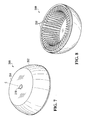
- FIG. 5 is a top perspective view of a downlight fixture in accordance with another embodiment
- FIG. 6 is partially sectioned side view of the downlight fixture of FIG. 5 .
- FIG. 7 is a top perspective view of a firestop element of the downlight fixture of FIG. 5 .
- FIG. 8 is a bottom perspective view of the firestop element of FIG. 7 .
- FIG. 11 is a top perspective view of a downlight fixture in accordance with another embodiment
- FIG. 12B is a schematic cross-sectional view of the downlight fixture of FIG. 12A showing a firestop element in a deployed position
- FIG. 13 is a top perspective view of the firestop element of FIG. 12A .
- FIG. 14B is a schematic cross-sectional view of the downlight fixture of FIG. 13 A showing a firestop element in a deployed position
- FIG. 15 is a bottom perspective view of the firestop element and support plate of FIG. 14A .
- FIG. 16A is a schematic cross-sectional view of a downlight fixture in accordance with another embodiment
- FIG. 18A is a schematic cross-sectional view of a downlight fixture in accordance with another embodiment
- FIG. 18B is a schematic cross-sectional view of the downlight fixture of FIG. 18A showing a firestop element in a deployed position
- FIG. 19A is a partially cut away top perspective view of the downlight fixture of FIG. 18A .
- FIG. 19B is an exploded view of a portion of the downlight fixture of FIG. 19A .
- FIG. 19C is an exploded view of a portion of the downlight fixture of FIG. 19A showing a firestop element in a deployed position
- FIG. 20A is a schematic cross-sectional view of a downlight fixture in accordance with another embodiment
- FIG. 20B is a schematic cross-sectional view of the downlight fixture of FIG. 20A showing a firestop element in a deployed position
- FIG. 21 is a top perspective view of the downlight fixture of FIG. 20B .
- FIG. 22A is a schematic cross-sectional view of a downlight fixture in accordance with another embodiment
- FIG. 22B is a schematic cross-sectional view of the downlight fixture of FIG. 22A showing a firestop element in a deployed position
- FIG. 23 is a top perspective view of the downlight fixture of FIG. 22B
- FIG. 24A is a schematic cross-sectional view of a downlight fixture in accordance with another embodiment
- FIG. 24B is a schematic cross-sectional view of the downlight fixture of FIG. 24A showing a firestop element in a deployed position
- FIG. 24C is a top perspective view of a portion of the downlight fixture of FIG. 24A .
- FIG. 25 is a top perspective view of the downlight fixture of FIG. 24B .
- FIG. 26 is a schematic cross-sectional view of a downlight fixture in accordance with another embodiment showing a firestop element in a deployed position.
- a downlight fixture 50 has a metal light can 52 joined to a rectangular metal base 54 .
- the base also supports wiring box 56 which, if the light fixture is used with an electrical gas discharge light, may also include a ballast.
- the light can 52 has a body 58 shaped as a cylindrical sleeve and an end cap 60 which is joined to the body by rivets 62 .
- a support plate 64 disposed within the light can has a depending slotted tongue 66 that rides on a threaded peg 68 projecting radially inwardly from body 58 .
- a wing nut 70 received on the threaded peg frictionally clamps the slotted tongue to the light can body 58 .
- the slotted tongue 66 may be slid along the peg 68 to adjust the height of the plate 64 within the light can.
- a light mount namely socket 72 , is mounted to the plate 64 and a light bulb 74 may be screwed into the light socket.
- the light can end cap 60 has a central opening 76 through which an electrical conductor 78 , originating at the wiring box 56 , extends.
- a firestop element 80 is supported on the plate 64 .
- Element 80 has a diameter similar to the inside diameter of the light can body 58 .
- the firestop element is an annular disk with a central opening 82 .
- the disk has a plurality of regularly spaced lands 86 on a face of the disk with a void 88 extending between each pair of lands.
- the voids are in the nature of radially elongated axial through slots to define a plurality of identical regularly spaced radially extending ribs 92 , with a rib between each pair of slots.
- the bottom surface of the ribs are the lands and the ribs connect to each other at the outer and inner peripheries of the annular disk.
- the central opening 82 allows the element to be fitted over the light socket 72 .
- a firestop ring 90 may extend about the base of the light can 52 and be supported on rectangular base 54 .
- Both the firestop element 80 and firestop ring 90 are fabricated of an intumescent flame retardant (IFR) that includes one or more IFR polymer composites.
- the firestop element may be rigid or elastomeric.
- Suitable IFR polymer composites may include base polymers, fire retardants, and blowing agents. If the base polymers are inherently fire retardant, such as polyvinyl chloride (PVC), chlorinated polyvinyl chloride (CPVC), halogenated polyethylene Neoprene and phenolic resin, then the fire retardants can be omitted from the composite. Synergists such as antimony oxides and/or zinc borate can be added to improve the fire retardancy of a composite.
- Char-forming agents can be added to promote charring and increase yield (i.e., final volume after intumescence), and thereby improve the fire retardancy and thermal insulation of a composite.
- other components such as smoke suppressants, pigments, and compatibilizers such as maleic anhydride grafted polyolefin and organofunctional silanes can also be added.
- Suitable fire retardants include, but are not limited to, polymeric halogen, monomeric halogen, alumina trihydrate, magnesium di-hydroxide, mica, talc, calcium carbonate, hydroxycarbonates, phosphorus compounds, red phosphorus, borate compounds, sulfur compounds, nitrogen compounds, silica, and/or various metal oxides. Other suitable fire retardants will also be apparent to those of ordinary skill in the art.
- the concentration of the fire retardants in a composite generally varies from 5 wt % to 55 wt %.
- the voids 88 of element 80 assist in allowing heat to dissipate in the light can.
- the polymer in the composite of firestop elements 80 and 90 may begin to soften.
- base 54 will support element 90 and plate 64 will support element 80 .
- the elements 80 and 90 will begin to expand and melt forming an outer layer of char.
- the voids 88 and ribs 92 of element 80 increase the surface area of the disk as compared with that of a solid disk.
- the IFR material of element 80 will react more quickly if the external temperature reaches the SET temperature, and therefore expand more quickly, than would similar IFR material of a similarly sized solid disk.
- element 80 The thickness of element 80 and the volume of material of the element are chosen so that element 80 will expand to plug the top of the light can 52 .
- Element 90 is sized so that it will expand to close off any gap between base 54 and light can 52 as well as the gap between the light can 52 and the opening through the ceiling.
- firestop element 80 could have a different pattern of lands and voids and still assist in heat dissipation in the light can during normal operation as well as presenting an increased surface area that would increase the speed of intumescence.
- element 80 may have other surface patterns.
- each of these further embodiments has at least one firestop element with a composition as has been described for firestop elements 80 and 90 .
- FIG. 4 illustrates a further embodiment where downlight fixture 100 differs from downlight fixture 50 of FIGS. 1 to 3 in the addition of a firestop sleeve 190 in place of the firestop ring 90 of FIGS. 1 to 3 .
- Sleeve 190 has a sleeve portion 172 surrounding the body 58 of the light can 52 and a plate-like base 174 sitting atop the base 54 of the fixture 100 .
- the sleeve portion 192 has a plurality of axially elongated ribs 176 between axially elongated radially opening slots 178 .
- the sleeve tapers from a wider end 182 at plate-like base 174 to a narrower end 184 at end cap 60 of the light can 52 .
- the angle of taper may be anywhere in the range of two to ten degrees.
- the sleeve 190 may be made of the afore-described intumescent material.
- the slots 178 allow heat to dissipate from the light can such that the sleeve 190 does not significantly decrease the rate of heat dissipation from the light can.
- the firestop sleeve will first soften, and then intumesce.
- the ribs 176 increase the surface area of the firestop sleeve 190 which speeds its reaction time. Because of the taper of the sleeve, when it softens it may collapse inwardly onto the outer surface of the light can. In such instance the light can 52 will support the sleeve while it intumesces.
- the firestop disk (not shown) within the can 52 intumesces, as afore-described in connection with the first embodiment.
- firestop sleeve 190 intumesces due to a fire, it will seal up the interface between the light can 52 and base 54 and will also seal off openings in the body 58 of the light can 52 .
- the expansion ratio of the sleeve can be chosen to be sufficiently high that the intumesced sleeve can plug the opening in the ceiling.
- FIGS. 5 to 9 illustrate a further embodiment of a downlight fixture.
- like parts to those of downlight fixture 50 of FIGS. 1 to 3 have been given like reference numerals, and reference should be made to the foregoing description of downlight fixture 50 for a description of these parts and their function.
- downlight fixture 200 has a rigid firestop element 280 that is the end cap for the light can 212 .
- Element 280 is joined to the cylindrical metal body 58 of the light can in any suitable fashion, such as by rivets.
- firestop element 280 has an annular sidewall 252 and a top wall 254 .
- the annular sidewall has a plurality of identical regularly spaced inwardly projecting ribs 256 shaped as fins.
- the fins project radially inwardly toward a central axis, C, of the annular sidewall 252 and are aligned with this central axis.
- the annular sidewall tapers toward the top wall and the fins commensurately taper such that the fins have a constant radial inward extent.
- the top wall 254 has a medial hole 276 to accommodate electrical conductor 78 ( FIG. 6 ).
- ribbed element 280 allows a greater rate of heat dissipation from the light can than would a solid element having the same extent.
- the temperature of the element 280 exceeds the SET, the element expands to plug the top of the light can and char is formed to provide a thermal barrier.
- the surface area of element 280 is increased by the provision of the spaced ribs 256 and so the speed of intumescence is increased as compared with that of a solid element.
- Element 280 may soften as its temperature increases beyond the normal operating temperatures of fixture 200 but remains below SET. However, in this instance, the dome shape of element 280 assists in resisting sag.
- the ribs 256 of element 280 could be replaced by other projections that increase the surface area of the element.
- a downlight fixture 300 has a firestop element 390 surrounding the light can 352 of the fixture and resting on the fixture's rectangular base 354 .
- the firestop element 390 may be configured to have an inner periphery spaced at a short stand off from the outer periphery of both the end cap 360 and cylindrical body 358 of the light can 352 .
- Element 390 has a plurality of upper axially extending ribs 336 running from a disk-shaped top 340 of the element to a medial side wall band 342 .
- the ribs 336 are defined by axially elongated radial through slots 338 .
- a plurality of lower, shorter, axially extending ribs 346 between axially elongated radially opening slots 348 run between the medial side wall band 342 and a basal side wall band 350 of the element.
- the element 390 may taper from it basal side wall band 350 at a small angle of between two and ten degrees.
- Firestop element 390 is provided with a central opening 370 in its top disk-shaped portion 360 which accommodates a conductor 378 extending from the ballast or wiring box 356 into the light can.
- the slots 338 , 348 in the firestop element 390 assist in the dissipation of heat generated by the light. If due to a fire the temperature of the firestop element 390 exceeds the SET, the element expands to envelop the light can and char is formed to provide a thermal barrier.
- the basal band 350 of the element 390 is sized so that it will expand to close off any gap between base 354 and light can 352 .
- the surface area of element 390 is increased by the provision of the spaced ribs 336 , 346 and so the speed of intumescence is increased as compared with that of a solid element.
- Element 390 may soften as its temperature increases beyond the normal operating temperatures of fixture 300 but remains below SET. However, in this instance, the firestop element may slump inwardly to be supported by the light can. If the element 390 is tapered, this will help ensure that the element will collapse toward the light can when it softens, and will char around the can. Moreover, the medial and basal bands 342 , 350 of the element impart strength to the element which assists in keeping the ribs in place while they soften.
- modified downlight fixture 300 ′ is the same as downlight fixture 300 except that fixture 300 ′ has an external can 396 surrounding firestop element 390 with a top opening 398 to accommodate conductor 378 .
- the external can 396 may be fabricated of metal, such as steel or aluminum, and may extend in close proximity to the outer periphery of firestop element 390 . In the event of fire, the external can confines the expansion of the firestop element 390 and so assists in densifying the char resulting from intumescence of the firestop element.
- the firestop element 480 has a central opening 482 and the support plate 485 has an aligned central opening 484 .
- Fire sensitive supports namely meltable or flammable T-shaped tabs 420 have tongues inserted through slots in the body 458 of the light can 412 or, in another embodiment, the tongues are screwed into openings in the side wall of the light can so that these tongues project inwardly from the light can.
- the support plate 485 and therefore firestop element 480 , rests on the tongues of the tabs 420 .
- the tabs are fabricated of a material which melts or burns off in a fire, such as a plastic, as, for example, nylon or another thermoplastic.
- a light mount (socket) 472 is disposed within openings 482 , 484 and mounted by mounts 476 that extend through the firestop element opening 482 and attach to the light can 412 .
- An electrical conductor (not shown) extends from a wiring box or ballast (not shown) through opening 482 to the light mount.
- a light bulb 474 is mounted to the light mount.
- openings 482 , 284 have a diameter greater than that that of both the light mount 472 and the light bulb 474 .
- a firestop gasket ring 490 extends about the base of the light can 412 and is enveloped by a metal sleeve 494 .
- the element 480 and plate 485 are free to fall to past the light socket and light bulb once the tabs melt or burn off.
- the support plate 485 helps hold the intumesced firestop element and resulting char in place to block the opening.
- the intumesced firestop element blocks flames from entering the light can and possibly extending through any openings in the can. It also reduces the heat inside the can.
- LED downlight fixture 500 has a light can 512 mounted on base 554 .
- the light can 512 has a body 558 shaped as a cylindrical sleeve and an end cap 560 which is joined to the body by rivets 562 .
- An opening 556 through the base 554 below the light can is bounded by a lip 532 which extends inwardly of the basal periphery of the light can 512 .
- Plastic T-shaped tabs 520 supported by the light can 512 have tongues projecting inwardly from the light can.
- Plastic T-shaped tabs 522 supported by a heat sink 570 have tongues projecting outwardly from the heat sink.
- the tabs 522 of the heat sink rest on the tabs 520 of the light can such that the heat sink 570 is supported within the light can 512 .
- An LED light (not shown) is mounted within heat sink 570 .
- a firestop element 580 is mounted to a metal support plate 585 and the metal support plate rests on the top of the heat sink 570 .
- the firestop element 580 and support plate 585 are shown in perspective view in FIG. 15 from which it will be apparent that the firestop element has a series of disk voids 588 and the plate has a series of plate voids 589 aligned with the disk voids. Further, element 580 and the plate 585 have aligned slots 590 , 591 to accommodate a conductor that feeds to the LED light.
- An intumescent ring 490 and constraining metal sleeve 494 surround the base of the light can as described in conjunction with FIGS. 12A and 12B .
- the tabs 520 are inserted into the body 558 of the light can 512 and the heat sink is then moved into place within the body 558 .
- Tabs 522 are then inserted into the heat sink so that the tongues of tabs 522 overlie the tongues of tabs 520 whereby the heat sink is supported within body 558 of the light can 512 .
- the firestop element 580 with its support plate 585 is set in place on the top of the heat sink and the cap 560 of the light can is riveted to the light can body 558 .
- heat sink 570 (with its LED light) is no longer supported within the light can 512 and it falls away, as illustrated in FIG. 14B . Since the firestop element 580 with its support plate 585 had rested upon the heat sink, it falls with the heat sink until its fall is arrested when the periphery of the support plate 585 hits the lip 532 of the base 554 of the fixture, as is also illustrated in FIG. 14B . Thus, the lip 532 of the base 554 of the fixture acts as a limiter, limiting the fall of the firestop element and its support plate.
- this element With the firestop element now at the base of the light can, as this element intumesces, it expands to plug the can at the bottom. This blocks flames from entering the light can and possibly extending through any openings in the can; it also reduces the heat inside the can. With the voids 589 in the plate 585 aligned with the voids 588 in the disk, the disk is exposed more rapidly to a heat build up, speeding its intumescing reaction time.
- lip 532 could be replaced with spring tabs joined to base 554 . These tabs would be deflected upwardly by the heat sink when it is in place within the light can and would resiliently spring to a deployed, inwardly projecting, position when the heat sink fell away in the event of a fire such that the firestop element 580 and its support plate 585 would be arrested by the deployed hinge tabs.
- the top of the light can 612 is a steel plate 685 surrounded by a fire sensitive support, namely meltable or flammable ring 687 , which may be a thermoplastic ring.
- the ring sits atop the light can body 658 .
- the ring 687 can be held to the light can body 658 by rivets or screws and can be press fit to the steel plate.
- the plate may be solid, or if helpful for heat dissipation, apertured.
- a firestop element 680 illustrated in perspective view in FIG. 17 , is mounted to the steel plate by stand-off nibs 689 . The stand-off nibs assist in heat dissipation.
- An intumescent ring 490 and constraining metal sleeve 494 surround the base of the light can as described in conjunction with FIGS. 12A and 12B .
- meltable or flammable C-clips 620 melt and/or burn off.
- heat sink 670 with its spring clips 674 (and its LED light) is no longer supported within the light can 612 and it falls away, as illustrated in FIG. 16C .
- meltable or flammable ring 687 burns off. This removes the support for firestop element 680 and plate 685 .
- the firestop element and plate 685 fall with the heat sink until they are arrested when the periphery of the support plate 685 hits the lip 632 of the base 654 of the fixture, as is also illustrated in FIG. 16C .
- LED downlight fixture 700 has a light can 712 mounted on base 754 .
- the light can 712 has a body 758 shaped as a cylindrical sleeve and an end cap 760 which is joined to the body by rivets 762 .
- An opening 756 through the base 754 below the light can is bounded by a lip 732 which extends inwardly of the basal periphery of the light can 712 .
- a guiderail assembly 772 has vertical guiderails 774 and lugs 776 joined to a ring 778 . The guiderail assembly 772 is supported on base 754 by the lugs, which overlie lip 732 .
- Plastic clips 720 are supported by the guiderail assembly.
- a heat sink 770 (not shown in FIG. 16B ) which contains a light base 771 and an LED light 773 ( FIG. 18A ) is supported within the light can 512 by plastic T-shaped tabs 722 mounted to the heat sink with tongues projecting outwardly from the heat sink 760 into clips 720 .
- a firestop element 780 is mounted to a metal support plate 785 and the metal support plate rests on the top of the heat sink 770 .
- the firestop element has a series of through slots 781 which increase its surface area.
- the metal support plate has projecting metal tabs 779 , with one tab guided by each guiderail 774 . In consequence, firestop element 780 and its support plate 785 are constrained to slide vertically within the light can 712 .
- a firestop gasket ring 790 extends about the base of the light can 752 and is supported on base 754 .
- the firestop gasket ring 790 is enveloped by a metal sleeve 794 .
- the guiderail assembly 772 is mounted to the base 754 then the tabs 779 of metal support plate 785 are inserted into the guiderails 774 so that the firestop element 780 with its support plate 785 are slidably mounted to the guiderails.
- the heat sink 770 may be inserted into the body 758 of the light can 712 and tabs 722 inserted into the heat sink so that the tongues of the tabs 722 extend within the clips 720 whereby the heat sink is supported within body 758 of the light can 712 and the firestop element 780 with its support plate 785 rests on the top of the heat sink.
- Cap 760 of the light can is then riveted to the light can body 758 .
- the firestop element and support plate fall completely to the bottom of the can and do not somehow jam within the light can and fail to fully deploy.
- this element With the firestop element now at the base of the light can, as this element intumesces it expands to plug the can at the bottom. This blocks flames from entering the light can and possibly extending through any openings in the can; it also reduces the heat inside the can.
- the intumescent gasket ring 790 extending about the light can intumesces.
- the metal sleeve 794 constrains the ring such that the only place it can expand while it intumesces is into the interface between the light can 712 and base 754 .
- the constraining sleeve 794 also densifies the char such that the interface between the light can and base is not only plugged, but there is a strong thermal barrier at this interface.
- LED downlight fixture 800 has a cylindrical light can 812 atop a base 854 .
- the light can 812 has a body 858 shaped as a cylindrical sleeve and an end cap 860 which is joined to the body by rivets 862 .
- Plastic T-shaped tabs 820 supported by the light can 812 have tongues projecting inwardly from the light can.
- Plastic T-shaped tabs 822 supported by a heat sink 870 have tongues projecting outwardly from the heat sink.
- the tabs 822 of the heat sink rest on the tabs 820 of the light can such that the heat sink 870 is supported within the light can 812 .
- An LED light (not shown) is mounted within heat sink 870 .
- a firestop element 880 is mounted to a metal support plate 885 .
- One end 893 of each of a number of flexible cables 895 is mounted to the underside of the cap 860 of the light can 812 and the other end 897 ( FIG. 20B ) is mounted to the top of support plate 885 . Loops of excess cable sit atop the support plate.
- An intumescent ring and constraining metal sleeve may surround the base of the light can as described in conjunction with FIGS. 12A and 12B .
- tabs 820 are inserted into the light can 812 .
- the heat sink is then moved into place within the light can and tabs 822 are inserted into the heat sink so that the tongues of tabs 822 overlie the tongues of tabs 820 whereby the heat sink is supported within the light can 812 .
- the firestop element 880 with its support plate 885 is set in place on the top of the heat sink.
- the cap 860 of the light can, which is joined to the support plate 885 by cables 895 is then brought into place on top of the body 858 of the can, looping excess cable onto the mounting plate in the process. Cap 860 is then riveted in place.
- the top of the light can 912 is a steel plate 985 surrounded by a fire sensitive element, namely meltable or flammable plastic ring 987 .
- the ring sits atop the light can.
- the ring 987 can be held to the light can by rivets or screws and can be press fit to the steel plate.
- the plate 985 may be solid or, if helpful for heat dissipation, apertured.
- a firestop element 980 illustrated in perspective view in FIG. 23 , is mounted to the steel plate by stand-off nibs 989 .
- the stand-off nibs assist in heat dissipation.
- One end 993 of each of a number of flexible cables 995 is mounted to the top of plate 985 of the light can 912 and the other end 997 is mounted to the side of the light can. Excess cable drops down along the side of the light can.
- LED downlight fixture 1000 has a cylindrical metal light can 1012 atop a metal base 1054 .
- the light can 1012 has a body 1058 shaped as a cylindrical sleeve and an end cap 1060 which is joined to the body by rivets 1062 .
- Fire sensitive supports namely plastic T-shaped tabs 1020 supported by the light can 1012
- Further fire sensitive supports namely plastic T-shaped tabs 1022 supported by a heat sink 1070
- the tabs 1022 of the heat sink rest on the tabs 1020 of the light can such that the heat sink 1070 is supported within the light can 1012 .
- An LED light (not shown) is mounted within heat sink 1070 .
- a firestop element 80 rests on a metal support plate 1085 .
- the firestop 80 element is illustrated in perspective view in FIG. 3 and was described hereinbefore in conjunction with that figure.
- the metal support plate 1085 is a disk having three peripheral openings 1100 .
- One end 1093 of each of a number of flexible cables 1095 is attached to the underside of the cap 1060 of the light can 1012 by any suitable mechanism, such as by a screw (not shown) in the cap pinching the end of each cable against the cap.
- Each of these cables passes through one of the voids 88 in firestop 80 and one of the openings 1102 in support plate 1085 and then extends downwardly adjacent the inside wall of the light can, terminating in a bulbous end 1104 proximate the base of the light can.
- the bulbous end of each cable has a larger diameter than the holes 1102 through the support plate 1085 .
- An intumescent ring and constraining metal sleeve may surround the base of the light can as described in conjunction with FIGS. 12A and 12B .
- the cap 1060 of the light can is then brought into place on top of the body 1058 of the can, allowing excess cable to move through disk and plate so that the bulbous cable ends hang proximate the base of the light can 1012 . Cap 1060 is then riveted in place.
- LED downlight fixture 1100 is identical to LED downlight fixture 1000 of FIGS. 24A, 24B, and 25 except in one respect and so like parts have been designated with like reference numerals.
- the one difference between fixture 1100 and fixture 1000 is that in fixture 1100 the heat sink 1070 is joined to support plate 1085 by rivets 1108 or by any other suitable fastener.
- the heat sink and surmounted support plate 1085 with disk 80 fall until the support plate is arrested by the bulbous ends of the cables 1095 .
- the heat sink being joined to the support plate, is also arrested, as illustrated in FIG. 26 .
- This embodiment has the advantage that the risk of the heat sink causing collateral damage during a fire is reduced.
- the metal support plate on which a firestop element is mounted or upon which it rests in various of the embodiments assists in avoiding slump as the firestop element softens at elevated temperatures below the SET.
- slump may not be problematic; in such circumstances, the support plate may not be needed.
- the various firestop elements have been described as having voids to create ribs or other features which increase the surface area of the elements to improve the intumescing reaction time.
- the described firestop elements typically have regularly spaced identical features and voids, the features may differ and be irregularly spaced and reaction time can still be improved.
- reaction time of an element, and heat dissipation in the light may be sufficient without the addition of voids. Accordingly, it may sometimes be sufficient to provide a firestop element in the described embodiments which lacks voids.
- the one or more fire sensitive supports which cease to support the firestop element in some embodiments have been described as meltable or flammable tabs or as a ring. In other embodiments, different fire sensitive supports may be employed.
- the fire sensitive supports may be bimetallic elements which bend to a non-supporting position when sufficiently heated by a fire.
Priority Applications (5)
| Application Number | Priority Date | Filing Date | Title |
|---|---|---|---|
| US14/725,458 US9797563B2 (en) | 2014-11-26 | 2015-05-29 | Downlight firestop |
| PCT/CA2015/051171 WO2016082026A1 (fr) | 2014-11-26 | 2015-11-12 | Coupe-feu pour plafonnier intensif |
| US15/790,711 US10551016B2 (en) | 2014-11-26 | 2017-10-23 | Downlight firestop |
| US16/130,222 US10704751B2 (en) | 2014-11-26 | 2018-09-13 | Downlight firestop |
| US16/893,088 US11408570B2 (en) | 2014-11-26 | 2020-06-04 | Downlight firestop |
Applications Claiming Priority (2)
| Application Number | Priority Date | Filing Date | Title |
|---|---|---|---|
| US14/555,029 US9803845B2 (en) | 2014-11-26 | 2014-11-26 | Downlight firestop |
| US14/725,458 US9797563B2 (en) | 2014-11-26 | 2015-05-29 | Downlight firestop |
Related Parent Applications (1)
| Application Number | Title | Priority Date | Filing Date |
|---|---|---|---|
| US14/555,029 Continuation-In-Part US9803845B2 (en) | 2014-11-26 | 2014-11-26 | Downlight firestop |
Related Child Applications (1)
| Application Number | Title | Priority Date | Filing Date |
|---|---|---|---|
| US15/790,711 Continuation US10551016B2 (en) | 2014-11-26 | 2017-10-23 | Downlight firestop |
Publications (2)
| Publication Number | Publication Date |
|---|---|
| US20160146411A1 US20160146411A1 (en) | 2016-05-26 |
| US9797563B2 true US9797563B2 (en) | 2017-10-24 |
Family
ID=56009810
Family Applications (2)
| Application Number | Title | Priority Date | Filing Date |
|---|---|---|---|
| US14/725,458 Active 2035-07-05 US9797563B2 (en) | 2014-11-26 | 2015-05-29 | Downlight firestop |
| US15/790,711 Active 2035-03-12 US10551016B2 (en) | 2014-11-26 | 2017-10-23 | Downlight firestop |
Family Applications After (1)
| Application Number | Title | Priority Date | Filing Date |
|---|---|---|---|
| US15/790,711 Active 2035-03-12 US10551016B2 (en) | 2014-11-26 | 2017-10-23 | Downlight firestop |
Country Status (2)
| Country | Link |
|---|---|
| US (2) | US9797563B2 (fr) |
| WO (1) | WO2016082026A1 (fr) |
Cited By (7)
| Publication number | Priority date | Publication date | Assignee | Title |
|---|---|---|---|---|
| US20180119905A1 (en) * | 2014-11-26 | 2018-05-03 | Ursatech Ltd. | Downlight firestop |
| US11015785B1 (en) | 2020-02-19 | 2021-05-25 | Abl Ip Holding Llc | Light fixture system with continuous fire barrier |
| US11118769B1 (en) | 2020-02-20 | 2021-09-14 | Abl Ip Holding Llc | Rotating and tilting lighting fixtures |
| US11384929B2 (en) | 2020-09-11 | 2022-07-12 | De Brousse & Crémant Inc. | Fire rated recessed lighting fixture |
| US11408570B2 (en) | 2014-11-26 | 2022-08-09 | Ursatech Ltd. | Downlight firestop |
| USD971492S1 (en) | 2019-11-08 | 2022-11-29 | Abl Ip Holding Llc | Downlight reflector |
| US11794043B2 (en) | 2019-12-10 | 2023-10-24 | Ursatech Ltd. | Ceiling fixture firestop |
Families Citing this family (6)
| Publication number | Priority date | Publication date | Assignee | Title |
|---|---|---|---|---|
| US10363443B2 (en) * | 2016-06-30 | 2019-07-30 | Superposed Associates Llc | Passive ductwork intumescent fire damper |
| CN207407200U (zh) * | 2017-08-14 | 2018-05-25 | 佛山市威得士灯饰电器有限公司 | 嵌入式防火灯具及其防火灯壳 |
| US20190353340A1 (en) * | 2018-05-21 | 2019-11-21 | Eaton Intelligent Power Limited | Fire-Resistant Recessed Lighting Fixture |
| EP3666343A1 (fr) | 2018-12-10 | 2020-06-17 | Hilti Aktiengesellschaft | Élement ignifuge |
| US11898721B2 (en) * | 2019-09-16 | 2024-02-13 | Progress Lighting, Llc | Fire rated canless recessed luminaire |
| EP3879169B1 (fr) * | 2020-03-11 | 2022-05-04 | Georg Bechter | Support de fixation d'un corps de luminaire |
Citations (86)
| Publication number | Priority date | Publication date | Assignee | Title |
|---|---|---|---|---|
| US3955330A (en) | 1975-06-25 | 1976-05-11 | United States Gypsum Company | Smoke stop for doors |
| US4137376A (en) | 1976-11-08 | 1979-01-30 | Chloride Silent Power Limited | Sodium sulphur batteries comprising a plurality of separate cells within a container |
| GB2077382A (en) | 1980-06-04 | 1981-12-16 | Stuart Anthony Rowland | Fire-resistant sleeves |
| US4364210A (en) | 1980-05-29 | 1982-12-21 | Minnesota Mining And Manufacturing Company | Fire barrier device |
| GB2108614A (en) | 1981-07-23 | 1983-05-18 | Dixon International Ltd | Fire-seal for pipe or duct extending through wall, floor or ceiling |
| US4513173A (en) | 1983-06-07 | 1985-04-23 | Minnesota Mining And Manufacturing Company | Intumescent fire protective sheaths |
| US4630415A (en) | 1982-12-23 | 1986-12-23 | Selkirk Division Of Household Manufacturing Limited | Fire stop |
| US4754377A (en) | 1986-02-21 | 1988-06-28 | Thomas Industries, Inc. | Thermally protected recessed lighting fixture |
| US4888925A (en) | 1987-11-03 | 1989-12-26 | Harbeke Gerold J | Fire-retardant fluid coupling assembly and method |
| US4916800A (en) | 1987-11-03 | 1990-04-17 | Harbeke Gerold J | Fire-retardant fluid coupling assembly and method |
| US5058341A (en) | 1989-08-31 | 1991-10-22 | Msp Products, Inc. | Method for constructing fire-stop collar assembly and apparatus thereof |
| US5103609A (en) | 1990-11-15 | 1992-04-14 | Minnesota Mining & Manufacturing Company | Intumescable fire stop device |
| US5129201A (en) | 1991-01-14 | 1992-07-14 | National Improvement Company, Inc. | Fire safety device |
| US5174077A (en) | 1990-04-24 | 1992-12-29 | The Furukawa Electric Co., Ltd. | Fire protecting structure of channel portion of plastic piping in a fire partition |
| US5301475A (en) | 1993-03-01 | 1994-04-12 | Stefely Stephen F | Fire stop device |
| US5417019A (en) | 1993-03-11 | 1995-05-23 | Lamson & Sessions Co., | Passthrough device with firestop |
| US5452551A (en) | 1994-01-05 | 1995-09-26 | Minnesota Mining And Manufacturing Company | Tiered firestop assembly |
| EP0635665B1 (fr) | 1993-06-26 | 1997-03-12 | Friatec Ag Keramik- Und Kunststoffwerke | Dispositif pour le cloisonnement de tuyaux traversant des parois ou des plafonds |
| US5887395A (en) | 1997-09-19 | 1999-03-30 | International Protective Coatings Corp. | Firestop sleeve |
| US5950376A (en) | 1994-08-01 | 1999-09-14 | Mm Systems Corporation | Fireproofing |
| DE19934902A1 (de) | 1998-07-22 | 2000-01-27 | Uba Tec Umweltgerechte Brandsc | Abschottung von Rohren, Kabeln und Kanälen durch Wände oder Decken |
| US6105334A (en) | 1997-09-16 | 2000-08-22 | Logic Construction Systems, L.L.C. | Fire resistant lighting enclosure |
| US6176052B1 (en) | 1999-05-21 | 2001-01-23 | Tosetz Co., Ltd. | Fire retarding division penetrating member |
| US6305133B1 (en) | 1999-08-05 | 2001-10-23 | Kenneth R. Cornwall | Self sealing firestop coupling assembly |
| US6412243B1 (en) | 1997-04-30 | 2002-07-02 | Franklin S. Sutelan | Ultra-lite modular composite building system |
| US20020155348A1 (en) | 1996-05-28 | 2002-10-24 | Gitto/Global Corporation | Flame-retardant battery casing |
| EP1273841A1 (fr) | 2001-07-03 | 2003-01-08 | Pyro-Fox Brandschutzservice GmbH | Manchon d'étanchéité au feu |
| US6645278B2 (en) | 2001-11-30 | 2003-11-11 | Pyrophobic Systems Ltd. | Intumescent powder |
| US20040016190A1 (en) | 2002-07-26 | 2004-01-29 | Radke Duwayne C. | Modular device to create a passage through a partition |
| US6694684B2 (en) | 2002-04-15 | 2004-02-24 | 3M Innovative Properties Company | Pass through firestop device |
| US6725615B1 (en) | 1999-05-07 | 2004-04-27 | Promat Fyreguard Pty Ltd. | Service shut off device |
| US20040100040A1 (en) | 2000-09-19 | 2004-05-27 | Michael Sakno | Penetration fire stopping seal for containment walls and floors |
| US6747074B1 (en) | 1999-03-26 | 2004-06-08 | 3M Innovative Properties Company | Intumescent fire sealing composition |
| US20040168398A1 (en) | 2000-09-19 | 2004-09-02 | Sakno Michael Peter | Block for fire and smoker along a barrier penetrating member |
| US6790893B2 (en) | 2001-11-30 | 2004-09-14 | Pyrophobic Systems Ltd. | Compound of intumescent powder and thermoplastic material |
| US20050170238A1 (en) | 2004-02-04 | 2005-08-04 | Abu-Isa Ismat A. | Fire shielding battery case |
| US20060096207A1 (en) | 2004-10-15 | 2006-05-11 | George Spais | Collar for increasing T-ratings and performance of firestop systems |
| GB2422191A (en) | 2005-01-27 | 2006-07-19 | Rd Europe Ltd | Fire Resistant Light Fitting |
| US7080486B2 (en) | 2001-07-12 | 2006-07-25 | 3M Innovative Properties Company | Pass-through firestop device |
| US20060234119A1 (en) | 2005-04-14 | 2006-10-19 | Kruger Duane D | Apparatus and method for securing battery cell packs |
| KR20070023293A (ko) | 2005-08-24 | 2007-02-28 | 주식회사 엘지화학 | 안전성이 향상된 리튬 이차전지 |
| US20080011383A1 (en) | 2006-04-20 | 2008-01-17 | Mario Paetow | Fireproof hose |
| US7397219B2 (en) | 2004-03-08 | 2008-07-08 | Black & Decker Inc. | Battery pack for transportation and operation |
| US7465888B2 (en) | 2005-10-27 | 2008-12-16 | Hilti Aktiengesellschaft | Cast-in element for forming a leadthrough for conduits |
| US7470048B2 (en) | 2004-06-09 | 2008-12-30 | Liangju Wu | Fire-rated recessed downlight |
| US7476010B2 (en) | 2005-05-23 | 2009-01-13 | Aurora Limited | Fire rated downlights |
| US20090218130A1 (en) | 2008-02-27 | 2009-09-03 | Thomas Monden | Leadthrough for passing conduits through constructional components |
| GB2459538A (en) | 2008-05-01 | 2009-11-04 | Photonstar Led Ltd | Fire rated aluminium luminaire with heat sink |
| US7651238B2 (en) | 2007-01-10 | 2010-01-26 | O'brien Aaron | Fireproof trim and insulated lighting assembly |
| US7651248B2 (en) | 2006-12-22 | 2010-01-26 | Rd Europe Limited | Fire resistant lighting fitting |
| US7670033B2 (en) | 2007-01-11 | 2010-03-02 | Tenmat Ltd. | Fire stop for light fixture |
| US20100136404A1 (en) | 2009-08-31 | 2010-06-03 | Tesla Motors, Inc. | Thermal barrier structure for containing thermal runaway propagation within a battery pack |
| US20100136391A1 (en) | 2009-09-12 | 2010-06-03 | Tesla Motors, Inc. | Active Thermal Runaway Mitigation System for Use Within a Battery Pack |
| US7812253B2 (en) | 2004-11-15 | 2010-10-12 | E.Z. Barrier, Inc. | Fire resistant barrier |
| GB2471929A (en) * | 2009-07-17 | 2011-01-19 | Jcc Lighting Products Ltd | An intumescent electrical fitting |
| US20110064997A1 (en) | 2009-08-14 | 2011-03-17 | Justin Peskar | Impact resistant battery |
| US20110088342A1 (en) | 2009-10-15 | 2011-04-21 | Specified Technologies Inc. | Firestopping bushing |
| CN101656304B (zh) | 2009-09-23 | 2011-09-14 | 连云港海水化工有限公司 | 一种无卤膨胀型阻燃蓄电池外壳料 |
| WO2011124886A2 (fr) | 2010-04-09 | 2011-10-13 | Aurora Limited | Adaptateur |
| US20110262783A1 (en) | 2010-04-27 | 2011-10-27 | Tesla Motors, Inc. | Battery Cell with Center Pin Comprised of an Intumescent Material |
| US20110281154A1 (en) | 2010-05-12 | 2011-11-17 | Vissers Daniel R | Materials for electrochemical device safety |
| US20120022201A1 (en) | 2010-06-21 | 2012-01-26 | Pyrophobic Systems, Ltd. | Firestop Composition Comprising Thermoplastic, Intumescent, and Flame Retardants |
| US20120034501A1 (en) | 2010-08-04 | 2012-02-09 | Tesla Motors, Inc. | Battery Pack Configuration to Reduce Hazards Associated with Internal Short Circuits |
| US8146305B2 (en) | 2008-07-30 | 2012-04-03 | 3M Innovative Properties Company | Pass-through firestop apparatus and methods |
| WO2012080758A2 (fr) | 2010-12-17 | 2012-06-21 | Aurora Limited | Luminaires à éclairage vers le bas amélioré. |
| US8263254B2 (en) | 2009-07-17 | 2012-09-11 | Tesla Motors, Inc. | Cell with an outer layer of intumescent material |
| US20120231318A1 (en) | 2009-11-09 | 2012-09-13 | Enerdel, Inc. | Scalable battery module |
| US20120233943A1 (en) | 2010-12-15 | 2012-09-20 | Thomas Monden | Fire Protection Module |
| US8277965B2 (en) | 2009-04-22 | 2012-10-02 | Tesla Motors, Inc. | Battery pack enclosure with controlled thermal runaway release system |
| US20120304979A1 (en) | 2010-11-19 | 2012-12-06 | Herbert Munzenberger | Line Element Lead-Through with Support Structure |
| US8393121B2 (en) | 2008-01-16 | 2013-03-12 | Beele Engineering B.V. | Fire-stop system for placement in a conduit through which a thermally weakenable pipe extends, method for placing the system and conduit provided with such a system |
| US20130061545A1 (en) | 2010-03-01 | 2013-03-14 | Rolf Kuhn Gmbh | Firestop collar |
| CA2786202A1 (fr) | 2011-09-20 | 2013-03-20 | Hilti Aktiengesellschaft | Collier coupe-feu |
| GB2495009A (en) | 2012-10-05 | 2013-03-27 | Orluna Led Technologies Ltd | Fire containment mechanism |
| WO2013045937A2 (fr) | 2011-09-30 | 2013-04-04 | Danmedical Ltd | Améliorations apportées à un appareil médical et à des accessoires |
| US20130086857A1 (en) | 2011-10-05 | 2013-04-11 | Hilti Aktiengesellschaft | Bracket for a firestop collar and use of this bracket |
| US20130104474A1 (en) | 2011-10-26 | 2013-05-02 | James Alan Klein | Fire rated radius wall structure |
| US20130118102A1 (en) | 2009-09-21 | 2013-05-16 | California Expanded Metal Products Company | Wall gap fire block device, system and method |
| US20130143076A1 (en) | 2011-12-02 | 2013-06-06 | GM Global Technology Operations LLC | Materials and methods for retarding or preventing thermal runaway in batteries |
| DE202012003405U1 (de) | 2012-04-04 | 2013-07-05 | Doyma Gmbh & Co. | Profiliertes Brandschutz-Wickelband |
| US20130247487A1 (en) | 2006-03-16 | 2013-09-26 | Bruce H. Turner | Nail plate and cable protection sleeve for building framing |
| WO2013145790A1 (fr) | 2012-03-30 | 2013-10-03 | 積水化学工業株式会社 | Feuille de composition de résine thermiquement expansible, contenant une résine époxy, et procédé pour construire une structure de pénétration pour un compartiment ignifugé |
| WO2014013265A1 (fr) | 2012-07-20 | 2014-01-23 | Aurora Limited | Puits thermique perfectionné |
| GB2515649A (en) | 2014-06-09 | 2014-12-31 | Kosnic Uk Ltd | Fire resistant downlight |
| GB2517222A (en) | 2013-10-25 | 2015-02-18 | Ecoled Ltd | A light fitting |
| US9089716B2 (en) | 2012-03-12 | 2015-07-28 | Valencia Technologies Corporation | Circuits and methods for using a high impedance, thin, coin-cell type battery in an implantable electroacupuncture device |
Family Cites Families (2)
| Publication number | Priority date | Publication date | Assignee | Title |
|---|---|---|---|---|
| US9803845B2 (en) * | 2014-11-26 | 2017-10-31 | Ursatech Ltd. | Downlight firestop |
| US9797563B2 (en) * | 2014-11-26 | 2017-10-24 | Ursatech Ltd. | Downlight firestop |
-
2015
- 2015-05-29 US US14/725,458 patent/US9797563B2/en active Active
- 2015-11-12 WO PCT/CA2015/051171 patent/WO2016082026A1/fr active Application Filing
-
2017
- 2017-10-23 US US15/790,711 patent/US10551016B2/en active Active
Patent Citations (95)
| Publication number | Priority date | Publication date | Assignee | Title |
|---|---|---|---|---|
| US3955330A (en) | 1975-06-25 | 1976-05-11 | United States Gypsum Company | Smoke stop for doors |
| US4137376A (en) | 1976-11-08 | 1979-01-30 | Chloride Silent Power Limited | Sodium sulphur batteries comprising a plurality of separate cells within a container |
| US4364210A (en) | 1980-05-29 | 1982-12-21 | Minnesota Mining And Manufacturing Company | Fire barrier device |
| GB2077382A (en) | 1980-06-04 | 1981-12-16 | Stuart Anthony Rowland | Fire-resistant sleeves |
| GB2108614A (en) | 1981-07-23 | 1983-05-18 | Dixon International Ltd | Fire-seal for pipe or duct extending through wall, floor or ceiling |
| US4630415A (en) | 1982-12-23 | 1986-12-23 | Selkirk Division Of Household Manufacturing Limited | Fire stop |
| US4513173A (en) | 1983-06-07 | 1985-04-23 | Minnesota Mining And Manufacturing Company | Intumescent fire protective sheaths |
| US4754377A (en) | 1986-02-21 | 1988-06-28 | Thomas Industries, Inc. | Thermally protected recessed lighting fixture |
| US4888925A (en) | 1987-11-03 | 1989-12-26 | Harbeke Gerold J | Fire-retardant fluid coupling assembly and method |
| US4916800A (en) | 1987-11-03 | 1990-04-17 | Harbeke Gerold J | Fire-retardant fluid coupling assembly and method |
| US5058341A (en) | 1989-08-31 | 1991-10-22 | Msp Products, Inc. | Method for constructing fire-stop collar assembly and apparatus thereof |
| US5174077A (en) | 1990-04-24 | 1992-12-29 | The Furukawa Electric Co., Ltd. | Fire protecting structure of channel portion of plastic piping in a fire partition |
| US5103609A (en) | 1990-11-15 | 1992-04-14 | Minnesota Mining & Manufacturing Company | Intumescable fire stop device |
| US5129201A (en) | 1991-01-14 | 1992-07-14 | National Improvement Company, Inc. | Fire safety device |
| US5301475A (en) | 1993-03-01 | 1994-04-12 | Stefely Stephen F | Fire stop device |
| US5417019A (en) | 1993-03-11 | 1995-05-23 | Lamson & Sessions Co., | Passthrough device with firestop |
| EP0635665B1 (fr) | 1993-06-26 | 1997-03-12 | Friatec Ag Keramik- Und Kunststoffwerke | Dispositif pour le cloisonnement de tuyaux traversant des parois ou des plafonds |
| US5452551A (en) | 1994-01-05 | 1995-09-26 | Minnesota Mining And Manufacturing Company | Tiered firestop assembly |
| US5950376A (en) | 1994-08-01 | 1999-09-14 | Mm Systems Corporation | Fireproofing |
| US20020155348A1 (en) | 1996-05-28 | 2002-10-24 | Gitto/Global Corporation | Flame-retardant battery casing |
| US6412243B1 (en) | 1997-04-30 | 2002-07-02 | Franklin S. Sutelan | Ultra-lite modular composite building system |
| US6105334A (en) | 1997-09-16 | 2000-08-22 | Logic Construction Systems, L.L.C. | Fire resistant lighting enclosure |
| US5887395A (en) | 1997-09-19 | 1999-03-30 | International Protective Coatings Corp. | Firestop sleeve |
| DE19934902A1 (de) | 1998-07-22 | 2000-01-27 | Uba Tec Umweltgerechte Brandsc | Abschottung von Rohren, Kabeln und Kanälen durch Wände oder Decken |
| US6747074B1 (en) | 1999-03-26 | 2004-06-08 | 3M Innovative Properties Company | Intumescent fire sealing composition |
| US6725615B1 (en) | 1999-05-07 | 2004-04-27 | Promat Fyreguard Pty Ltd. | Service shut off device |
| US6176052B1 (en) | 1999-05-21 | 2001-01-23 | Tosetz Co., Ltd. | Fire retarding division penetrating member |
| US6305133B1 (en) | 1999-08-05 | 2001-10-23 | Kenneth R. Cornwall | Self sealing firestop coupling assembly |
| US6336297B1 (en) | 1999-08-05 | 2002-01-08 | Kenneth R. Cornwall | Self sealing firestop coupling assembly |
| US20040168398A1 (en) | 2000-09-19 | 2004-09-02 | Sakno Michael Peter | Block for fire and smoker along a barrier penetrating member |
| US20040100040A1 (en) | 2000-09-19 | 2004-05-27 | Michael Sakno | Penetration fire stopping seal for containment walls and floors |
| EP1273841A1 (fr) | 2001-07-03 | 2003-01-08 | Pyro-Fox Brandschutzservice GmbH | Manchon d'étanchéité au feu |
| US7080486B2 (en) | 2001-07-12 | 2006-07-25 | 3M Innovative Properties Company | Pass-through firestop device |
| US6645278B2 (en) | 2001-11-30 | 2003-11-11 | Pyrophobic Systems Ltd. | Intumescent powder |
| US6790893B2 (en) | 2001-11-30 | 2004-09-14 | Pyrophobic Systems Ltd. | Compound of intumescent powder and thermoplastic material |
| US6694684B2 (en) | 2002-04-15 | 2004-02-24 | 3M Innovative Properties Company | Pass through firestop device |
| US20040016190A1 (en) | 2002-07-26 | 2004-01-29 | Radke Duwayne C. | Modular device to create a passage through a partition |
| US20050170238A1 (en) | 2004-02-04 | 2005-08-04 | Abu-Isa Ismat A. | Fire shielding battery case |
| US7486047B2 (en) | 2004-03-08 | 2009-02-03 | Black & Decker Inc. | Battery pack shipping method |
| US7397219B2 (en) | 2004-03-08 | 2008-07-08 | Black & Decker Inc. | Battery pack for transportation and operation |
| US7470048B2 (en) | 2004-06-09 | 2008-12-30 | Liangju Wu | Fire-rated recessed downlight |
| US20060096207A1 (en) | 2004-10-15 | 2006-05-11 | George Spais | Collar for increasing T-ratings and performance of firestop systems |
| US7913468B2 (en) | 2004-10-15 | 2011-03-29 | George A Spais | Collar for increasing T-ratings and performance of firestop systems |
| US7812253B2 (en) | 2004-11-15 | 2010-10-12 | E.Z. Barrier, Inc. | Fire resistant barrier |
| GB2422191A (en) | 2005-01-27 | 2006-07-19 | Rd Europe Ltd | Fire Resistant Light Fitting |
| US20060234119A1 (en) | 2005-04-14 | 2006-10-19 | Kruger Duane D | Apparatus and method for securing battery cell packs |
| US7476010B2 (en) | 2005-05-23 | 2009-01-13 | Aurora Limited | Fire rated downlights |
| US7954974B2 (en) | 2005-05-23 | 2011-06-07 | Aurora Limited | Fire rated downlights |
| KR20070023293A (ko) | 2005-08-24 | 2007-02-28 | 주식회사 엘지화학 | 안전성이 향상된 리튬 이차전지 |
| US7465888B2 (en) | 2005-10-27 | 2008-12-16 | Hilti Aktiengesellschaft | Cast-in element for forming a leadthrough for conduits |
| US20130247487A1 (en) | 2006-03-16 | 2013-09-26 | Bruce H. Turner | Nail plate and cable protection sleeve for building framing |
| US20080011383A1 (en) | 2006-04-20 | 2008-01-17 | Mario Paetow | Fireproof hose |
| US7651248B2 (en) | 2006-12-22 | 2010-01-26 | Rd Europe Limited | Fire resistant lighting fitting |
| US7651238B2 (en) | 2007-01-10 | 2010-01-26 | O'brien Aaron | Fireproof trim and insulated lighting assembly |
| US7670033B2 (en) | 2007-01-11 | 2010-03-02 | Tenmat Ltd. | Fire stop for light fixture |
| US8393121B2 (en) | 2008-01-16 | 2013-03-12 | Beele Engineering B.V. | Fire-stop system for placement in a conduit through which a thermally weakenable pipe extends, method for placing the system and conduit provided with such a system |
| US20090218130A1 (en) | 2008-02-27 | 2009-09-03 | Thomas Monden | Leadthrough for passing conduits through constructional components |
| GB2459538A (en) | 2008-05-01 | 2009-11-04 | Photonstar Led Ltd | Fire rated aluminium luminaire with heat sink |
| US8146305B2 (en) | 2008-07-30 | 2012-04-03 | 3M Innovative Properties Company | Pass-through firestop apparatus and methods |
| US8367233B2 (en) | 2009-04-22 | 2013-02-05 | Tesla Motors, Inc. | Battery pack enclosure with controlled thermal runaway release system |
| US8277965B2 (en) | 2009-04-22 | 2012-10-02 | Tesla Motors, Inc. | Battery pack enclosure with controlled thermal runaway release system |
| GB2471929A (en) * | 2009-07-17 | 2011-01-19 | Jcc Lighting Products Ltd | An intumescent electrical fitting |
| US8263254B2 (en) | 2009-07-17 | 2012-09-11 | Tesla Motors, Inc. | Cell with an outer layer of intumescent material |
| US20110064997A1 (en) | 2009-08-14 | 2011-03-17 | Justin Peskar | Impact resistant battery |
| US20100136404A1 (en) | 2009-08-31 | 2010-06-03 | Tesla Motors, Inc. | Thermal barrier structure for containing thermal runaway propagation within a battery pack |
| US20100136391A1 (en) | 2009-09-12 | 2010-06-03 | Tesla Motors, Inc. | Active Thermal Runaway Mitigation System for Use Within a Battery Pack |
| US20130118102A1 (en) | 2009-09-21 | 2013-05-16 | California Expanded Metal Products Company | Wall gap fire block device, system and method |
| CN101656304B (zh) | 2009-09-23 | 2011-09-14 | 连云港海水化工有限公司 | 一种无卤膨胀型阻燃蓄电池外壳料 |
| US20110088342A1 (en) | 2009-10-15 | 2011-04-21 | Specified Technologies Inc. | Firestopping bushing |
| US8397452B2 (en) | 2009-10-15 | 2013-03-19 | Specified Technologies Inc. | Firestopping bushing |
| US20120231318A1 (en) | 2009-11-09 | 2012-09-13 | Enerdel, Inc. | Scalable battery module |
| US20130061545A1 (en) | 2010-03-01 | 2013-03-14 | Rolf Kuhn Gmbh | Firestop collar |
| WO2011124886A2 (fr) | 2010-04-09 | 2011-10-13 | Aurora Limited | Adaptateur |
| US20110262783A1 (en) | 2010-04-27 | 2011-10-27 | Tesla Motors, Inc. | Battery Cell with Center Pin Comprised of an Intumescent Material |
| US20110281154A1 (en) | 2010-05-12 | 2011-11-17 | Vissers Daniel R | Materials for electrochemical device safety |
| US20120022201A1 (en) | 2010-06-21 | 2012-01-26 | Pyrophobic Systems, Ltd. | Firestop Composition Comprising Thermoplastic, Intumescent, and Flame Retardants |
| US20120034501A1 (en) | 2010-08-04 | 2012-02-09 | Tesla Motors, Inc. | Battery Pack Configuration to Reduce Hazards Associated with Internal Short Circuits |
| US20120304979A1 (en) | 2010-11-19 | 2012-12-06 | Herbert Munzenberger | Line Element Lead-Through with Support Structure |
| US20120233943A1 (en) | 2010-12-15 | 2012-09-20 | Thomas Monden | Fire Protection Module |
| WO2012080758A2 (fr) | 2010-12-17 | 2012-06-21 | Aurora Limited | Luminaires à éclairage vers le bas amélioré. |
| CA2786202A1 (fr) | 2011-09-20 | 2013-03-20 | Hilti Aktiengesellschaft | Collier coupe-feu |
| EP2572760A2 (fr) | 2011-09-20 | 2013-03-27 | HILTI Aktiengesellschaft | Manchette pare-feu |
| US20140077043A1 (en) | 2011-09-20 | 2014-03-20 | Hilti Aktiengesellschaft | Firestop collar |
| WO2013045937A2 (fr) | 2011-09-30 | 2013-04-04 | Danmedical Ltd | Améliorations apportées à un appareil médical et à des accessoires |
| US20130086857A1 (en) | 2011-10-05 | 2013-04-11 | Hilti Aktiengesellschaft | Bracket for a firestop collar and use of this bracket |
| US20130104474A1 (en) | 2011-10-26 | 2013-05-02 | James Alan Klein | Fire rated radius wall structure |
| US20130143076A1 (en) | 2011-12-02 | 2013-06-06 | GM Global Technology Operations LLC | Materials and methods for retarding or preventing thermal runaway in batteries |
| US9089716B2 (en) | 2012-03-12 | 2015-07-28 | Valencia Technologies Corporation | Circuits and methods for using a high impedance, thin, coin-cell type battery in an implantable electroacupuncture device |
| WO2013145790A1 (fr) | 2012-03-30 | 2013-10-03 | 積水化学工業株式会社 | Feuille de composition de résine thermiquement expansible, contenant une résine époxy, et procédé pour construire une structure de pénétration pour un compartiment ignifugé |
| DE202012003405U1 (de) | 2012-04-04 | 2013-07-05 | Doyma Gmbh & Co. | Profiliertes Brandschutz-Wickelband |
| DE102013203173A1 (de) | 2012-04-04 | 2013-10-10 | Doyma Gmbh & Co | Profiliertes Brandschutz-Wickelband |
| WO2014013265A1 (fr) | 2012-07-20 | 2014-01-23 | Aurora Limited | Puits thermique perfectionné |
| GB2495009A (en) | 2012-10-05 | 2013-03-27 | Orluna Led Technologies Ltd | Fire containment mechanism |
| GB2517222A (en) | 2013-10-25 | 2015-02-18 | Ecoled Ltd | A light fitting |
| GB2515649A (en) | 2014-06-09 | 2014-12-31 | Kosnic Uk Ltd | Fire resistant downlight |
Non-Patent Citations (20)
| Title |
|---|
| ENIA (Energy Networks & Industrial Applications), "Fire stop barriers FIRE-Stop", retrieved Dec. 10, 2013 at: http://www.enia.gr/wp-content/uploads/2012/07/FireBarriersRaytechCatal-SIGGR.pdf, (7 pages). |
| ENIA (Energy Networks & Industrial Applications), "Fire stop barriers FIRE-Stop", retrieved Dec. 10, 2013 at: http://www.enia.gr/wp-content/uploads/2012/07/FireBarriersRaytechCatal—SIGGR.pdf, (7 pages). |
| Fischer Fixing Systems, "Fischer Conduit intumescent-FCi", retrieved Dec. 10, 2013 at: https://www.byko.is/media/fischer/15---fischer-Conduit-Intumescent.pdf, (1 page). |
| Fischer Fixing Systems, "Fischer Conduit intumescent—FCi", retrieved Dec. 10, 2013 at: https://www.byko.is/media/fischer/15—-—fischer—Conduit—Intumescent.pdf, (1 page). |
| ISE Fire Products & Services Ltd., "Intumescent Fire Protection Products", 2013, retrieved Sep. 26, 2013 at: http://www.isefireproducts.co.uk/intumescent-products, (2 pages). |
| Kidde Fire Protection Services, "Intumescent Fire Seals Product Range", retrieved Sep. 26, 2013 at: http://www.kiddefps.com/utcfs/ws-407/Assets/Intuniescent%20Fire%20Seals.pdf, (31 pages). |
| Machine-generated English translation by EPO and Google, Description DE19934902, Haupt, Gabriele, "The invention relates to a foreclosure of pipes, cables and ducts through walls or ceilings, as well as joints, columns and wall openings", Jan. 27, 2000 (7 pages). |
| Machine-generated English translation by EPO and Google, Description of DE102013203173, Chikatimalla, Rajesh, "The invention relates to a wrapping tape for the fire-resistant sealing of pipe passages, with a first and an opposite second side having an intumescent material under heat", Oct. 10, 2013 (29 pages). |
| Machine-generated English translation by EPO and Google, Description of DE202012003405, Doyma GMBH & Co., "The invention relates to a wrapping tape for the fire-resistant sealing of pipe passages, with a first and an opposite second side having an intumescent material under heat", Aug. 29, 2013 (33 pages). |
| Machine-generated English translation by EPO and Google, Description of EP1273841, Züll, Armin, "The invention relates to a fire sleeve", Jan. 8, 2003 (11 pages). |
| Pemko Manufacturing Co., Inc., "Adhesive Gasketing (AG): Adhesive-Backed Fire/Smoke Gasketing", retrieved Sep. 26, 2013 at:http://www.pemko.com/index.cfm?event=products. productListing&searchNarne=Search+by+Pemko+Product+Number&openFilter=loadPemkoPartNumberSearch&partNumber=s773&partCategoryIds=S773D%3A895, (6 pages). |
| PFC Corofil, "PFC Corofil Intemescent Conduit", retrieved Dec. 10, 2013 at: http://www.pfc-corofil.com/sites/default/files/products/downloads/pfc-corofil-intumescent-conduit.pdf, (1 page). |
| PFC Corofil, "PFC Corofil Intemescent Conduit", retrieved Dec. 10, 2013 at: http://www.pfc-corofil.com/sites/default/files/products/downloads/pfc—corofil—intumescent—conduit.pdf, (1 page). |
| Proquest Dialog, Flame Retardancy News 14.11 (Nov. 2004), "Great Lakes Intros New Intumescents", retrieved from web page: http://search.proquest.com/professional/docview/671320957/141D2914C631D147EDD/6 . . .; Nov. 18, 2013 (2 pages). |
| Tesla Motors Club, "Amazing Core Tesla Battery IP-18650 Cell" retrieved from web page: http://www.teslamotorsclub.com/showthread.php/17456-Amazing-Core-Tesla Battery-IP . . .; Nov. 18, 2013 (10 pages). |
| Tesla Motors Club, "Amazing Core Tesla Battery IP—18650 Cell" retrieved from web page: http://www.teslamotorsclub.com/showthread.php/17456-Amazing-Core-Tesla Battery-IP . . .; Nov. 18, 2013 (10 pages). |
| The Sparks Direct Blog, "Aurora Fire Rated Downlights: How are they tested and how do they work?", retrieved Sep. 26, 2013 at: http://blog.sparksdirect.co.uk/tag/building-regulations/, (8 pages). |
| Trademark Hardware, "Adhesive Weatherstrip, 5/16″ Wide Silicone and Intumescent Fin", retrieved at: Sep. 26, 2013 at: http://www.tmhardware.com/Adhesive-Weatherstrip-Gasketing-Intumescent-Fin.html, (2pages). |
| Tremco Illbruck Coating Ltd., "B600 Intumescent Pipe Sleeve", Jun. 2010, retrieved Dec. 10, 2013 at: http://www.nullifirefirestopping.co.uk/celumdb/documents/Nullifire-B600-DS-GB-19530.pdf, (4 pages). |
| Tremco Illbruck Coating Ltd., "B600 Intumescent Pipe Sleeve", Jun. 2010, retrieved Dec. 10, 2013 at: http://www.nullifirefirestopping.co.uk/celumdb/documents/Nullifire—B600—DS—GB—19530.pdf, (4 pages). |
Cited By (8)
| Publication number | Priority date | Publication date | Assignee | Title |
|---|---|---|---|---|
| US20180119905A1 (en) * | 2014-11-26 | 2018-05-03 | Ursatech Ltd. | Downlight firestop |
| US10551016B2 (en) * | 2014-11-26 | 2020-02-04 | Ursatech Ltd. | Downlight firestop |
| US11408570B2 (en) | 2014-11-26 | 2022-08-09 | Ursatech Ltd. | Downlight firestop |
| USD971492S1 (en) | 2019-11-08 | 2022-11-29 | Abl Ip Holding Llc | Downlight reflector |
| US11794043B2 (en) | 2019-12-10 | 2023-10-24 | Ursatech Ltd. | Ceiling fixture firestop |
| US11015785B1 (en) | 2020-02-19 | 2021-05-25 | Abl Ip Holding Llc | Light fixture system with continuous fire barrier |
| US11118769B1 (en) | 2020-02-20 | 2021-09-14 | Abl Ip Holding Llc | Rotating and tilting lighting fixtures |
| US11384929B2 (en) | 2020-09-11 | 2022-07-12 | De Brousse & Crémant Inc. | Fire rated recessed lighting fixture |
Also Published As
| Publication number | Publication date |
|---|---|
| WO2016082026A1 (fr) | 2016-06-02 |
| US10551016B2 (en) | 2020-02-04 |
| US20160146411A1 (en) | 2016-05-26 |
| US20180119905A1 (en) | 2018-05-03 |
Similar Documents
| Publication | Publication Date | Title |
|---|---|---|
| US10551016B2 (en) | Downlight firestop | |
| US9803845B2 (en) | Downlight firestop | |
| US11408570B2 (en) | Downlight firestop | |
| US9089726B1 (en) | Passthrough firestops | |
| US9752765B2 (en) | Fire rated recessed lighting assembly | |
| US9673597B2 (en) | Wall clamping junction box | |
| US20120022201A1 (en) | Firestop Composition Comprising Thermoplastic, Intumescent, and Flame Retardants | |
| US11794043B2 (en) | Ceiling fixture firestop | |
| KR102020794B1 (ko) | 방염 케이블 트레이 | |
| CN104641176B (zh) | 改进的散热器 | |
| US20140260016A1 (en) | Firestop apparatus | |
| GB2459538A (en) | Fire rated aluminium luminaire with heat sink | |
| KR20170004159U (ko) | 입상배관 고정용 클램프 | |
| EP2778509B1 (fr) | Éclairages à diodes électroluminescentes ignifuges | |
| JP2014007892A (ja) | 貫通部の耐火構造 | |
| US20110192470A1 (en) | Safety device for ventilating heat emitting light fittings ancillary equipment and wiring | |
| Bielinski et al. | Ceramizable silicone rubber-based composites | |
| JP5320027B2 (ja) | 耐火配管構造 | |
| WO2007011982A2 (fr) | Article en mousse comprenant une composition de perfluoropolymere additionnee d'une charge | |
| JP2009057995A (ja) | 樹脂ライニング鋼管およびこの樹脂ライニング鋼管を用いた排水配管構造 | |
| JP2019127509A (ja) | 耐火性樹脂成形体 | |
| CN213555049U (zh) | 热气溶胶自动灭火装置 | |
| MXPA04001477A (es) | Soporte de pabilo para velas resistente a la flama. | |
| KR102360609B1 (ko) | 소화용 스티커 및 이를 가지는 조명등기구 | |
| CN210725569U (zh) | 应用于空调器上的新型防火电器盒 |
Legal Events
| Date | Code | Title | Description |
|---|---|---|---|
| AS | Assignment |
Owner name: PYROPHOBIC SYSTEMS LTD., CANADA Free format text: ASSIGNMENT OF ASSIGNORS INTEREST;ASSIGNORS:LUO, XIAOXIONG;PAGE, JOHN B.;SIGNING DATES FROM 20150920 TO 20150921;REEL/FRAME:036823/0849 |
|
| AS | Assignment |
Owner name: JAMMBCO HOLDINGS LTD, CANADA Free format text: ASSIGNMENT OF ASSIGNORS INTEREST;ASSIGNOR:PYROPHOBIC SYSTEMS LTD.;REEL/FRAME:038090/0624 Effective date: 20160314 |
|
| AS | Assignment |
Owner name: URSATECH LTD., CANADA Free format text: ASSIGNMENT OF ASSIGNORS INTEREST;ASSIGNOR:JAMMBCO HOLDINGS LTD;REEL/FRAME:038882/0284 Effective date: 20160531 |
|
| FEPP | Fee payment procedure |
Free format text: ENTITY STATUS SET TO SMALL (ORIGINAL EVENT CODE: SMAL) |
|
| STCF | Information on status: patent grant |
Free format text: PATENTED CASE |
|
| MAFP | Maintenance fee payment |
Free format text: PAYMENT OF MAINTENANCE FEE, 4TH YR, SMALL ENTITY (ORIGINAL EVENT CODE: M2551); ENTITY STATUS OF PATENT OWNER: SMALL ENTITY Year of fee payment: 4 |