US9736919B2 - RF power distribution device and RF power distribution method - Google Patents
RF power distribution device and RF power distribution method Download PDFInfo
- Publication number
- US9736919B2 US9736919B2 US13/750,058 US201313750058A US9736919B2 US 9736919 B2 US9736919 B2 US 9736919B2 US 201313750058 A US201313750058 A US 201313750058A US 9736919 B2 US9736919 B2 US 9736919B2
- Authority
- US
- United States
- Prior art keywords
- electrode
- power
- power distribution
- distribution device
- reactive element
- Prior art date
- Legal status (The legal status is an assumption and is not a legal conclusion. Google has not performed a legal analysis and makes no representation as to the accuracy of the status listed.)
- Active, expires
Links
Images


Classifications
-
- H—ELECTRICITY
- H05—ELECTRIC TECHNIQUES NOT OTHERWISE PROVIDED FOR
- H05H—PLASMA TECHNIQUE; PRODUCTION OF ACCELERATED ELECTRICALLY-CHARGED PARTICLES OR OF NEUTRONS; PRODUCTION OR ACCELERATION OF NEUTRAL MOLECULAR OR ATOMIC BEAMS
- H05H1/00—Generating plasma; Handling plasma
- H05H1/24—Generating plasma
- H05H1/46—Generating plasma using applied electromagnetic fields, e.g. high frequency or microwave energy
-
- H—ELECTRICITY
- H01—ELECTRIC ELEMENTS
- H01J—ELECTRIC DISCHARGE TUBES OR DISCHARGE LAMPS
- H01J37/00—Discharge tubes with provision for introducing objects or material to be exposed to the discharge, e.g. for the purpose of examination or processing thereof
- H01J37/32—Gas-filled discharge tubes
- H01J37/32009—Arrangements for generation of plasma specially adapted for examination or treatment of objects, e.g. plasma sources
- H01J37/32082—Radio frequency generated discharge
- H01J37/32091—Radio frequency generated discharge the radio frequency energy being capacitively coupled to the plasma
-
- H—ELECTRICITY
- H01—ELECTRIC ELEMENTS
- H01J—ELECTRIC DISCHARGE TUBES OR DISCHARGE LAMPS
- H01J37/00—Discharge tubes with provision for introducing objects or material to be exposed to the discharge, e.g. for the purpose of examination or processing thereof
- H01J37/32—Gas-filled discharge tubes
- H01J37/32009—Arrangements for generation of plasma specially adapted for examination or treatment of objects, e.g. plasma sources
- H01J37/32082—Radio frequency generated discharge
- H01J37/32174—Circuits specially adapted for controlling the RF discharge
- H01J37/32183—Matching circuits
-
- H—ELECTRICITY
- H03—ELECTRONIC CIRCUITRY
- H03H—IMPEDANCE NETWORKS, e.g. RESONANT CIRCUITS; RESONATORS
- H03H7/00—Multiple-port networks comprising only passive electrical elements as network components
- H03H7/38—Impedance-matching networks
- H03H7/40—Automatic matching of load impedance to source impedance
-
- H—ELECTRICITY
- H05—ELECTRIC TECHNIQUES NOT OTHERWISE PROVIDED FOR
- H05H—PLASMA TECHNIQUE; PRODUCTION OF ACCELERATED ELECTRICALLY-CHARGED PARTICLES OR OF NEUTRONS; PRODUCTION OR ACCELERATION OF NEUTRAL MOLECULAR OR ATOMIC BEAMS
- H05H1/00—Generating plasma; Handling plasma
- H05H1/24—Generating plasma
- H05H1/46—Generating plasma using applied electromagnetic fields, e.g. high frequency or microwave energy
- H05H1/4645—Radiofrequency discharges
- H05H1/466—Radiofrequency discharges using capacitive coupling means, e.g. electrodes
-
- H05H2001/4675—
-
- H05H2001/4682—
-
- H—ELECTRICITY
- H05—ELECTRIC TECHNIQUES NOT OTHERWISE PROVIDED FOR
- H05H—PLASMA TECHNIQUE; PRODUCTION OF ACCELERATED ELECTRICALLY-CHARGED PARTICLES OR OF NEUTRONS; PRODUCTION OR ACCELERATION OF NEUTRAL MOLECULAR OR ATOMIC BEAMS
- H05H2242/00—Auxiliary systems
- H05H2242/20—Power circuits
- H05H2242/26—Matching networks
Definitions
- the present invention relates to RF power distribution devices and, more particularly, to an RF power distribution device for distributing RF power impedance-matched by a single matching network to a plurality of electrodes or a plurality of positions of an electrode.
- a capacitively-coupled RF plasma device a top electrode, a source RF power source, a substrate holder for retaining a substrate, and a bias RF power source which are disposed inside a vacuum container.
- the source RF power source is applied to the top electrode
- the bias RF power source is applied to the substrate holder.
- mutual interference makes it difficult to stably perform a plasma process.
- an RF power source is applied to only one of a top electrode and a substrate holder inside a vacuum container.
- Embodiments of the present invention provide a power distribution device for simultaneously or sequentially generating capacitively-coupled plasmas through power distribution.
- the power distribution device may include an impedance matching network configured to deliver power from an RF power source; and a power distribution unit configured to distribute the output power from the impedance matching network to at least one electrode generating capacitively-coupled plasma.
- the power distribution unit may include a first reactive element connected in series to a first electrode; a variable capacitor having one end connected in parallel to the first reactive element and the first electrode and the other end grounded; and a second reactive element having one end connected to a first node where the one end of the variable capacitor and one end of the first reactive element are in contact with each other and the other end connected to a second node where a second electrode and an output terminal of the impedance matching network are connected.
- Embodiments of the present invention provide a power distribution method for simultaneously or sequentially generating capacitively-coupled plasmas through power distribution.
- the power distribution method may include setting first power, a first voltage, or a first current flowing to a first electrode disposed inside a vacuum container to generate capacitively-coupled plasma and setting second power, a second voltage, or a second current supplied to a second electrode disposed inside the vacuum container; supplying power to the first electrode and the second power from an RF power source through an impedance matching network; performing matching by operating the impedance matching network; measuring at least one of the current, the voltage, and the power flowing through the first electrode and the second electrode; and controlling the set power, the set voltage or the set current to be supplied to the first electrode and the second electrode by using a power distribution unit.
- FIGS. 1 and 2 illustrate a power distribution device according to embodiments of the present invention.
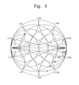
- FIGS. 3 to 5 are the Smith charts of a power distribution device according to an embodiment of the present invention.
- FIGS. 6 to 8 illustrate a power distribution rate, a real part of the total impedance, and an imaginary part of the total impedance of a power distribution device according to an embodiment of the inventive concept.
- FIG. 9 illustrates a power distribution unit according to another embodiment of the present invention.
- FIGS. 10 and 11 illustrate a power distribution device according to another embodiment of the present invention.
- FIGS. 12 and 13 illustrate a power distribution device according to another embodiment of the present invention.
- FIGS. 14 to 16 illustrate a power distribution device according to other embodiments of the present invention.
- FIGS. 17 and 18 illustrate a power distribution device according to another embodiment of the present invention.
- FIGS. 19 and 20 illustrate power distribution devices according to another embodiment of the present invention.
- FIG. 21 is a flowchart illustrating a power distribution method according to an embodiment of the present invention.
- Capacitively-coupled plasma has been widely used in deposition of polysilicon for solar cells, etching of oxide layers, and the like.
- the problem of plasma space uniformity or cleaning has emerged as substrates trend to become larger in diameter. If frequencies of RF power sources are identical to each other when the RF power sources supply power to a plurality of electrodes respectively, mutual interference of the RF power sources causes difficulty in impedance matching. Hence, there is a requirement for a power distribution device that efficiently and stably distributes power to electrodes.
- a power distribution device may distribute power to a plurality of electrodes or supply power to an electrode at a plurality of positions.
- the power distribution device may enhance plasma uniformity or process uniformity.
- the power distribution device may distribute power to the plurality of electrodes from an RF power source to generate plasma.
- the power distribution device may employ a single impedance matching network to simplify the configuration of a system.
- an impedance matching network disposed between an RF power source and a power distribution unit performs impedance matching.
- an impedance viewing the power distribution unit from an output terminal of the impedance matching network is comparatively constant irrespective of variable reactance of a power distribution unit. That is, an impedance viewing the power distribution unit from an output terminal of the impedance matching network is slightly affected by the power distribution unit.
- the impedance matching network may perform stable impedance matching, process stability and reliability may be improved.
- the power distribution unit is linearly varied depending on the capacity of a variable element and has a wide power distribution ratio within the variable range of the variable element.
- FIGS. 1 and 2 illustrate a power distribution device according to embodiments of the present invention.
- the power distribution device includes an impedance matching network 220 delivering power of an RF power source 210 and a power distribution unit 230 distributing output power of the impedance matching network 220 to at least one of first and second electrodes 240 and 250 generating capacitively-coupled plasma.
- the power distribution unit 230 includes a first reactive element 234 connected in series to the first electrode 240 , a variable capacitor 236 having one end connected in parallel to the first reactive element 234 and the first electrode 240 and the other end ground, and a second reactive element 232 having one end connected to a first node N 1 where the one end of the variable capacitor 236 and one end of the first reactive element 234 are in contact with each other and the other end connected to a second node N 2 where the second electrode 250 and an output terminal 231 of the impedance matching network 220 are connected.
- the RF power source 210 may output a sine wave of a single frequency and the frequency may be about 0.1 MHz to about 20 MHz.
- the impedance matching network 220 may be means for maximally delivering power to a load.
- a vacuum chamber 260 may be made of a metallic material, and the lid 262 of the vacuum container 260 may be a metal plate.
- the first electrode 240 and the second electrode 250 may be disposed opposite to each other.
- a substrate 252 may be mounted on the second electrode 250 .
- the first electrode 240 may generate capacitively-coupled plasma.
- the first electrode 240 may include gas distribution means.
- the first electrode 240 may receive power through the power distribution unit 230 .
- the second electrode 250 may generate capacitively-coupled plasma and apply a bias voltage to the substrate 252 .
- the second electrode 250 may be a substrate holder.
- the substrate 252 may be a semiconductor substrate or a glass substrate.
- a first measuring unit 272 may measure at least one of power, current, and voltage of the first electrode 240 .
- a second measuring unit 274 may measure at least one of power, current, and voltage of the second electrode 250 .
- the first and second measuring units 272 and 274 may include a pick-up coil for measuring current flowing to the first and second electrode 240 and 250 a voltage measuring electrode for measuring a voltage.
- a controller 270 may receive outputs of the first measuring unit 272 and the second measuring unit 274 and control the power distribution unit 230 and the RF power source 210 to control a ratio of powers or currents flowing to the first electrode 240 and the second electrode 250 .
- the controller 270 may control the power distribution unit 230 and/or the RF power source 210 by calculating power, voltage or current flowing to the first electrode 240 and/or the second electrode 250 .
- the first electrode 240 and the second electrode 250 may receive set power, voltage or current. That is, the controller 270 may supply not only comparatively power distributed to the first electrode 240 and the second electrode 250 but also an absolute value supplied to the first electrode 240 and the second electrode 250 .
- the power supplied to the second electrode 250 may decide a DC bias voltage.
- Switches 276 and 278 may be directly connected to at least one of the first and second electrodes 240 and 250 .
- the switches 276 and 278 may switch the power supplied to the first electrode 240 or the second electrode 250 .
- Each of the switches 276 and 278 may be a mechanical relay switch using solenoid or an electrical switch using a pin diode.
- the first reactive element 234 is an inductor, and the second reactive element 232 is a fixed capacitor.
- An auxiliary capacitor 237 may be provided between the second electrode 250 and the second node N 2 .
- the auxiliary capacitor 237 may be used to adjust a phase between the first electrode 240 and the second electrode 250 .
- the auxiliary electrode 237 may be a variable capacitor to which a motor is connected.
- the auxiliary electrode 237 may serve to adjust a phase between the first electrode 240 and the second electrode 250 within a certain range.
- the variable capacitor 236 may be a vacuum capacitor.
- the vacuum capacitor may be connected to the motor 239 to vary capacitance.
- the motor 239 may be controlled by the controller 270 .
- the first measuring unit 272 may be disposed between the first electrode 240 and the first reactive element 234 .
- the first measuring unit 272 may measure at least one of power, voltage, and current of the first electrode 240 .
- the second measuring unit 274 may be disposed between the second electrode 250 and the second node N 2 .
- the second measuring unit 274 may measure at least one of power, voltage, and current of the second electrode 250 .
- the controller 270 may control the variable capacitor 236 through the motor 239 such that the set power is applied to the first electrode 240 .
- the controller 270 may control the power distribution unit 230 and the RF power source 210 such that the set power, voltage or current is applied to the second electrode 250 .
- the first switch 276 may be disposed between the first electrode 240 and the first reactive element 234 .
- the first switch 276 may be connected in series to the first measuring unit 272 .
- the second switch 278 may be disposed between the second electrode 250 and the second node N 2 .
- the second switch 278 may be connected in series to the second measuring unit 274 .
- the controller 270 may control the first switch 276 may switch an electrical connection between the power distribution unit 230 and the first electrode 240 .
- the controller 270 may control the second switch 278 to switch an electrical connection between the power distribution unit 230 and the second electrode 250 .
- an impedance of a first reactive element 234 is expressed as jX S1
- an impedance of a second reactive element 232 is expressed as jX S2
- an impedance of the variable capacitor 236 is expressed as jX P .
- R represents a real part of the effective impedance Z eff and X represents an imaginary part thereof.
- FIGS. 3 to 5 are the Smith charts illustrating impedance variation caused by a power distribution device according to an embodiment of the present invention.
- an inductor is preferably selected as the first reactive element 234 to increase real resistance of the overall impedance.
- the first reactive element 234 may employ an inductor such that an imaginary part of the impedance sum of the first electrode 240 and the first reactive element 234 has a positive sign.
- the impedance variation caused by the variable capacitor 236 may increase real resistance to stably operate an impedance matching network or the like.
- the total impedance Z 12 viewed from an output terminal of the impedance matching network 220 may be a parallel connection between Z 2 and Z eff .
- impedances of imaginary parts of the Z 2 and Z eff have opposite signs, parallel resonance may occur.
- the impedance matching network 220 cannot perform impedance matching.
- an imaginary part of the impedance sum of the first electrode 240 , the first reactive element 234 , and the variable capacitor 236 is adjusted to have a positive sign, the imaginary part of the impedance of the second electrode 250 has a negative sign and thus parallel resonance may occur.
- the second reactive element 232 in order to avoid the parallel resonance, the second reactive element 232 must be decided as a capacitor of capacity where an imaginary part of Z eff has a negative sign.
- an element value is selected considering the fact that a power distribution ratio varies depending on values of the first reactive element 234 and the second reactive element 232 .
- Z eff is greater than Z 2
- the total impedance Z 12 converges to the low impedance Z 2 . Accordingly, the total impedance Z 12 becomes comparatively constant.
- the power distribution unit 230 is designed such that Z eff is made much greater than Z 2 .
- the power distribution unit 230 may provide linearity of a current distribution ratio (I 2 /I 1 ) according to the first and second reactive elements 234 and 232 and capacitance of the variable capacitor 236 .
- P incident power supplied through an impedance matching network.
- the power distribution unit 230 may supply power to only the second electrode 250 or to both the first electrode 240 and the second electrode 250 at the same time.
- the power distribution ratio or the current distribution ratio (I 2 /I 1 ) may be adjusted according to time.
- FIGS. 6 to 8 illustrate a current distribution rate, a real part of the total impedance, and an imaginary part of the total impedance of a power distribution device according to an embodiment of the inventive concept.
- an impedance of the first electrode 240 is (10-j100) ohms
- an impedance of the second electrode 250 is (10-j100) ohms
- a capacity value of the first reactive element 234 is 120 ohms
- a capacity value of the second reactive element 232 is ⁇ 230 ohm
- a current distribution ratio depending on the capacity of the variable capacitor 236 and a real part and an imaginary part of the total impedance Z 12 viewing from an output terminal of an impedance matching network are shown.
- the current ratio (I 2 /I 1 ) varies within the range from 0.6 to 3.5.
- the real part of the total impedance Z 12 is comparatively constant near 8 ohms.
- the imaginary part of the total impedance Z 12 is comparatively constant near 70 ohms.
- a first RF power source may apply power to a first electrode through a separate impedance matching network, and a second RF power source may apply power through a separate impedance matching network.
- the second RF power source cannot perform impedance matching within a short time. Thus, process stability is impaired.
- the impedance matching is maintained to achieve a stable operation even under a condition where power is not applied to the first electrode 240 or varies depending on time.
- a power distribution unit may extend to three or more loads connected in parallel to each other.
- FIG. 9 illustrates a power distribution unit according to another embodiment of the present invention. Duplicate explanations with those in FIG. 2 will be omitted.
- the power distribution unit 230 includes a first reactive element 234 a connected in series to the first electrode 240 a , a variable capacitor 236 having one end connected in parallel to the first reactive element 234 a and the first electrode 240 and the other end grounded, and a second reactive element 232 a having one end connected to a first node N 1 where one end of the variable capacitor 236 and one end of the first reactive element 234 a are in contact with each other and the other end connected to a second node N 2 where the second electrode 250 and an output terminal 331 of the impedance matching network are connected to each other.
- the first reactive element 234 a may be a fixed capacitor
- the second reactive element 232 a may be an inductor.
- the capacitively-coupled plasma apparatus may be used without worry about increase in current.
- Values of the first reactive element 234 a and the second reactive element 232 a are decided such that the impedances of imaginary parts of Z 2 and Z eff are all made negative to prevent parallel resonance of Z 2 and Z eff .
- FIGS. 10 and 11 illustrate a power distribution device according to another embodiment of the present invention.
- the power distribution device includes an impedance matching network 220 delivering power of an RF power source 210 , and at least one of first and second electrodes 240 and 250 generating capacitively-coupled plasma, and a power distribution unit 230 distributing output power of the impedance matching network 220 .
- the power distribution unit 230 includes a first reactive element 234 connected in series to the first electrode 240 , a variable capacitor 236 having one end connected in parallel to the first reactive element 234 and the first electrode 240 and the other end grounded, and a second reactive element 232 having one end connected to a first node N 1 where one end of the variable capacitor 236 and one end of the first reactive element 234 are in contact with each other and the other end connected to a second node N 2 where the second electrode 250 and an output terminal 231 of the impedance matching network 220 are connected to each other.
- the first reactive element 234 may be an inductor
- the second reactive element 232 may be a fixed capacitor.
- the power distribution unit 230 may supply power at a plurality of positions of the first and second electrodes 240 and 250 that are electrically connected to each other.
- the first and second electrodes 240 and 250 may be electrically and physically connected to each other.
- electric field intensity of the electrode may cause standing wave effect. That is, when power is supplied to the center of the electrode, an electric field at the center of the electrode and an electric field at the edge of the electrode may be different in phase and intensity.
- the electrode needs to receive the power at a plurality of positions to cancel out the standing wave effect.
- simply supplying power at a plurality of positions is limited in canceling out the standing wave effect. For this reason, supplying different powers at a plurality of positions according to the positions may enhance plasma uniformity or process uniformity.
- first power supply lines 245 a may be disposed at an edge portion of the first electrode 240 , and a second power supply line 243 a may be disposed at the center of the second electrode 250 .
- the power supplied through the second power supply line 243 a may be greater than that supplied through the first power supply line 245 a.
- FIGS. 12 and 13 illustrate a power distribution device according to another embodiment of the present invention.
- the power distribution device includes an impedance matching network 220 delivering power of an RF power source 210 and a power distribution unit 230 distributing output power of the impedance matching network 220 to at least one electrode generating capacitively-coupled plasma.
- the power distribution unit 230 includes a first reactive element 234 connected in series to the first electrode 240 , a variable capacitor 236 having one end connected in parallel to the first reactive element 234 and a first electrode 240 and the other end grounded, and a second reactive element 232 having one end connected to a first node N 1 where one end of the variable capacitor 236 and one end of the first reactive element 234 are in contact with each other and the other end connected to a second node N 2 where a second electrode 250 and an output 231 of the impedance matching network 220 are connected to each other.
- the first electrode 240 and the second electrode 250 are disposed adjacent to each other on the same plane.
- the first electrode 240 and/or the second electrode 250 may be divided into sub-electrodes 242 and 252 , respectively.
- the power distribution unit 230 distributes power to the first electrode 240 and the second electrode 250 .
- the sub-electrodes 242 constituting the first electrode 240 may be connected in parallel to each other, and the sub-electrodes 252 constituting the second electrode 250 may be connected in parallel to each other.
- the first electrode 240 may be disposed at a corner portion and the second electrode 250 may be disposed crosswise.
- the first electrode 240 may include first to fourth sub-electrodes 242
- the second electrode 250 may include first to fifth sub-electrodes 252 .
- a space between the sub-electrodes may be filled with an insulator.
- Plasma density uniformity and process uniformity may be enhanced depending on the power supplied to the first electrode 240 and the second electrode 250 .
- the first electrode 240 and/or the second electrode 250 may further include a gas distribution unit.
- the first electrode 240 and/or the second electrode 250 may include holes (not shown) and/or trenches (not shown) for hollow cathode discharge.
- FIG. 14 illustrates a power distribution device according to another embodiment of the present invention.
- the power distribution device includes an impedance matching network 220 delivering power of an RF power source 210 and a power distribution unit 230 distributing output power of the impedance matching network 220 to at least one electrode generating capacitively-coupled plasma.
- the power distribution unit 230 includes a first reactive element 234 connected in series to the first electrode 240 , a variable capacitor 236 having one end connected in parallel to the first reactive element 234 and a first electrode 240 and the other end ground, and a second reactive element 232 having one end connected to a first node N 1 where one end of the variable capacitor 236 and one end of the first reactive element 234 are in contact with each other and the other end connected to a second node N 2 where a second electrode 350 and an output of the impedance matching network 220 are connected to each other.
- the second electrode 350 may disposed on the inner sidewall of a vacuum container 260 , and the power distribution unit 230 may distribute power to the first electrode 240 and the second electrode 350 .
- the first electrode 240 may be disposed opposite to a substrate holder 255 on which a substrate 252 is mounted.
- the second electrode 350 may be disposed adjacent to the inner sidewall of the vacuum container 260 .
- the second electrode 350 may be used to enhance plasma uniformity when a plasma process is performed. Also the second electrode 350 may be used when a cleaning process of the vacuum container 260 is performed.
- FIG. 15 illustrates a power distribution device according to another embodiment of the present invention.
- the power distribution device may further include a third electrode 250 b and an auxiliary power distribution unit 230 b distributing power to the third electrode 250 b .
- the auxiliary power distribution unit 230 b may draw out power from a first node N 1 of the power distribution unit 230 .
- the auxiliary power distribution unit 230 b has the same configuration as the power distribution unit 230 .
- FIG. 16 illustrates a power distribution device according to another embodiment of the present invention.
- the power distribution device may further include a third electrode 250 c and an auxiliary power distribution unit 230 c distributing power to the third electrode 250 c .
- the auxiliary power distribution unit 230 c may draw out power from a second node N 2 of the power distribution unit 230 .
- the auxiliary power distribution unit 230 s may have the same configuration as the power distribution unit 230 .
- FIGS. 17 and 18 illustrate a power distribution device according to another embodiment of the present invention.
- the power distribution device includes a dual-frequency impedance matching network 220 a delivering powers of RF power sources 210 a and 210 b and a power distribution unit 230 distributing output power of the impedance matching network 220 a to at least one electrode generating capacitively-coupled plasma.
- the power distribution unit 230 includes a first reactive element 234 connected in series to a first electrode 240 , a variable capacitor 236 having one end connected in parallel to the first reactive element 234 and the first electrode 240 and the other end ground, and a second reactive element 232 having one end connected to a first node N 1 where one end of the variable capacitor 236 and one end of the first reactive element 234 are in contact with each other and the other end connected to a second node N 2 where the second electrode 250 and an output terminal of the impedance matching network 220 a are connected to each other.
- the RF power sources 210 a and 210 b may include a low-frequency RF power source 220 a outputting a low frequency and a high-frequency RF power source 220 b outputting a high frequency. Outputs of the low-frequency RF power source 220 a and the high-frequency RF power source 220 b are provided to the impedance matching network 220 a .
- a plurality of RF power sources having different frequencies may adjust a DC bias voltage while improving plasma density.
- the first electrode 240 and the second electrode 250 are disposed opposite to each other.
- a substrate 252 may be mounted on the second electrode 250 .
- the power distribution unit 230 may distribute power to the first electrode 240 and the second electrode 250 .
- a power distribution ratio of the first RF power source 210 a and a power distribution ratio of the second RF power source 210 b depending on the variable capacitor 236 of the power distribution unit 230 may be different from each other.
- FIG. 19 illustrates a power distribution device according to another embodiment of the present invention. Duplicate explanations with those in FIG. 18 will be omitted.
- a power distribution unit 230 supplies power at a plurality of positions of a first electrode 240 and a second electrode 340 that are electrically connected to each other.
- a ratio of the power supplied to the first electrode 240 to the power supplied to the second electrode 340 may be different depending on a frequency.
- a substrate 252 may be mounted on a substrate holder 250 c.
- FIG. 20 illustrates a power distribution device according to another embodiment of the present invention. Duplicate explanations with those in FIG. 18 will be omitted.
- a first electrode 240 and a second electrode 250 are disposed adjacent to each other on the same plane.
- the first electrode 240 or the second electrode 250 may be divided into sub-electrodes.
- a power distribution unit 220 a distributes power to the first electrode 240 and the second electrode 250 .
- FIG. 21 is a flowchart illustrating a power distribution method according to an embodiment of the present invention.
- the power distribution method include setting first power, a first voltage or first current flowing to the first electrode 240 disposed inside the vacuum container 260 to generate capacitively-coupled plasma and setting second power, a second voltage or second current supplied to a second electrode 250 disposed inside the vacuum container (S 110 ), supplying power to the first electrode 240 and the second electrode 250 from RF power source 210 through the impedance matching network 220 (S 120 ), performing matching by operating the impedance matching network 220 (S 130 ), measuring at least one of the current, the voltage, and the power flowing through the first electrode 240 and the second electrode 250 (S 140 ), and controlling the set power, the set voltage or the set current to be supplied to the first electrode 240 and the second electrode 250 by using the power distribution unit 230 (S 200 ).
- the step of controlling the set power, the set voltage or the set current to be supplied to the first electrode 240 and the second electrode 250 includes comparing power flowing to the first electrode 240 with first power (S 210 ), adjusting the power distribution unit 230 (S 220 ), comparing power flowing to the second electrode 250 with second power (S 230 ), and changing output power of the RF power source 210 (S 240 ).
- the RF power source 210 may be a plurality of RF power sources having different frequencies.
- an RF power distribution device includes one RF power source and one impedance matching network.
- the RF power distribution device can prevent mutual interference between RF power sources and stably distribute RF power to a plurality of electrodes.
- the impedance matching network can stably operate.
Landscapes
- Physics & Mathematics (AREA)
- Engineering & Computer Science (AREA)
- Plasma & Fusion (AREA)
- Chemical & Material Sciences (AREA)
- Analytical Chemistry (AREA)
- Electromagnetism (AREA)
- Spectroscopy & Molecular Physics (AREA)
- Plasma Technology (AREA)
- Drying Of Semiconductors (AREA)
Applications Claiming Priority (3)
| Application Number | Priority Date | Filing Date | Title |
|---|---|---|---|
| KR1020100073805A KR101151419B1 (ko) | 2010-07-30 | 2010-07-30 | Rf 전력 분배 장치 및 rf 전력 분배 방법 |
| KR10-2010-0073805 | 2010-07-30 | ||
| PCT/KR2011/002951 WO2012015147A2 (ko) | 2010-07-30 | 2011-04-22 | Rf 전력 분배 장치 및 rf 전력 분배 방법 |
Related Parent Applications (1)
| Application Number | Title | Priority Date | Filing Date |
|---|---|---|---|
| PCT/KR2011/002951 Continuation WO2012015147A2 (ko) | 2010-07-30 | 2011-04-22 | Rf 전력 분배 장치 및 rf 전력 분배 방법 |
Publications (2)
| Publication Number | Publication Date |
|---|---|
| US20130134877A1 US20130134877A1 (en) | 2013-05-30 |
| US9736919B2 true US9736919B2 (en) | 2017-08-15 |
Family
ID=45530552
Family Applications (1)
| Application Number | Title | Priority Date | Filing Date |
|---|---|---|---|
| US13/750,058 Active 2033-11-25 US9736919B2 (en) | 2010-07-30 | 2013-01-25 | RF power distribution device and RF power distribution method |
Country Status (4)
| Country | Link |
|---|---|
| US (1) | US9736919B2 (zh) |
| KR (1) | KR101151419B1 (zh) |
| CN (1) | CN103026800B (zh) |
| WO (1) | WO2012015147A2 (zh) |
Cited By (1)
| Publication number | Priority date | Publication date | Assignee | Title |
|---|---|---|---|---|
| TWI712342B (zh) * | 2018-06-26 | 2020-12-01 | 日商日立全球先端科技股份有限公司 | 電漿處理裝置及電漿處理方法 |
Families Citing this family (14)
| Publication number | Priority date | Publication date | Assignee | Title |
|---|---|---|---|---|
| KR20140122548A (ko) * | 2013-04-10 | 2014-10-20 | 피에스케이 주식회사 | 전력 공급 장치, 전력 공급 방법, 그리고 그를 이용한 기판 처리 장치 |
| KR101522891B1 (ko) * | 2014-04-29 | 2015-05-27 | 세메스 주식회사 | 플라즈마 발생 유닛 및 그를 포함하는 기판 처리 장치 |
| CN105228330B (zh) * | 2015-09-01 | 2018-09-14 | 沈阳拓荆科技有限公司 | 一种射频等离子体设备匹配器 |
| CN106937472A (zh) * | 2015-12-29 | 2017-07-07 | 中微半导体设备(上海)有限公司 | 等离子体处理装置及等离子体处理方法 |
| CN107180737B (zh) * | 2016-03-11 | 2019-10-08 | 北京北方华创微电子装备有限公司 | 用于实现阻抗匹配和功率分配的装置及半导体加工设备 |
| JP6554055B2 (ja) * | 2016-03-22 | 2019-07-31 | 富士フイルム株式会社 | プラズマ生成装置、プラズマ生成方法およびプラズマ処理方法 |
| KR102158668B1 (ko) * | 2016-04-22 | 2020-09-22 | 어플라이드 머티어리얼스, 인코포레이티드 | 플라즈마 한정 피쳐들을 갖는 기판 지지 페디스털 |
| US20190157048A1 (en) * | 2017-11-17 | 2019-05-23 | Taiwan Semiconductor Manufacturing Co., Ltd. | Plasma processing apparatus and method for forming semiconductor device structure |
| KR102000621B1 (ko) * | 2017-11-30 | 2019-07-16 | 코멧테크놀로지스코리아 주식회사 | Rf전력분배장치 및 rf전력분배방법 |
| CN108668395B (zh) | 2017-12-29 | 2022-03-04 | 恩智浦美国有限公司 | 用于rf加热系统的平面电感器 |
| JP7247207B2 (ja) * | 2018-02-23 | 2023-03-28 | ラム リサーチ コーポレーション | 半導体処理ツールにおけるrf電流測定 |
| CN110286253A (zh) * | 2019-05-17 | 2019-09-27 | 中国科学技术大学 | 一种自适应探头阻抗匹配方法及装置 |
| CN110416052B (zh) * | 2019-07-24 | 2022-06-17 | 拓荆科技股份有限公司 | 具有共振电路的晶圆支撑座 |
| JP2022080674A (ja) * | 2020-11-18 | 2022-05-30 | 東京エレクトロン株式会社 | プラズマ処理装置 |
Citations (16)
| Publication number | Priority date | Publication date | Assignee | Title |
|---|---|---|---|---|
| US1957437A (en) | 1928-05-08 | 1934-05-08 | Randolph Newman J | Manufacture of modified oil products from fatty oils |
| US5053725A (en) * | 1989-07-18 | 1991-10-01 | Leybold Ag | Circuit configuration for the automatic tuning of a matching network |
| JPH0786238A (ja) | 1993-06-29 | 1995-03-31 | Kokusai Electric Co Ltd | プラズマ励起用電極 |
| JP2001144079A (ja) | 1999-09-03 | 2001-05-25 | Ulvac Japan Ltd | プラズマ処理装置 |
| JP2001267098A (ja) | 2000-03-24 | 2001-09-28 | Hitachi Kokusai Electric Inc | プラズマ処理装置 |
| WO2002084698A1 (en) | 2001-04-13 | 2002-10-24 | Applied Materials, Inc. | Inductively coupled plasma source with controllable power distribution |
| US6677711B2 (en) | 2001-06-07 | 2004-01-13 | Lam Research Corporation | Plasma processor method and apparatus |
| CN1577730A (zh) | 2003-07-14 | 2005-02-09 | 周星工程股份有限公司 | 使用混合耦合等离子体的装置 |
| US20050031796A1 (en) * | 2003-08-07 | 2005-02-10 | Taiwan Semiconductor Manufacturing Co., Ltd. | Method and apparatus for controlling spatial distribution of RF power and plasma density |
| US20050269292A1 (en) * | 2002-11-26 | 2005-12-08 | Akira Koshiishi | Plasma processing apparatus and method, and electrode plate for plasma processing apparatus |
| KR20050122134A (ko) | 2004-06-23 | 2005-12-28 | 삼성전자주식회사 | 플라즈마 처리장치의 고주파 전력 인가장치 및 그를이용한 고주파 전력 인가 방법 |
| CN1957437A (zh) | 2004-05-28 | 2007-05-02 | 拉姆研究有限公司 | 包括响应dc偏压控制的真空等离子体处理器 |
| KR20070112662A (ko) | 2006-05-22 | 2007-11-27 | 최대규 | 유도 결합 플라즈마 반응기 |
| JP2010021404A (ja) | 2008-07-11 | 2010-01-28 | Hitachi High-Technologies Corp | プラズマ処理装置 |
| WO2010066151A1 (zh) | 2008-12-09 | 2010-06-17 | 北京北方微电子基地设备工艺研究中心有限责任公司 | 等离子体加工设备 |
| CN1961402B (zh) | 2004-05-28 | 2013-05-29 | 拉姆研究有限公司 | 具有响应多个rf频率的等离子体处理器 |
Family Cites Families (3)
| Publication number | Priority date | Publication date | Assignee | Title |
|---|---|---|---|---|
| CA1269950C (en) * | 1984-06-22 | 1990-06-05 | DEVICE FOR DECOMPOSITION BY GLOWING DISCHARGE | |
| JP3768999B2 (ja) * | 2003-10-29 | 2006-04-19 | 澄英 池之内 | プラズマ処理装置とその制御方法 |
| KR100753868B1 (ko) * | 2006-05-22 | 2007-09-03 | 최대규 | 복합형 플라즈마 반응기 |
-
2010
- 2010-07-30 KR KR1020100073805A patent/KR101151419B1/ko not_active IP Right Cessation
-
2011
- 2011-04-22 WO PCT/KR2011/002951 patent/WO2012015147A2/ko active Application Filing
- 2011-04-22 CN CN201180036298.6A patent/CN103026800B/zh active Active
-
2013
- 2013-01-25 US US13/750,058 patent/US9736919B2/en active Active
Patent Citations (18)
| Publication number | Priority date | Publication date | Assignee | Title |
|---|---|---|---|---|
| US1957437A (en) | 1928-05-08 | 1934-05-08 | Randolph Newman J | Manufacture of modified oil products from fatty oils |
| US5053725A (en) * | 1989-07-18 | 1991-10-01 | Leybold Ag | Circuit configuration for the automatic tuning of a matching network |
| JPH0786238A (ja) | 1993-06-29 | 1995-03-31 | Kokusai Electric Co Ltd | プラズマ励起用電極 |
| JP2001144079A (ja) | 1999-09-03 | 2001-05-25 | Ulvac Japan Ltd | プラズマ処理装置 |
| JP2001267098A (ja) | 2000-03-24 | 2001-09-28 | Hitachi Kokusai Electric Inc | プラズマ処理装置 |
| WO2002084698A1 (en) | 2001-04-13 | 2002-10-24 | Applied Materials, Inc. | Inductively coupled plasma source with controllable power distribution |
| US6677711B2 (en) | 2001-06-07 | 2004-01-13 | Lam Research Corporation | Plasma processor method and apparatus |
| US20050269292A1 (en) * | 2002-11-26 | 2005-12-08 | Akira Koshiishi | Plasma processing apparatus and method, and electrode plate for plasma processing apparatus |
| US7442273B2 (en) | 2003-07-14 | 2008-10-28 | Jusung Engineering Co., Ltd. | Apparatus using hybrid coupled plasma |
| CN1577730A (zh) | 2003-07-14 | 2005-02-09 | 周星工程股份有限公司 | 使用混合耦合等离子体的装置 |
| US20050031796A1 (en) * | 2003-08-07 | 2005-02-10 | Taiwan Semiconductor Manufacturing Co., Ltd. | Method and apparatus for controlling spatial distribution of RF power and plasma density |
| CN1957437A (zh) | 2004-05-28 | 2007-05-02 | 拉姆研究有限公司 | 包括响应dc偏压控制的真空等离子体处理器 |
| US7276135B2 (en) * | 2004-05-28 | 2007-10-02 | Lam Research Corporation | Vacuum plasma processor including control in response to DC bias voltage |
| CN1961402B (zh) | 2004-05-28 | 2013-05-29 | 拉姆研究有限公司 | 具有响应多个rf频率的等离子体处理器 |
| KR20050122134A (ko) | 2004-06-23 | 2005-12-28 | 삼성전자주식회사 | 플라즈마 처리장치의 고주파 전력 인가장치 및 그를이용한 고주파 전력 인가 방법 |
| KR20070112662A (ko) | 2006-05-22 | 2007-11-27 | 최대규 | 유도 결합 플라즈마 반응기 |
| JP2010021404A (ja) | 2008-07-11 | 2010-01-28 | Hitachi High-Technologies Corp | プラズマ処理装置 |
| WO2010066151A1 (zh) | 2008-12-09 | 2010-06-17 | 北京北方微电子基地设备工艺研究中心有限责任公司 | 等离子体加工设备 |
Non-Patent Citations (2)
| Title |
|---|
| International Search Report for Application No. PCT/CN 2009/074532 dated Jan. 15, 2010. |
| International Search Report for PCT/KR2011/002951 dated Jan. 2, 2012. |
Cited By (1)
| Publication number | Priority date | Publication date | Assignee | Title |
|---|---|---|---|---|
| TWI712342B (zh) * | 2018-06-26 | 2020-12-01 | 日商日立全球先端科技股份有限公司 | 電漿處理裝置及電漿處理方法 |
Also Published As
| Publication number | Publication date |
|---|---|
| WO2012015147A2 (ko) | 2012-02-02 |
| KR20120012003A (ko) | 2012-02-09 |
| WO2012015147A3 (ko) | 2012-03-22 |
| CN103026800A (zh) | 2013-04-03 |
| KR101151419B1 (ko) | 2012-06-01 |
| CN103026800B (zh) | 2015-11-25 |
| US20130134877A1 (en) | 2013-05-30 |
Similar Documents
| Publication | Publication Date | Title |
|---|---|---|
| US9736919B2 (en) | RF power distribution device and RF power distribution method | |
| KR101007822B1 (ko) | 혼합형 플라즈마 발생 장치 | |
| US7537672B1 (en) | Apparatus for plasma processing | |
| US20200161096A1 (en) | Plasma generating apparatus and substrate processing apparatus | |
| TWI362901B (zh) | ||
| US7100532B2 (en) | Plasma production device and method and RF driver circuit with adjustable duty cycle | |
| US10264662B2 (en) | Plasma processing apparatus | |
| US20080236492A1 (en) | Plasma processing apparatus | |
| US20130112666A1 (en) | Plasma processing apparatus | |
| US7871490B2 (en) | Inductively coupled plasma generation system with a parallel antenna array having evenly distributed power input and ground nodes and improved field distribution | |
| CN101568997B (zh) | 表面处理设备 | |
| JP2011082180A (ja) | プラズマ処理装置及びプラズマ処理方法 | |
| JP2008251358A (ja) | プラズマ生成装置およびプラズマ成膜装置 | |
| US20140320016A1 (en) | Plasma generating apparatus and substrate treating apparatus | |
| US6954033B2 (en) | Plasma processing apparatus | |
| CN104282520A (zh) | 等离子体处理装置和等离子体分布调整方法 | |
| JP4122467B2 (ja) | 高周波放電装置及び高周波処理装置 | |
| EP0887836B1 (en) | Electronic device fabrication apparatus | |
| KR101972783B1 (ko) | Icp 안테나 및 이를 포함하는 플라즈마 처리 장치 | |
| KR20110066686A (ko) | 대면적의 플라즈마를 발생시키는 플라즈마 반응기 | |
| JP7318114B2 (ja) | プラズマ安定性を改善するための同調方法 | |
| JP2000260598A (ja) | プラズマ発生装置 | |
| JP2001237099A (ja) | プラズマ処理装置 | |
| JP4158729B2 (ja) | プラズマcvd装置 | |
| KR101013357B1 (ko) | 고전력 플라즈마 발생 장치 |
Legal Events
| Date | Code | Title | Description |
|---|---|---|---|
| AS | Assignment |
Owner name: PLASMART, INC., KOREA, REPUBLIC OF Free format text: ASSIGNMENT OF ASSIGNORS INTEREST;ASSIGNORS:KIM, JAEHYUN;LEE, SANG WON;LEE, YONG GWAN;REEL/FRAME:029704/0015 Effective date: 20121210 |
|
| STCF | Information on status: patent grant |
Free format text: PATENTED CASE |
|
| AS | Assignment |
Owner name: MKS KOREA LTD., KOREA, REPUBLIC OF Free format text: MERGER;ASSIGNOR:PLASMART INC.;REEL/FRAME:049357/0116 Effective date: 20151125 |
|
| FEPP | Fee payment procedure |
Free format text: ENTITY STATUS SET TO UNDISCOUNTED (ORIGINAL EVENT CODE: BIG.); ENTITY STATUS OF PATENT OWNER: LARGE ENTITY |
|
| FEPP | Fee payment procedure |
Free format text: PETITION RELATED TO MAINTENANCE FEES GRANTED (ORIGINAL EVENT CODE: PTGR); ENTITY STATUS OF PATENT OWNER: LARGE ENTITY |
|
| MAFP | Maintenance fee payment |
Free format text: PAYMENT OF MAINTENANCE FEE, 4TH YEAR, LARGE ENTITY (ORIGINAL EVENT CODE: M1551); ENTITY STATUS OF PATENT OWNER: LARGE ENTITY Year of fee payment: 4 |