US9698710B2 - Solar energy utilization system - Google Patents
Solar energy utilization system Download PDFInfo
- Publication number
- US9698710B2 US9698710B2 US14/905,005 US201414905005A US9698710B2 US 9698710 B2 US9698710 B2 US 9698710B2 US 201414905005 A US201414905005 A US 201414905005A US 9698710 B2 US9698710 B2 US 9698710B2
- Authority
- US
- United States
- Prior art keywords
- motor
- voltage
- solar
- rotation speed
- controller
- Prior art date
- Legal status (The legal status is an assumption and is not a legal conclusion. Google has not performed a legal analysis and makes no representation as to the accuracy of the status listed.)
- Active
Links
- 230000001360 synchronised effect Effects 0.000 claims description 7
- 238000004804 winding Methods 0.000 claims description 7
- 230000000295 complement effect Effects 0.000 claims description 4
- 230000008859 change Effects 0.000 description 28
- 230000009467 reduction Effects 0.000 description 22
- 230000007423 decrease Effects 0.000 description 18
- 238000012545 processing Methods 0.000 description 14
- 238000010586 diagram Methods 0.000 description 8
- 238000012544 monitoring process Methods 0.000 description 8
- 238000004364 calculation method Methods 0.000 description 4
- 239000003990 capacitor Substances 0.000 description 4
- 238000000034 method Methods 0.000 description 3
- 230000004044 response Effects 0.000 description 3
- 229910021417 amorphous silicon Inorganic materials 0.000 description 2
- 238000013459 approach Methods 0.000 description 2
- 238000006243 chemical reaction Methods 0.000 description 2
- 239000000470 constituent Substances 0.000 description 2
- 230000003247 decreasing effect Effects 0.000 description 2
- 238000005259 measurement Methods 0.000 description 2
- 229910021420 polycrystalline silicon Inorganic materials 0.000 description 2
- 239000010409 thin film Substances 0.000 description 2
- 229910001218 Gallium arsenide Inorganic materials 0.000 description 1
- 229910000530 Gallium indium arsenide Inorganic materials 0.000 description 1
- XUIMIQQOPSSXEZ-UHFFFAOYSA-N Silicon Chemical compound [Si] XUIMIQQOPSSXEZ-UHFFFAOYSA-N 0.000 description 1
- 230000002159 abnormal effect Effects 0.000 description 1
- 230000002457 bidirectional effect Effects 0.000 description 1
- DVRDHUBQLOKMHZ-UHFFFAOYSA-N chalcopyrite Chemical compound [S-2].[S-2].[Fe+2].[Cu+2] DVRDHUBQLOKMHZ-UHFFFAOYSA-N 0.000 description 1
- 229910052951 chalcopyrite Inorganic materials 0.000 description 1
- 150000001875 compounds Chemical class 0.000 description 1
- 230000001419 dependent effect Effects 0.000 description 1
- 238000001514 detection method Methods 0.000 description 1
- 230000000694 effects Effects 0.000 description 1
- 230000005669 field effect Effects 0.000 description 1
- 239000010408 film Substances 0.000 description 1
- 230000014509 gene expression Effects 0.000 description 1
- 239000011521 glass Substances 0.000 description 1
- 230000006698 induction Effects 0.000 description 1
- 229910044991 metal oxide Inorganic materials 0.000 description 1
- 150000004706 metal oxides Chemical class 0.000 description 1
- 238000012986 modification Methods 0.000 description 1
- 230000004048 modification Effects 0.000 description 1
- 229910021421 monocrystalline silicon Inorganic materials 0.000 description 1
- 239000004065 semiconductor Substances 0.000 description 1
- 229910052710 silicon Inorganic materials 0.000 description 1
- 239000010703 silicon Substances 0.000 description 1
Images


Classifications
-
- H—ELECTRICITY
- H02—GENERATION; CONVERSION OR DISTRIBUTION OF ELECTRIC POWER
- H02P—CONTROL OR REGULATION OF ELECTRIC MOTORS, ELECTRIC GENERATORS OR DYNAMO-ELECTRIC CONVERTERS; CONTROLLING TRANSFORMERS, REACTORS OR CHOKE COILS
- H02P6/00—Arrangements for controlling synchronous motors or other dynamo-electric motors using electronic commutation dependent on the rotor position; Electronic commutators therefor
- H02P6/06—Arrangements for speed regulation of a single motor wherein the motor speed is measured and compared with a given physical value so as to adjust the motor speed
-
- H—ELECTRICITY
- H02—GENERATION; CONVERSION OR DISTRIBUTION OF ELECTRIC POWER
- H02J—CIRCUIT ARRANGEMENTS OR SYSTEMS FOR SUPPLYING OR DISTRIBUTING ELECTRIC POWER; SYSTEMS FOR STORING ELECTRIC ENERGY
- H02J3/00—Circuit arrangements for ac mains or ac distribution networks
- H02J3/38—Arrangements for parallely feeding a single network by two or more generators, converters or transformers
- H02J3/381—Dispersed generators
-
- G—PHYSICS
- G05—CONTROLLING; REGULATING
- G05F—SYSTEMS FOR REGULATING ELECTRIC OR MAGNETIC VARIABLES
- G05F1/00—Automatic systems in which deviations of an electric quantity from one or more predetermined values are detected at the output of the system and fed back to a device within the system to restore the detected quantity to its predetermined value or values, i.e. retroactive systems
- G05F1/66—Regulating electric power
- G05F1/67—Regulating electric power to the maximum power available from a generator, e.g. from solar cell
-
- H—ELECTRICITY
- H01—ELECTRIC ELEMENTS
- H01L—SEMICONDUCTOR DEVICES NOT COVERED BY CLASS H10
- H01L31/00—Semiconductor devices sensitive to infrared radiation, light, electromagnetic radiation of shorter wavelength or corpuscular radiation and specially adapted either for the conversion of the energy of such radiation into electrical energy or for the control of electrical energy by such radiation; Processes or apparatus specially adapted for the manufacture or treatment thereof or of parts thereof; Details thereof
- H01L31/04—Semiconductor devices sensitive to infrared radiation, light, electromagnetic radiation of shorter wavelength or corpuscular radiation and specially adapted either for the conversion of the energy of such radiation into electrical energy or for the control of electrical energy by such radiation; Processes or apparatus specially adapted for the manufacture or treatment thereof or of parts thereof; Details thereof adapted as photovoltaic [PV] conversion devices
- H01L31/042—PV modules or arrays of single PV cells
-
- H—ELECTRICITY
- H02—GENERATION; CONVERSION OR DISTRIBUTION OF ELECTRIC POWER
- H02J—CIRCUIT ARRANGEMENTS OR SYSTEMS FOR SUPPLYING OR DISTRIBUTING ELECTRIC POWER; SYSTEMS FOR STORING ELECTRIC ENERGY
- H02J7/00—Circuit arrangements for charging or depolarising batteries or for supplying loads from batteries
- H02J7/34—Parallel operation in networks using both storage and other dc sources, e.g. providing buffering
- H02J7/35—Parallel operation in networks using both storage and other dc sources, e.g. providing buffering with light sensitive cells
-
- H—ELECTRICITY
- H02—GENERATION; CONVERSION OR DISTRIBUTION OF ELECTRIC POWER
- H02M—APPARATUS FOR CONVERSION BETWEEN AC AND AC, BETWEEN AC AND DC, OR BETWEEN DC AND DC, AND FOR USE WITH MAINS OR SIMILAR POWER SUPPLY SYSTEMS; CONVERSION OF DC OR AC INPUT POWER INTO SURGE OUTPUT POWER; CONTROL OR REGULATION THEREOF
- H02M3/00—Conversion of dc power input into dc power output
- H02M3/22—Conversion of dc power input into dc power output with intermediate conversion into ac
- H02M3/24—Conversion of dc power input into dc power output with intermediate conversion into ac by static converters
- H02M3/28—Conversion of dc power input into dc power output with intermediate conversion into ac by static converters using discharge tubes with control electrode or semiconductor devices with control electrode to produce the intermediate ac
- H02M3/325—Conversion of dc power input into dc power output with intermediate conversion into ac by static converters using discharge tubes with control electrode or semiconductor devices with control electrode to produce the intermediate ac using devices of a triode or a transistor type requiring continuous application of a control signal
- H02M3/335—Conversion of dc power input into dc power output with intermediate conversion into ac by static converters using discharge tubes with control electrode or semiconductor devices with control electrode to produce the intermediate ac using devices of a triode or a transistor type requiring continuous application of a control signal using semiconductor devices only
- H02M3/33507—Conversion of dc power input into dc power output with intermediate conversion into ac by static converters using discharge tubes with control electrode or semiconductor devices with control electrode to produce the intermediate ac using devices of a triode or a transistor type requiring continuous application of a control signal using semiconductor devices only with automatic control of the output voltage or current, e.g. flyback converters
- H02M3/33523—Conversion of dc power input into dc power output with intermediate conversion into ac by static converters using discharge tubes with control electrode or semiconductor devices with control electrode to produce the intermediate ac using devices of a triode or a transistor type requiring continuous application of a control signal using semiconductor devices only with automatic control of the output voltage or current, e.g. flyback converters with galvanic isolation between input and output of both the power stage and the feedback loop
-
- H—ELECTRICITY
- H02—GENERATION; CONVERSION OR DISTRIBUTION OF ELECTRIC POWER
- H02M—APPARATUS FOR CONVERSION BETWEEN AC AND AC, BETWEEN AC AND DC, OR BETWEEN DC AND DC, AND FOR USE WITH MAINS OR SIMILAR POWER SUPPLY SYSTEMS; CONVERSION OF DC OR AC INPUT POWER INTO SURGE OUTPUT POWER; CONTROL OR REGULATION THEREOF
- H02M7/00—Conversion of ac power input into dc power output; Conversion of dc power input into ac power output
- H02M7/42—Conversion of dc power input into ac power output without possibility of reversal
- H02M7/44—Conversion of dc power input into ac power output without possibility of reversal by static converters
- H02M7/48—Conversion of dc power input into ac power output without possibility of reversal by static converters using discharge tubes with control electrode or semiconductor devices with control electrode
- H02M7/4807—Conversion of dc power input into ac power output without possibility of reversal by static converters using discharge tubes with control electrode or semiconductor devices with control electrode having a high frequency intermediate AC stage
-
- H—ELECTRICITY
- H02—GENERATION; CONVERSION OR DISTRIBUTION OF ELECTRIC POWER
- H02M—APPARATUS FOR CONVERSION BETWEEN AC AND AC, BETWEEN AC AND DC, OR BETWEEN DC AND DC, AND FOR USE WITH MAINS OR SIMILAR POWER SUPPLY SYSTEMS; CONVERSION OF DC OR AC INPUT POWER INTO SURGE OUTPUT POWER; CONTROL OR REGULATION THEREOF
- H02M7/00—Conversion of ac power input into dc power output; Conversion of dc power input into ac power output
- H02M7/42—Conversion of dc power input into ac power output without possibility of reversal
- H02M7/44—Conversion of dc power input into ac power output without possibility of reversal by static converters
- H02M7/48—Conversion of dc power input into ac power output without possibility of reversal by static converters using discharge tubes with control electrode or semiconductor devices with control electrode
- H02M7/53—Conversion of dc power input into ac power output without possibility of reversal by static converters using discharge tubes with control electrode or semiconductor devices with control electrode using devices of a triode or transistor type requiring continuous application of a control signal
- H02M7/537—Conversion of dc power input into ac power output without possibility of reversal by static converters using discharge tubes with control electrode or semiconductor devices with control electrode using devices of a triode or transistor type requiring continuous application of a control signal using semiconductor devices only, e.g. single switched pulse inverters
- H02M7/5387—Conversion of dc power input into ac power output without possibility of reversal by static converters using discharge tubes with control electrode or semiconductor devices with control electrode using devices of a triode or transistor type requiring continuous application of a control signal using semiconductor devices only, e.g. single switched pulse inverters in a bridge configuration
- H02M7/53871—Conversion of dc power input into ac power output without possibility of reversal by static converters using discharge tubes with control electrode or semiconductor devices with control electrode using devices of a triode or transistor type requiring continuous application of a control signal using semiconductor devices only, e.g. single switched pulse inverters in a bridge configuration with automatic control of output voltage or current
-
- H—ELECTRICITY
- H02—GENERATION; CONVERSION OR DISTRIBUTION OF ELECTRIC POWER
- H02J—CIRCUIT ARRANGEMENTS OR SYSTEMS FOR SUPPLYING OR DISTRIBUTING ELECTRIC POWER; SYSTEMS FOR STORING ELECTRIC ENERGY
- H02J2300/00—Systems for supplying or distributing electric power characterised by decentralized, dispersed, or local generation
- H02J2300/20—The dispersed energy generation being of renewable origin
- H02J2300/22—The renewable source being solar energy
- H02J2300/24—The renewable source being solar energy of photovoltaic origin
- H02J2300/26—The renewable source being solar energy of photovoltaic origin involving maximum power point tracking control for photovoltaic sources
-
- Y—GENERAL TAGGING OF NEW TECHNOLOGICAL DEVELOPMENTS; GENERAL TAGGING OF CROSS-SECTIONAL TECHNOLOGIES SPANNING OVER SEVERAL SECTIONS OF THE IPC; TECHNICAL SUBJECTS COVERED BY FORMER USPC CROSS-REFERENCE ART COLLECTIONS [XRACs] AND DIGESTS
- Y02—TECHNOLOGIES OR APPLICATIONS FOR MITIGATION OR ADAPTATION AGAINST CLIMATE CHANGE
- Y02E—REDUCTION OF GREENHOUSE GAS [GHG] EMISSIONS, RELATED TO ENERGY GENERATION, TRANSMISSION OR DISTRIBUTION
- Y02E10/00—Energy generation through renewable energy sources
- Y02E10/50—Photovoltaic [PV] energy
- Y02E10/56—Power conversion systems, e.g. maximum power point trackers
Definitions
- the present invention relates to a solar energy utilization system.
- PTL 1 discloses a motor drive apparatus and an air conditioner.
- An output voltage from a solar battery is boosted by a DC-DC converter.
- the DC-DC converter includes a conversion circuit, a switching control circuit, and an input voltage control circuit.
- the input voltage control circuit controls the switching control circuit by a feedback control scheme such that the voltage at an input terminal of the DC-DC converter is not smaller than a predetermined voltage value.
- a solar energy utilization system configured to drive a load, including a motor, by electric power output from a solar panel such that the motor can be operated in a stable manner even when using only the output from the solar panel.
- a solar energy utilization system includes a solar panel, a motor driven by electric power output by the solar panel, a motor drive circuit that drives the motor, a monitor that monitors an input or an output of the motor drive circuit, and a controller wherein the controller has a control mode in which the motor drive circuit is controlled such that an output voltage of the solar panel is maintained at a voltage higher than a maximum power point voltage, and wherein in the control mode, the controller controls the motor such that the rotation speed of the motor is changed repeatedly at predetermined timings.
- This configuration makes it possible to estimate a margin of the output power of the solar panel to its maximum power point, based on changes in the output of the solar panel that occur when the rotation speed of the motor is changed at predetermined timings. This makes it possible to perform the control such that the output voltage of the solar panel is above the maximum power point voltage (that is, the voltage at the maximum power point), and such that the difference between the maximum power point voltage and the output voltage is maintained within a predetermined range. Because the motor is always operated at a voltage above the maximum power point voltage of the solar panel, it is possible to operate the motor in a stable manner even when using only the output from the solar panel.
- the motor may be an inverter control motor
- the motor drive circuit may be an inverter circuit
- a DC-DC converter may be disposed between the inverter circuit and the solar panel.
- the DC-DC converter may include a primary side switch, a transformer, and a secondary side rectifier including a metal-oxide semiconductor field-effect transistor (MOSFET), wherein in the control mode, switching of the primary side switch may be performed with a substantially fixed duty, and the secondary side rectifier may perform synchronous rectification in a complementary manner with the primary side switch.
- MOSFET metal-oxide semiconductor field-effect transistor
- the transformer may include a tertiary winding, and the driving power of the controller may be supplied from the tertiary winding.
- control mode may be executed when the input voltage of the inverter circuit is equal to or greater than a predetermined value.
- the present invention provides a solar energy utilization system configured to include a refrigerator, an air-conditioner, or a pump, each including a motor.
- This configuration makes it possible to achieve the refrigerator, the air-conditioner, or the pump capable of effectively using the electric power generated by the solar panel and, in addition, makes it possible to achieve a stable operation even in a case where the driving is performed using only the electric power generated by the solar panel.
- the present invention based on a change in the output of the solar panel caused by varying the rotation speed of the motor repeatedly at predetermined timings, it is possible to estimate a margin of the output power of the solar panel to its maximum power point. This makes it possible to perform the control such that the output voltage of the solar panel is higher than the maximum power point voltage (that is, the voltage at the maximum power point), and such that the difference between the maximum power point voltage and the output voltage is maintained within a predetermined range. Thus, it becomes possible to operate the motor in a stable and highly efficient manner even when using only the output from the solar panel.
- FIG. 1 is a schematic diagram of a solar energy utilization system according to a first embodiment of the present invention.
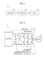
- FIG. 2 is a diagram illustrating a configuration according to the first embodiment.
- FIG. 3 is a graph illustrating relationships among an output power, an output voltage, and an output current of a solar panel according to the first embodiment.
- FIG. 4 is a graph illustrating relationships among a motor rotation speed, electric power, and an output voltage of a solar panel according to the first embodiment.
- FIG. 5 is a flow chart illustrating an operation according to the first embodiment.
- FIG. 6 is a graph illustrating a relationship between a motor rotation speed and electric power in a solar energy utilization system according to a second embodiment of the invention.
- FIG. 7 is a diagram illustrating a configuration of a solar energy utilization system according to a third embodiment of the invention.
- FIG. 8 is a graph illustrating relationships among an output power, an output voltage, and an output current of a solar panel according to the third embodiment.
- FIG. 9 is a diagram illustrating a configuration of a solar energy utilization system according to a fourth embodiment of the invention.
- FIG. 10 is a graph illustrating a relationship between an output power and an output voltage of a solar panel according to the fourth embodiment.
- FIG. 11 is a schematic diagram of a solar energy utilization system according to a fifth embodiment of the invention.
- FIG. 12 is a diagram illustrating a configuration according to the fifth embodiment.
- FIG. 13 is a diagram illustrating a configuration according to another example of the fifth embodiment.
- FIG. 14 is a flow chart illustrating an operation of a solar energy utilization system according to a sixth embodiment of the invention.
- FIG. 15 is a schematic diagram of a solar energy utilization system according to a seventh embodiment of the invention.
- the solar energy utilization system 1 includes a solar panel 10 , an inverter 20 that converts DC power generated by the solar panel 10 to AC power, and a motor 30 driven by the AC power supplied from the inverter 20 .
- the motor 30 serves as a power source for a refrigerator, air-conditioner, pump, or other machines.
- the DC power output by the solar panel 10 is also referred to as a “solar output power”
- an output voltage thereof is also referred to as a “solar output voltage”
- an output current thereof is also referred to as a “solar output current”.
- a solar cell included in the solar panel 10 may be a silicon-based solar cell such as a single crystal silicon solar cell, a polycrystalline silicon solar cell, an amorphous silicon solar cell, or the like, or a compound-based solar cell such as a GaAs solar cell, an InGaAs solar cell, a CdTeCdS-based solar cell, a chalcopyrite-based solar cell, a dye sensitized solar cell, an organic thin-film solar cell, or the like.
- a polycrystalline or amorphous silicon thin-film solar cell it may be preferable to employ a polycrystalline or amorphous silicon thin-film solar cell.
- the solar panel 10 does not necessarily need to be of a flat panel type sealed in glass or the like.
- the solar panel 10 may be formed in a bendable film shape.
- the inverter 20 includes an inverter circuit 21 , which is controlled by a controller 22 .
- the controller 22 may be a controller dedicated to controlling the inverter circuit 21 , or may be a controller responsible for controlling the whole solar energy utilization system 1 .
- the inverter 20 includes, in addition to the inverter circuit 21 functioning as a motor drive circuit, a capacitor 23 connected in parallel to the solar panel 10 , and a solar output voltage monitor 24 functioning as a monitor.
- the solar panel 10 is directly connected to the inverter 20 , and thus it is possible for the solar output voltage monitor 24 , disposed at an input region of the inverter 20 , to directly monitor the output voltage of the solar panel 10 .
- the solar output voltage monitor 24 is also capable of monitoring the input or the output of the inverter circuit 21 functioning as a motor drive circuit.
- the inverter circuit 21 converts the DC power output by the solar panel 10 to AC power with a voltage value that can be utilized by the motor 30 .
- the inverter circuit 21 may be a 2-level or 3-level inverter using a PWM (pulse width modulation) method. Alternatively, a VVVF (variable voltage, variable frequency) control method may be employed. The voltage and the frequency of the AC power output by the inverter circuit 21 are determined so as to adapt to the motor 30 .
- PWM pulse width modulation
- VVVF variable voltage, variable frequency
- the controller 22 has an AD converter function to detect an input voltage of the inverter circuit 21 , that is, the solar output voltage, thereby monitoring the output voltage of the solar panel 10 via the solar output voltage monitor 24 .
- the controller 22 outputs an inverter control signal to the inverter circuit 21 thereby increasing or reducing the rotation speed of the motor 30 .
- the output power of the solar panel 10 is determined based on the power consumption of the motor 30 functioning as a load.
- the motor 30 is an AC induction motor or an AC synchronous motor functioning as an inverter control motor.
- the motor 30 operates with a rotation speed and a torque depending on the output frequency and the output voltage of the AC power output by the inverter circuit 21 .
- the motor 30 may be, for example, a motor operable with a minimum rotation speed of 1,500 rpm, a maximum rotation speed of 5,000 rpm, a maximum consumption power of 150 W, and an operating voltage of 220 V.
- the capacitor 23 smooths the electric power generated by the solar panel 10 .
- the inverter circuit 21 receives electric power and outputs electric power to the motor 30 intermittently by switching.
- the capacitor 23 smooths this electric power such that the solar panel 10 is capable of providing stable low-ripple DC output power.
- FIG. 3 illustrates two graphs respectively shown in upper and low areas of FIG. 3 .
- the upper graph illustrates a general output characteristic of a solar panel in the form of an I-V curve (a curve which is plotted so as to represent a relationship between an output current and an output voltage).
- the lower graph illustrates a general output characteristic of a solar panel in the form of a P-V curve C (a curve which is plotted so as to represent a relationship between an output power and an output voltage).
- the solar output voltage has a maximum value in an open circuit condition (with no load). The solar output voltage decreases with increasing load and increasing output power. The solar output voltage becomes zero in a short circuit condition.
- the solar output power has a maximum value when the output voltage is about 80% of the open circuit voltage.
- An operating point in this situation is referred to as a maximum power point.
- the output voltage at the maximum power point cm on the P-V curve C is denoted as a maximum power point voltage Vmp.
- the motor 30 is controlled as follows.
- the controller 22 controls the inverter circuit 21 using a feedback control method such that when a reduction occurs in electric power (input power) input to the inverter circuit 21 from the solar panel 10 and, as a result, a reduction in the input voltage occurs, an increased current is provided to try to maintain the input power.
- the motor 30 is driven at a voltage above the maximum power point voltage Vmp, even should a reduction in voltage occur, the current will be increased, which will result in an increase in input power, and thus the motor 30 will operate in a stable manner without encountering a lack of electric power.
- the solar output power does not stay constant.
- the maximum power point cm and the maximum power point voltage Vmp vary depending on temperature, an amount of sunlight, and the like. Individual differences in the characteristics among the solar panels 10 and a change in the characteristics with time are factors that lead to variations in the solar output power.
- the driving voltage is to be maintained above the maximum power point voltage Vmp regardless of a change in the solar output power.
- the motor 30 is to be driven such that the difference between the maximum power point voltage Vmp and the output voltage is not very large.
- the controller 22 has a control mode in which the motor drive circuit, that is, the inverter 20 , is controlled such that the output voltage of the solar panel 10 is maintained at a voltage above the maximum power point voltage Vmp.
- this control mode a control is performed so as to change the rotation speed of the motor 30 repeatedly at predetermined timings, and, based on a resultant change in the output of the solar panel 10 , a margin to the maximum power point cm is estimated and the position of the motor operating point is adjusted.
- This control mode makes it possible to correctly detect the margin to the maximum power point voltage Vmp and thus properly drive the motor 30 even if variations occur in the maximum power point voltage Vmp due to factors such as sunlight, temperature, individual differences among the solar panels, and changes in the characteristics with time.
- This control mode is executed when the input voltage of the inverter circuit 21 is equal to or greater than a predetermined value.
- the controller 22 changes the consumption power of the motor 30 by intermittently increasing or reducing the rotation speed of the motor 30 .
- the motor operating point moves on the P-V curve as shown in FIG. 3 , and a change in the solar output voltage occurs, which is detected as ⁇ V by the controller 22 via the solar output voltage monitor 24 .
- ⁇ V the maximum power point voltage
- a maximum allowable value of ⁇ V is determined, and the controller 22 determines whether ⁇ V is smaller than the maximum allowable value. Based on a result of this determination, the controller 22 controls the inverter circuit 21 such that the motor operating point moves along the P-V curve C.
- the controller 22 increases the rotation speed of the motor 30 . As a result, the motor operating point moves in a direction toward the maximum power point cm.
- the controller 22 monitors the change in ⁇ V, and when the margin between the motor operating point and the maximum power point cm decreases down to a predetermined value (a first predetermined value), the controller 22 switches the direction of the change in the rotation speed of the motor 30 from “increasing” to “returning to a previous rotation speed” or “decreasing”.
- the controller 22 reduces the rotation speed of the motor 30 . As a result, the motor operating point moves in a direction away from the maximum power point cm.
- the controller 22 monitors the change in ⁇ V, and when the margin between the motor operating point and the maximum power point cm increases up to a predetermined value (a second predetermined value), the controller 22 switches the direction of the change in the rotation speed of the motor 30 from “decreasing” to “returning to a previous rotation speed” or “increasing”.
- the motor 30 By repeating the operation described above, it is possible to drive the motor 30 within a voltage range in which the voltage is above the maximum power point voltage Vmp and the difference between the maximum power point voltage Vmp and the output voltage is within the predetermined range. This makes it possible to drive the motor 30 in a stable manner, and also makes it possible for the motor 30 to use the output power of the solar panel 10 in a most effective manner.
- the difference between the maximum power point voltage Vmp and the output voltage may be set to a voltage equal to, for example, about 1/15 to 1/10 of the maximum power point voltage Vmp.
- An algorithm of increasing/reducing the rotation speed of the motor 30 may be properly determined such that the above-described conditions are achieved, for example, as follows.
- the rotation speed is increased. If a resultant ⁇ V is smaller than the maximum allowable value, the rotation speed is also increased in a next control step.
- the rotation speed is increased. If a resultant ⁇ V is equal to or greater than the maximum allowable value, the rotation speed is returned to a previous value, and the rotation speed is reduced in a next control step.
- the rotation speed is reduced. If a resultant ⁇ V is smaller than the maximum allowable value, the rotation speed is returned to a previous value, and the rotation speed is increased in a next control step.
- the rotation speed is reduced. If a resultant ⁇ V is equal to or greater than the maximum allowable value, the rotation speed is further reduced repeatedly until ⁇ V becomes smaller than the maximum allowable value. When ⁇ V becomes smaller than the maximum allowable value, the rotation speed is returned to a previous value, and the rotation speed is increased in a next control step.
- the algorithm of increasing or reducing the rotation speed of the motor 30 may be represented as a sequence as shown in FIG. 4 .
- the rotation speed of the motor 30 can be at four levels: that is, “rotation speed level 1 ”, “rotation speed level 2 ”, “rotation speed level 3 ”, and “rotation speed level 4 ”.
- the number of levels may be higher.
- the driving of the motor 30 is started at time t 0 .
- the rotation speed of the motor 30 increases up to rotation speed level 1 in a period from time t 0 to time t 1 .
- the consumption power of the motor 30 increases.
- the solar output power also increases, but the solar output voltage decreases.
- the rotation speed of the motor 30 is maintained at rotation speed level 1 over a period from time t 1 to time t 2 .
- the consumption power of the motor 30 and the solar output voltage also remain at values equal to those at time t 1 .
- the motor 30 has an operation failure and stops. In this case, after a proper time interval has elapsed, the operation is restarted at time t 0 .
- the rotation speed of the motor 30 increases up to rotation speed level 2 .
- the consumption power of the motor 30 increases.
- the solar output power also increases, but the solar output voltage further decreases. There is a large enough margin from the motor operating point to the maximum power point, and the resultant reduction ⁇ V in the solar output voltage is small. If ⁇ V is smaller than the maximum allowable value, the rotation speed of the motor 30 is maintained at rotation speed level 2 over a period from time t 3 to time t 4 .
- the rotation speed of the motor 30 increases up to rotation speed level 3 .
- the consumption power of the motor 30 increases.
- the solar output power also increases, but the solar output voltage decreases. There is a large enough margin from the motor operating point to the maximum power point, and the resultant reduction ⁇ V in the solar output voltage is small. If ⁇ V is smaller than the maximum allowable value, the rotation speed of the motor 30 is maintained at rotation speed level 3 over a period from time t 5 to time t 6 .
- the rotation speed of the motor 30 increases up to rotation speed level 4 .
- the consumption power of the motor 30 increases.
- the solar output power also increases, but the solar output voltage decreases. There is a large enough margin from the motor operating point to the maximum power point, and the resultant reduction ⁇ V in the solar output voltage is small. If ⁇ V is smaller than the maximum allowable value, the rotation speed of the motor 30 is maintained at rotation speed level 4 over a period from time t 7 to time t 8 .
- the controller 22 reduces the rotation speed of the motor 30 down to rotation speed level 3 in a period from time t 8 to time t 9 , and detects ⁇ V. If ⁇ V is smaller than the maximum allowable value, the controller 22 determines that there is a large enough margin from the motor operating point to the maximum power point, and thus, at time t 10 , the controller 22 returns the rotation speed of the motor 30 to a previous level, that is, rotation speed level 4 . The rotation speed level 4 is maintained over a period from time t 10 to time t 11 .
- the controller 22 reduces the rotation speed of the motor 30 down to rotation speed level 3 , and detects ⁇ V. If the resultant ⁇ V is smaller than the maximum allowable value, the controller 22 determines that there is a large enough margin from the motor operating point to the maximum power point, and thus, at time t 13 , the controller 22 returns the rotation speed of the motor 30 to rotation speed level 4 .
- the rotation speed level 4 is maintained over a period from time t 13 to time t 14 .
- the controller 22 reduces the rotation speed of the motor 30 down to rotation speed level 3 and detects ⁇ V.
- the reduction in the amount of sunlight has caused the motor operating point to be close to the maximum power point, and thus a reduction in the rotation speed leads to a large ⁇ V.
- ⁇ V is equal to or greater than the maximum allowable value
- the controller 22 determines that the motor operating point has reached a point close to the maximum power point, and thus, in a period from time t 15 to time t 16 , the controller 22 further reduces the rotation speed of the motor 30 down to rotation speed level 2 . As a result, the motor operating point moves away from the maximum power point.
- ⁇ V is smaller than the maximum allowable value during the period from time t 15 to time t 16 , then in a period from time t 16 to time t 17 the controller 22 returns the rotation speed of the motor 30 to rotation speed level 3 . Over a period from time t 17 to time t 18 , the rotation speed level 3 is maintained.
- the controller 22 reduces the rotation speed of the motor 30 down to rotation speed level 2 and detects ⁇ V. Because the motor operating point is close to the maximum power point, the reduction in the rotation speed leads to a large ⁇ V. If ⁇ V is equal to or greater than the maximum allowable value, the controller 22 determines that the motor operating point has reached a point close to the maximum power point, and thus, in a period from time t 19 to time t 20 , the controller 22 further reduces the rotation speed of the motor 30 down to rotation speed level 1 . As a result, the motor operating point moves away from the maximum power point.
- ⁇ V in the period from time t 19 to time t 20 is smaller than the maximum allowable value, then in a period from time t 20 to time t 21 the controller 22 returns the rotation speed of the motor 30 to rotation speed level 2 .
- the rotation speed is at the rotation speed level 4 , this is the maximum rotation speed, and thus in a next control step, the rotation speed is definitely reduced.
- the rotation speed is at rotation speed level 1 , because rotation speed level 1 is the minimum rotation speed, the rotation speed is definitely increased in a next control step.
- the rotation speed is at rotation speed level 2 or 3 , the determination as to whether the rotation speed is to be increased or reduced is made according to a predetermined algorithm.
- the step width between adjacent levels of the motor rotation speed may be set to 100 to 500 rpm, for example, for a motor with a maximum rotation speed of 5000 rpm.
- ⁇ V may be set to a predetermined fixed value, and the margin to the maximum power point may be estimated based on an amount of increase or reduction, ⁇ RPM, in the rotation speed that can achieve the voltage change ⁇ V.
- ⁇ RPM an amount of increase or reduction
- the input voltage is monitored while continuously increasing (or reducing) the rotation speed.
- the increasing (or reducing) is continued until the input voltage becomes equal to V 1 ⁇ V (or until the input voltage becomes equal to V 1 + ⁇ V).
- FIG. 5 is a flow chart illustrating an operation of the solar energy utilization system 1 .
- step 101 the controller 22 increases the rotation speed of the motor 30 .
- step 102 the controller 22 monitors the solar output voltage and compares it with a previous monitored solar output voltage.
- step 103 the controller 22 determines whether the change ⁇ V in the solar output voltage is large (equal to or greater than a maximum allowable value) or small (less than the maximum allowable value). In a case where it is determined that ⁇ V is large, the processing flow proceeds to step 104 . However, in a case where it is determined that ⁇ V is small, the processing flow returns to step 101 .
- step 104 the controller 22 changes the rotation speed of the motor 30 back to a previous value.
- step 105 the controller 22 monitors the solar output voltage.
- step 106 the controller 22 reduces the rotation speed of the motor 30 .
- step 107 the controller 22 monitors the solar output voltage and compares it with a previous monitored solar output voltage.
- step 108 the controller 22 determines whether the change ⁇ V in the solar output voltage is large (equal to or greater than the maximum allowable value) or small (less than the maximum allowable value). In a case where it is determined that ⁇ V is large, the processing flow returns to step 106 . However, in a case where it is determined that ⁇ V is small, the processing flow proceeds to step 109 .
- step 109 the controller 22 returns the rotation speed of the motor 30 to the previous value.
- step 110 the controller 22 monitors the solar output voltage. Thereafter, the processing flow returns to step 101 .
- FIG. 6 illustrates a solar energy utilization system according to a second embodiment.
- the second embodiment is different from the first embodiment in the sequence of increasing/reducing the rotation speed of the motor 30 .
- the sequence according to the first embodiment described above basically, after the rotation speed of the motor 30 is increased or reduced, the resultant rotation speed is maintained over a proper time period. That is, the rotation speed of the motor 30 is intermittently increased or reduced as a basic structure of the sequence according to the first embodiment above.
- the second embodiment is characterized such that the increasing and reducing of the rotation speed of the motor 30 is performed continuously without intervals of time therebetween, for example, such that a reduction is performed immediately after an increase, or an increase is performed immediately after a reduction, and so on.
- a solar energy utilization system is illustrated in FIG. 7 and FIG. 8 . Also in this third embodiment, like the first and second embodiments, the margin from the motor operating point to the maximum power point is estimated by intermittently or continuously increasing and reducing the rotation speed of the motor 30 . However, instead of the solar output voltage, the solar output current is selected as the measurement parameter.
- the solar energy utilization system 1 includes a solar output current monitor 25 as illustrated in FIG. 7 .
- an input current to the inverter 20 is detected by detecting a voltage drop across a sense resistor in the solar output current monitor 25 .
- the solar panel 10 is connected directly to the inverter 20 , and thus it is possible to directly monitor the output current of the solar panel 10 by monitoring the input current to the inverter 20 .
- the solar output current monitor 25 functioning as the monitor, it is also possible to monitor the input or the output of the inverter circuit 21 functioning as the motor drive circuit.
- a maximum allowable value K for ⁇ I is determined, and the controller 22 determines the relation of the absolute value of ⁇ I and the current with respect to the maximum allowable value K. Based on a result of the determination, the controller 22 controls the inverter circuit 21 such that the motor operating point moves along the P-V curve C.
- the determination and the control by the controller 22 are performed as follows.
- I 1 may be replaced by I 2 , the average value of I 1 and I 2 , or the like.
- the solar output current is directly monitored.
- the output current from the inverter circuit 21 may be monitored to indirectly monitor the solar output current by estimation.
- a solar energy utilization system is illustrated in FIG. 9 and FIG. 10 . Also in the fourth embodiment, as in the previous embodiments, the margin from the motor operating point to the maximum power point is estimated by intermittently or continuously increasing and reducing the rotation speed of the motor 30 . However, the solar output power is selected as the measurement parameter.
- a graph of a P-V curve C of the solar output power shows that the gradient is large at the open circuit voltage Voc, but the gradient decreases as the point approaches the maximum power point cm and the gradient becomes zero at the maximum power point cm.
- the margin from the motor operating point to the maximum power point cm is estimated.
- the solar energy utilization system 1 includes a solar output voltage monitor 24 and a solar output current monitor 25 .
- the solar output voltage monitor 24 and the solar output current monitor 25 functioning as the monitor, it is also possible to monitor the input or the output of the inverter circuit 21 functioning as a motor drive circuit.
- an absolute value ⁇ V
- of the change between the voltages observed before and after the rotation speed of the motor 30 is increased or reduced, and also an absolute value ⁇ P
- of the change between the electric powers observed before and after the rotation speed of the motor 30 is increased or reduced are determined by calculation.
- a maximum allowable value K is determined, and the controller 22 determines the relation of the absolute value of the voltage change and the absolute value of the power change with respect to the maximum allowable value K. Based on a result of this determination, the controller 22 controls the inverter circuit 21 such that the motor operating point moves on the P-V curve C.
- the determination and the control by the controller 22 are performed as follows.
- K ⁇ V> ⁇ P it is determined that there is a large enough margin from the motor operating point to the maximum power point cm, and the rotation speed of the motor 30 is increased.
- the fourth embodiment it is possible to actually trace the P-V curve, and thus it is possible to more reliably estimate the margin to the maximum power point. That is, the consumption power of the motor 30 varies depending on the load even if the rotation speed is the same. The amount of the change in solar output power caused by a change in the rotation speed of the motor 30 is also dependent on the load of the motor 30 . Therefore, even if the same change of the rotation speed were applied to the motor 30 under the same sunlight conditions, it would not necessarily be possible to obtain the same ⁇ V and ⁇ I. Therefore, in the first to third embodiments, the maximum allowable value is to be set while taking into account the variations described above. In contrast, the fourth embodiment is based on the P-V curve itself, and thus no influence is received from the magnitude of the load of the motor 30 . This makes is possible to achieve accurate control, and it becomes possible to effectively use the electric power generated by the solar panel.
- a solar energy utilization system is described in FIG. 11 to FIG. 13 .
- the fifth embodiment is characterized in that a DC-DC converter 40 is disposed between the solar panel 10 and the inverter 20 .
- the DC-DC converter 40 may be, for example, a boost converter. In this case, even when the solar output voltage is lower than a voltage necessary to drive the motor 30 , if the solar output power is sufficient, then the solar output voltage can be increased to the voltage necessary to drive the motor 30 , thereby making it possible to operate the motor 30 .
- the controller 22 controls the rotation speed of the motor 30 as required based on the voltage value at the secondary side of the DC-DC converter 40 , that is, the voltage value at the input region of the inverter 20 .
- a transistor is employed as a rectifier on the secondary side, and the transistor is operated in a complementary manner to the primary side so as to achieve synchronous rectification.
- the transistor is embedded in a photocoupler 41 . This makes it possible for the DC-DC converter 40 to perform a bidirectional power conversion, which makes it possible to prevent the voltage on the secondary side from abnormally increasing even when the inverter 20 stops and an operation occurs with no load. Therefore, it is possible to remove a circuit that feeds back the output voltage of the DC-DC converter 40 to the controller of the DC-DC converter 40 .
- a transformer of the DC-DC converter 40 may include a tertiary winding, which is not shown, and the driving power to the controller 22 may be supplied from the tertiary winding. In this case, it is possible to supply electric power to the controller 22 disposed on the secondary side without having to provide a plurality of transformers, which allows a reduction in cost. Furthermore, even in a state in which the inverter 20 stops and there is no load, it is possible to continue the operation of the DC-DC converter 40 (without encountering an abnormal increase in the voltage on the secondary voltage), and thus it is possible to continue supplying electric power to the controller 22 and allow the controller 22 to continue monitoring the voltage or the like. Therefore, it is possible to continue detecting a failure when the motor 30 is stopped, for example. This makes it possible to achieve a system with a high level of safety.
- the DC-DC converter 40 is connected to a fixed duty supply 42 .
- a fixed duty supplied from the fixed duty supply 42 it is possible to operate the DC-DC converter 40 as a converter that increases or decreases the voltage with a substantially fixed ratio, which makes it possible to achieve simplification of the circuit.
- the DC-DC converter 40 may be formed so as to include a primary side switch 40 a , a transformer 40 b , and a secondary side rectifier 40 c including a MOSFET.
- a control mode in which the inverter circuit 21 is controlled such that the output voltage of the solar panel 10 is maintained at a voltage higher than the maximum power point voltage Vmp by performing the switching of the primary side switch 40 a at a substantially fixed duty and by operating the secondary side rectifier 40 c in a complementary manner to the primary side switch 40 a , it is possible to achieve synchronous rectification.
- the controller 22 is capable of indirectly monitoring the solar output voltage (and current) based on the voltage (and the current) on the secondary side of the DC-DC converter 40 , and is capable of estimating the margin to the maximum power point by increasing and reducing the rotation speed of the motor 30 . This is possible, as described above, because the switching of the switch 40 a on the primary side is performed with a substantially fixed duty, and the secondary side rectifier 40 c is operated in complimentary synchronization with the primary side switch 40 a so as to achieve synchronous rectification.
- the voltage ratio between the primary side and the second side, and also the current ratio are given as a fixed ratio approximately determined by a winding turns ratio of a transformer, and thus it is possible to monitor the state on the primary side, in other words, the output state of the solar panel 10 by monitoring the state on the secondary side. Therefore, when the DC-DC converter 40 is isolated, it is not necessary to go to the lengths of conductively monitoring it, and thus it is possible to achieve simplification of the circuit and a reduction in cost.
- the DC-DC converter 40 may have a configuration other than that illustrated in FIG. 12 .
- a circuit configuration illustrated in FIG. 13 may be employed.
- a push-pull circuit is employed on the primary side, and a full bridge circuit is employed on the secondary side.
- the DC-DC converter 40 is not limited to an isolated type.
- a chopper circuit having a synchronous rectifier function may be used.
- FIG. 14 A solar energy utilization system according to a sixth embodiment is illustrated in FIG. 14 .
- a temperature monitoring function is provided to a device that needs a temperature control, such as a refrigerator, an air-conditioner, or the like. Therefore, although a figure is not given here, the solar energy utilization system according to the sixth embodiment includes the same constituent elements as those included in the first to sixth embodiments.
- the rotation speed of the motor 30 is increased and reduced according to the following algorithm.
- the rotation speed is returned to a previous value in a case where at least one of the following is observed: a temperature higher than the target temperature; and a large ⁇ V (a small margin to the maximum power point). In this case, the rotation speed is reduced in the next control step.
- FIG. 14 is a flow chart illustrating an operation of the solar energy utilization system 1 according to the sixth embodiment.
- step 201 the controller 22 increases the rotation speed of the motor 30 .
- step 202 the controller 22 monitors the temperature (the temperature managed by the solar energy utilization system with respect to the target value).
- step 203 the controller 22 determines whether the temperature is higher or lower than the target temperature. In a case where it is determined that the temperature is higher than the target temperature, the processing flow proceeds to step 206 . In a case where it is determined that the temperature is lower than the target temperature, the processing flow proceeds to step 204 .
- step 204 the controller 22 monitors the solar output voltage and compares it with a previous monitored solar output voltage.
- step 205 the controller 22 determines whether the amount of the change ⁇ V in the solar output voltage is large (equal to or greater than a maximum allowable value) or small (less than the maximum allowable value). In a case where it is determined that ⁇ V is large, the processing flow proceeds to step 206 . However, in a case where it is determined that ⁇ V is small, the processing flow returns to step 201 .
- step 206 the controller 22 returns the rotation speed of the motor 30 to a previous value.
- step 207 the controller 22 monitors the solar output voltage.
- step 208 the controller 22 reduces the rotation speed of the motor 30 .
- step 209 the controller 22 monitors the temperature.
- step 210 the controller 22 determines whether the temperature is higher or lower than the target temperature. In a case where it is determined that the temperature is higher than the target temperature, the processing flow returns to step 208 . In a case where it is determined that the temperature is lower than the target temperature, the processing flow proceeds to step 211 .
- step 211 the controller 22 monitors the solar output voltage and compares it with a previous monitored solar output voltage.
- step 212 the controller 22 determines whether the amount of the change ⁇ V in the solar output voltage is large (equal to or greater than a maximum allowable value) or small (less than the maximum allowable value). In a case where it is determined that ⁇ V is large, the processing flow returns to step 208 . However, in a case where it is determined that ⁇ V is small, the processing flow proceeds to step 213 .
- step 213 the controller 22 returns the rotation speed of the motor 30 to a previous value.
- step 214 the controller 22 monitors the solar output voltage. Thereafter, the processing flow returns to step 201 .
- FIG. 15 A solar energy utilization system according to a seventh embodiment is shown in FIG. 15 .
- the solar panel 10 and a separate power supply 50 such as a battery are both used as the power supply.
- the battery functioning as the separate power supply 50 is connected via a diode 51 to the output region of the solar panel 10 .
- a power supply is used that provides a voltage lower than a maximum power point voltage Vmp of the solar panel 10 .
- the separate power supply 50 is detachably coupled, and the solar energy utilization system 1 can be operated regardless of whether or not the separate power supply 50 is connected.
- the controller 22 monitors the input voltage to the inverter 20 . In a case where it is detected that the voltage at the output region from the solar panel 10 , to which the separate power supply 50 is connected, is equal to or lower than a predetermined value, the controller 22 determines that sufficient electric power is not generated by the solar panel 10 and that electric power is supplied from the separate power supply 50 . The controller 22 then changes the control mode to another particular control mode from that in which the rotation speed of the motor 30 is increased and reduced repeatedly according to predetermined timings as described in the previous embodiments.
- the rotation speed of the motor 30 is maintained at a fixed value such as a minimum rotation speed or the like.
- the controller 22 determines that a sufficient amount of electric power is generated by the solar panel 10 , and the control mode may be preferably returned to the previous mode in which the rotation speed of the motor 30 is increased and reduced repeatedly according to predetermined timings.
- This makes it possible to control the operation such that, in a case where the separate power supply 50 is also used, the motor 30 is controlled at a predetermined rotation speed, and only in a case, in which sufficient electric power is generated by the solar panel 10 , is it possible to extract full power and input it to the motor 30 within a range in which the motor 30 is capable of operating in a stable manner.
- the electric power of the separate power supply 50 from being undesirably consumed while achieving effective usage of the electric power generated by the solar panel 10 .
- the solar output voltage monitor 24 which monitors the output voltage of the solar panel 10 , functions as the monitor.
- the solar output current monitor 25 which monitors the output current of the solar panel 10 , functions as the monitor.
- the solar output voltage monitor 24 that monitors the solar output voltage and the solar output current monitor 25 that monitors the solar output current are provided, and output is monitored by determining the solar power from the solar output voltage and the solar output current. Depending on the situation, it is possible to select any one monitor from among the monitor that monitors the solar output voltage, the monitor that monitors the solar output current, and the monitor that monitors the solar output power.
- the motor 30 As a motor of a refrigerator, an air-conditioner, or a pump, it is possible to realize the solar energy utilization system so as to include a refrigerator, an air-conditioner, or a pump. This makes it possible for the refrigerator, the air-conditioner, or the pump to effectively use the electric power generated by the solar panel 10 . Furthermore, it becomes possible to achieve a stable operation even in a case where the driving is performed only by electric power generated by the solar panel 10 .
- the present invention can be applied to a wide variety of solar energy utilization systems.
Applications Claiming Priority (3)
| Application Number | Priority Date | Filing Date | Title |
|---|---|---|---|
| JP2013-172095 | 2013-08-22 | ||
| JP2013172095 | 2013-08-22 | ||
| PCT/JP2014/060052 WO2015025557A1 (ja) | 2013-08-22 | 2014-04-07 | 太陽光エネルギー利用システム |
Publications (2)
| Publication Number | Publication Date |
|---|---|
| US20160164440A1 US20160164440A1 (en) | 2016-06-09 |
| US9698710B2 true US9698710B2 (en) | 2017-07-04 |
Family
ID=52483346
Family Applications (1)
| Application Number | Title | Priority Date | Filing Date |
|---|---|---|---|
| US14/905,005 Active US9698710B2 (en) | 2013-08-22 | 2014-04-07 | Solar energy utilization system |
Country Status (3)
| Country | Link |
|---|---|
| US (1) | US9698710B2 (ja) |
| JP (1) | JP6105733B2 (ja) |
| WO (1) | WO2015025557A1 (ja) |
Families Citing this family (8)
| Publication number | Priority date | Publication date | Assignee | Title |
|---|---|---|---|---|
| US10931220B2 (en) | 2015-10-13 | 2021-02-23 | Premier Energy Holdings, Inc. | Variable speed maximum power point tracking, solar electric motor controller for induction and permanent magnet AC motors |
| JP2019134498A (ja) * | 2016-05-26 | 2019-08-08 | 日本電産テクノモータ株式会社 | モータの制御装置及び制御方法、並びにポンプシステム |
| JP6338627B2 (ja) * | 2016-09-02 | 2018-06-06 | 株式会社プロセシオ | 太陽電池を電源とした充電回路およびそれを備える意匠パネル |
| US10153691B2 (en) * | 2016-10-07 | 2018-12-11 | Laszlo Keszthelyi | Photovoltaic panel power output booster and method |
| US10488879B2 (en) | 2017-03-09 | 2019-11-26 | Ecole Polytechnique Federale De Lausanne (Epfl) | Device and method for performing maximum power point tracking for photovoltaic devices in presence of hysteresis |
| JP7264023B2 (ja) * | 2019-11-26 | 2023-04-25 | トヨタ自動車株式会社 | ソーラー充電制御装置 |
| US11621666B2 (en) * | 2020-12-31 | 2023-04-04 | Sparq Systems Inc. | Hybrid solar/motor drive inverter |
| JP7312787B2 (ja) * | 2021-06-08 | 2023-07-21 | 本田技研工業株式会社 | 電源システム及び移動体 |
Citations (7)
| Publication number | Priority date | Publication date | Assignee | Title |
|---|---|---|---|---|
| US20020163323A1 (en) * | 2001-03-09 | 2002-11-07 | National Inst. Of Advanced Ind. Science And Tech. | Maximum power point tracking method and device |
| WO2006080112A1 (ja) | 2005-01-31 | 2006-08-03 | Murata Manufacturing Co., Ltd. | 絶縁型dc-dcコンバータ |
| JP2012244652A (ja) | 2011-05-16 | 2012-12-10 | Cosel Co Ltd | スイッチング電源装置 |
| JP2013008206A (ja) | 2011-06-24 | 2013-01-10 | Sharp Corp | モータ駆動装置およびエアコン |
| JP2013097596A (ja) | 2011-11-01 | 2013-05-20 | Sony Corp | 太陽電池システム、電子機器および建築物 |
| JP2013099039A (ja) | 2011-10-28 | 2013-05-20 | Sanyo Denki Co Ltd | 電気機械 |
| JP2013099069A (ja) | 2011-10-31 | 2013-05-20 | Sharp Corp | Dc/dcコンバータ、ソーラー充電システム、及び移動体 |
-
2014
- 2014-04-07 WO PCT/JP2014/060052 patent/WO2015025557A1/ja active Application Filing
- 2014-04-07 JP JP2015532724A patent/JP6105733B2/ja not_active Expired - Fee Related
- 2014-04-07 US US14/905,005 patent/US9698710B2/en active Active
Patent Citations (7)
| Publication number | Priority date | Publication date | Assignee | Title |
|---|---|---|---|---|
| US20020163323A1 (en) * | 2001-03-09 | 2002-11-07 | National Inst. Of Advanced Ind. Science And Tech. | Maximum power point tracking method and device |
| WO2006080112A1 (ja) | 2005-01-31 | 2006-08-03 | Murata Manufacturing Co., Ltd. | 絶縁型dc-dcコンバータ |
| JP2012244652A (ja) | 2011-05-16 | 2012-12-10 | Cosel Co Ltd | スイッチング電源装置 |
| JP2013008206A (ja) | 2011-06-24 | 2013-01-10 | Sharp Corp | モータ駆動装置およびエアコン |
| JP2013099039A (ja) | 2011-10-28 | 2013-05-20 | Sanyo Denki Co Ltd | 電気機械 |
| JP2013099069A (ja) | 2011-10-31 | 2013-05-20 | Sharp Corp | Dc/dcコンバータ、ソーラー充電システム、及び移動体 |
| JP2013097596A (ja) | 2011-11-01 | 2013-05-20 | Sony Corp | 太陽電池システム、電子機器および建築物 |
Non-Patent Citations (2)
| Title |
|---|
| ISA Japanese Patent Office, International Search Report Issued in Application No. PCT/JP2014/060052, Jun. 10, 2014, WIPO, 4 pages. |
| Machine translation JP2013008206A. * |
Also Published As
| Publication number | Publication date |
|---|---|
| JP6105733B2 (ja) | 2017-03-29 |
| JPWO2015025557A1 (ja) | 2017-03-02 |
| US20160164440A1 (en) | 2016-06-09 |
| WO2015025557A1 (ja) | 2015-02-26 |
Similar Documents
| Publication | Publication Date | Title |
|---|---|---|
| US9698710B2 (en) | Solar energy utilization system | |
| RU2480889C1 (ru) | Устройство управления преобразователем | |
| US9985543B1 (en) | Switching power supply | |
| JP4630952B1 (ja) | 直流安定化電源装置 | |
| US9331589B2 (en) | Primary feedback switching power converter controller with intelligent determination of and response to output voltage drops due to dynamic load conditions | |
| US6297617B1 (en) | Battery charger and charge control circuit | |
| US9868358B2 (en) | Power conversion system suppressing reduction in conversion efficiency | |
| WO2011148908A1 (ja) | 太陽電池システム | |
| US20140204634A1 (en) | Power supply apparatus | |
| US9473041B2 (en) | Switching power supply apparatus with improved power conversion efficency to reduce power usage | |
| US11031786B2 (en) | Power convertor, power generation system, and power generation control method | |
| US8711529B2 (en) | Switching apparatus and controlling method thereof | |
| US9484818B2 (en) | DC-DC converter | |
| EP2779250A2 (en) | Photovoltaic bypass and output switching | |
| WO2017043027A1 (ja) | 電力変換装置 | |
| JPWO2019044403A1 (ja) | 太陽光発電システム、パワーコンディショナ | |
| CN110768367A (zh) | 用于磁悬浮轴承控制器供电的装置 | |
| US9780234B2 (en) | Photovoltaic bypass and output switching | |
| JP6296878B2 (ja) | 系統連系インバータおよび発電電力推定方法 | |
| KR20190064828A (ko) | 전력변환장치 및 그의 동작 방법 | |
| JP5238447B2 (ja) | Dc−dcコンバータ | |
| EP4340195A1 (en) | Power converter controller, power converter and method of operating a power converter | |
| JP2015154517A (ja) | Pvパワーコンディショナ | |
| US11387743B2 (en) | Power supply device and control method for stably operating a device when a frequency of an input power supply fluctuates | |
| JP5721669B2 (ja) | 電力変換装置および冷凍空調システム |
Legal Events
| Date | Code | Title | Description |
|---|---|---|---|
| AS | Assignment |
Owner name: SHARP KABUSHIKI KAISHA, JAPAN Free format text: ASSIGNMENT OF ASSIGNORS INTEREST;ASSIGNORS:KATAOKA, KOHTAROH;NOMURA, MASARU;WAKAIKI, SHUJI;AND OTHERS;SIGNING DATES FROM 20151215 TO 20151218;REEL/FRAME:037489/0457 |
|
| STCF | Information on status: patent grant |
Free format text: PATENTED CASE |
|
| CC | Certificate of correction | ||
| MAFP | Maintenance fee payment |
Free format text: PAYMENT OF MAINTENANCE FEE, 4TH YEAR, LARGE ENTITY (ORIGINAL EVENT CODE: M1551); ENTITY STATUS OF PATENT OWNER: LARGE ENTITY Year of fee payment: 4 |