US9698610B2 - Charge and discharge control method, charge and discharge control system, and charge and discharge control apparatus - Google Patents
Charge and discharge control method, charge and discharge control system, and charge and discharge control apparatus Download PDFInfo
- Publication number
- US9698610B2 US9698610B2 US14/372,032 US201314372032A US9698610B2 US 9698610 B2 US9698610 B2 US 9698610B2 US 201314372032 A US201314372032 A US 201314372032A US 9698610 B2 US9698610 B2 US 9698610B2
- Authority
- US
- United States
- Prior art keywords
- power
- instruction value
- value
- charge
- soc
- Prior art date
- Legal status (The legal status is an assumption and is not a legal conclusion. Google has not performed a legal analysis and makes no representation as to the accuracy of the status listed.)
- Active, expires
Links
- 238000000034 method Methods 0.000 title claims abstract description 191
- 230000006641 stabilisation Effects 0.000 claims description 38
- 238000011105 stabilization Methods 0.000 claims description 38
- 230000007423 decrease Effects 0.000 claims description 33
- 230000004043 responsiveness Effects 0.000 claims description 7
- 238000004891 communication Methods 0.000 claims description 4
- 238000012937 correction Methods 0.000 description 188
- 238000004364 calculation method Methods 0.000 description 56
- 238000010586 diagram Methods 0.000 description 24
- 230000006870 function Effects 0.000 description 20
- 230000008859 change Effects 0.000 description 18
- 238000004590 computer program Methods 0.000 description 17
- 238000012986 modification Methods 0.000 description 16
- 230000004048 modification Effects 0.000 description 16
- 230000015556 catabolic process Effects 0.000 description 13
- 238000006731 degradation reaction Methods 0.000 description 13
- 230000033228 biological regulation Effects 0.000 description 10
- 238000011156 evaluation Methods 0.000 description 8
- 230000007774 longterm Effects 0.000 description 5
- 230000000087 stabilizing effect Effects 0.000 description 5
- 238000006243 chemical reaction Methods 0.000 description 4
- 239000000470 constituent Substances 0.000 description 3
- 230000003247 decreasing effect Effects 0.000 description 3
- 230000000593 degrading effect Effects 0.000 description 3
- 238000007599 discharging Methods 0.000 description 3
- 238000010248 power generation Methods 0.000 description 2
- 230000008569 process Effects 0.000 description 2
- 230000009467 reduction Effects 0.000 description 2
- HBBGRARXTFLTSG-UHFFFAOYSA-N Lithium ion Chemical compound [Li+] HBBGRARXTFLTSG-UHFFFAOYSA-N 0.000 description 1
- 230000005540 biological transmission Effects 0.000 description 1
- 239000003990 capacitor Substances 0.000 description 1
- 238000005314 correlation function Methods 0.000 description 1
- 238000013461 design Methods 0.000 description 1
- 230000000694 effects Effects 0.000 description 1
- 230000005611 electricity Effects 0.000 description 1
- 230000010354 integration Effects 0.000 description 1
- 229910001416 lithium ion Inorganic materials 0.000 description 1
- 239000000463 material Substances 0.000 description 1
- 230000007246 mechanism Effects 0.000 description 1
- 238000012545 processing Methods 0.000 description 1
- 238000005070 sampling Methods 0.000 description 1
- 238000010187 selection method Methods 0.000 description 1
- 239000004065 semiconductor Substances 0.000 description 1
Images


Classifications
-
- H—ELECTRICITY
- H02—GENERATION; CONVERSION OR DISTRIBUTION OF ELECTRIC POWER
- H02J—CIRCUIT ARRANGEMENTS OR SYSTEMS FOR SUPPLYING OR DISTRIBUTING ELECTRIC POWER; SYSTEMS FOR STORING ELECTRIC ENERGY
- H02J7/00—Circuit arrangements for charging or depolarising batteries or for supplying loads from batteries
- H02J7/02—Circuit arrangements for charging or depolarising batteries or for supplying loads from batteries for charging batteries from ac mains by converters
- H02J7/04—Regulation of charging current or voltage
-
- H—ELECTRICITY
- H02—GENERATION; CONVERSION OR DISTRIBUTION OF ELECTRIC POWER
- H02J—CIRCUIT ARRANGEMENTS OR SYSTEMS FOR SUPPLYING OR DISTRIBUTING ELECTRIC POWER; SYSTEMS FOR STORING ELECTRIC ENERGY
- H02J7/00—Circuit arrangements for charging or depolarising batteries or for supplying loads from batteries
-
- H—ELECTRICITY
- H02—GENERATION; CONVERSION OR DISTRIBUTION OF ELECTRIC POWER
- H02J—CIRCUIT ARRANGEMENTS OR SYSTEMS FOR SUPPLYING OR DISTRIBUTING ELECTRIC POWER; SYSTEMS FOR STORING ELECTRIC ENERGY
- H02J3/00—Circuit arrangements for ac mains or ac distribution networks
- H02J3/28—Arrangements for balancing of the load in a network by storage of energy
- H02J3/32—Arrangements for balancing of the load in a network by storage of energy using batteries with converting means
-
- H—ELECTRICITY
- H02—GENERATION; CONVERSION OR DISTRIBUTION OF ELECTRIC POWER
- H02J—CIRCUIT ARRANGEMENTS OR SYSTEMS FOR SUPPLYING OR DISTRIBUTING ELECTRIC POWER; SYSTEMS FOR STORING ELECTRIC ENERGY
- H02J7/00—Circuit arrangements for charging or depolarising batteries or for supplying loads from batteries
- H02J7/007—Regulation of charging or discharging current or voltage
- H02J7/00712—Regulation of charging or discharging current or voltage the cycle being controlled or terminated in response to electric parameters
- H02J7/007182—Regulation of charging or discharging current or voltage the cycle being controlled or terminated in response to electric parameters in response to battery voltage
-
- H02J7/045—
Definitions
- the present invention relates to a charge or discharge control method of a power storage apparatus to be used in stabilization control of a grid.
- frequency regulation which keeps the frequency of the grid within a predetermined range is known.
- the frequency regulation is a control method of keeping the frequency of the grid within a predetermined range by increasing the output of a power generator which provides power to the power system when the frequency of the grid is lower than the reference frequency, and by decreasing the output of a power generator which provides power to the power system when the frequency of the grid is higher than the reference frequency.
- a method is performed in which the power system operator calculates a power instruction for frequency regulation and the power service provider performs frequency regulation by controlling the output of the power generator based on the instruction.
- the power storage apparatus discharges from the power storage apparatus to the grid when the frequency of the grid decreases, and charges from the grid to the power storage apparatus when the frequency of the grid increases.
- a power value of the power to be charged and discharged by the power storage apparatus is determined by a power instruction value which is transmitted from the power system operator to the power storage apparatus in a period of several seconds, and the power instruction value is determined by the power system operator.
- the power storage apparatus needs to previously store electricity in order to discharge according to the power instruction value.
- the power storage apparatus needs to previously secure an electric storage capacity in order to charge according to the power instruction value.
- the state of charge (SOC) after the end of the frequency regulation should almost match with the SOC at the start of the frequency regulation.
- SOC state of charge
- a discharge amount of the power storage apparatus is larger than a charge amount of the power storage apparatus over a medium to long-term period.
- the SOC decreases as time passes. This means that the power storage apparatus is not able to continue charge or discharge.
- the present invention solves the above described problem, and provides a charge or discharge control method which makes it possible to secure responsiveness of the output of the power storage apparatus to the power instruction value, and control the SOC of the power storage apparatus.
- a charge or discharge control method for performing stabilization control of a grid by causing a power storage apparatus connected to the grid to charge or discharge, the charge or discharge control method including: receiving, in a period of the stabilization control, a power instruction value indicating a power value of power which the power storage apparatus is to charge or discharge; obtaining a remaining state of charge (SOC) of the power storage apparatus; obtaining a target SOC which is a target value of the SOC of the power storage apparatus; and controlling charge or discharge of the power storage apparatus according to the power instruction value, when the power instruction value is received, wherein, in the controlling, where a delay time from when the power instruction value is received to when the power storage apparatus is caused to charge or discharge according to the power instruction value is determined according to a difference between the target SOC and the remaining SOC, (i) when the remaining SOC is smaller than the target SOC, the delay time is set, in a period in which the power instruction
- FIG. 1 is a diagram illustrating an example of a change of the SOC of the power storage apparatus in a stabilization control period.
- FIG. 2 is a diagram illustrating a correction method of a power instruction value illustrated in Patent Literature 1.
- FIG. 3 is a diagram illustrating an outline of a charge or discharge control apparatus according to an embodiment.
- FIG. 4 is a diagram illustrating an example of the power instruction value.
- FIG. 5 is a block diagram illustrating a configuration of a charge or discharge control apparatus according to an embodiment.
- FIG. 6 is a flowchart illustrating an operation of the charge or discharge control apparatus.
- FIG. 7 is a flowchart illustrating an operation of a corrected power amount calculation unit.
- FIG. 8 is a diagram illustrating an example of a planned SOC and an actual SOC.
- FIG. 9 is a flowchart illustrating an operation of a correction method selection unit.
- FIG. 10 is a flowchart illustrating an operation of a parameter determination unit.
- FIG. 11 is a flowchart illustrating an operation of a power instruction value correction unit.
- FIG. 12 is a diagram illustrating a relationship between the power instruction value and the corrected instruction value when the corrected power value is a positive value and the first correction method is used.
- FIG. 13 is a diagram illustrating a relationship between the power instruction value and the corrected instruction value when the corrected power value is a negative value and the first correction method is used.
- FIG. 14 is a diagram illustrating a relationship between the power instruction value and the corrected instruction value when the corrected power value is a positive value and the first correction method according to Modification 2 is used.
- FIG. 15 is a diagram illustrating a relationship between the power instruction value and the corrected instruction value when the corrected power value is a positive value and the first correction method according to Modification 3 is used.
- FIG. 16 is a diagram illustrating a relationship between the power instruction value and the corrected instruction value when the corrected power value is a positive value and the second correction method is used.
- FIG. 17 is a diagram illustrating a relationship between the power instruction value and the corrected instruction value when the corrected power value is a positive value and the third correction method is used.
- FIG. 18 is a diagram illustrating a relationship between the power instruction value and the corrected instruction value when the corrected power value is a positive value and the fourth correction method is used.
- FIG. 1 is a diagram illustrating an example of a change of the SOC of the power storage apparatus in a stabilization control period (frequency regulation period).
- a vertical axis denotes the SOC
- a horizontal axis denotes time.
- Patent Literature 1 discloses a method of maintaining the SOC of the power storage apparatus by correcting the power instruction value (output instruction value) using a charge or discharge efficiency value, by discharging power less than a power value indicating the power instruction value when the power storage apparatus discharges, and by charging power more than a power value indicating the power instruction value when the power storage apparatus charges.
- FIG. 2 is a diagram illustrating a correction method of a power instruction value illustrated in Patent Literature 1.
- the output quality is quantitatively calculated by the power system operator as a performance score.
- the performance score is evaluated based on a weighted sum of each of the three evaluation values of “degree of delay”, “degree of correlation”, and “degree of precision” of a power value of power actually outputted from the power storage apparatus with respect to the power instruction value.
- the “degree of delay” indicates a delay
- the “degree of correlation” indicates a similarity of waveforms
- the “degree of precision” indicates a degree of similarity of the size of output.
- Patent Literature 1 the object of a method of correcting a power value using an efficiency value of charge or discharge illustrated in Patent Literature 1 is to maintain the SOC.
- the SOC control having a high degree of precision which increases or decreases the SOC by an arbitrary amount cannot be realized.
- the performance score indicates a higher contribution to stabilization of the grid when the value of the performance score is higher.
- a calculation method of the performance score is different for each of the power system operators.
- the calculation method of the performance score is changed depending on a change in the situation of the grid.
- a charge or discharge control method for controlling charge or discharge of a power storage apparatus connected to a grid in a stabilization control period for stabilizing power of the grid, the charge or discharge control method including: receiving, in the stabilization control period, a power instruction value indicating a power value of power which the power storage apparatus is to charge or discharge; obtaining a remaining state of charge (SOC) of the power storage apparatus, and a target SOC which is a target value of the SOC of the power storage apparatus; and controlling charge or discharge of the power storage apparatus according to the power instruction value, when the power instruction value is received, wherein, in the controlling, where a delay time is determined according to a difference between the target SOC and the remaining SOC, the power instruction value indicating discharge of the power storage apparatus is a positive value, and the power instruction value indicating charge of the power storage apparatus is a negative value, (i) when the remaining SOC is smaller than the target SOC, control is performed
- the charge or discharge control method it is possible to control the SOC of the power storage apparatus while reducing degradation of a “degree of correlation” and a “degree of precision” in the performance score.
- the delay time is determined to be a longer time as the difference between the target SOC and the remaining SOC is larger.
- the delay time is determined to be a shorter time as a difference is larger between a first power value and a second power value received earlier than the first power value, and then control is performed to cause the power storage apparatus to charge or discharge according to the first power instruction value at a timing when the delay time passes after the first power instruction value is received.
- a predicted instruction value which predicts a future power instruction value is calculated using history of the power instruction value previously received, and (i) when the remaining SOC is smaller than the target SOC, control is performed to cause the power storage apparatus to charge or discharge according to the predicted instruction value corresponding to the power instruction value, in a period in which the predicted instruction value corresponding to the power instruction value increases as time passes, at a timing when the delay time passes after the power instruction value is received, and control is performed to cause the power storage apparatus to charge or discharge according to the predicted instruction value corresponding to the power instruction value, in a period in which the predicted instruction value corresponding to the power instruction value decreases as time passes, at a timing which precedes, by the delay time, from when the power instruction value is received, and (ii) when the remaining SOC is larger than the target SOC, control is performed to cause the power storage apparatus to charge or discharge according to the predicted instruction value corresponding to the power instruction value, in a period in which the predicted instruction value corresponding to the power instruction value decreases as
- the remaining SOC is obtained in a predetermined period
- the target SOC is a target value of the SOC after passage of predetermined time from a timing when the remaining SOC is obtained.
- the delay time is determined to be a time which is shorter than predetermined upper limit of time.
- the delay time includes a time from when the power instruction value is received to when the charge or discharge of the power storage apparatus is started according to the power instruction value.
- a charge or discharge control method includes is a charge or discharge control method for controlling charge or discharge of a power storage apparatus connected to a grid in a stabilization control period for stabilizing power of the grid, the charge or discharge control method including: receiving, in the stabilization control period, a power instruction value indicating a power value of power which the power storage apparatus is to charge or discharge; obtaining a remaining state of charge (SOC) of the power storage apparatus, and a target SOC which is a target value of the SOC of the power storage apparatus; and (i) determining, when the remaining SOC is smaller than the target SOC, a first offset power value which is a power value which indicates charge and has an absolute value which is larger when the absolute value of the power value indicated by the power instruction value is smaller, and causing the power storage apparatus to charge or discharge power of a power value obtained by adding the first offset power value and the power value indicated by the power instruction value, and (ii) determining, when the remaining SOC is larger than the target SOC
- the charge or discharge control method it is possible to control the SOC of the power storage apparatus while reducing degradation of a “degree of correlation” in the performance score.
- a charge or discharge control method for controlling charge or discharge of a power storage apparatus connected to a grid in a stabilization control period for stabilizing power of the grid, the charge or discharge control method including: receiving, in the stabilization control period, a power instruction value indicating a power value of power which the power storage apparatus is to charge or discharge; obtaining a remaining state of charge (SOC) of the power storage apparatus, and a target SOC which is a target value of the SOC of the power storage apparatus; determining predetermined time according to a difference between the target SOC and the remaining SOC, (i) stopping charge or discharge of the power storage apparatus for the predetermined time in every predetermined period, when the remaining SOC is smaller than the target SOC, in a period in which the power instruction value indicates discharge, and (ii) stopping charge or discharge of the power storage apparatus for the predetermined time in every predetermined period, when the remaining SOC is larger than the target SOC, in a period in which the power instruction
- the charge or discharge control method it is possible to control the SOC of the power storage apparatus while reducing degradation of a “degree of precision” in the performance score.
- a charge or discharge control method for controlling charge or discharge of a power storage apparatus connected to a grid in a stabilization control period for stabilizing power of the grid, the charge or discharge control method including: receiving, in the stabilization control period, a power instruction value indicating a power value of power which the power storage apparatus is to charge or discharge; obtaining a remaining state of charge (SOC) of the power storage apparatus, and a target SOC which is a target value of the SOC of the power storage apparatus; and (i) determining a first offset power value which is a power value which indicates charge and is smaller when the power value indicating the power instruction value is larger, when the remaining SOC is smaller than the target SOC, and causing the power storage apparatus to charge or discharge power of a power value obtained by adding the first offset power value and the power value indicated by the power instruction value, (ii) determining a second offset power value which indicates discharge and is larger when the power value indicated by the power instruction value is smaller,
- the charge or discharge control method it is possible to control the SOC of the power storage apparatus while reducing degradation of a “degree of correlation” in the performance score.
- a charge or discharge control method for controlling charge or discharge of a power storage apparatus connected to a grid in a stabilization control period for stabilizing power of the grid, based on a performance score indicating responsiveness of the charge or discharge to a power instruction value
- the charge or discharge control method including: receiving, in the stabilization control period, a power instruction value indicating a power value of power which the power storage apparatus is to charge or discharge; obtaining a remaining state of charge (SOC) of the power storage apparatus, and a target SOC which is a target value of the SOC of the power storage apparatus; and controlling charge or discharge of the power storage apparatus according to the power instruction value, when the power instruction value is received,
- the performance score is represented by a weighted sum of each of a degree of delay, a degree of correlation, and a degree of precision, the each of the degree of delay, the degree of correlation, and the degree of precision being between a power value indicated by the power instruction value and a
- the charge or discharge control method it is possible to appropriately correct the power instruction value based on the calculation method of the performance score.
- FIG. 3 is a diagram illustrating an outline of a charge or discharge control apparatus according to Embodiment 1.
- a charge or discharge control apparatus 100 is an apparatus which, in a predetermined stabilization control period, controls charge or discharge of a grid 130 of a power storage apparatus 120 , by receiving a power instruction value outputted from a power instruction apparatus 110 and by outputting a power instruction value after correction to the power storage apparatus 120 .
- the stabilization control period is described as a configuration of a plurality of steps by setting a 10-minute period as a step.
- the charge or discharge control apparatus 100 performs charge or discharge of the power storage apparatus 120 which follows the power instruction value in organic collaboration with the power storage apparatus 120 , and controls the SOC of the power storage apparatus 120 .
- the charge or discharge control apparatus 100 and the power storage apparatus 120 constitute an electric storage control system.
- the power storage apparatus 120 is an apparatus which has a capability of storing and releasing electric energy, and specifically includes a secondary battery such as a lead storage battery, a lithium-ion battery, a redox flow battery, and a fly wheel, and a pumped-storage power generator.
- a secondary battery such as a lead storage battery, a lithium-ion battery, a redox flow battery, and a fly wheel, and a pumped-storage power generator.
- the power instruction apparatus 110 is an apparatus owned by a power system operator, and transmits a power instruction value to the charge or discharge control apparatus 100 in order to control a frequency of the grid 130 within a certain range.
- the charge or discharge control apparatus 100 can be realized not only by a microprocessor, a digital signal processor (DSP), and a system LSI, but also by a server and a cloud on the Internet.
- DSP digital signal processor
- system LSI system LSI
- FIG. 4 is a diagram illustrating an example of the power instruction value.
- a horizontal axis denotes time
- a vertical axis denotes a power instruction value.
- the power instruction value is a power value of power that the power storage apparatus 120 needs to charge or discharge according to the power instruction value.
- the power instruction value is an instruction value which instructs the power storage apparatus 120 to discharge when the power instruction value is a positive value (+), and instructs the power storage apparatus 120 to charge when the power instruction value is a negative value ( ⁇ ).
- the absolute value of the power instruction value is larger, the power storage apparatus 120 performs more charge or discharge.
- the power storage apparatus 120 can output power within a range of ⁇ 1.0 MW.
- the upper limit value of the power instruction value is +1.0 MW
- the lower limit value of the power instruction value is ⁇ 1.0 MW.
- the power instruction value is transmitted to the charge or discharge control apparatus 100 in a period of several seconds, that is, a period of 2 seconds.
- the power instruction value in the stabilization control largely changes in a short time because the power instruction value depends on a change of deviation of the frequency of the grid 130 .
- the power instruction value does not deviate in one direction. Therefore, the average of the power instruction value in a long term tends to be ⁇ 0.
- the power instruction value may indicate a ratio to the largest value of the output of the power storage apparatus 120 ( ⁇ 1.0 MW, hereinafter also referred to as control capability), instead of as the power value itself.
- control capability the power value of power that the power storage apparatus 120 charges and discharges according to the power instruction value is (control capability) ⁇ (ratio indicated by power instruction value).
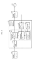
- FIG. 5 is a block diagram illustrating a configuration of the charge or discharge control apparatus 100 according to Embodiment 1. It should be noted that in FIG. 5 , the same reference signs are assigned to the same structural elements as those in FIG. 3 , and a description thereof will be omitted.
- the charge or discharge control apparatus 100 includes a receiving unit 101 , a corrected power amount calculation unit 102 , a control unit 103 , and a storage unit 104 .
- the receiving unit 101 receives a power instruction value in every predetermined period in the stabilization control period. In the present embodiment, the receiving unit 101 receives a power instruction value in every period of 2 seconds. It should be noted that in the present embodiment, the power instruction value is transmitted from the power instruction apparatus 110 . However, the charge or discharge control apparatus 100 may determine the power instruction value. For example, the charge or discharge control apparatus 100 may further include a power instruction value determination unit which measures a frequency of AC current of the grid 130 and determines the power instruction value according to the measured frequency, and the receiving unit 101 may receive the power instruction value determined by the power instruction value determination unit.
- the corrected power amount calculation unit 102 obtains information about the SOC of the power storage apparatus 120 and information about a target SOC which is a target value of the SOC of the power storage apparatus 120 , and then calculates a corrected power amount.
- the SOC is, for example, represented by a percentage.
- the storage unit 104 stores a calculation formula of the performance score to be described later.
- Information about the calculation formula of the performance score stored in the storage unit 104 may be stored outside the charge or discharge control apparatus 100 , such as a cloud on the Internet. In other words, the storage unit 104 is not an indispensable structural element.
- the calculation formula of the performance score PS stored in the storage unit 104 is updated when initializing in introducing a charge or discharge control system using the charge or discharge control apparatus 100 and when changing a contract of the performance score calculation formula of the power system operator.
- the control unit 103 performs control of causing the power storage apparatus 120 to charge or discharge power of a power value indicated by the power instruction value every time the receiving unit 101 receives the power instruction value. In other words, the control unit 103 performs control of causing the power storage apparatus 120 to charge or discharge power of a power value indicated by the power instruction value when the receiving unit 101 receives the power instruction value.
- “when the receiving unit 101 receives the power instruction value” means a predetermined timing including a delay time which is inevitably generated from when the receiving unit 101 receives the power instruction value to when the receiving unit 101 causes the power storage apparatus 120 to charge or discharge according to the power instruction value.
- the control unit 103 includes a correction method selection unit 105 , a parameter determination unit 106 , and a power instruction value correction unit 107 .
- the correction method selection unit 105 selects a correction method of the power instruction method based on the performance score calculation formula to quantitatively calculate the output quality of the power storage apparatus 120 .
- the parameter determination unit 106 determines a corrected parameter to correct the power instruction value, based on the corrected power amount calculated by the corrected power amount calculation unit 102 and the correction method selected by the correction method selection unit 105 .
- the power instruction value correction unit 107 corrects the power instruction value that the receiving unit 101 obtains from the power instruction apparatus 110 , and then outputs the corrected instruction value to the power storage apparatus 120 .
- the performance score is a value which quantitatively indicates the output quality of the power storage apparatus 120 with respect to the power instruction value.
- the performance score PS is represented by Expression (1) using the three evaluation values D, A, and P.
- D denotes a degree of delay which indicates a degree of delay of the output value of the power storage apparatus 120 (power value of power actually outputted from the power storage apparatus 120 ) to the power instruction value
- A denotes a degree of correlation which indicates a degree of correlation between the power instruction value and the output value of the power storage apparatus 120
- P denotes a degree of precision which depends on the error between the power instruction value and the output value of the power storage apparatus 120 .
- k i is a weight coefficient of each of the evaluation values, and is a real number which satisfies Expression (2) and is no less than 0.
- the degree of delay D is calculated using Expression (3) where ⁇ represents a delay time of the power storage apparatus 120 with respect to the power instruction value of the power storage apparatus 120 , and T represents an assumed longest delay time.
- T is 5 [min].
- the delay time ⁇ is a time difference between the waveforms when the waveform of the power instruction value and the waveform of the output value of the power storage apparatus 120 are gradually moved and then the degree of correlation between the two becomes the largest.
- the degree of correlation A is calculated using a correlation function y and Expression (4).
- r denotes the power instruction value
- y t- ⁇ is a value obtained by extending the output value of the power storage apparatus 120 back by the delay time ⁇ and then performing a parallel shift. In other words, an influence of the delay time ⁇ is removed from the degree of correlation A.
- the degree of precision P is calculated using Expression (5).
- the degree of precision P is a value obtained by subtracting the error rate of the power instruction value and the output value of the power storage apparatus 120 from 1.
- Each of the degree of delay, the degree of correlation, and the degree of precision takes a value from 0.0 to 1.0, and indicates that the output quality is better when the value is closer to 1.0.
- the performance score PS also takes a value from 0.0 to 1.0, and indicates that the output quality is better when the value is closer to 1.0.
- the weight coefficient k i of each of the evaluation values is different depending on the grid 130 which is the target of the stabilization control, and the weight coefficient k i is determined by the power system operator. It should be noted that in the present embodiment, as described above, the performance score PS having the value of the weight coefficient k i which is a parameter will be described.
- the calculation formula of the performance score PS is not limited to Expression (1), and may be another calculation formula.
- FIG. 6 is a flowchart illustrating the operation of the charge or discharge control apparatus 100 .
- the receiving unit 101 receives the power instruction value (S 001 ).
- the corrected power amount calculation unit 102 obtains the remaining SOC of the power storage apparatus 120 , and the target SOC of the power storage apparatus 120 (S 002 ). More specifically, the corrected power amount calculation unit 102 calculates the corrected power amount from a difference between the remaining SOC (actual SOC) and the target SOC (predetermined SOC).
- control unit 103 (correction method selection unit 105 ) selects a selection method of the power instruction value based on the performance score calculation formula (S 003 ).
- control unit 103 corrects the power instruction value according to the selected correction method, and then outputs the corrected instruction value to the power storage apparatus 120 (S 004 ).
- the corrected power amount calculation unit 102 calculates, in order to control the SOC of the power storage apparatus 120 , a corrected power amount from a difference between the actual SOC of the power storage apparatus 120 and the predetermined SOC (target SOC).
- the predetermined SOC is a certain SOC, or the SOC (planned SOC) which is planned by the operator of the electric storage control system and changes depending on time.
- the corrected power amount calculation unit 102 calculates a corrected power amount from a difference between the actual SOC of the power storage apparatus 120 and the target SOC of the power storage apparatus 120 .
- the corrected power amount is a power amount indicating how much more (or less) power of a power value that the power storage apparatus 120 should charge or discharge compared with the power value indicated by the power instruction value in one step.
- the corrected power amount calculation unit 102 calculates the corrected power amount at a frequency of about once in one step in the stabilization control period. However, the corrected power amount calculation unit 102 may calculate the corrected power amount at a frequency of less than once in one step.
- the stabilization control period is composed of Step 1, Step 2, . . . Step n that are successive, by setting a period of 10 minutes as one step.
- FIG. 7 is a flowchart illustrating an operation of the corrected power amount calculation unit 102 .
- the corrected power amount calculation unit 102 calculates, using Expression (6), calculates the corrected power amount in the step based on the difference between the planned SOC and the actual SOC obtained from the power storage apparatus 120 (S 101 ).
- x n denotes the corrected power amount in Step n
- C n denotes a planned SOC
- C n denotes the SOC in the step
- T c denotes the time of one step
- T e denotes predetermined time set to correct the difference.
- T c is 10 minutes
- T e is 60 minutes.
- FIG. 8 is a diagram illustrating an example of a planned SOC and an actual SOC.
- the corrected power amount calculation unit 102 corrects again the corrected power value x n calculated by Expression (6), using Expression (7) (S 102 ).
- L is a power amount which corresponds to the one step of average power loss (conversion loss power amount) which is generated when the power storage apparatus 120 charges and discharges to the grid 130 . It should be noted that the corrected power amount calculation unit 102 does not have to add the conversion loss power amount in Step S 102 .
- the corrected power amount calculation unit 102 outputs, to the parameter determination unit 106 , the corrected power amount x n which is calculated using Expression (6) (and Expression (7)) (S 103 ).
- the correction method selection unit 105 selects a correction method of the power instruction value based on the performance score PS calculation formula stored in the storage unit 104 .
- the correction method selection unit 105 selects the correction method of the power instruction unit based on the weight coefficient k i of each evaluation value which is part of the calculation formula.
- the correction method selection unit 105 selects one of the correction methods from the first correction method (correction method M 1 ) which prioritizes the degree of correlation A and the degree of accuracy P, the second correction method which prioritizes the degree of correlation A (correction method M 2 ), and the third correction method which prioritizes the degree of precision P (correction method M 3 ).
- Embodiment 1 will mainly describe the correction method M 1 in detail, and Embodiment 2 and Embodiment 3 will describe the correction method M 2 and the correction method M 3 , respectively.
- FIG. 9 is a flowchart illustrating the operation of the correction method selection unit 105 .
- the correction method selection unit 105 obtains, from the storage unit 104 , the weight coefficient k i of each evaluation value of the performance score calculation formula (S 201 ).
- the correction method selection unit 105 determines the correction method of the power instruction value using a discriminant function which sets each weight coefficient as a variable (S 202 ).
- the discriminant function is a function obtained by linear combination of (i) the weight coefficient k i which is a variable in the discriminant function and (ii) a linear discriminant function.
- the discriminant function is obtained by a discriminant analysis.
- the correction method selection unit 108 selects the correction method m from the correction method candidate M i , using positive and negative of the sign of the discriminant function f Li .
- the correction method selection unit 105 uses the following three discriminant functions as the discriminant function f Li .
- ⁇ L1 ⁇ 2 k 1 +k 2 +k 3 Expression (9)
- ⁇ L2 ⁇ k 1 +2 k 2 ⁇ k 3 Expression (10)
- ⁇ L3 ⁇ k 1 ⁇ k 2 +2 k 3 Expression (11)
- k 1 denotes the weight coefficient to be multiplied by the degree of delay D
- k 2 denotes the weight coefficient to be multiplied by the degree of correlation A
- k 3 denotes the weight coefficient to be multiplied by the degree of precision P.
- the correction method selection unit 105 selects the correction method M 1 .
- the correction method selection unit 105 selects the correction method M 2 .
- the discriminant function f L3 illustrated in Expression (11) satisfies a condition illustrated in Expression (8), that is, when the weight coefficient k 3 of the degree of precision P is larger than the other weight coefficients
- the correction method selection unit 105 selects the correction method M 3 .
- the correction method selection unit 105 selects a correction method in which the value of the discriminant function returns the largest value.
- the correction method selection unit 105 outputs the selected correction method m to the parameter determination unit 106 (S 203 ).
- the charge or discharge control apparatus 100 can secure responsiveness of the output of the power storage apparatus 120 to the power instruction value and can control the SOC of the power storage apparatus 120 , by changing the correction method m of the power instruction value corresponding to the performance score PS calculation formula.
- the parameter determination unit 106 determines a corrected parameter to correct the power instruction value, using the corrected power amount x n calculated by the corrected power amount calculation unit 102 and the correction method m selected by the correction method selection unit 105 . It should be noted that the corrected parameter is different depending on the correction method m selected by the correction method selection unit 105 . Details will be described later.
- the parameter determination unit 106 determines a parameter every time obtaining the corrected power amount x n from the corrected power amount calculation unit 102 . However, the parameter determination unit 106 does not have to determine a parameter every time obtaining the corrected power amount x n .
- FIG. 10 is a flowchart illustrating the operation of the parameter determination unit 106 .
- the parameter determination unit 106 determines a corrected parameter using the corrected parameter calculation formula which is a formula using the correction method m and the corrected power amount x n as an argument (S 301 ), as indicated in Expression (12).
- p n denotes a corrected parameter
- f p denotes a corrected parameter calculation formula
- the corrected parameter p n is a delay time.
- the parameter determination unit 106 determines, for example, the corrected parameter using the following Expression (13), as the corrected parameter calculation formula f p .
- k o denotes an open loop gain, and is a positive real number.
- Expression (13) indicates that when the corrected power amount is larger, the delay time is longer. It should be noted that the value of k o is determined by tuning when the design of the charge or discharge control apparatus 100 is made.
- the parameter determination unit 106 outputs the correction method m and the corrected parameter p n to the power instruction value correction unit 107 (S 302 ).
- the power instruction value correction unit 107 corrects the power instruction value that the receiving unit 101 obtains from the power instruction apparatus 110 , and outputs the corrected instruction value to the power storage apparatus 120 .
- the power instruction value correction unit 107 generates and outputs the corrected instruction value every time the receiving unit 107 receives the power instruction value. However, the power instruction value correction unit 107 does not have to generate and output the corrected instruction value every time the receiving unit 101 receives the power instruction value.
- FIG. 11 is a flowchart illustrating the operation of the power instruction value correction unit 107 .
- the power instruction value correction unit 107 obtains the correction method m and the corrected parameter p n from the parameter determination unit 106 (S 401 ).
- the power instruction value correction unit 107 updates the correction method m or the corrected parameter p n that is stored as variables in the power instruction value correction unit 107 (S 402 ).
- the power instruction value correction unit 107 does not update the correction method m and the corrected parameter p n , and then moves on to a process of Step S 403 .
- the power instruction value correction unit 107 calculates the corrected instruction value using an output correction calculation formula which is a formula using the correction method m, the corrected parameter p n , and the power instruction value y t as arguments, as illustrated in Expression (14) (S 403 ).
- y′ t denotes the corrected instruction value at time t
- f y denotes the output correction calculation formula
- the power instruction value correction unit 107 transmits the corrected instruction value y′ t to the power storage apparatus 120 (S 404 ).
- the correction method M 1 is selected when f L1 illustrated in Expression (9) satisfies a condition of Expression (8), that is, when the weight coefficient k 1 of the degree of delay D is smaller than the other weight coefficients.
- FIG. 12 is a diagram illustrating a relationship between the power instruction value and the corrected instruction value when the corrected power amount x n is a positive value and the correction method M 1 is used.
- a vertical axis denotes an instruction value
- a horizontal axis denotes time.
- the power instruction value is illustrated in a dashed line
- the corrected instruction value is illustrated in a solid line.
- the power instruction value correction unit 107 When the corrected power amount x n is a positive value, that is, when the actual SOC is smaller than the planned SOC, the charge or discharge control apparatus 100 needs to increase the SOC of the power storage apparatus 120 . Therefore, in a period in which the power instruction value increases as time passes (period a1 illustrated in FIG. 12 ), the power instruction value correction unit 107 generates the corrected instruction value to charge or discharge power of a power value indicated by the power instruction value after the passage of the delay time.
- the charge or discharge control apparatus 100 can reduce a decrease in the SOC of the power storage apparatus 120 .
- FIG. 13 is a diagram illustrating a relationship between the power instruction value and the corrected instruction value when the corrected power amount x n is a negative value and the correction method M 1 is used.
- a vertical axis denotes an instruction value
- a horizontal axis denotes time.
- the power instruction value is illustrated in a dashed line
- the corrected instruction value is illustrated in a solid line.
- the charge or discharge control apparatus 100 needs to decrease the SOC of the power storage apparatus 120 . Therefore, in a period in which the power instruction value decreases as time passes (portions between periods al illustrated in FIG. 12 ), the power instruction value correction unit 107 generates the corrected instruction value to charge or discharge power of a power value indicated by the power instruction value after the passage of the delay time.
- the charge or discharge control apparatus 100 can reduce an increase in the SOC of the power storage apparatus 120 .
- the correction method M 1 is selected when the weight coefficient k 1 of the degree of delay D is smaller than the other weight coefficients. In other words, as illustrated in FIG. 12 and FIG. 13 , even when the delay time is set, an influence on the performance score PS is small. Therefore, the charge or discharge control apparatus 100 can maintain the output quality and control the SOC of the power storage apparatus 120 .
- the corrected parameter p n determined by the parameter determination unit 106 is a delay time.
- the parameter determination unit 106 determines, as the corrected parameter p n , a delay time proportional to the corrected power amount x n . Therefore, when the corrected power amount x n is a negative value, the delay time is also a negative value.
- the upper limit is set for the delay time from when the power instruction value is received until when the power storage apparatus 120 charges and discharges according to the received power instruction value.
- the parameter determination unit 106 does not have to calculate the delay time using a linear expression such as Expression (13).
- the parameter determination unit 106 may calculate the delay time using an expression such as Expression (13′) in which the upper limit value is set for the delay time.
- Expression (13′) the delay time is within a predetermined range however large the corrected power amount x n may be.
- p max denotes the upper limit value of the delay time.
- the power instruction value correction unit 107 calculates the corrected instruction value using the output correction calculation formula f y as illustrated in Expression (15).
- min is a function which returns the smallest value in the interval of the argument
- max is a function which returns the largest value in the interval of the argument. For example, when the delay time (corrected parameter p n ) is +6 seconds, the smallest power instruction value among from the current power instruction value to the power instruction value 6 seconds before is the corrected instruction value.
- the corrected instruction value is an instruction value in which time delay is set by the delay time, only in a period in which the power instruction value increases as time passes (when the output increases).
- the corrected instruction value is an instruction value in which time delay is set by the delay time, only in a period in which the power instruction value decreases as time passes (when the output decreases).
- the delay time of the whole system can be set by subtracting T d from p n .
- the delay time (corrected parameter p n ) may include the time (T d ) from when the power instruction value is received to when the power storage apparatus 120 starts charging or discharging according to the power instruction value.
- the upper limit value can be set for the delay time of the whole system.
- the charge or discharge control apparatus 100 makes it possible to correct the power instruction value based on the performance score calculation method. Accordingly, it is possible to maintain the output quality and to control and control the SOC of the power storage apparatus 120 .
- the parameter determination unit 106 of the charge or discharge control apparatus 100 obtains the actual corrected power amount in the past predetermined period from the power instruction correction unit 107 . Furthermore, the parameter determination unit 106 determines a deviation e n , using the difference between the calculated corrected power amount x n in the past predetermined period and the actual corrected power amount in the past predetermined period. The parameter determination unit 106 increases the degree of precision of the future corrected power amount by controlling the corrected parameter p n to get the deviation e n close to 0.
- the parameter determination unit 106 calculates the corrected parameter p n not by using the expression of the open loop control such as Expression (13) but by using Expression (16) of PI control (feedback control) in a discrete-time system.
- p n denotes the corrected parameter p n in Step n
- e n denotes the deviation (corrected power amount ⁇ actual corrected power amount)
- ⁇ t denotes sampling time
- K p denotes a proportionality coefficient
- K i denotes an integral coefficient.
- the parameter determination unit 106 can determine the corrected parameter p n to get the deviation between the corrected power amount x n of the power storage apparatus 120 and the actual corrected power amount close to 0 in the long term, and can increase the degree of precision of the future corrected power amount.
- the parameter determination unit 106 of the charge or discharge control apparatus 100 dynamically determines, in the above described correction method M 1 , the delay time (corrected parameter p n ) every time receiving the power instruction value using the change amount of the power instruction value.
- the parameter determination unit 106 may calculate the change amount from the latest power instruction value (second power instruction value) of the power instruction value when determining the delay time of the power instruction value (first power instruction value). At this time, the parameter determination unit 106 reduces the delay time when the magnitude of the change amount is large, and increases the delay time when the magnitude of the change amount is small.
- the corrected instruction value determined in this way and the power instruction value have a relationship as illustrated in FIG. 14 when the corrected power amount x n is a positive value. In FIG. 14 , the delay time is shorter along with the change of the power instruction value when the delay time reaches around time 80 ( s ).
- the above described change amount does not have to be the change amount with respect to the latest power instruction value.
- the above described change amount may be a change amount with respect to the power instruction value received earlier than the current power instruction value, and may be a change amount with respect to the average of the power instruction values received in a predetermined period before the current power instruction value.
- the power instruction value correction unit 107 of the charge or discharge control apparatus 100 calculates a predicted instruction value which predicts the future power instruction value using the history of the power instruction value received in the past.
- the history of the power instruction value received in the past is stored in the storage unit 104 and the like.
- the power instruction value correction unit 107 When the corrected power amount x n is a positive value, the power instruction value correction unit 107 generates, in the period in which the predicted instruction value increases as time passes (first period), the corrected instruction value to charge or discharge power of a power value indicated by the predicted instruction value corresponding to the above described power instruction value at a timing after the passage of the delay time from when the power instruction value is received.
- the power instruction value correction unit 107 When the corrected power amount x n is a positive value, the power instruction value correction unit 107 generates, in the period in which the predicted instruction value decreases as time passes (second period), the corrected instruction value to charge or discharge power of a power value indicated by the predicted instruction value corresponding to the above described power instruction value at a timing which precedes, by the delay time, from when the power instruction value is received.
- the corrected instruction value determined in this way and the power instruction value have a relationship as illustrated in FIG. 15 .
- the power instruction value correction unit 107 When the corrected power amount x n is a negative value, the power instruction value correction unit 107 generates, in the period in which the predicted instruction value increases as time passes, the corrected instruction value to charge or discharge power of a power value indicated by the predicted instruction value corresponding to the above described power instruction value at a timing which precedes, by the delay time, from when the power instruction value is received.
- the power instruction value correction unit 107 When the corrected power amount x n is a negative value, the power instruction value correction unit 107 generates, in the period in which the predicted instruction value decreases as time passes, the corrected instruction value to charge or discharge power of a power value indicated by the predicted instruction value corresponding to the above described power instruction value at a timing after the passage of the delay time from when the power instruction value is received.
- the power instruction value correction unit 107 according to Modification 3 generates the corrected instruction value using Expression (15′) which is a modification of Expression (15).
- the discharge amount is smaller when the corrected instruction value is generated using Expression (15′) than when the corrected instruction value is generated using Expression (15). Meanwhile, when the corrected power amount x n is a negative value, the charge amount is larger. Therefore, the charge or discharge control apparatus 100 according to Modification 3 can control the SOC at a faster rate.
- Embodiment 2 will describe in detail the second correction method (correction method M 2 ).
- the correction method M 2 is selected when f L2 illustrated in Expression (10) satisfies a condition of Expression (8), that is, when the weight coefficient k 2 of the degree of correlation A is larger than the other weight coefficients. At this time, the degradation of the performance score can be prevented as much as possible by preventing the degradation of the degree of correlation A as much as possible.
- the correction method M 2 is a correction method of correcting the power instruction value to the corrected power instruction value obtained by increasing or decreasing the power instruction value mainly in the period in which the power instruction value is around ⁇ 0, in order to avoid degrading the degree of correlation A between the power instruction value and the power instruction value actually outputted from the power storage apparatus 120 .
- FIG. 16 is a diagram illustrating a relationship between the power instruction value and the corrected instruction value, when the corrected power amount x n is a positive value and the correction method M 2 is used.
- a vertical axis denotes an instruction value
- a horizontal axis denotes time.
- the power instruction value is illustrated in a dashed line
- the corrected instruction value is illustrated in a solid line.
- the power instruction value correction unit 107 calculates, as the corrected instruction value, a power value obtained by adding the power value indicating charge (first offset power value) to the power value indicated by the power instruction value.
- the first offset power value is a power value having a negative sign.
- the power instruction value correction unit 107 determines the first offset power value so that when an absolute value of the power value indicated by the power instruction value is smaller, the absolute value is larger.
- the power instruction value correction unit 107 decreases the correction amount of the power instruction value in the period in which the power instruction value is near the upper limit value or the lower limit value, and increases the correction amount of the power instruction value when the power instruction value comes close to ⁇ 0. This is because by using this correction method, the degree of correlation A does not degrade very much.
- the power instruction value correction unit 107 calculates, as the corrected instruction value, a power value obtained by adding the power value indicating discharge (second offset power value) to the power value indicated by the power instruction value.
- the second offset power value is a power value having a positive sign.
- the power instruction value correction unit 107 determines the second offset power value so that when an absolute value of the power value indicated by the power instruction value is smaller, the absolute value is larger.
- the corrected parameter p n determined by the parameter determination unit 106 is an increase/decrease coefficient. As illustrated in the above described Expression (13), the parameter determination unit 106 determines, as the corrected parameter p n , the increase/decrease coefficient proportional to the corrected power amount x n .
- the power instruction value correction unit 107 calculates the corrected power instruction value using the output correction calculation formula f y as illustrated in Expression (17).
- y t denotes the power instruction value
- p n denotes the increase/decrease coefficient (corrected parameter)
- y′ t denotes the corrected instruction value.
- the corrected instruction value y′ t is equal to y t .
- the corrected instruction value y′ t is smaller than the power instruction value y t by the increase/decrease coefficient p n .
- the power instruction value correction unit 107 calculates the corrected instruction value using the output correction calculation formula f y as illustrated in Expression (17). Accordingly, the corrected instruction value y′ t has characteristics as illustrated in FIG. 16 .
- the correction method M 2 it is possible to control the SOC of the power storage apparatus 120 while reducing the degradation of the degree of correlation A in the performance score.
- the correction method M 2 is effective in the stabilization control to which the performance score calculation method which emphasizes the degree of correlation A is applied.
- Embodiment 3 will describe in detail the third correction method (correction method M 3 ).
- the correction method M 3 is selected when f L3 illustrated in Expression (11) satisfies a condition of Expression (8), that is, when the weight coefficient k 3 of the degree of precision P is larger than the other weight coefficients. At this time, the degradation of the performance score can be prevented as much as possible by preventing the degradation of the degree of precision P as much as possible.
- the correction method M 3 is a correction method of stopping charge or discharge of the power storage apparatus 120 at a specific time interval in only one of the period indicated by the power instruction value and the period indicating charge.
- FIG. 17 is a diagram illustrating a relationship between the power instruction value and the corrected instruction value, when the corrected power amount x n is a positive value and the correction method M 3 is used.
- a vertical axis denotes an instruction value
- a horizontal axis denotes time.
- the power instruction value is illustrated in a dashed line
- the corrected instruction value is illustrated in a solid line.
- the power instruction value correction unit 107 stops charge or discharge of the power storage apparatus 120 for a predetermined time in every predetermined period in the period in which the power instruction value indicates charge.
- the power instruction value correction unit 107 stops charge or discharge of the power storage apparatus 120 for a predetermined time in every predetermined period in the period in which the power instruction value indicates charge.
- the corrected parameter p n determined by the parameter determination unit 106 is predetermined time (reduction time) to stop charge or discharge the power storage apparatus 120 .
- the power instruction value correction unit 107 calculates the corrected power instruction value using the output correction calculation formula f y as illustrated in Expression (18).
- y′ t denotes a power instruction value
- t denotes time
- p base denotes a period
- p n denotes reduction time (corrected parameter)
- y′ t denotes a corrected instruction value
- mod denotes a function to obtain the remainder.
- the power instruction value correction unit 107 calculates the corrected instruction value using the output correction calculation formula f y as illustrated in Expression (18). Accordingly, the corrected instruction value y′ t has characteristics as illustrated in FIG. 17 .
- the correction method M 3 it is possible to control the SOC of the power storage apparatus 120 while reducing the degradation of the degree of precision P in the performance score.
- the correction method M 3 is effective in the stabilization control to which the performance score calculation method which emphasizes the degree of precision P is applied.
- Embodiments 1 to 3 describe the correction method M 1 , the correction method M 2 , and the correction method M 3 , respectively, the charge or discharge apparatus 100 may use a correction method other than these.
- Embodiment 4 will describe in detail the fourth correction method (correction method M 4 ).
- the correction method M 4 is a correction method which makes it difficult to degrade the degree of correlation A. Therefore, the correction method M 4 is selected when f L2 illustrated in Expression (10) satisfies a condition of Expression (8), that is, when the weight coefficient k 2 of the degree of correlation A is larger than the other weight coefficients.
- the correction method M 4 is a correction method of correcting the power instruction value to the corrected power instruction value obtained by increasing or decreasing the power instruction value mainly in the period in which the power instruction value is around the largest value or the smallest value, to avoid degrading the degree of correlation A between the power instruction value and the power instruction value actually outputted by the power storage apparatus 120 .
- FIG. 18 is a diagram illustrating a relationship between the power instruction value and the corrected instruction value, when the corrected power amount x n is a positive value and the correction method M 4 is used.
- a vertical axis denotes an instruction value
- a horizontal axis denotes time.
- the power instruction value is illustrated in a dashed line
- the corrected instruction value is illustrated in a solid line.
- the power instruction value correction unit 107 calculates, as the corrected instruction value, a power value obtained by adding the power value indicating charge (first offset power value) to the power value indicated by the power instruction value.
- the first offset power value is a power value having a negative sign.
- the power instruction value correction unit 107 determines the first offset power value so that when an absolute value of the power value indicated by the power instruction value is larger, the value is smaller (becomes minus).
- the power instruction value correction unit 107 calculates, as the corrected instruction value, a power value obtained by adding the power value indicating discharge (second offset power value) to the power value indicated by the power instruction value.
- the second offset power value is a power value having a positive sign.
- the power instruction value correction unit 107 determines the second offset power value so that when an absolute value of the power value indicated by the power instruction value is smaller, the value is larger (becomes plus).
- the power instruction value correction unit 107 increases the correction amount of the power instruction value in the period in which the power instruction value is near the upper limit value or the lower limit value, and decreases the correction amount of the power instruction value when the power instruction value comes close to ⁇ 0. This is because by using this correction method, the degree of correlation A is not degraded.
- the corrected parameter p n determined by the parameter determination unit 106 is an increase/decrease coefficient. As illustrated in the above described Expression (13), the parameter determination unit 106 determines, as the corrected parameter p n , the increase/decrease coefficient proportional to the corrected power amount x n .
- the power instruction value correction unit 107 calculates the corrected instruction value using the output correction calculation formula f y as illustrated in Expression (19).
- y t denotes the power instruction value
- p n denotes the increase/decrease coefficient (corrected parameter)
- y′ t denotes the corrected instruction value
- the power instruction value correction unit 107 calculates the corrected instruction value using the output correction calculation formula f y as illustrated in Expression (19). Accordingly, the corrected instruction value y′ t has characteristics as illustrated in FIG. 18 .
- the correction method M 4 it is possible to control the SOC of the power storage apparatus 120 while reducing the degradation of the degree of correlation A in the performance score.
- the correction method M 4 is effective in the stabilization control to which the performance score calculation method which emphasizes the degree of correlation A is applied.
- charge or discharge control apparatus charge or discharge control method, and charge or discharge control system
- charge or discharge control method charge or discharge control method, and charge or discharge control system
- Each of the aforementioned apparatuses can be, specifically, realized by a computer system including a microprocessor, a ROM, a RAM, a hard disk unit, a display unit, a keyboard, a mouse, and so on.
- a computer program is stored in the RAM or hard disk unit.
- the respective apparatuses achieve their functions through the microprocessor's operation according to the computer program.
- the computer program is configured by combining plural instruction codes indicating the instructions for the computer.
- a part or all of the constituent elements constituting the respective apparatuses may be configured from a single System LSI (Large-Scale Integration).
- the System-LSI is a super-multi-function LSI manufactured by integrating constituent units on one chip, and is specifically a computer system configured by including a microprocessor, a ROM, a RAM, and so on.
- a computer program is stored in the ROM.
- the System-LSI achieves its function when the microprocessor loads a program from the ROM to the RAM, and performs an operation such as calculation according to the loaded computer program.
- a part or all of the constituent elements constituting the respective apparatuses may be configured as an IC card which can be attached and detached from the respective apparatuses or as a stand-alone module.
- the IC card or the module is a computer system configured from a microprocessor, a ROM, a RAM, and so on.
- the IC card or the module may also be included in the aforementioned super-multi-function LSI.
- the IC card or the module achieves its function through the microprocessor's operation according to the computer program.
- the IC card of the module may also be implemented to be tamper-resistant.
- the present invention may be realized according to the aforementioned method.
- the present invention may be a computer program for realizing the previously illustrated method, using a computer, and may also be a digital signal including the computer program.
- the present invention may be realized by storing the computer program or digital signal in a computer readable recording medium such as flexible disc, a hard disk, a CD-ROM, an MO, a DVD, a DVD-ROM, a DVD-RAM, BD (Blu-ray (registered trademark) Disc), and a semiconductor memory. Furthermore, the present invention also includes the digital signal stored in these recording media.
- a computer readable recording medium such as flexible disc, a hard disk, a CD-ROM, an MO, a DVD, a DVD-ROM, a DVD-RAM, BD (Blu-ray (registered trademark) Disc), and a semiconductor memory.
- the present invention also includes the digital signal stored in these recording media.
- the present invention may also be realized by the transmission of the aforementioned computer program or digital signal via a telecommunication line, a wireless or wired communication line, a network represented by the Internet, a data broadcast, and so on.
- the present invention may also be a computer system including a microprocessor and a memory, in which the memory stores the aforementioned computer program and the microprocessor operates according to the computer program.
- a charge or discharge control apparatus is capable of maintaining the output quality and controlling the SOC of the power storage apparatus. Moreover, the charge or discharge control apparatus is capable of changing the correction method of the power instruction value, based on the calculation method of the performance score which indicates the output quality. Therefore, the charge or discharge control apparatus is applicable to: power stabilization control such as voltage control and supply and demand control of the grid; power storage apparatus control of buildings, condominiums, and general households; and electric storage control of the electric appliances.
Applications Claiming Priority (3)
| Application Number | Priority Date | Filing Date | Title |
|---|---|---|---|
| JP2012274028 | 2012-12-14 | ||
| JP2012-274028 | 2012-12-14 | ||
| PCT/JP2013/006995 WO2014091700A1 (fr) | 2012-12-14 | 2013-11-28 | Procédé, système et dispositif de régulation de charge et de décharge |
Publications (2)
| Publication Number | Publication Date |
|---|---|
| US20140354239A1 US20140354239A1 (en) | 2014-12-04 |
| US9698610B2 true US9698610B2 (en) | 2017-07-04 |
Family
ID=50934008
Family Applications (1)
| Application Number | Title | Priority Date | Filing Date |
|---|---|---|---|
| US14/372,032 Active 2034-10-27 US9698610B2 (en) | 2012-12-14 | 2013-11-28 | Charge and discharge control method, charge and discharge control system, and charge and discharge control apparatus |
Country Status (4)
| Country | Link |
|---|---|
| US (1) | US9698610B2 (fr) |
| EP (1) | EP2933896B1 (fr) |
| JP (1) | JP5756566B2 (fr) |
| WO (1) | WO2014091700A1 (fr) |
Cited By (1)
| Publication number | Priority date | Publication date | Assignee | Title |
|---|---|---|---|---|
| US11909244B2 (en) * | 2021-02-09 | 2024-02-20 | Contemporary Amperex Technology Co., Limited | Battery controller and method for suppression of lithium plating during charging |
Families Citing this family (25)
| Publication number | Priority date | Publication date | Assignee | Title |
|---|---|---|---|---|
| US10418833B2 (en) | 2015-10-08 | 2019-09-17 | Con Edison Battery Storage, Llc | Electrical energy storage system with cascaded frequency response optimization |
| JP2016220450A (ja) * | 2015-05-22 | 2016-12-22 | 三菱重工業株式会社 | 電源制御装置、電源システム、電源制御方法およびプログラム |
| US10418832B2 (en) | 2015-10-08 | 2019-09-17 | Con Edison Battery Storage, Llc | Electrical energy storage system with constant state-of charge frequency response optimization |
| US10700541B2 (en) | 2015-10-08 | 2020-06-30 | Con Edison Battery Storage, Llc | Power control system with battery power setpoint optimization using one-step-ahead prediction |
| US10190793B2 (en) | 2015-10-08 | 2019-01-29 | Johnson Controls Technology Company | Building management system with electrical energy storage optimization based on statistical estimates of IBDR event probabilities |
| US10554170B2 (en) | 2015-10-08 | 2020-02-04 | Con Edison Battery Storage, Llc | Photovoltaic energy system with solar intensity prediction |
| US10222427B2 (en) | 2015-10-08 | 2019-03-05 | Con Edison Battery Storage, Llc | Electrical energy storage system with battery power setpoint optimization based on battery degradation costs and expected frequency response revenue |
| US10186889B2 (en) | 2015-10-08 | 2019-01-22 | Taurus Des, Llc | Electrical energy storage system with variable state-of-charge frequency response optimization |
| US11210617B2 (en) | 2015-10-08 | 2021-12-28 | Johnson Controls Technology Company | Building management system with electrical energy storage optimization based on benefits and costs of participating in PDBR and IBDR programs |
| US10197632B2 (en) * | 2015-10-08 | 2019-02-05 | Taurus Des, Llc | Electrical energy storage system with battery power setpoint optimization using predicted values of a frequency regulation signal |
| US10389136B2 (en) | 2015-10-08 | 2019-08-20 | Con Edison Battery Storage, Llc | Photovoltaic energy system with value function optimization |
| US10742055B2 (en) | 2015-10-08 | 2020-08-11 | Con Edison Battery Storage, Llc | Renewable energy system with simultaneous ramp rate control and frequency regulation |
| US10283968B2 (en) | 2015-10-08 | 2019-05-07 | Con Edison Battery Storage, Llc | Power control system with power setpoint adjustment based on POI power limits |
| US10250039B2 (en) | 2015-10-08 | 2019-04-02 | Con Edison Battery Storage, Llc | Energy storage controller with battery life model |
| US10564610B2 (en) | 2015-10-08 | 2020-02-18 | Con Edison Battery Storage, Llc | Photovoltaic energy system with preemptive ramp rate control |
| JPWO2017183232A1 (ja) * | 2016-04-19 | 2019-02-21 | 日本電気株式会社 | 制御装置、制御システム、制御方法及びプログラム |
| JP6629137B2 (ja) * | 2016-05-18 | 2020-01-15 | 株式会社日立製作所 | 電力貯蔵システム管理装置、電力貯蔵システム管理方法、電力貯蔵システム |
| US10778012B2 (en) | 2016-07-29 | 2020-09-15 | Con Edison Battery Storage, Llc | Battery optimization control system with data fusion systems and methods |
| US10594153B2 (en) | 2016-07-29 | 2020-03-17 | Con Edison Battery Storage, Llc | Frequency response optimization control system |
| CN106329645B (zh) * | 2016-09-14 | 2019-12-10 | 惠州Tcl移动通信有限公司 | 一种移动终端及其电量显示控制方法、系统 |
| JP6783641B2 (ja) * | 2016-12-06 | 2020-11-11 | 株式会社東芝 | 充放電計画装置、方法及びプログラム |
| KR102464753B1 (ko) * | 2016-12-19 | 2022-11-07 | 엘에스일렉트릭(주) | 에너지 저장 시스템의 충방전 효율값 갱신 장치 |
| US11159022B2 (en) | 2018-08-28 | 2021-10-26 | Johnson Controls Tyco IP Holdings LLP | Building energy optimization system with a dynamically trained load prediction model |
| US11163271B2 (en) | 2018-08-28 | 2021-11-02 | Johnson Controls Technology Company | Cloud based building energy optimization system with a dynamically trained load prediction model |
| CN110233486B (zh) * | 2018-12-17 | 2021-03-02 | 万克能源科技有限公司 | 基于主动预测soc的储能辅助模糊pid控制方法 |
Citations (13)
| Publication number | Priority date | Publication date | Assignee | Title |
|---|---|---|---|---|
| JP2010041802A (ja) | 2008-08-04 | 2010-02-18 | Toshiba Corp | 二次電池の制御装置および制御方法 |
| US20100308857A1 (en) * | 2009-04-23 | 2010-12-09 | Christoph Saniter | Method and electric circuit for testing a power producer or a power consumer that can be connected to an electric power grid |
| US20110175571A1 (en) * | 2007-10-19 | 2011-07-21 | Troy Renken | Charger and method for charging for silver zinc batteries |
| JP2011200084A (ja) | 2010-03-23 | 2011-10-06 | Toshiba Corp | 二次電池制御装置、二次電池制御方法、およびプログラム |
| US20110257803A1 (en) | 2010-04-16 | 2011-10-20 | Fujitsu Limited | Power control method, and power control apparatus |
| JP2011234563A (ja) | 2010-04-28 | 2011-11-17 | Toshiba Corp | 蓄電池制御システム及び蓄電池制御方法 |
| US20110313613A1 (en) * | 2009-03-27 | 2011-12-22 | Hitachi Vechicle Energy, Ltd. | Electric Storage Device |
| US20110316520A1 (en) * | 2010-06-28 | 2011-12-29 | Hitachi Vehicle Energy, Ltd. | Battery Control Circuit |
| JP2012065378A (ja) | 2010-09-14 | 2012-03-29 | Nichicon Corp | 充電制御ユニット |
| WO2012057305A1 (fr) | 2010-10-29 | 2012-05-03 | 三洋電機株式会社 | Dispositif de commande pour la gestion d'énergie |
| WO2012081174A1 (fr) | 2010-12-15 | 2012-06-21 | 川崎重工業株式会社 | Appareil d'ajustement pour un système d'alimentation électrique indépendant et procédé d'ajustement d'un système d'alimentation électrique indépendant |
| US20140077769A1 (en) * | 2012-09-18 | 2014-03-20 | Motorola Mobility Llc | Method and apparatus for improving cycle life capacity of a battery pack |
| US9035493B2 (en) * | 2010-08-10 | 2015-05-19 | Kabushiki Kaisha Toshiba | Power-fluctuation reducing apparatus for power generation system |
-
2013
- 2013-11-28 US US14/372,032 patent/US9698610B2/en active Active
- 2013-11-28 JP JP2014516106A patent/JP5756566B2/ja not_active Expired - Fee Related
- 2013-11-28 WO PCT/JP2013/006995 patent/WO2014091700A1/fr active Application Filing
- 2013-11-28 EP EP13861849.1A patent/EP2933896B1/fr not_active Not-in-force
Patent Citations (16)
| Publication number | Priority date | Publication date | Assignee | Title |
|---|---|---|---|---|
| US20110175571A1 (en) * | 2007-10-19 | 2011-07-21 | Troy Renken | Charger and method for charging for silver zinc batteries |
| US20100187907A1 (en) * | 2008-08-04 | 2010-07-29 | Kabushiki Kaisha Toshiba | Secondary battery controlling apparatus and controlling method |
| JP2010041802A (ja) | 2008-08-04 | 2010-02-18 | Toshiba Corp | 二次電池の制御装置および制御方法 |
| US8471528B2 (en) | 2008-08-04 | 2013-06-25 | Kabushiki Kaisha Toshiba | Secondary battery controlling apparatus and controlling method |
| US20110313613A1 (en) * | 2009-03-27 | 2011-12-22 | Hitachi Vechicle Energy, Ltd. | Electric Storage Device |
| US20100308857A1 (en) * | 2009-04-23 | 2010-12-09 | Christoph Saniter | Method and electric circuit for testing a power producer or a power consumer that can be connected to an electric power grid |
| JP2011200084A (ja) | 2010-03-23 | 2011-10-06 | Toshiba Corp | 二次電池制御装置、二次電池制御方法、およびプログラム |
| JP2011229238A (ja) | 2010-04-16 | 2011-11-10 | Fujitsu Ltd | 電力制御方法、プログラム及び装置 |
| US20110257803A1 (en) | 2010-04-16 | 2011-10-20 | Fujitsu Limited | Power control method, and power control apparatus |
| JP2011234563A (ja) | 2010-04-28 | 2011-11-17 | Toshiba Corp | 蓄電池制御システム及び蓄電池制御方法 |
| US20110316520A1 (en) * | 2010-06-28 | 2011-12-29 | Hitachi Vehicle Energy, Ltd. | Battery Control Circuit |
| US9035493B2 (en) * | 2010-08-10 | 2015-05-19 | Kabushiki Kaisha Toshiba | Power-fluctuation reducing apparatus for power generation system |
| JP2012065378A (ja) | 2010-09-14 | 2012-03-29 | Nichicon Corp | 充電制御ユニット |
| WO2012057305A1 (fr) | 2010-10-29 | 2012-05-03 | 三洋電機株式会社 | Dispositif de commande pour la gestion d'énergie |
| WO2012081174A1 (fr) | 2010-12-15 | 2012-06-21 | 川崎重工業株式会社 | Appareil d'ajustement pour un système d'alimentation électrique indépendant et procédé d'ajustement d'un système d'alimentation électrique indépendant |
| US20140077769A1 (en) * | 2012-09-18 | 2014-03-20 | Motorola Mobility Llc | Method and apparatus for improving cycle life capacity of a battery pack |
Non-Patent Citations (2)
| Title |
|---|
| International Search Report issued Feb. 10, 2014 in International (PCT) Application No. PCT/JP2013/006995. |
| Okuma, Shigeo, JP 2012065378, Mar. 2012 Charge Control Unit. * |
Cited By (1)
| Publication number | Priority date | Publication date | Assignee | Title |
|---|---|---|---|---|
| US11909244B2 (en) * | 2021-02-09 | 2024-02-20 | Contemporary Amperex Technology Co., Limited | Battery controller and method for suppression of lithium plating during charging |
Also Published As
| Publication number | Publication date |
|---|---|
| US20140354239A1 (en) | 2014-12-04 |
| WO2014091700A1 (fr) | 2014-06-19 |
| EP2933896A4 (fr) | 2016-02-17 |
| EP2933896A1 (fr) | 2015-10-21 |
| JPWO2014091700A1 (ja) | 2017-01-05 |
| EP2933896B1 (fr) | 2017-02-22 |
| JP5756566B2 (ja) | 2015-07-29 |
Similar Documents
| Publication | Publication Date | Title |
|---|---|---|
| US9698610B2 (en) | Charge and discharge control method, charge and discharge control system, and charge and discharge control apparatus | |
| US9620979B2 (en) | Storage battery control apparatus, storage battery control method, and storage battery system | |
| US9915243B2 (en) | System and method for automatic generation control in wind farms | |
| JP4808754B2 (ja) | 自然エネルギー発電制御システム | |
| US10234510B2 (en) | SOC management system of energy storage device, and method therefor | |
| JP5664889B1 (ja) | 時変ドループに基づく風力発電機の慣性制御方法 | |
| JP5937519B2 (ja) | 制御装置の設計方法、及び制御装置 | |
| JP6991591B2 (ja) | バッテリの充電状態の予測方法 | |
| WO2016203587A1 (fr) | Dispositif de génération de signal simulé, procédé de génération de signal simulé, et programme informatique | |
| KR101759819B1 (ko) | 축전지 제어 장치 및 축전지 제어 방법 | |
| WO2012053075A1 (fr) | Procédé de détection d'état pour dispositif de stockage d'énergie électrique et appareil associé | |
| WO2017110276A1 (fr) | Système d'alimentation électrique, dispositif de commande pour système d'alimentation électrique, et programme | |
| JP2018533352A (ja) | 発電プラントのランプレート制御 | |
| US20190265308A1 (en) | Method and device for the service life-optimized usage of an electrochemical energy store | |
| JP2014096940A (ja) | 電池制御装置、蓄電装置、蓄電方法、及びプログラム | |
| JP6338009B1 (ja) | 電力貯蔵装置を用いた電力安定化システム及び制御装置 | |
| JP2019115131A (ja) | 電力安定化システム及び制御装置 | |
| US20160105041A1 (en) | Method and system for charging a battery | |
| US20180159184A1 (en) | Power supply control device, power supply system, power supply control method, and program | |
| WO2016189756A1 (fr) | Dispositif de commande de génération d'énergie électrique, dispositif de commande, procédé de commande et support d'enregistrement | |
| KR20160017682A (ko) | 대용량 배터리 에너지 저장 시스템의 피크 쉐이빙 운영방법 | |
| JP2018057092A (ja) | 電力貯蔵機器の制御方法、電力貯蔵機器制御装置及び電力貯蔵システム | |
| JP2018152943A (ja) | 制御装置、制御方法およびコンピュータプログラム | |
| JP2017211763A (ja) | 情報処理装置、情報処理システム、及び情報処理プログラム | |
| JP6080200B2 (ja) | 蓄電装置、蓄電量算出装置、蓄電池の制御方法、及びプログラム |
Legal Events
| Date | Code | Title | Description |
|---|---|---|---|
| AS | Assignment |
Owner name: PANASONIC CORPORATION, JAPAN Free format text: ASSIGNMENT OF ASSIGNORS INTEREST;ASSIGNORS:MIYAZAKI, SEIYA;KUDOH, TAKAHIRO;REEL/FRAME:033624/0966 Effective date: 20140522 |
|
| STCF | Information on status: patent grant |
Free format text: PATENTED CASE |
|
| MAFP | Maintenance fee payment |
Free format text: PAYMENT OF MAINTENANCE FEE, 4TH YEAR, LARGE ENTITY (ORIGINAL EVENT CODE: M1551); ENTITY STATUS OF PATENT OWNER: LARGE ENTITY Year of fee payment: 4 |