US9631248B2 - Heating furnace system for hot stamping - Google Patents
Heating furnace system for hot stamping Download PDFInfo
- Publication number
- US9631248B2 US9631248B2 US12/496,254 US49625409A US9631248B2 US 9631248 B2 US9631248 B2 US 9631248B2 US 49625409 A US49625409 A US 49625409A US 9631248 B2 US9631248 B2 US 9631248B2
- Authority
- US
- United States
- Prior art keywords
- steel plate
- heating furnace
- heating
- standby section
- rolls
- Prior art date
- Legal status (The legal status is an assumption and is not a legal conclusion. Google has not performed a legal analysis and makes no representation as to the accuracy of the status listed.)
- Active, expires
Links
Images


Classifications
-
- C—CHEMISTRY; METALLURGY
- C21—METALLURGY OF IRON
- C21D—MODIFYING THE PHYSICAL STRUCTURE OF FERROUS METALS; GENERAL DEVICES FOR HEAT TREATMENT OF FERROUS OR NON-FERROUS METALS OR ALLOYS; MAKING METAL MALLEABLE, e.g. BY DECARBURISATION OR TEMPERING
- C21D9/00—Heat treatment, e.g. annealing, hardening, quenching or tempering, adapted for particular articles; Furnaces therefor
-
- C—CHEMISTRY; METALLURGY
- C21—METALLURGY OF IRON
- C21D—MODIFYING THE PHYSICAL STRUCTURE OF FERROUS METALS; GENERAL DEVICES FOR HEAT TREATMENT OF FERROUS OR NON-FERROUS METALS OR ALLOYS; MAKING METAL MALLEABLE, e.g. BY DECARBURISATION OR TEMPERING
- C21D1/00—General methods or devices for heat treatment, e.g. annealing, hardening, quenching or tempering
- C21D1/34—Methods of heating
- C21D1/42—Induction heating
-
- C—CHEMISTRY; METALLURGY
- C21—METALLURGY OF IRON
- C21D—MODIFYING THE PHYSICAL STRUCTURE OF FERROUS METALS; GENERAL DEVICES FOR HEAT TREATMENT OF FERROUS OR NON-FERROUS METALS OR ALLOYS; MAKING METAL MALLEABLE, e.g. BY DECARBURISATION OR TEMPERING
- C21D8/00—Modifying the physical properties by deformation combined with, or followed by, heat treatment
- C21D8/02—Modifying the physical properties by deformation combined with, or followed by, heat treatment during manufacturing of plates or strips
- C21D8/0205—Modifying the physical properties by deformation combined with, or followed by, heat treatment during manufacturing of plates or strips of ferrous alloys
-
- C—CHEMISTRY; METALLURGY
- C21—METALLURGY OF IRON
- C21D—MODIFYING THE PHYSICAL STRUCTURE OF FERROUS METALS; GENERAL DEVICES FOR HEAT TREATMENT OF FERROUS OR NON-FERROUS METALS OR ALLOYS; MAKING METAL MALLEABLE, e.g. BY DECARBURISATION OR TEMPERING
- C21D9/00—Heat treatment, e.g. annealing, hardening, quenching or tempering, adapted for particular articles; Furnaces therefor
- C21D9/46—Heat treatment, e.g. annealing, hardening, quenching or tempering, adapted for particular articles; Furnaces therefor for sheet metals
-
- F—MECHANICAL ENGINEERING; LIGHTING; HEATING; WEAPONS; BLASTING
- F27—FURNACES; KILNS; OVENS; RETORTS
- F27B—FURNACES, KILNS, OVENS, OR RETORTS IN GENERAL; OPEN SINTERING OR LIKE APPARATUS
- F27B9/00—Furnaces through which the charge is moved mechanically, e.g. of tunnel type; Similar furnaces in which the charge moves by gravity
- F27B9/06—Furnaces through which the charge is moved mechanically, e.g. of tunnel type; Similar furnaces in which the charge moves by gravity heated without contact between combustion gases and charge; electrically heated
- F27B9/10—Furnaces through which the charge is moved mechanically, e.g. of tunnel type; Similar furnaces in which the charge moves by gravity heated without contact between combustion gases and charge; electrically heated heated by hot air or gas
-
- F—MECHANICAL ENGINEERING; LIGHTING; HEATING; WEAPONS; BLASTING
- F27—FURNACES; KILNS; OVENS; RETORTS
- F27B—FURNACES, KILNS, OVENS, OR RETORTS IN GENERAL; OPEN SINTERING OR LIKE APPARATUS
- F27B9/00—Furnaces through which the charge is moved mechanically, e.g. of tunnel type; Similar furnaces in which the charge moves by gravity
- F27B9/14—Furnaces through which the charge is moved mechanically, e.g. of tunnel type; Similar furnaces in which the charge moves by gravity characterised by the path of the charge during treatment; characterised by the means by which the charge is moved during treatment
- F27B9/20—Furnaces through which the charge is moved mechanically, e.g. of tunnel type; Similar furnaces in which the charge moves by gravity characterised by the path of the charge during treatment; characterised by the means by which the charge is moved during treatment the charge moving in a substantially straight path tunnel furnace
- F27B9/24—Furnaces through which the charge is moved mechanically, e.g. of tunnel type; Similar furnaces in which the charge moves by gravity characterised by the path of the charge during treatment; characterised by the means by which the charge is moved during treatment the charge moving in a substantially straight path tunnel furnace being carried by a conveyor
- F27B9/2407—Furnaces through which the charge is moved mechanically, e.g. of tunnel type; Similar furnaces in which the charge moves by gravity characterised by the path of the charge during treatment; characterised by the means by which the charge is moved during treatment the charge moving in a substantially straight path tunnel furnace being carried by a conveyor the conveyor being constituted by rollers (roller hearth furnace)
-
- F—MECHANICAL ENGINEERING; LIGHTING; HEATING; WEAPONS; BLASTING
- F27—FURNACES; KILNS; OVENS; RETORTS
- F27B—FURNACES, KILNS, OVENS, OR RETORTS IN GENERAL; OPEN SINTERING OR LIKE APPARATUS
- F27B9/00—Furnaces through which the charge is moved mechanically, e.g. of tunnel type; Similar furnaces in which the charge moves by gravity
- F27B9/30—Details, accessories, or equipment peculiar to furnaces of these types
- F27B9/36—Arrangements of heating devices
-
- F—MECHANICAL ENGINEERING; LIGHTING; HEATING; WEAPONS; BLASTING
- F27—FURNACES; KILNS; OVENS; RETORTS
- F27D—DETAILS OR ACCESSORIES OF FURNACES, KILNS, OVENS, OR RETORTS, IN SO FAR AS THEY ARE OF KINDS OCCURRING IN MORE THAN ONE KIND OF FURNACE
- F27D99/00—Subject matter not provided for in other groups of this subclass
- F27D99/0001—Heating elements or systems
- F27D99/0006—Electric heating elements or system
-
- F—MECHANICAL ENGINEERING; LIGHTING; HEATING; WEAPONS; BLASTING
- F27—FURNACES; KILNS; OVENS; RETORTS
- F27D—DETAILS OR ACCESSORIES OF FURNACES, KILNS, OVENS, OR RETORTS, IN SO FAR AS THEY ARE OF KINDS OCCURRING IN MORE THAN ONE KIND OF FURNACE
- F27D99/00—Subject matter not provided for in other groups of this subclass
- F27D99/0001—Heating elements or systems
- F27D2099/0061—Indirect heating
-
- Y—GENERAL TAGGING OF NEW TECHNOLOGICAL DEVELOPMENTS; GENERAL TAGGING OF CROSS-SECTIONAL TECHNOLOGIES SPANNING OVER SEVERAL SECTIONS OF THE IPC; TECHNICAL SUBJECTS COVERED BY FORMER USPC CROSS-REFERENCE ART COLLECTIONS [XRACs] AND DIGESTS
- Y02—TECHNOLOGIES OR APPLICATIONS FOR MITIGATION OR ADAPTATION AGAINST CLIMATE CHANGE
- Y02P—CLIMATE CHANGE MITIGATION TECHNOLOGIES IN THE PRODUCTION OR PROCESSING OF GOODS
- Y02P10/00—Technologies related to metal processing
- Y02P10/25—Process efficiency
-
- Y02P10/253—
Definitions
- the present invention relates to a hybrid heating furnace system for hot stamping, in which a high-frequency heating furnace is combined with an electric furnace (or a gas furnace).
- the hot stamping technology is characterized by manufacturing a steel plate part 1 b having high strength of 1500 MPa by heating a steel plate 1 in a heating furnace 10 at high temperature of A c3 or more, and forming and heat-treating the heated steel plate in a press 20 .
- This hot stamping process is called hot forming, hot pressing, or the like.
- a so-called boron steel is used which contains carbon of about 0.2 wt % and uses manganese (Mn) and boron (B) as elements for improving heat treatment performance.
- This hot stamping technology has advantages in that it simultaneously carries out formation and heat treatment to thereby provide excellent productivity, in that it forms a steel plate at high temperature to thereby improve formability and dimensional precision, and in that it remarkably reduces spring-back or delayed fracture that becomes an issue, particularly, in high-strength parts.
- the hot stamping technology has disadvantages in that it cannot avoid surface oxidation of the steel plate due to a high-temperature process, and that it must perform a separate descaling process 30 on formed products as illustrated in FIG. 1 .
- aluminized steel sheets, etc. which are available from Arcelor or Nippon Steel.
- heating furnaces that have mainly been used for a long time are electric furnaces.
- the steel plate for the hot stamping must be completely austenitized by heating at a temperature between 880° C. and 950° C. above A c3 .
- the steel plate being 1.2 mm thick, requires between 12 minutes and 17 minutes when the electric furnace is used.
- the heating furnaces such as electric furnaces or gas furnaces increase heating time, and thus cause a decrease in process speed and an increase in production cost.
- the heating furnaces have a considerable length ranging from 23 m to 30 m, and thus have no choice but to have a huge volume. These large facilities increase various expenses.
- high-frequency induction heating is used for local strengthening of body parts such as center pillars.
- This high-frequency induction heating can heat the steel plate to a temperature of 1000° C. or more within several seconds.
- this can make the heating furnaces small, and reduce heating time and cost of the steel plate.
- the heating furnace based on the high-frequency induction heating hereinafter, referred to as “high-frequency furnace”
- the heating furnace has a problem of a sharp increase in temperature or deformation during transferring the steel plate. For this reason, the heating furnace has been merely used for heat treatment of somewhat thick parts rather than thin parts.
- An aspect of the present invention is to provide a hybrid heating furnace system for hot stamping, in which a high-frequency heating furnace is combined with an electric furnace (or a gas furnace) in order to make facilities small and improve productivity.
- a heating furnace system for hot stamping including a steel plate feed section; a first heating furnace having a plurality of pairs of upper and lower rolls arranged in a lengthwise direction thereof in order to transfer a steel plate, and high-frequency coils alternately arranged with the pairs of upper and lower rolls in the lengthwise direction thereof; a second heating furnace continuously transferring the steel plate from the first heating furnace during heating the steel plate at temperature of A c3 or more, and having a plurality of transfer rollers arranged in a lengthwise direction thereof; and a discharge section discharging the steel plate from the second heating furnace.
- the first heating furnace may include at least two heating zones having different target temperatures.
- Each heating zone may have high-frequency coils connected to a separate inverter.
- the high-frequency coils may be each installed between the upper rolls adjacent to each other and between the lower rolls adjacent to each other.
- the pairs of upper and lower rolls may be hollow, and be made of ceramic material.
- pairs of upper and lower rolls may have extensions inserted into opposite ends thereof in order to lengthen the rolls and to make connection to drives, and yarns wound on outer circumferences of the rolls into which the extensions are inserted.
- the yarns may be impregnated with resin.
- the discharge section may include rotation rolls installed for introducing the steel plate, and stoppers installed upwards between the rotation rolls adjacent to each other in order to fix a position of the introduced steel plate.
- a heating furnace system for hot stamping including: a steel plate feed section; a first heating furnace having at least two heating zones with different target temperatures, each heating zone having high-frequency coils connected to a separate inverter; a second heating furnace at least having heating sections and a standby section, heating a steel plate transferred from the first heating furnace at temperature of A c3 or more in the heating sections, and controlling a transferring speed of the steel plate in the standby section independently of that in the heating section; and a discharge section discharging the steel plate from the second heating furnace.
- the first heating furnace may include a plurality of pairs of upper and lower rolls arranged in a lengthwise direction thereof in order to transfer the steel plate, and the high-frequency coils alternately installed with the pairs of upper and lower rolls in the lengthwise direction thereof.
- the standby section may include position and temperature detection sensors for the steel plate.
- the transferring speed of the steel plate before the steel plate is discharged from the standby section may be equal to those in the heating sections.
- the transferring speed of the steel plate may be increased when the steel plate completely enters the standby section and is discharged from the standby section.
- the transferring speed of the steel plate after the steel plate is discharged from the standby section may be gradually reduced to be equal to those in the heating sections.
- the second heating furnace may include one of an electric furnace and a gas furnace.
- the heating furnace system for hot stamping can reduce space required for facilities by 50% or more compared to the related art, fuel cost due to a decrease in the length of an electric furnace, and the unit cost of a hot stamped part.
- the heating furnace system can not only properly adjust outputs of inverters in the first heating furnace to gradually increase temperature of a steel plate, but can also prevent deformation caused by sharp heating of the steel plate due to use of a plurality of pairs of upper and lower rolls, and minimize deformation during the transfer of the steel plate.
- high-frequency coils are alternately installed with pairs of upper and lower rolls, so that they can perform direct induction heating on the steel plate. During high-frequency heating, it is possible to minimize a high-frequency influence on other parts than the steel plate.
- FIG. 1 is a diagram for explaining a typical hot stamping process
- FIG. 2 illustrates a heating furnace system for hot stamping according to an embodiment of the present invention along with a press
- FIG. 3 illustrates pairs of upper and lower rolls of the first heating furnace shown in FIG. 2 ;
- FIG. 4 illustrates the pairs of upper and lower rolls shown in FIG. 3 when viewed from the top;
- FIG. 5 is a diagram for explaining the arrangement between the pairs of upper and lower rolls shown in FIG. 4 and high-frequency coils;
- FIG. 6 illustrates a coupling structure of ends of the pairs of upper and lower rolls shown in FIG. 3 ;
- FIG. 7 is a cross-sectional view illustrating the pairs of upper and lower rolls shown in FIG. 6 ;
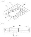
- FIG. 8 illustrates the discharge section shown in FIG. 2 ;
- FIG. 9 illustrates the state where a steel plate introduced into the discharge section shown in FIG. 8 is held by stoppers.
- FIG. 10 illustrates a coupling structure of the stoppers shown in FIG. 8 .
- a hot stamping process comprises heating a steel plate in a heating furnace system, forming and cooling the heated steel plate in a press 600 , and loading the pressed steel plate onto a conveyor 800 .
- Transfer robots 500 and 700 are positioned to transfer the steel plate (or a product) between the heating furnace system and the press 600 , and between the press 600 and the conveyor 800 , respectively.
- the heating furnace system includes a steel plate feed section 100 , heating furnaces 200 and 300 , and a discharge section 400 .
- the heating furnaces 200 and 300 are sorted into a first heating furnace 200 and a second heating furnace 300 .
- the steel plate feed section 100 includes a plurality of feed rolls 110 arranged in a lengthwise direction in order to feed the steel plate to the first heating furnace 200 .
- a length of the steel plate feed section 100 can be adjusted according to a size of the steel plate to be fed, and as needed.
- As the feed rolls 110 stainless rolls are used.
- the first heating furnace 200 is a high-frequency furnace using high-frequency induction heating in order to heat the steel plate, and has two heating zones 200 a and 200 b having different target temperatures.
- Each heating zone is provided with high-frequency coils 220 connected to a separate inverter (not shown).
- the target temperatures are obtained through adjustment of output of the inverter, particularly through frequency modulation.
- the target temperature for heating the steel plate on the first heating zone 200 a has a range between 25° C. and 450° C. (using a relatively low frequency), while the target temperature for heating the steel plate on the second heating zone 200 b has a range between 450° C. and 750° C. (using a relatively high frequency).
- the two heating zones are divided to increase temperature of the steel plate, so that it is possible to prevent deformation or twist of the steel plate caused by a sharp increase in temperature.
- each high-frequency coil 220 is installed in a structure where it sequentially runs between the neighboring upper rolls 210 a , between the pairs of upper and lower rolls 210 , and between the neighboring lower rolls 210 b , i.e. is bent in a quadrilateral shape (see FIG. 5 ).
- the steel plate passing between the upper rolls 210 a and the lower rolls 210 b is almost continuously heated by the high-frequency coils installed in spaces between the rolls.
- the deformation or twist of the steel plate which may occur during heating can be effectively controlled by adjusting an interval between the upper roll 210 a and the lower roll 210 b .
- the high-frequency coils 220 are insulated and coated such that no spark occurs when coming into contact with the steel plate.
- the speed at which the steel plated is transferred at the first heating furnace 200 is adjusted within a range from 70 mm/sec to 90 mm/sec.
- opposite ends of the upper and lower pairs 210 pass through Hemmit panels 230 for thermal insulation, and then are mounted on Bakelite panels 240 defining a case of the first heating furnace 200 .
- the Bakelite panels 240 are used to shield an influence of high frequency as well as maintain an insulating characteristic and strength.
- the opposite ends of the upper and lower pairs 210 passing through these Bakelite panels 240 are connected with drives (not shown), such as sprockets or bearings, for rotating the upper and lower pairs 210 by a typical technique.
- the drive particularly the bearing, to which the upper roll 210 a is connected, may be provided with a damper there outside so as to be able to absorb impact to which the steel plate applies to the upper roll 210 a while passing between the upper roll 210 a and the lower roll 210 b.
- the upper and lower rolls 210 are made of a hollow ceramic material for the insulating characteristic. As illustrated in FIGS. 6 and 7 , extensions 250 are inserted into the opposite ends of the upper and lower rolls 210 in order to lengthen the rolls and to make connection to the drives.
- Yarn 260 is wound on the outer circumference of each roll into which the extension is inserted within a predetermined area. The reason of winding the yarn 260 is to prevent the hollow ceramic rolls vulnerable to impact from being broken by misalignment between central axes of the extensions 250 inserted into the opposite ends of each roll 210 and a central axis of each roll 210 . This wound yarn 260 is impregnated with epoxy resin, thereby increasing strength. As illustrated in FIGS.
- each extension 250 includes an insertion part 215 inserted into the roll 210 , a step 252 fitted to the roll 210 , and an extension part 253 having a smaller diameter than the insertion part 251 .
- the insertion part 251 of the extension 250 is fastened with the roll 210 by bolts 270 .
- the second heating furnace 300 includes an electric furnace or a gas furnace for heating the steel plate transferred from the first heating furnace 200 at temperature of A c3 or more (about 950° C. or more). As illustrated in FIG. 2 , the second heating furnace 300 has five heating zones, and the first heating furnace 200 has two heating zones, so that the inventive heating furnace system has a total of seven heating zones. If the five heating zones of the second heating furnace 300 are called third to seventh heating zones, the third to fifth heating zones are heating sections 300 a for heating the steel plate transferred from the first heating furnace 200 at temperature of A c3 or more, the sixth heating zone is a soaking section 300 b , and the seventh heating zone is a standby section 300 c .
- a reference numeral 320 indicates a heater.
- a plurality of transfer rollers 310 made of heat resisting steel are arranged throughout the entire length of the second heating furnace 300 .
- a steel plate position detection sensor 320 and a temperature detection sensor 330 are installed in the standby section 300 c . These sensors 320 and 330 detect whether or not the steel plate enters the standby section 300 c (i.e. whether or not the steel plate is placed on the transfer rollers of the standby section 300 c throughout the entire length thereof), and whether or not the steel plate is sufficiently soaked at a discharge temperature of A c3 or more. When these conditions are met, the steel plate begins to be discharged from the standby section 300 c to the discharge section 400 .
- the transferring speed of the steel plate in the heating section 300 a is equal to that in the soaking section 300 b .
- the transferring speed of the steel plate in the standby section 300 b is also equal to those in the heating and soaking sections 300 a and 300 b until the steel plate is discharged.
- the transferring speed of the steel plate is set so as to be increased.
- the transferring speed of the steel plate is dependent on the rotating speed of the transfer rollers of the soaking section 300 b , although the rotating speed of the transfer rollers of the standby section 300 c is increased. Further, in the case where the increased rotating speed of the transfer rollers 310 is sharply reduced, the transfer rollers 310 are overloaded to have a possibility of flexure or damage.
- the transferring speed thereof is set in such a manner that it is gradually reduced to be equal to those for the heating and soaking sections 300 a and 300 b .
- the temperature of the steel plate is sharply lowered for several seconds until the steel plate comes out of the standby section 300 c and then is formed by the press 600 .
- the second heating furnace 300 may be supplied with an atmosphere gas in order to prevent oxidation of the steel plate.
- the standby section 300 c of the second heating furnace 300 is followed by the discharge section 400 having rotation rolls 410 for introduction of the steel plate.
- Stoppers 432 are installed upwards between the neighboring rotation rolls 410 in order to fix a position of the introduced steel plate.
- a support plate 430 is installed below the rotation rolls 410 .
- the support plate 430 is formed with a plurality of mounting holes 431 in the axial direction of the rotation rolls 410 . These mounting holes 431 are densely formed so as to be able to install the stoppers 432 at interference positions with the steel plate according to the shape of the heated steel plate.
- the support plate 430 is connected to a frame 420 of the discharge section.
- the rotation rolls 410 of the discharge section 400 continue to be rotated as long as the steel plate is placed thereon. This continuous rotation is for preventing local temperature reduction, deformation, etc. of the steel plate at the places where the steel plate is in contact with the rotation rolls 410 .
- the steel plate which is transferred to the discharge section 400 , is placed between upper and lower dies 610 and 620 of the press by the first transfer robot 500 , and then is formed and heat-treated.
- the upper and lower dies 610 and 620 are each provided with a cooling channel for radiating heat.
- the pressed and heat-treated product is discharged and loaded on the conveyor 800 by the second transfer robot 600 , and then is transferred.
Priority Applications (1)
| Application Number | Priority Date | Filing Date | Title |
|---|---|---|---|
| US15/460,889 US20170183757A1 (en) | 2008-10-02 | 2017-03-16 | Hot stamping method for manufacturing vehicle body parts |
Applications Claiming Priority (2)
| Application Number | Priority Date | Filing Date | Title |
|---|---|---|---|
| KR10-2008-0096912 | 2008-10-02 | ||
| KR1020080096912A KR101045839B1 (ko) | 2008-10-02 | 2008-10-02 | 핫스탬핑용 가열로 장치 |
Related Child Applications (1)
| Application Number | Title | Priority Date | Filing Date |
|---|---|---|---|
| US15/460,889 Continuation-In-Part US20170183757A1 (en) | 2008-10-02 | 2017-03-16 | Hot stamping method for manufacturing vehicle body parts |
Publications (2)
| Publication Number | Publication Date |
|---|---|
| US20100086002A1 US20100086002A1 (en) | 2010-04-08 |
| US9631248B2 true US9631248B2 (en) | 2017-04-25 |
Family
ID=42075780
Family Applications (1)
| Application Number | Title | Priority Date | Filing Date |
|---|---|---|---|
| US12/496,254 Active 2033-02-27 US9631248B2 (en) | 2008-10-02 | 2009-07-01 | Heating furnace system for hot stamping |
Country Status (2)
| Country | Link |
|---|---|
| US (1) | US9631248B2 (ko) |
| KR (1) | KR101045839B1 (ko) |
Cited By (5)
| Publication number | Priority date | Publication date | Assignee | Title |
|---|---|---|---|---|
| WO2019043161A1 (de) * | 2017-09-01 | 2019-03-07 | Schwartz Gmbh | Verfahren zum erwärmen eines metallischen bauteils auf eine zieltemperatur und entsprechender rollenherdofen |
| EP3505266A1 (en) | 2017-12-29 | 2019-07-03 | MS Autotech Co., Ltd. | Hot stamping die apparatus |
| US11219937B2 (en) * | 2016-08-09 | 2022-01-11 | Autotech Engineering S.L. | Centering and selective heating |
| US11583909B2 (en) * | 2019-12-20 | 2023-02-21 | Hyundai Steel Company | Hot-stamped part and method of manufacturing the same |
| US11740023B2 (en) * | 2016-12-22 | 2023-08-29 | Autotech Engineering, S.L. | Method for heating a blank and heating system |
Families Citing this family (19)
| Publication number | Priority date | Publication date | Assignee | Title |
|---|---|---|---|---|
| KR101130861B1 (ko) * | 2011-08-10 | 2012-03-28 | 에스아이에스 주식회사 | 핫 스탬핑 성형장치 및 그 방법 |
| NL2007658C2 (nl) * | 2011-10-26 | 2013-05-01 | Smit Ovens Bv | Inrichting voor het verhitten van een substraat. |
| KR101278967B1 (ko) * | 2011-11-21 | 2013-07-02 | 주식회사 엠에스 오토텍 | 핫스탬핑용 가열장치, 고주파가열로 및 롤러기구 |
| EP2615396A1 (en) * | 2011-12-08 | 2013-07-17 | Linde Aktiengesellschaft | Assembly and method for pre-heating circuit boards for thermoforming |
| DE102011120681A1 (de) * | 2011-12-08 | 2013-06-13 | Linde Aktiengesellschaft | Anlage und Verfahren zum Vorwärmen von Platinen beim Warmumformen |
| KR101153951B1 (ko) * | 2011-12-15 | 2012-06-08 | (주)로파 | 멀티 행거 거치대를 갖는 핫스탬핑 시스템 |
| CN103836942B (zh) * | 2012-11-27 | 2015-11-25 | 宝钢特钢有限公司 | 一种生产钛及钛合金的辊底式电加热炉出钢炉辊控制方法 |
| US9181123B2 (en) | 2012-12-07 | 2015-11-10 | Linde Aktiengesellschaft | Thermal imaging to optimize flame polishing |
| US10321524B2 (en) * | 2014-01-17 | 2019-06-11 | Nike, Inc. | Conveyance curing system |
| US20150202830A1 (en) * | 2014-01-17 | 2015-07-23 | Nike, Inc. | Adjustable Conveyance Curing Method |
| CN104388641A (zh) * | 2014-12-12 | 2015-03-04 | 东莞市豪斯特热冲压技术有限公司 | 一种基于坯料形状特征的柔性化快速加热方法 |
| JP6718710B2 (ja) * | 2016-03-18 | 2020-07-08 | 光洋サーモシステム株式会社 | 熱処理装置 |
| KR102017103B1 (ko) | 2017-02-17 | 2019-09-03 | 주식회사 엠에스 오토텍 | 핫스탬핑 부품의 제조방법 |
| DE102017211076B4 (de) | 2017-06-29 | 2019-03-14 | Thyssenkrupp Ag | Verfahren zum Herstellen eines mit einem Überzug versehenen Stahlbauteils und Stahlbauteil |
| CN209792358U (zh) * | 2019-01-29 | 2019-12-17 | 苏州普热斯勒先进成型技术有限公司 | 一种无氧化加热的热冲压生产线 |
| KR102399887B1 (ko) * | 2020-12-09 | 2022-05-20 | 현대제철 주식회사 | 핫 스탬핑 부품 및 이의 제조 방법 |
| CN113294996A (zh) * | 2021-07-28 | 2021-08-24 | 广东意利克节能科技有限公司 | 一种具有节能储热功能的加热炉及其使用方法 |
| KR102584563B1 (ko) * | 2021-10-29 | 2023-10-04 | 현대제철 주식회사 | 핫 스탬핑 부품 및 이의 제조 방법 |
| KR102551329B1 (ko) * | 2021-10-29 | 2023-07-04 | 현대제철 주식회사 | 핫 스탬핑 부품 및 이의 제조 방법 |
Citations (11)
| Publication number | Priority date | Publication date | Assignee | Title |
|---|---|---|---|---|
| GB1490535A (en) | 1973-11-06 | 1977-11-02 | Norrbottens Jaernverk Ab | Manufacturing a hardened steel article |
| US4117293A (en) * | 1974-11-14 | 1978-09-26 | Bbc Brown, Boveri & Company Limited | Method for conveying a row of forging ingots through an inductive heating apparatus |
| US4315124A (en) * | 1977-11-16 | 1982-02-09 | Asea Aktiebolag | Heating modules for billets in inductive heating furnaces |
| US4373364A (en) * | 1979-11-26 | 1983-02-15 | Hitachi, Ltd. | Method of controlling the temperature of a heating furnace |
| US4500287A (en) * | 1982-11-15 | 1985-02-19 | Carfer S.R.L. | Roller table for single-layer ceramic kilns in general |
| US5487795A (en) * | 1993-07-02 | 1996-01-30 | Dong Won Metal Ind. Co., Ltd. | Method for heat treating an impact beam of automotive vehicle door and a system of the same |
| US5922234A (en) * | 1996-07-19 | 1999-07-13 | Geneva Steel | System apparatus and method for heating metal products in an oscillating induction furnace |
| US5923699A (en) * | 1996-10-15 | 1999-07-13 | Geneva Steel | Induction furnance heating module and gas zone |
| US6259071B1 (en) * | 1999-10-01 | 2001-07-10 | Bricmont, Inc. | Single-point temperature control system for a multi-section line furnace |
| US6460690B1 (en) * | 1999-12-17 | 2002-10-08 | Hirata Corporation | Roller conveyer |
| US20070116591A1 (en) * | 2002-07-25 | 2007-05-24 | Philip Morris Usa Inc. | Inductive heating process control of continuous cast metallic sheets |
Family Cites Families (4)
| Publication number | Priority date | Publication date | Assignee | Title |
|---|---|---|---|---|
| JPS63293123A (ja) * | 1987-05-27 | 1988-11-30 | Kawasaki Steel Corp | 被加熱材の連続加熱制御方法およびその装置 |
| JPH03294455A (ja) * | 1990-04-12 | 1991-12-25 | Daido Steel Co Ltd | アルミスラブ用加熱炉 |
| JP2735402B2 (ja) * | 1991-05-15 | 1998-04-02 | ナカジマ鋼管株式会社 | 大径角形鋼管の熱間成形工法 |
| KR100765723B1 (ko) * | 2006-06-07 | 2007-10-11 | 현대하이스코 주식회사 | 핫스탬핑을 이용한 자동차용 고강도 보강대의 제조방법 |
-
2008
- 2008-10-02 KR KR1020080096912A patent/KR101045839B1/ko active IP Right Grant
-
2009
- 2009-07-01 US US12/496,254 patent/US9631248B2/en active Active
Patent Citations (11)
| Publication number | Priority date | Publication date | Assignee | Title |
|---|---|---|---|---|
| GB1490535A (en) | 1973-11-06 | 1977-11-02 | Norrbottens Jaernverk Ab | Manufacturing a hardened steel article |
| US4117293A (en) * | 1974-11-14 | 1978-09-26 | Bbc Brown, Boveri & Company Limited | Method for conveying a row of forging ingots through an inductive heating apparatus |
| US4315124A (en) * | 1977-11-16 | 1982-02-09 | Asea Aktiebolag | Heating modules for billets in inductive heating furnaces |
| US4373364A (en) * | 1979-11-26 | 1983-02-15 | Hitachi, Ltd. | Method of controlling the temperature of a heating furnace |
| US4500287A (en) * | 1982-11-15 | 1985-02-19 | Carfer S.R.L. | Roller table for single-layer ceramic kilns in general |
| US5487795A (en) * | 1993-07-02 | 1996-01-30 | Dong Won Metal Ind. Co., Ltd. | Method for heat treating an impact beam of automotive vehicle door and a system of the same |
| US5922234A (en) * | 1996-07-19 | 1999-07-13 | Geneva Steel | System apparatus and method for heating metal products in an oscillating induction furnace |
| US5923699A (en) * | 1996-10-15 | 1999-07-13 | Geneva Steel | Induction furnance heating module and gas zone |
| US6259071B1 (en) * | 1999-10-01 | 2001-07-10 | Bricmont, Inc. | Single-point temperature control system for a multi-section line furnace |
| US6460690B1 (en) * | 1999-12-17 | 2002-10-08 | Hirata Corporation | Roller conveyer |
| US20070116591A1 (en) * | 2002-07-25 | 2007-05-24 | Philip Morris Usa Inc. | Inductive heating process control of continuous cast metallic sheets |
Cited By (9)
| Publication number | Priority date | Publication date | Assignee | Title |
|---|---|---|---|---|
| US11219937B2 (en) * | 2016-08-09 | 2022-01-11 | Autotech Engineering S.L. | Centering and selective heating |
| US11740023B2 (en) * | 2016-12-22 | 2023-08-29 | Autotech Engineering, S.L. | Method for heating a blank and heating system |
| WO2019043161A1 (de) * | 2017-09-01 | 2019-03-07 | Schwartz Gmbh | Verfahren zum erwärmen eines metallischen bauteils auf eine zieltemperatur und entsprechender rollenherdofen |
| US11584972B2 (en) | 2017-09-01 | 2023-02-21 | Schwartz Gmbh | Method for heating a metal component to a target temperature and corresponding roller hearth furnace |
| EP3505266A1 (en) | 2017-12-29 | 2019-07-03 | MS Autotech Co., Ltd. | Hot stamping die apparatus |
| US11583909B2 (en) * | 2019-12-20 | 2023-02-21 | Hyundai Steel Company | Hot-stamped part and method of manufacturing the same |
| US11931785B2 (en) | 2019-12-20 | 2024-03-19 | Hyundai Steel Company | Method of manufacturing a hot-stamped part |
| US11931786B2 (en) | 2019-12-20 | 2024-03-19 | Hyundai Steel Company | Method of manufacturing a hot-stamped part |
| US11938530B2 (en) | 2019-12-20 | 2024-03-26 | Hyundai Steel Company | Method of manufacturing a hot-stamped part |
Also Published As
| Publication number | Publication date |
|---|---|
| US20100086002A1 (en) | 2010-04-08 |
| KR20100037692A (ko) | 2010-04-12 |
| KR101045839B1 (ko) | 2011-07-01 |
Similar Documents
| Publication | Publication Date | Title |
|---|---|---|
| US9631248B2 (en) | Heating furnace system for hot stamping | |
| US8075836B2 (en) | Steel-sheet continuous annealing equipment and method for operating steel-sheet continuous annealing equipment | |
| KR101125069B1 (ko) | 핫 스탬핑용 가열로 장치 및 블랭크 가열방법 | |
| US10526677B2 (en) | Heat treatment furnace and method for heat treatment of a pre-coated steel sheet blank and method for production of a motor vehicle part | |
| KR101278967B1 (ko) | 핫스탬핑용 가열장치, 고주파가열로 및 롤러기구 | |
| US20170183757A1 (en) | Hot stamping method for manufacturing vehicle body parts | |
| JP2006257486A (ja) | 方向性電磁鋼板の焼鈍方法及び方向性電磁鋼板のバッチ焼鈍用インナーカバー | |
| JP6083156B2 (ja) | 連続焼鈍設備の急速加熱装置および急速加熱方法 | |
| JP2013216959A (ja) | リング状部材の熱処理設備 | |
| JP5421399B2 (ja) | 高周波誘導連続加熱方法及び高周波誘導連続加熱装置 | |
| KR20080112487A (ko) | 핫스탬핑용 블랭크의 가열방법 | |
| JP7253558B2 (ja) | 熱間圧延インライン移動保温熱処理プロセス及び熱処理ライン | |
| JP2007301574A (ja) | 鋼管の製造方法および鋼管の製造設備 | |
| JPH07173545A (ja) | 金属帯の連続熱処理装置および連続熱処理方法 | |
| CN107475504A (zh) | 一种用于取向硅钢卷高温退火的装置及方法 | |
| JP5906815B2 (ja) | 鋼板のバッチ式焼鈍方法およびバッチ式焼鈍炉 | |
| KR101049843B1 (ko) | 허스롤 장치 | |
| CN107326168A (zh) | 一种铜‑钢‑铜复合材料的热处理系统和方法 | |
| KR101091757B1 (ko) | 핫 스탬핑용 가열로 장치 | |
| KR101858611B1 (ko) | 자동차용 도어 임팩트 빔 제조장치 | |
| CN117344123A (zh) | 一种钢板热处理淬火系统 | |
| CN117344103A (zh) | 一种钢板热处理回火系统 | |
| JPH0437883Y2 (ko) | ||
| CN101602098A (zh) | 大口径炉辊梯度离心铸造工艺 | |
| JPS5818404B2 (ja) | ダイケイウスニクコウカンノヤキイレ ヤキモドシホウホウ |
Legal Events
| Date | Code | Title | Description |
|---|---|---|---|
| AS | Assignment |
Owner name: MS AUTOTECH CO., LTD., KOREA, REPUBLIC OF Free format text: ASSIGNMENT OF ASSIGNORS INTEREST;ASSIGNORS:HWANG, JUNG BOK;KIM, SUN UNG;KIM, WON HYUCK;AND OTHERS;REEL/FRAME:022904/0159 Effective date: 20090622 Owner name: MS AUTOTECH CO., LTD.,KOREA, REPUBLIC OF Free format text: ASSIGNMENT OF ASSIGNORS INTEREST;ASSIGNORS:HWANG, JUNG BOK;KIM, SUN UNG;KIM, WON HYUCK;AND OTHERS;REEL/FRAME:022904/0159 Effective date: 20090622 |
|
| STCF | Information on status: patent grant |
Free format text: PATENTED CASE |
|
| AS | Assignment |
Owner name: MS AUTOTECH CO., LTD., KOREA, REPUBLIC OF Free format text: ASSIGNMENT OF ASSIGNORS INTEREST;ASSIGNOR:MS AUTOTECH CO., LTD.;REEL/FRAME:050286/0541 Effective date: 20190820 Owner name: MYUNGSHIN INDUSTRY CO., LTD., KOREA, REPUBLIC OF Free format text: ASSIGNMENT OF ASSIGNORS INTEREST;ASSIGNOR:MS AUTOTECH CO., LTD.;REEL/FRAME:050286/0541 Effective date: 20190820 |
|
| MAFP | Maintenance fee payment |
Free format text: PAYMENT OF MAINTENANCE FEE, 4TH YR, SMALL ENTITY (ORIGINAL EVENT CODE: M2551); ENTITY STATUS OF PATENT OWNER: SMALL ENTITY Year of fee payment: 4 |