US9585527B2 - Foamer dispenser - Google Patents
Foamer dispenser Download PDFInfo
- Publication number
- US9585527B2 US9585527B2 US14/901,798 US201414901798A US9585527B2 US 9585527 B2 US9585527 B2 US 9585527B2 US 201414901798 A US201414901798 A US 201414901798A US 9585527 B2 US9585527 B2 US 9585527B2
- Authority
- US
- United States
- Prior art keywords
- hollow stem
- air
- airway
- pump
- tubular body
- Prior art date
- Legal status (The legal status is an assumption and is not a legal conclusion. Google has not performed a legal analysis and makes no representation as to the accuracy of the status listed.)
- Active
Links
- 244000273618 Sphenoclea zeylanica Species 0.000 claims abstract description 52
- 238000005187 foaming Methods 0.000 claims description 24
- 239000006260 foam Substances 0.000 claims description 14
- 239000000203 mixture Substances 0.000 claims description 6
- 230000000994 depressogenic effect Effects 0.000 description 11
- 239000011347 resin Substances 0.000 description 6
- 229920005989 resin Polymers 0.000 description 6
- 238000005192 partition Methods 0.000 description 4
- 230000000881 depressing effect Effects 0.000 description 3
- XLYOFNOQVPJJNP-UHFFFAOYSA-N water Substances O XLYOFNOQVPJJNP-UHFFFAOYSA-N 0.000 description 3
- LYCAIKOWRPUZTN-UHFFFAOYSA-N Ethylene glycol Chemical compound OCCO LYCAIKOWRPUZTN-UHFFFAOYSA-N 0.000 description 2
- PEDCQBHIVMGVHV-UHFFFAOYSA-N Glycerine Chemical compound OCC(O)CO PEDCQBHIVMGVHV-UHFFFAOYSA-N 0.000 description 2
- -1 methyl taurate Chemical compound 0.000 description 2
- 239000000344 soap Substances 0.000 description 2
- KRKNYBCHXYNGOX-UHFFFAOYSA-K Citrate Chemical compound [O-]C(=O)CC(O)(CC([O-])=O)C([O-])=O KRKNYBCHXYNGOX-UHFFFAOYSA-K 0.000 description 1
- FBPFZTCFMRRESA-FSIIMWSLSA-N D-Glucitol Natural products OC[C@H](O)[C@H](O)[C@@H](O)[C@H](O)CO FBPFZTCFMRRESA-FSIIMWSLSA-N 0.000 description 1
- DGAQECJNVWCQMB-PUAWFVPOSA-M Ilexoside XXIX Chemical compound C[C@@H]1CC[C@@]2(CC[C@@]3(C(=CC[C@H]4[C@]3(CC[C@@H]5[C@@]4(CC[C@@H](C5(C)C)OS(=O)(=O)[O-])C)C)[C@@H]2[C@]1(C)O)C)C(=O)O[C@H]6[C@@H]([C@H]([C@@H]([C@H](O6)CO)O)O)O.[Na+] DGAQECJNVWCQMB-PUAWFVPOSA-M 0.000 description 1
- 229920003171 Poly (ethylene oxide) Polymers 0.000 description 1
- 206010044565 Tremor Diseases 0.000 description 1
- 230000002411 adverse Effects 0.000 description 1
- 125000000217 alkyl group Chemical group 0.000 description 1
- MRUAUOIMASANKQ-UHFFFAOYSA-O carboxymethyl-[3-(dodecanoylamino)propyl]-dimethylazanium Chemical compound CCCCCCCCCCCC(=O)NCCC[N+](C)(C)CC(O)=O MRUAUOIMASANKQ-UHFFFAOYSA-O 0.000 description 1
- 230000003247 decreasing effect Effects 0.000 description 1
- 230000006866 deterioration Effects 0.000 description 1
- JMGZBMRVDHKMKB-UHFFFAOYSA-L disodium;2-sulfobutanedioate Chemical compound [Na+].[Na+].OS(=O)(=O)C(C([O-])=O)CC([O-])=O JMGZBMRVDHKMKB-UHFFFAOYSA-L 0.000 description 1
- 230000000694 effects Effects 0.000 description 1
- 235000011187 glycerol Nutrition 0.000 description 1
- 235000012907 honey Nutrition 0.000 description 1
- WGCNASOHLSPBMP-UHFFFAOYSA-N hydroxyacetaldehyde Natural products OCC=O WGCNASOHLSPBMP-UHFFFAOYSA-N 0.000 description 1
- 239000004615 ingredient Substances 0.000 description 1
- 229940075468 lauramidopropyl betaine Drugs 0.000 description 1
- 238000000465 moulding Methods 0.000 description 1
- 239000008213 purified water Substances 0.000 description 1
- 239000002453 shampoo Substances 0.000 description 1
- 229910052708 sodium Inorganic materials 0.000 description 1
- 239000011734 sodium Substances 0.000 description 1
- WXMKPNITSTVMEF-UHFFFAOYSA-M sodium benzoate Chemical compound [Na+].[O-]C(=O)C1=CC=CC=C1 WXMKPNITSTVMEF-UHFFFAOYSA-M 0.000 description 1
- 235000010234 sodium benzoate Nutrition 0.000 description 1
- 239000004299 sodium benzoate Substances 0.000 description 1
- HWCHICTXVOMIIF-UHFFFAOYSA-M sodium;3-(dodecylamino)propanoate Chemical compound [Na+].CCCCCCCCCCCCNCCC([O-])=O HWCHICTXVOMIIF-UHFFFAOYSA-M 0.000 description 1
- CRPCXAMJWCDHFM-UHFFFAOYSA-M sodium;5-oxopyrrolidine-2-carboxylate Chemical compound [Na+].[O-]C(=O)C1CCC(=O)N1 CRPCXAMJWCDHFM-UHFFFAOYSA-M 0.000 description 1
- 239000000600 sorbitol Substances 0.000 description 1
- 229940104261 taurate Drugs 0.000 description 1
Images


Classifications
-
- A—HUMAN NECESSITIES
- A47—FURNITURE; DOMESTIC ARTICLES OR APPLIANCES; COFFEE MILLS; SPICE MILLS; SUCTION CLEANERS IN GENERAL
- A47K—SANITARY EQUIPMENT NOT OTHERWISE PROVIDED FOR; TOILET ACCESSORIES
- A47K5/00—Holders or dispensers for soap, toothpaste, or the like
- A47K5/14—Foam or lather making devices
-
- A—HUMAN NECESSITIES
- A47—FURNITURE; DOMESTIC ARTICLES OR APPLIANCES; COFFEE MILLS; SPICE MILLS; SUCTION CLEANERS IN GENERAL
- A47K—SANITARY EQUIPMENT NOT OTHERWISE PROVIDED FOR; TOILET ACCESSORIES
- A47K5/00—Holders or dispensers for soap, toothpaste, or the like
- A47K5/06—Dispensers for soap
- A47K5/12—Dispensers for soap for liquid or pasty soap
- A47K5/1211—Dispensers for soap for liquid or pasty soap using pressure on soap, e.g. with piston
-
- B—PERFORMING OPERATIONS; TRANSPORTING
- B05—SPRAYING OR ATOMISING IN GENERAL; APPLYING FLUENT MATERIALS TO SURFACES, IN GENERAL
- B05B—SPRAYING APPARATUS; ATOMISING APPARATUS; NOZZLES
- B05B11/00—Single-unit hand-held apparatus in which flow of contents is produced by the muscular force of the operator at the moment of use
- B05B11/0005—Components or details
- B05B11/0062—Outlet valves actuated by the pressure of the fluid to be sprayed
- B05B11/0064—Lift valves
-
- B—PERFORMING OPERATIONS; TRANSPORTING
- B05—SPRAYING OR ATOMISING IN GENERAL; APPLYING FLUENT MATERIALS TO SURFACES, IN GENERAL
- B05B—SPRAYING APPARATUS; ATOMISING APPARATUS; NOZZLES
- B05B11/00—Single-unit hand-held apparatus in which flow of contents is produced by the muscular force of the operator at the moment of use
- B05B11/0005—Components or details
- B05B11/0062—Outlet valves actuated by the pressure of the fluid to be sprayed
- B05B11/0075—Two outlet valves being placed in a delivery conduit, one downstream the other
-
- B—PERFORMING OPERATIONS; TRANSPORTING
- B05—SPRAYING OR ATOMISING IN GENERAL; APPLYING FLUENT MATERIALS TO SURFACES, IN GENERAL
- B05B—SPRAYING APPARATUS; ATOMISING APPARATUS; NOZZLES
- B05B11/00—Single-unit hand-held apparatus in which flow of contents is produced by the muscular force of the operator at the moment of use
- B05B11/01—Single-unit hand-held apparatus in which flow of contents is produced by the muscular force of the operator at the moment of use characterised by the means producing the flow
- B05B11/10—Pump arrangements for transferring the contents from the container to a pump chamber by a sucking effect and forcing the contents out through the dispensing nozzle
- B05B11/1001—Piston pumps
-
- B—PERFORMING OPERATIONS; TRANSPORTING
- B05—SPRAYING OR ATOMISING IN GENERAL; APPLYING FLUENT MATERIALS TO SURFACES, IN GENERAL
- B05B—SPRAYING APPARATUS; ATOMISING APPARATUS; NOZZLES
- B05B11/00—Single-unit hand-held apparatus in which flow of contents is produced by the muscular force of the operator at the moment of use
- B05B11/01—Single-unit hand-held apparatus in which flow of contents is produced by the muscular force of the operator at the moment of use characterised by the means producing the flow
- B05B11/10—Pump arrangements for transferring the contents from the container to a pump chamber by a sucking effect and forcing the contents out through the dispensing nozzle
- B05B11/1087—Combination of liquid and air pumps
-
- B—PERFORMING OPERATIONS; TRANSPORTING
- B05—SPRAYING OR ATOMISING IN GENERAL; APPLYING FLUENT MATERIALS TO SURFACES, IN GENERAL
- B05B—SPRAYING APPARATUS; ATOMISING APPARATUS; NOZZLES
- B05B11/00—Single-unit hand-held apparatus in which flow of contents is produced by the muscular force of the operator at the moment of use
- B05B11/01—Single-unit hand-held apparatus in which flow of contents is produced by the muscular force of the operator at the moment of use characterised by the means producing the flow
- B05B11/10—Pump arrangements for transferring the contents from the container to a pump chamber by a sucking effect and forcing the contents out through the dispensing nozzle
- B05B11/1097—Pump arrangements for transferring the contents from the container to a pump chamber by a sucking effect and forcing the contents out through the dispensing nozzle with means for sucking back the liquid or other fluent material in the nozzle after a dispensing stroke
-
- B05B11/3001—
-
- B05B11/3087—
-
- B—PERFORMING OPERATIONS; TRANSPORTING
- B05—SPRAYING OR ATOMISING IN GENERAL; APPLYING FLUENT MATERIALS TO SURFACES, IN GENERAL
- B05B—SPRAYING APPARATUS; ATOMISING APPARATUS; NOZZLES
- B05B7/00—Spraying apparatus for discharge of liquids or other fluent materials from two or more sources, e.g. of liquid and air, of powder and gas
- B05B7/0018—Spraying apparatus for discharge of liquids or other fluent materials from two or more sources, e.g. of liquid and air, of powder and gas with devices for making foam
- B05B7/0025—Spraying apparatus for discharge of liquids or other fluent materials from two or more sources, e.g. of liquid and air, of powder and gas with devices for making foam with a compressed gas supply
- B05B7/0031—Spraying apparatus for discharge of liquids or other fluent materials from two or more sources, e.g. of liquid and air, of powder and gas with devices for making foam with a compressed gas supply with disturbing means promoting mixing, e.g. balls, crowns
- B05B7/0037—Spraying apparatus for discharge of liquids or other fluent materials from two or more sources, e.g. of liquid and air, of powder and gas with devices for making foam with a compressed gas supply with disturbing means promoting mixing, e.g. balls, crowns including sieves, porous members or the like
-
- B—PERFORMING OPERATIONS; TRANSPORTING
- B05—SPRAYING OR ATOMISING IN GENERAL; APPLYING FLUENT MATERIALS TO SURFACES, IN GENERAL
- B05B—SPRAYING APPARATUS; ATOMISING APPARATUS; NOZZLES
- B05B7/00—Spraying apparatus for discharge of liquids or other fluent materials from two or more sources, e.g. of liquid and air, of powder and gas
- B05B7/0018—Spraying apparatus for discharge of liquids or other fluent materials from two or more sources, e.g. of liquid and air, of powder and gas with devices for making foam
- B05B7/005—Spraying apparatus for discharge of liquids or other fluent materials from two or more sources, e.g. of liquid and air, of powder and gas with devices for making foam wherein ambient air is aspirated by a liquid flow
Definitions
- the present disclosure relates to a foamer dispenser that dispenses a mixture of a content medium and air in the form of foam.
- containers filled with shampoo, body soap, hand soap, face cleanser, and so forth are often used with a dispenser that allows the content medium contained in the container to be directly dispensed in the form of foam.
- Such a dispenser includes a base cap, which is held by a mouth of the container, and a single cylinder fitted to the base cap.
- the single cylinder includes coaxially and serially arranged two pistons, i.e., one piston that sucks, pressurizes, and pumps the content medium, and the other piston that sucks, pressurizes, and pumps air.
- the content medium and air are sucked, pressurized, and pumped into the corresponding cylinder portions.
- the content medium and air are mixed together in confluence space located on outlet sides of the pumps and passed through a foaming member such as a mesh.
- a foaming member such as a mesh
- the foaming member is generally assembled to a jet ring (which is called “the foaming member fitting tube” in Patent Literature 1) in advance to facilitate assembly to, for example, a dispenser.
- the jet ring includes, in a lower part thereof, a small-diameter tubular portion that is suited for being inserted into an upper end portion of a stem.
- a foamer dispenser structured as above may face the problem, upon repeated dispensing of the content medium, that the content medium in the confluence space possibly flows backward to an airway communicating with the cylinder.
- the backflow of the content medium accumulates in the air cylinder portion, a supply of air is decreased, resulting in a change in mixture ratio of the content medium and air which may cause deterioration in quality of the foam (e.g., coarsening of foam texture).
- the present disclosure is to solve the above problem, and the present disclosure is to provide a novel foamer dispenser that is capable of preventing backflow of the content medium into the air cylinder to maintain a satisfactory quality of the foam.
- a foamer dispenser including: a base cap held by a mouth of a container; two pumps suspended from and held to the mouth of the container by the base cap, the two pumps being one pump configured to suck, pressurize, and pump a content medium and the other pump configured to suck, pressurize, and pump air; and a nozzle head configured to mix the content medium and the air pumped from the corresponding pumps and to foam the mixture of the content medium and the air by a foaming member disposed inside the nozzle head to be dispensed to outside through an internal passage.
- the pump configured to suck, pressurize, and pump the content medium includes: a small-diameter tubular body provided in a bottom portion thereof with a suction port for inflow of the content medium; a hollow piston disposed in abutment with an inner circumferential surface of the small-diameter tubular body and configured to slide toward the bottom portion of the small-diameter tubular body to pressurize and pump the content medium that is present in the small-diameter tubular body; and a hollow stem including an inner passage through which the content medium pumped from the hollow piston is supplied to the nozzle head and also including a flange protruding from an outer circumferential surface of the hollow stem outward in a radial direction.
- the pump configured to suck, pressurize, and pump the air includes: a large-diameter tubular body including a bottom portion coupled integrally to the small-diameter tubular body; an air piston disposed in abutment with an inner circumferential surface of the large-diameter tubular body and configured to slide toward the bottom portion of the large-diameter tubular body to pressurize and pump the air that is present in the large-diameter tubular body; and a tubular guide that is coupled integrally to the air piston, that surrounds the hollow stem to define a first airway between the hollow stem and the tubular guide, that holds the hollow stem in a manner such that the hollow stem is slidable, and that is configured to come out of abutment with the flange in response to downward sliding of the hollow stem, thereby opening the first airway to supply the air pumped by the air piston to the nozzle head through the first airway.
- the flange is provided with: an outer annular wall protruding upward from an outer edge of the flange; and a guide rib located on an outer side of the tubular guide in the radial direction and configured to be guided by the tubular guide during sliding of the hollow stem.
- the outer annular wall and the flange are coupled integrally via the guide rib.
- the nozzle head includes a jet ring that holds the foaming member
- the jet ring includes: an upper tubular portion surrounding and holding the foaming member; a middle tubular portion coupled integrally to the upper tubular portion and having an outer circumferential wall that is dented inward in the radial direction to support the foaming member from below; and a lower tubular portion that is coupled integrally to the middle tubular portion, that has an inner circumferential surface provided with a plurality of vertical ribs abutting against the outer circumferential surface of the hollow stem to be fitted and held to the hollow stem, and that defines a second airway communicating with the first airway between any two adjacent vertical ribs.
- the jet ring further includes at least one rib that is provided on the outer circumferential wall dented inward in the radial direction and that extends vertically.
- the foamer dispenser of the present disclosure includes a tubular guide that defines the first airway between the hollow stem and the tubular guide, that holds the hollow stem in a manner such that the hollow stem is slidable, and that is configured to come out of abutment with the flange of the hollow stem in response to downward sliding of the hollow stem, thereby opening the first airway to supply the air pumped by the air piston to the nozzle head through the first airway.
- the flange is provided in the outer edge thereof with the outer annular wall protruding upward.
- the outer annular wall effectively prevents the problem of the content medium flowing into the large-diameter tubular body, i.e., the air cylinder portion.
- the flange is provided with the guide rib located on the outer side of the tubular guide in the radial direction, and the guide rib serves to guide the hollow stem while the hollow stem slides relative to the tubular guide. Accordingly, smooth sliding of the hollow stem relative to the tubular guide is achieved.
- the jet ring of the present disclosure includes the middle tubular portion having the outer circumferential wall that is dented inward in the radial direction, the amount of resin is reduced by the reduced dimension. Furthermore, the middle tubular portion of the jet ring holds, from below, the foaming member held in the upper tubular portion and thus, the foaming member is held in a predetermined position. Moreover, the jet ring is configured to be fitted and held to the hollow piston by the plurality of vertical ribs provided on inner circumferential surface of the lower tubular portion, and this structure omits the need for the jet ring to have a small-diameter tubular portion in the upper part as is required in a conventional jet ring. Accordingly, the shape of the jet ring is simplified. Moreover, a gap between any two adjacent vertical ribs may serve as the airway for the air pumped by the air piston.
- the jet ring further includes at least one rib that is provided on the outer circumferential wall dented inward in the radial direction of the jet ring and that extends vertically, the jet ring is reinforced without the need for increasing the amount of resin significantly.
- FIG. 1 is a sectional view of a foamer dispenser that is mounted on a mouth of a container, according to one of embodiments of the present disclosure
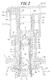
- FIG. 2 is a partially enlarged sectional view of the foamer dispenser of FIG. 1 (in which a stopper is released);
- FIG. 3 is a partially enlarged sectional view of a state where a nozzle head starts to be depressed from the state of FIG. 2 .
- FIG. 1 is a sectional view of a foamer dispenser that is mounted on a mouth of a container, according to one of embodiments of the present disclosure
- FIG. 2 is a partially enlarged sectional view of the foamer dispenser of FIG. 1
- FIG. 3 is a partially enlarged sectional view of a state where a nozzle head starts to be depressed from the state of FIG. 2
- FIG. 2 illustrates a state (hereinafter, called “the initial position”) where a stopper of FIG. 1 is released and where a nozzle head is urged upward by a spring which is later described to be ready to be depressed.
- an “upward” direction and a “downward” direction refer to directions defined when a container mounted with the foamer dispenser is in use.
- Reference numeral 1 in FIG. 1 denotes a base cap that is held to a mouth of a container C.
- the base cap 1 includes a top surface wall 1 a and an outer wall 1 b suspended from an edge portion of the top surface wall 1 a , and the outer wall 1 b is provided on an inner side thereof with a screw portion configured to be screwed with a screw portion provided in the mouth of the container C to be held thereto detachably.
- the base cap 1 may be held to the container C by using any known structure, such as an undercut.
- the base cap 1 further includes a hollow neck portion 1 c extending upward from the middle of the top surface wall 1 a .
- the hollow neck 1 portion 1 c is provided, in an upper part thereof, with an annular convex portion 1 d protruding outward in the radial direction and is also provided, on an inner circumferential surface thereof, with a rib 1 e extending vertically.
- the hollow neck portion 1 c defines, inside thereof, a through hole if extending along the outer wall 1 b to communicate with the inside of the container.
- Reference numerals 2 and 3 denote two pumps suspended from and held to the mouth of the container C and respectively configured to suck, pressurize, and pump a content medium and air.
- the content medium pump 2 and the air pump 3 are formed by a single cylinder 4 including a small-diameter tubular body 4 a and a large-diameter tubular body 4 b arranged coaxially in series. A bottom portion of the large-diameter tubular body 4 b is coupled integrally to an upper portion of the small-diameter tubular body 4 a .
- the cylinder 4 is provided, in an upper portion thereof, with a flange extending outward in the radial direction.
- a gasket is disposed on a lower surface side of the flange to be sandwiched between the flange and the mouth of the container C.
- the content medium pump 2 includes a suction port 4 c provided in a bottom portion of the small-diameter tubular body 4 a for inflow of the content medium contained in the container C.
- the content medium pump 2 further includes a fitting tube 4 d provided in an edge portion of the suction port 4 c .
- a suction pipe p extending toward a bottom portion of the container C is fitted to and held by the fitting tube 4 d .
- a hollow piston 5 is disposed in abutment with an inner circumferential surface of the small-diameter tubular body 4 a in a manner such that the hollow piston 5 is slidable along an axis of the small-diameter tubular body 4 a .
- the hollow piston 5 is provided inside thereof with an internal passage t 1 , in which a poppet 6 is disposed.
- An upper portion of the hollow piston 5 is reduced in diameter to form a stepped portion 5 a .
- the poppet 6 includes, in a lower end thereof, a valve portion 6 a configured to open and close the suction port 4 c , and the poppet 6 also includes, in an upper end thereof, a valve portion 6 b configured to open and close an outlet of the internal passage t 1 .
- a hollow stem 7 is disposed on an outer side of the hollow piston 5 .
- the hollow stem 7 includes a lower tubular wall 7 a surrounding the hollow piston 5 , a flange (a middle flange) 7 b coupled integrally to the lower tubular wall 7 a in an upper portion of the lower tubular wall 7 a , and an upper tubular wall 7 c standing on the middle flange 7 b to extend through the through hole if of the base cap 1 .
- a spring 8 is disposed between the poppet 6 and the hollow piston 5 . Accordingly, the hollow piston 5 and the hollow stem 7 are elastically supported in a slidable manner.
- the aforementioned middle flange 7 b protrudes from an outer circumferential surface of the upper tubular wall 7 c outward in the radial direction, and an edge portion of the middle flange 7 b that is located on an inner circumferential side thereof is configured to abut against the stepped portion 5 a of the hollow piston 5 . Furthermore, the middle flange 7 b is provided with an annular wall (a middle annular wall) 7 d standing on an upper surface of the middle flange 7 b .
- the above structure creates concave space S 1 , which is open upward, to be defined by the outer circumferential surface of the upper tubular wall 7 c , the middle flange 7 b , and the middle annular wall 7 d .
- the middle flange 7 b is also provided with an inclined wall 7 e that is coupled integrally to an upper portion of the middle annular wall 7 d and that is inclined upward toward an outer side in the radial direction.
- the inclined wall 7 e has an outer edge to which an outer annular wall 7 f is coupled integrally.
- the outer annular wall 7 f in the present embodiment has an upper portion protruding upward from an upper surface of the inclined wall 7 e .
- a guide rib r is provided on an upper surface of the inclined wall 7 e .
- the guide rib r is located on an outer side of a tubular guide 10 a at a distance therefrom in the circumferential direction.
- the inclined wall 7 e and the outer annular wall 7 f are connected via the guide rib r.
- the hollow stem 7 further includes, in an upper portion of the upper tubular wall 7 c , an inward flange 7 g extending inward in the radial direction. Above the inward flange 7 g , a ball valve B configured to be held against the inward flange 7 g as a valve seat, and a cover member 9 configured to be fitted to and held by the upper tubular wall 7 c and to prevent the ball valve B from slipping out.
- the cover member 9 herein includes an annular lower wall 9 a configured to be locked against an inner circumferential surface of the upper tubular wall 7 c , a plurality of leg portions 9 b coupled integrally to the lower wall 9 a and disposed at an interval in the circumferential direction, a flat plate wall 9 c which is coupled integrally to upper portions of the leg portions 9 b , and an annular upper wall 9 d standing on the flat plate wall 9 c.
- the air pump 3 includes an air piston 10 configured to abut against an inner circumferential surface of the large-diameter tubular body 4 b and disposed slidably along an axis thereof.
- the air piston 10 includes, on an inner side thereof in the radial direction, a tubular guide 10 a surrounding the hollow stem 7 and protruding thorough the through hole if of the base cap 1 in the initial position.
- a gap between an outer side of the hollow stem 7 and an inner side of the tubular guide 10 a defines an airway (the first airway) A 1 disposed above the concave space S 1 for letting air pass.
- the tubular guide 10 a In the initial position, a lower end of the tubular guide 10 a abuts against at least one of the middle flange 7 b and the middle annular wall 7 d .
- the hollow stem 7 may slightly slide relative to the air piston 10 and serves as a valve that opens and closes the first airway A 1 by the lower end of the tubular guide 10 a coming into and out of abutment with the middle flange 7 b (and/or the middle annular wall 7 d ).
- the tubular guide 10 a is provided, on an outer circumferential surface thereof, with a plurality of ribs 10 b .
- a partition wall 10 c extends outward in the radial direction to define space between the tubular guide 10 a and the large-diameter tubular body 4 b in which air is pressurized, and the partition wall 10 c is provided with an opening 10 d through which air is introduced into the large-diameter tubular body 4 b .
- the partition wall 10 c is also provided, on a lower surface thereof, with an annular rib 10 e suspended from an inner side of the opening 10 d in the radial direction.
- the annular rib 10 e is fitted with and holds a check valve 11 that opens and closes the opening 10 d.
- a nozzle head 14 in which a mixture of the content medium and air is foamed by foaming members (mesh rings) 12 disposed inside the hollow stem 7 and from which the foamed mixture is dispensed to the outside through an internal passage 14 a .
- the nozzle head 14 in the present embodiment includes a jet ring 13 configured to hold the mesh rings 12 , and the mesh rings 12 are held in the nozzle head 14 by way of the jet ring 13 .
- the mesh rings 12 in the present embodiment each include a ring-shaped main body portion having one end to which a mesh is attached.
- the mesh ring used herein has a larger dimension (diameter) than a conventional mesh ring.
- a total of two mesh rings 12 are attached to the jet ring 13 in a manner such that the mesh of each mesh ring faces to an outer side (i.e., that other ends of the mesh rings to which a mesh is not attached are joined to each other).
- the jet ring 13 includes an upper tubular portion 13 a surrounding and holding the mesh ring 12 , an a middle tubular portion 13 c coupled integrally to the upper tubular portion 13 a and having an outer circumferential wall 13 b that is dented inward in the radial direction to support the foaming member from below, and a lower tubular portion 13 d coupled integrally to the middle tubular portion 13 c and having a lower end portion configured to surround an upper end portion of the tubular guide 10 a .
- the above structure reduces a diameter of the middle tubular portion 13 c and allows reduction in amount of resin to be used.
- the outer circumferential wall 13 b which is dented on the inner side in the radial direction, is capable of supporting the mesh ring 12 from below.
- the lower tubular portion 13 d has an inner circumferential surface that is provided with a plurality of vertical ribs 13 e configured to abut against the outer circumferential surface of the upper tubular wall 7 c to fit and hold the jet ring 13 thereto.
- the vertical ribs 13 e each extend vertically along an axis of the lower tubular portion 13 d and have an upper portion extending to the inner side in the radial direction along a lower surface of the middle tubular portion 13 c .
- a gap (the second airway A 2 ), which communicates with the first airway A 1 and which extends vertically along the axis of the lower tubular portion 13 d and extends to the inner side in the radial direction along the lower surface of the middle tubular portion 13 c , is defined between any two adjacent vertical ribs 13 e .
- the outer circumferential wall 13 b of the middle tubular portion 13 c is provided with at least one rib 13 f (several ribs 13 f in the present embodiment) that extends vertically.
- the above structure reinforces the middle tubular portion 13 c having a small-diameter.
- a gap having a length L is defined between a lower end of the lower tubular portion 13 d and each rib 10 b of the air piston 10 .
- the nozzle head 14 further includes a nozzle head main body portion 14 b , in which an internal passage 14 a for inflow of the content medium is defined, and a head ring 14 c configured to be positioned on an outer side of the hollow neck portion 1 c of the base cap 1 in the radial direction when the nozzle head 14 is depressed.
- the nozzle head main body portion 14 b is provided, on a back surface thereof, with an inner tubular wall 14 d to which the upper tubular portion 13 a is fitted and held, a rib 14 e configured to prevent the mesh ring 12 mounted to the jet ring 13 from slipping out upward, and an annular fitting wall 14 f between which and the rib 14 e the head ring 14 c is fitted and held.
- the nozzle head main body portion 14 b also has an outer edge provided with an edge wall 14 g surrounding an upper portion of the head ring 14 c .
- the upper portion of the head ring 14 c may be partially cut out so that air may be introduced between the head ring 14 c and the inner tubular wall 14 d from the outside through the cut-out.
- the head ring 14 c is provided, in a lower end portion thereof, with an annular convex portion 14 h protruding inward in the radial direction and is also provided, on an inner surface thereof, with a rib 14 j extending vertically and protruding to substantially the same extent as the convex portion 14 h.
- a stopper 15 configured to prevent the nozzle head 14 to be depressed unintentionally.
- the stopper 15 in its plan view, has a substantially C shape, and may be mounted detachably from a lateral side of the hollow neck portion 1 c.
- the hollow stem 7 according to the present disclosure, with the guide rib r provided in the middle flange 7 b , is capable of sliding smoothly under the guide of the outer circumferential surface of the tubular guide 10 a , thereby preventing such a problem effectively.
- the displaced air piston 10 pressurizes air that is present inside the air piston 10 , and the pressurized air flows along the first airway A 1 and the second airway A 2 toward space (confluence space G) defined by the cover member 9 and the jet ring 13 .
- the valve portion 6 a of the poppet 6 comes into abutment against an inner surface of the small-diameter tubular body 4 a to close the suction port 4 c , and an inside of the small-diameter tubular body 4 a is pressurized.
- the valve portion 6 b of the poppet 6 comes off the outlet of the internal passage t 1 provided in the hollow piston 5 , and the content medium that is present in the internal passage t 1 flows into an inside of the upper tubular wall 7 c (an inner passage t 2 ) of the hollow stem 7 .
- the flowing content medium is once segmented into several streams between adjacent leg portions 9 b (passages t 3 ) and then, gathers again into a cylindrical single passage (a passage t 4 ) defined between the upper tubular wall 7 c and the upper wall 9 d . Subsequently, the content medium, together with the air that has passed through the second airway A 2 , flows to the confluence space G.
- the content medium which has been mixed with air in the confluence space G, passes through the mesh rings 12 to be foamed and flows along the internal passage 14 a provided in the nozzle head 14 to be dispensed to the outside.
- the check valve 11 which has closed the opening 10 d , comes off the opening 10 d , and air flows to the inside of the air piston 10 from the cut-out (which is not illustrated) formed in the upper portion of the head ring 14 c through space between the head ring 14 c and the inner tubular wall 14 d , an inside of the hollow neck portion 1 c included in the base cap 1 , and the opening 10 d .
- the large-diameter tubular body 4 b is provided, in an upper portion thereof, with a lateral hole 4 e as illustrated in FIG. 1 , and the air flowing through the inside of the hollow neck portion 1 c included in the base cap 1 also flows into the container C through the lateral hole 4 e .
- the outer annular wall 7 f provided in the outer edge of the middle flange 7 b effectively prevents the problem of the content medium dripping to the large-diameter tubular body 4 b . Accordingly, a satisfactory quality of the foam is maintained. Furthermore, since in the present embodiment the concave space S 1 is defined below the first airway A 1 , the backflow of the content medium may be pooled, and moreover, the content medium is likely to return to the concave space S 1 by the inclined wall 7 e . Accordingly, it is further ensured that a satisfactory quality of the foam is maintained.
- a gap between the hollow neck portion 1 c of the base cap 1 and the head ring 14 c of the nozzle head 14 is reduced by the convex portion 1 d of the base cap 1 and the convex portion 14 h of the nozzle head 14 .
- This structure prevents water from entering into the foamer dispenser from the outside.
- the edge wall 14 g of the nozzle head main body portion 14 b covers the cut-out (which is not illustrated) formed in the upper portion of the head ring 14 c to serve as an air inlet into the foamer dispenser. This structure prevents water from entering through the cut-out effectively.
- the ribs 10 b are provided in the tubular guide 10 a of the air piston 10
- the rib 1 e is provided on the inner circumferential surface of the hollow neck portion 1 c of the base cap 1
- the rib 14 j is provided on the inner surface of the head ring 14 c of the nozzle head 14 . Accordingly, although portions of the nozzle head 14 that oppose to the ribs might be pressed against the ribs when the nozzle head 14 is depressed obliquely, the contact area is reduced due to the ribs, and satisfactory operability is maintained without having to apply a very strong depressing force.
- the foamer dispenser of the present embodiment was mounted to a container filled with a content medium (a skin cleanser) indicated in Table 1 , and a dispensing condition of the content medium was studied. It has been confirmed that the content medium may be dispensed in the form of foam of a satisfactory quality from beginning to end of use. Furthermore, operability (in terms of pressing force and depression in various directions) of the nozzle head has been found satisfactory.
- a content medium a skin cleanser
- the foamer dispenser of the present disclosure prevents backflow of the content medium into the air cylinder and accordingly, maintains a satisfactory quality of the foam. Furthermore, even when upsizing of the foaming member is required to increase the dose of the content medium per actuation, the amount of resin to be used in the jet ring is minimized, and the shape of the jet ring is simplified.
Landscapes
- Health & Medical Sciences (AREA)
- Public Health (AREA)
- Closures For Containers (AREA)
- Containers And Packaging Bodies Having A Special Means To Remove Contents (AREA)
- Engineering & Computer Science (AREA)
- Mechanical Engineering (AREA)
Applications Claiming Priority (5)
| Application Number | Priority Date | Filing Date | Title |
|---|---|---|---|
| JP2013148884A JP6058494B2 (ja) | 2013-07-17 | 2013-07-17 | フォーマーディスペンサー |
| JP2013148885A JP6058495B2 (ja) | 2013-07-17 | 2013-07-17 | フォーマーディスペンサー |
| JP2013-148884 | 2013-07-17 | ||
| JP2013-148885 | 2013-07-17 | ||
| PCT/JP2014/002575 WO2015008414A1 (fr) | 2013-07-17 | 2014-05-16 | Distributeur de produit moussant |
Publications (2)
| Publication Number | Publication Date |
|---|---|
| US20160367084A1 US20160367084A1 (en) | 2016-12-22 |
| US9585527B2 true US9585527B2 (en) | 2017-03-07 |
Family
ID=52345900
Family Applications (1)
| Application Number | Title | Priority Date | Filing Date |
|---|---|---|---|
| US14/901,798 Active US9585527B2 (en) | 2013-07-17 | 2014-05-16 | Foamer dispenser |
Country Status (7)
| Country | Link |
|---|---|
| US (1) | US9585527B2 (fr) |
| EP (1) | EP3023359B1 (fr) |
| KR (1) | KR101697040B1 (fr) |
| CN (1) | CN105339280B (fr) |
| AU (1) | AU2014291591B2 (fr) |
| CA (1) | CA2919672C (fr) |
| WO (1) | WO2015008414A1 (fr) |
Cited By (1)
| Publication number | Priority date | Publication date | Assignee | Title |
|---|---|---|---|---|
| US20190060932A1 (en) * | 2013-07-17 | 2019-02-28 | Yoshino Kogyosho Co., Ltd. | Foamer dispenser, and container with foamer dispenser |
Families Citing this family (3)
| Publication number | Priority date | Publication date | Assignee | Title |
|---|---|---|---|---|
| CA2837774A1 (fr) | 2013-12-20 | 2015-06-20 | Heiner Ophardt | Pompe a piston avec casse-vide |
| DE102016108447A1 (de) * | 2016-05-06 | 2017-11-09 | S O L O Kleinmotoren Gesellschaft Mit Beschränkter Haftung | Verschäumungseinheit zum Erzeugen von Schaum aus einem Gemisch aus Gas und Flüssigkeit sowie Sprühgerät zum Erzeugen und Verteilen von Schaum |
| EP3513695A1 (fr) * | 2018-01-22 | 2019-07-24 | Praise Glory Limited | Moussant de lait portable |
Citations (13)
| Publication number | Priority date | Publication date | Assignee | Title |
|---|---|---|---|---|
| JPH08230961A (ja) | 1994-12-12 | 1996-09-10 | Yoshino Kogyosho Co Ltd | 泡放出用ポンプ容器 |
| US6053364A (en) * | 1995-10-06 | 2000-04-25 | Airspray N.V. | Device for dispensing an air-liquid mixture, in particular foam, and operating unit intended therefor |
| US6536629B2 (en) * | 1999-06-23 | 2003-03-25 | Airspray N.V. | Aerosol for dispensing a liquid |
| JP2004121889A (ja) | 2002-09-30 | 2004-04-22 | Yoshino Kogyosho Co Ltd | 泡噴出器 |
| US6840408B1 (en) * | 2003-08-25 | 2005-01-11 | Continental Afa Dispensing Company | Air foam pump with shifting air piston |
| US20060219738A1 (en) * | 2004-02-20 | 2006-10-05 | Shigeo Iizuka | Foamer dispenser |
| JP2009202097A (ja) | 2008-02-27 | 2009-09-10 | Kao Corp | 泡吐出器 |
| US7757899B2 (en) * | 2005-04-29 | 2010-07-20 | Rexam Airspray N.V. | Dispensing device |
| JP2011156445A (ja) | 2010-01-29 | 2011-08-18 | Kao Corp | 泡吐出器 |
| US8079497B2 (en) * | 2005-04-20 | 2011-12-20 | Meadwestvaco Calmar Netherlands B.V. | Dispenser with improved supply-closing means |
| US8496142B2 (en) * | 2011-03-22 | 2013-07-30 | Daiwa Can Company | Foam-dispensing pump container |
| US20130313285A1 (en) * | 2011-01-31 | 2013-11-28 | Yoshino Kogyosho Co., Ltd. | Foam dispenser |
| US20160167075A1 (en) * | 2013-07-17 | 2016-06-16 | Yoshino Kogyosho Co., Ltd. | Foamer dispenser, and container with foamer dispenser |
Family Cites Families (5)
| Publication number | Priority date | Publication date | Assignee | Title |
|---|---|---|---|---|
| US5813576A (en) * | 1994-11-17 | 1998-09-29 | Yoshino Kogyosho Co., Ltd. | Container with a pump that mixes liquid and air to discharge bubbles |
| BR9707228A (pt) * | 1996-01-31 | 1999-12-28 | Airspray Int Bv | Aerosol, recipiente auxiliar, e. conjunto de distribuição. |
| JP2005193972A (ja) * | 2003-12-08 | 2005-07-21 | Lion Corp | 液体洗浄剤入りフォーマーポンプ容器及びフォーマーポンプ容器充填用洗浄剤組成物 |
| EP1911525B1 (fr) * | 2005-07-29 | 2012-04-11 | Yoshino Kogyosho Co., Ltd. | Conteneur d' éjection |
| US20090008412A1 (en) * | 2007-04-10 | 2009-01-08 | Choi Hee Jin | Foam pump dispenser having leakage prevention function against reverse flow |
-
2014
- 2014-05-16 KR KR1020157036935A patent/KR101697040B1/ko active IP Right Grant
- 2014-05-16 EP EP14826859.2A patent/EP3023359B1/fr active Active
- 2014-05-16 WO PCT/JP2014/002575 patent/WO2015008414A1/fr active Application Filing
- 2014-05-16 CA CA2919672A patent/CA2919672C/fr active Active
- 2014-05-16 US US14/901,798 patent/US9585527B2/en active Active
- 2014-05-16 AU AU2014291591A patent/AU2014291591B2/en active Active
- 2014-05-16 CN CN201480037310.9A patent/CN105339280B/zh active Active
Patent Citations (13)
| Publication number | Priority date | Publication date | Assignee | Title |
|---|---|---|---|---|
| JPH08230961A (ja) | 1994-12-12 | 1996-09-10 | Yoshino Kogyosho Co Ltd | 泡放出用ポンプ容器 |
| US6053364A (en) * | 1995-10-06 | 2000-04-25 | Airspray N.V. | Device for dispensing an air-liquid mixture, in particular foam, and operating unit intended therefor |
| US6536629B2 (en) * | 1999-06-23 | 2003-03-25 | Airspray N.V. | Aerosol for dispensing a liquid |
| JP2004121889A (ja) | 2002-09-30 | 2004-04-22 | Yoshino Kogyosho Co Ltd | 泡噴出器 |
| US6840408B1 (en) * | 2003-08-25 | 2005-01-11 | Continental Afa Dispensing Company | Air foam pump with shifting air piston |
| US20060219738A1 (en) * | 2004-02-20 | 2006-10-05 | Shigeo Iizuka | Foamer dispenser |
| US8079497B2 (en) * | 2005-04-20 | 2011-12-20 | Meadwestvaco Calmar Netherlands B.V. | Dispenser with improved supply-closing means |
| US7757899B2 (en) * | 2005-04-29 | 2010-07-20 | Rexam Airspray N.V. | Dispensing device |
| JP2009202097A (ja) | 2008-02-27 | 2009-09-10 | Kao Corp | 泡吐出器 |
| JP2011156445A (ja) | 2010-01-29 | 2011-08-18 | Kao Corp | 泡吐出器 |
| US20130313285A1 (en) * | 2011-01-31 | 2013-11-28 | Yoshino Kogyosho Co., Ltd. | Foam dispenser |
| US8496142B2 (en) * | 2011-03-22 | 2013-07-30 | Daiwa Can Company | Foam-dispensing pump container |
| US20160167075A1 (en) * | 2013-07-17 | 2016-06-16 | Yoshino Kogyosho Co., Ltd. | Foamer dispenser, and container with foamer dispenser |
Non-Patent Citations (1)
| Title |
|---|
| Aug. 12, 2014 International Search Report issued in International Patent Application No. PCT/JP2014/002575. |
Cited By (2)
| Publication number | Priority date | Publication date | Assignee | Title |
|---|---|---|---|---|
| US20190060932A1 (en) * | 2013-07-17 | 2019-02-28 | Yoshino Kogyosho Co., Ltd. | Foamer dispenser, and container with foamer dispenser |
| US10758925B2 (en) * | 2013-07-17 | 2020-09-01 | Yoshino Kogyosho Co., Ltd. | Foamer dispenser, and container with foamer dispenser |
Also Published As
| Publication number | Publication date |
|---|---|
| CN105339280A (zh) | 2016-02-17 |
| KR20160014046A (ko) | 2016-02-05 |
| KR101697040B1 (ko) | 2017-01-16 |
| CA2919672C (fr) | 2017-10-31 |
| EP3023359A1 (fr) | 2016-05-25 |
| CA2919672A1 (fr) | 2015-01-22 |
| EP3023359B1 (fr) | 2018-06-27 |
| AU2014291591A1 (en) | 2016-01-28 |
| EP3023359A4 (fr) | 2017-03-29 |
| WO2015008414A1 (fr) | 2015-01-22 |
| AU2014291591B2 (en) | 2016-07-21 |
| CN105339280B (zh) | 2017-04-26 |
| US20160367084A1 (en) | 2016-12-22 |
Similar Documents
| Publication | Publication Date | Title |
|---|---|---|
| AU2014209540B2 (en) | Pumps with container vents | |
| US8313008B2 (en) | Pull actuated foam pump | |
| US10434532B2 (en) | Three piece pump | |
| US9585527B2 (en) | Foamer dispenser | |
| US8591207B2 (en) | Pump with side inlet valve for improved functioning in an inverted container | |
| US11759804B2 (en) | Two stage foam pump and method of producing foam | |
| US20130094983A1 (en) | Diaphragm foam pump for foam dispensers and refill units | |
| US10150127B2 (en) | Foam dispensing assembly | |
| US20190060932A1 (en) | Foamer dispenser, and container with foamer dispenser | |
| JP2010126235A (ja) | フォーマーディスペンサー | |
| JP5964069B2 (ja) | 泡吐出器 | |
| JP6431337B2 (ja) | 泡吐出器 | |
| JP6431355B2 (ja) | 泡吐出器 | |
| JP6096632B2 (ja) | フォーマーディスペンサー | |
| JP2015098332A (ja) | 泡吐出器 | |
| JP2020104930A (ja) | フォーマーディスペンサー | |
| JP2019119472A (ja) | フォーマーディスペンサー | |
| JP6058494B2 (ja) | フォーマーディスペンサー | |
| JP2016132475A (ja) | 泡吐出器 | |
| JP2013035570A (ja) | 泡吐出器 | |
| JP2015077996A (ja) | 泡吐出器 | |
| JP2015020761A (ja) | フォーマーディスペンサー | |
| JP2013035568A (ja) | 泡吐出器 | |
| JP2013035571A (ja) | 泡吐出器 |
Legal Events
| Date | Code | Title | Description |
|---|---|---|---|
| AS | Assignment |
Owner name: YOSHINO KOGYOSHO CO., LTD., JAPAN Free format text: ASSIGNMENT OF ASSIGNORS INTEREST;ASSIGNORS:MIZUSHIMA, HIROSHI;SASAKI, TSUYOSHI;REEL/FRAME:037374/0894 Effective date: 20151109 |
|
| STCF | Information on status: patent grant |
Free format text: PATENTED CASE |
|
| MAFP | Maintenance fee payment |
Free format text: PAYMENT OF MAINTENANCE FEE, 4TH YEAR, LARGE ENTITY (ORIGINAL EVENT CODE: M1551); ENTITY STATUS OF PATENT OWNER: LARGE ENTITY Year of fee payment: 4 |
|
| MAFP | Maintenance fee payment |
Free format text: PAYMENT OF MAINTENANCE FEE, 8TH YEAR, LARGE ENTITY (ORIGINAL EVENT CODE: M1552); ENTITY STATUS OF PATENT OWNER: LARGE ENTITY Year of fee payment: 8 |