US9525403B2 - Clock frequency modulation method and clock frequency modulation apparatus - Google Patents
Clock frequency modulation method and clock frequency modulation apparatus Download PDFInfo
- Publication number
- US9525403B2 US9525403B2 US14/693,522 US201514693522A US9525403B2 US 9525403 B2 US9525403 B2 US 9525403B2 US 201514693522 A US201514693522 A US 201514693522A US 9525403 B2 US9525403 B2 US 9525403B2
- Authority
- US
- United States
- Prior art keywords
- digital
- clock
- clocks
- sequence
- frequency
- Prior art date
- Legal status (The legal status is an assumption and is not a legal conclusion. Google has not performed a legal analysis and makes no representation as to the accuracy of the status listed.)
- Active, expires
Links
Images


Classifications
-
- H—ELECTRICITY
- H03—ELECTRONIC CIRCUITRY
- H03K—PULSE TECHNIQUE
- H03K5/00—Manipulating of pulses not covered by one of the other main groups of this subclass
- H03K5/00006—Changing the frequency
-
- G—PHYSICS
- G06—COMPUTING OR CALCULATING; COUNTING
- G06F—ELECTRIC DIGITAL DATA PROCESSING
- G06F1/00—Details not covered by groups G06F3/00 - G06F13/00 and G06F21/00
- G06F1/04—Generating or distributing clock signals or signals derived directly therefrom
- G06F1/10—Distribution of clock signals, e.g. skew
-
- G—PHYSICS
- G06—COMPUTING OR CALCULATING; COUNTING
- G06F—ELECTRIC DIGITAL DATA PROCESSING
- G06F1/00—Details not covered by groups G06F3/00 - G06F13/00 and G06F21/00
- G06F1/16—Constructional details or arrangements
- G06F1/18—Packaging or power distribution
- G06F1/189—Power distribution
-
- H—ELECTRICITY
- H03—ELECTRONIC CIRCUITRY
- H03K—PULSE TECHNIQUE
- H03K19/00—Logic circuits, i.e. having at least two inputs acting on one output; Inverting circuits
- H03K19/003—Modifications for increasing the reliability for protection
- H03K19/00346—Modifications for eliminating interference or parasitic voltages or currents
-
- H—ELECTRICITY
- H03—ELECTRONIC CIRCUITRY
- H03K—PULSE TECHNIQUE
- H03K21/00—Details of pulse counters or frequency dividers
Definitions
- the present invention relates to the communications field, and more specifically, to a clock frequency modulation method and a clock frequency modulation apparatus.
- a radio-on-chip (ROC, Radio on Chip) has been developed.
- the ROC integrates a digital circuit and a radio frequency (RF, Radio Frequency) circuit into a single chip, so as to greatly reduce an area of a board and cost of a base station, and further minimize power consumption so as to meet the trend of Power over Ethernet (PoE, Power over Ethernet).
- RF radio frequency
- the ROC introduces a new problem, that is, interference of the digital circuit on the RF circuit.
- a relatively large charge/discharge current exists because the digital circuit in the ROC basically turns over near a rising edge of the clock. Consequently, a high-energy interfering pulse signal is generated near the rising edge.
- an interfering pulse signal or a harmonic derived from the interfering pulse signal may fall within some radio frequency bands, thereby resulting in worsening of receiving sensitivity, saturation of a receiving ADC, or deterioration of an EVM of a signal, so that an indicator requirement in a protocol cannot be met.
- how to avoid interference of the digital circuit on the RF circuit is very important for ensuring performance of the ROC.
- Embodiments of the present invention propose a clock frequency modulation method and a clock frequency modulation apparatus used in digital-analog interference suppression, so as to solve a problem of how to adjust clock frequency to achieve effective digital-analog interference suppression.
- a clock frequency modulation method including: determining N digital clocks according to a first digital clock of a system, where the N digital clocks include a second digital clock and N-1 digital clocks except the second digital clock, and a sum of a frequency ratio of the first digital clock to each of the N-1 digital clocks is equal to N-1 times a frequency ratio of the first digital clock to the second digital clock, where N is an integer greater than 2; and fitting, during a modulation period by using the N digital clocks, the first digital clock into the periodic second digital clock.
- the N digital clocks are separately integer frequency dividing clocks of the first digital clock, and frequency dividing coefficients of the N digital clocks are different from each other.
- the fitting, during a modulation period by using the N digital clocks, the first digital clock into the periodic second digital clock includes: mapping, during the modulation period, the N digital clocks separately to a pseudo-random noise PN sequence with a length of M, so as to randomize frequency jitter of the N digital clocks, where a probability that each of the N digital clocks appears in the modulation period is equal, a cyclic period of the PN sequence is equal to the modulation period, N is less than or equal to 2 M , and M is a positive integer; and fitting, during the modulation period by using the N digital clocks mapped to the PN sequence, the first digital clock into the periodic second digital clock.
- the mapping the N digital clocks separately to a pseudo-random noise PN sequence with a length of M includes: mapping, when N is equal to 2 M , the N-1 digital clocks to 2 M -1 cyclic states of the PN sequence in a one-to-one manner; and mapping the second digital clock to a dead state of the PN sequence, where the dead state is a PN code whose M bits are all 0s, and other PN codes are the cyclic states.
- the mapping the N digital clocks separately to a pseudo-random noise PN sequence with a length of M includes: selecting, when N is equal to 2 L and L is a positive integer less than M, L bits from M bits of the PN sequence; mapping the second digital clock to a PN code, which is in the PN sequence, with the L bits whose numerical values are all 0; and mapping the N-1 digital clocks to other PN codes of the PN sequence, where any of the digital clocks is separately mapped to a plurality of PN codes with the L bits whose numerical values are the same.
- the method before determining the N digital clocks according to the first digital clock of the system, the method further includes: performing first first-in first-out (FIFO) buffering on the first digital clock; and performing second FIFO buffering on the N digital clocks after fitting, by using the N digital clocks, the first digital clock into the periodic second digital clock, where the second FIFO buffering is synchronous with the first FIFO buffering, so that the N digital clocks after modulation have no delay jitter.
- FIFO first-in first-out
- a clock frequency modulation apparatus including: a determining unit, configured to determine N digital clocks according to a first digital clock of a system, where the N digital clocks include a second digital clock and N-1 digital clocks except the second digital clock, and a sum of a frequency ratio of the first digital clock to each of the N-1 digital clocks is equal to N-1 times a frequency ratio of the first digital clock to the second digital clock, where N is an integer greater than 2; and a modulation unit, configured to fit, during a modulation period by using the N digital clocks, the first digital clock into the periodic second digital clock.
- the N digital clocks are separately integer frequency dividing clocks of the first digital clock, and frequency dividing coefficients of the N digital clocks are different from each other.
- the modulation unit includes: a mapping subunit, configured to map, during the modulation period, the N digital clocks separately to a pseudo-random noise PN sequence with a length of M, so as to randomize frequency jitter of the N digital clocks, where a probability that each of the N digital clocks appears in the modulation period is equal, a cyclic period of the PN sequence is equal to the modulation period, N is less than or equal to 2 M , and M is a positive integer; and a fitting subunit, configured to fit, during the modulation period by using the N digital clocks mapped to the PN sequence, the periodic first digital clock into the periodic second digital clock.
- a mapping subunit configured to map, during the modulation period, the N digital clocks separately to a pseudo-random noise PN sequence with a length of M, so as to randomize frequency jitter of the N digital clocks, where a probability that each of the N digital clocks appears in the modulation period is equal, a cyclic period of the PN sequence is
- the mapping subunit is specifically configured to: when N is equal to 2 M , map the N-1 digital clocks to 2 M -1 cyclic states of the PN sequence in a one-to-one manner, and map the second digital clock to a dead state of the PN sequence, where the dead state is a PN code whose M bits are all 0s, and other PN codes are the cyclic states.
- the mapping subunit is specifically configured to: when N is equal to 2 L and L is a positive integer less than M, select L bits from M bits of the PN sequence, map the second digital clock to a PN code, which is in the PN sequence, with the L bits whose numerical values are all 0s, and map the N-1 digital clocks to the remaining PN code of the PN sequence, where any of the digital clocks is separately mapped to a plurality of PN codes with the L bits whose numerical values are the same.
- the apparatus further includes: a first FIFO buffer, connected to the determining unit and configured to perform first FIFO buffering on the first digital clock before the first digital clock is input to the determining unit; and a second FIFO buffer, connected to the modulation unit and configured to perform second FIFO buffering on the N digital clocks output by the modulation unit; where the second FIFO buffering is synchronous with the first FIFO buffering, so that the N digital clocks after modulation have no delay jitter.
- a clock frequency modulation technology (such as clock spread spectrum) is used to spread energy concentrated on a frequency to a relatively wide frequency range, so as to reduce energy of digital interference in a frequency domain and achieve digital-analog interference suppression.
- FIG. 1 is a flowchart of a clock frequency modulation method according to an embodiment of the present invention
- FIG. 2 shows a schematic diagram of periodic frequency fitting in a specific embodiment of the present invention
- FIG. 3 is a schematic structural diagram of a clock frequency modulation apparatus according to an embodiment of the present invention.
- FIG. 4 is a schematic structural diagram of a modulation unit in a clock frequency modulation apparatus according to an embodiment of the present invention
- FIG. 5 is a schematic structural diagram of a clock frequency modulation apparatus according to another embodiment of the present invention.
- FIG. 6 shows a specific implementation circuit of a clock frequency modulation apparatus
- FIG. 7 shows a specific implementation circuit of a pseudo-random sequence generating circuit
- FIG. 8 shows a diagram of state transfer of a PN sequence generated by a pseudo-random sequence generating circuit
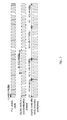
- FIG. 9 shows a diagram of a correspondence between a pseudo-random sequence and clock frequency
- FIG. 10 shows a schematic diagram of a clock frequency modulation apparatus according to an embodiment of the present invention.
- FIG. 11 shows a diagram of an implementation effect of a clock frequency modulation method according to an embodiment of the present invention.
- an interfering signal or a harmonic derived from the interfering signal falls within a band of a radio frequency signal (in particular, energy of a received signal is usually very small), resulting in worsening of receiving sensitivity of the RF circuit, saturation of a receiving analog to digital converter (ADC, Analog to Digital Converter), or deterioration of an error vector magnitude (EVM, Error Vector Magnitude) of a signal evaluation module, so that an indicator requirement in a protocol cannot be met.
- ADC Analog to Digital Converter
- EVM Error Vector Magnitude
- a clock frequency of a digital circuit of a ROC is fixed, and an introduced interference is a high-energy monophonic signal. If the clock frequency of the digital circuit jitters randomly within a specific range, the clock frequency is changed from a monophonic signal to a broadband signal.
- interfering energy of the broadband signal is greatly reduced compared with interfering energy of the monophonic signal.
- the clock frequency is a monophonic signal
- interference is also a monophonic signal
- the clock frequency is a broadband signal
- the interference is a broadband signal
- an interfering harmonic of order-n extends very wide, so that most interfering energy falls outside a band of an effective communication signal.
- an interference suppression effect of a high frequency band is better than an interference suppression effect of a low frequency band.
- FIG. 1 shows a clock frequency modulation method according to an embodiment of the present invention.
- N digital clocks according to a first digital clock of a system, where the N digital clocks include a second digital clock and N-1 digital clocks except the second digital clock, and a sum of frequency ratios of the first digital clock to each of the N-1 digital clocks is equal to N-1 times a frequency ratio of the first digital clock to the second digital clock, where N is an integer greater than 2.
- a clock frequency modulation technology that is, clock spread spectrum
- a clock frequency modulation technology that is, clock spread spectrum
- the second digital clock may be called a center-point digital clock of the system, which represents a digital clock that is expected to be obtained through fitting by means of clock frequency modulation processing, and may also be called “a pre-modulation digital clock” or “a digital clock in a non-modulation domain” in this embodiment of the present invention.
- the first digital clock may be a current phase locked loop (PLL, Phase Locked Loop) output clock of the system.
- PLL Phase Locked Loop
- a specific type of the digital clock is not limited in this embodiment of the present invention, and the digital clock may also be another digital clock of the system.
- the N digital clocks may separately be integer frequency dividing clocks of the first digital clock, and frequency dividing coefficients of the N digital clocks are different from each other.
- the N digital clocks may be separately mapped to a pseudo-random noise (PN, Pseudo-random Noise) sequence with a length of M during the modulation period, so as to randomize frequency jitter of the N digital clocks, where a probability that each of the N digital clocks appears in the modulation period is equal, a cyclic period of the PN sequence is equal to the modulation period, N is less than or equal to 2 M , and M is a positive integer.
- the first digital clock may be fitted, during the modulation period by using the N digital clocks mapped to the PN sequence, into the periodic second digital clock.
- the N-1 digital clocks may be mapped to 2 M -1 cyclic states of the PN sequence in a one-to-one manner, and the second digital clock may be mapped to a dead state of the PN sequence, where the dead state is a PN code whose M bits are all 0s, and other PN codes are the cyclic states.
- L bits may be selected from M bits of the PN sequence, the second digital clock is mapped to a PN code, which is in the PN sequence, with the L bits whose numerical values are all 0s, and the N-1 digital clocks are mapped to other PN codes of the PN sequence, where any of the digital clocks is separately mapped to a plurality of PN codes with the L bits whose numerical values are the same.
- an interfering harmonic is an order-n interfering harmonic of the N digital clocks
- a bandwidth of the order-n interfering harmonic is n times a bandwidth of the N modulated digital clocks, so that interfering energy of the interfering harmonic is greatly reduced.
- the modulation period may be equal to a cyclic period of the PN sequence, and the modulation period may also be called a random seed period.
- the first digital clock is a PLL output clock and its frequency C is 983.04 MHz
- a frequency B, which is expected to be obtained, of the second digital clock (which may be called “a pre-modulation digital clock” or “a digital clock in a non-modulation domain”) is 122.88 MHz.
- a sequence of the four types of digital clocks A 0 -A 3 shown in FIG. 2 is just exemplary, this embodiment of the present invention does not set a limitation to a manner of sorting the digital clocks, and it is only required that a probability that each digital clock except the second digital clock B appears is equal.
- the digital clocks may be randomly arranged, or may be arranged in a particular order. These changes all fall within the scope of the present invention.
- a highest clock frequency (which is 163.84 MHz in this embodiment) meets a timing convergence constraint, so that each designed timing indicator can meet a requirement formulated before designing;
- a quantity of selected digital clock frequencies is a power of 2, and one of the frequencies is a frequency (which is 122.88 MHz in this embodiment) of the pre-modulation digital clock.
- a PN sequence which will be described in detail in the following content.
- a sequence of the selected digital clock frequencies is ⁇ A 0 , A 1 , . . . , AN ⁇
- a frequency of the center-point digital clock is B (where B is one of ⁇ A 0 , A 1 , . . . , AN ⁇ )
- a frequency of the first digital clock is C.
- low-frequency digital clocks with a plurality of frequencies are generated by dividing a frequency of a high-frequency digital clock, and an output clock is randomly selected from these low frequency digital clocks.
- periodic frequency fitting of clock frequencies can be achieved within one period (which is generally a random seed period), that is, a digital circuit does not sense jitter or a change in clock frequencies in a specific period.
- first-in first-out (FIFO, First In First Out) processing is separately performed before N digital clocks are determined according to a current first digital clock, and after the first digital clock is separately modulated onto the N digital clocks and is output.
- first-in first-out (FIFO, First In First Out) processing is separately performed before S 11 .
- first FIFO buffering may be performed on the first digital clock; and after S 12 , second FIFO buffering may be performed on the N digital clocks, where the second FIFO buffering is synchronous with the first FIFO buffering, so that the N digital clocks have no delay jitter after modulation.
- a clock frequency modulation apparatus 30 includes a determining unit 31 and a modulation unit 32 .
- the determining unit 31 is configured to determine N digital clocks according to a first digital clock of a system, where the N digital clocks include a second digital clock and N-1 digital clocks except the second digital clock, and a sum of frequency ratios of the first digital clock to each of the N-1 digital clocks is equal to N-1 times a frequency ratio of the first digital clock to the second digital clock, where N is an integer greater than 2.
- the modulation unit 32 is configured to fit, during a modulation period by using the N digital clocks, the first digital clock into the periodic second digital clock.
- a clock frequency modulation technology that is, clock spread spectrum
- a clock frequency modulation technology that is, clock spread spectrum
- the second digital clock may be called a center-point digital clock of the system, which represents a digital clock that is expected to be obtained through fitting by means of clock frequency modulation processing, and may also be called “a pre-modulation digital clock” or “a digital clock in a non-modulation domain” in this embodiment of the present invention.
- the first digital clock may be a current phase locked loop (PLL, Phase Locked Loop) output clock of the system.
- PLL Phase Locked Loop
- a specific type of the digital clock is not limited in this embodiment of the present invention, and the digital clock may also be another digital clock of the system.
- the N digital clocks may separately be integer frequency dividing clocks of the first digital clock, and frequency dividing coefficients of the N digital clocks are different from each other.
- the modulation unit 32 may include a mapping subunit 321 and a fitting subunit 322 , as shown in FIG. 4 .
- the mapping subunit 321 is configured to separately map the N digital clocks to a pseudo-random noise PN sequence with a length of M during the modulation period, so as to randomize frequency jitter of the N digital clocks, where a probability that each of the N digital clocks appears in the modulation period is equal, a cyclic period of the PN sequence is equal to the modulation period, N is less than or equal to 2 M , and M is a positive integer.
- the fitting subunit 322 is configured to fit, during the modulation period by using the N digital clocks mapped to the PN sequence, the periodic first digital clock into the periodic second digital clock.
- the mapping subunit 321 may be configured to map the N-1 digital clocks to 2 M -1 cyclic states of the PN sequence in a one-to-one manner, and map the second digital clock to a dead state of the PN sequence, where the dead state is a PN code whose M bits are all 0s, and other PN codes are the cyclic states.
- the mapping subunit 321 may be configured to, when N is equal to 2 L and L is a positive integer less than M, select L bits from M bits of the PN sequence, the second digital clock is mapped to a PN code, which is in the PN sequence, with the L bits whose numerical values are all 0s, and the N-1 clock frequencies are mapped to other PN codes of the PN sequence, where any of the digital clocks is separately mapped to a plurality of PN codes with the L bits whose numerical values are the same.
- the clock frequency modulation apparatus 30 may further include a first FIFO buffer 33 and a second FIFO buffer 34 , as shown in FIG. 5 .
- the first FIFO buffer 33 is connected to the determining unit 31 and configured to perform first FIFO buffering on the first digital clock before the first digital clock is input to the determining unit 31 .
- the second FIFO buffer 34 is connected to the modulation unit 32 and configured to perform second FIFO buffering on the N digital clocks output by the modulation unit 32 .
- the second FIFO buffering is synchronous with the first FIFO buffering, so that the N digital clocks have no delay jitter after modulation.
- the clock frequency modulation apparatus 30 can be implemented in a form of a chip or another circuit form; however, this embodiment of the present invention does not limit the specific implementation manner of the clock frequency modulation apparatus 30 .
- implementation of a PN4 algorithm in the embodiment with specific numerical values in FIG. 2 is still used as an example for description, that is, four digital clocks 163.84 MHz (which is a frequency obtained by dividing 983.04 MHz by 6), 140.43 MHz (which is a frequency obtained by dividing 983.04 MHz by 7), 122.88 MHz (which is a frequency obtained by dividing 983.04 MHz by 8), and 89.37 MHz (which is a frequency obtained by dividing 983.04 MHz by 11) are selected to fit into a periodical center-point digital clock.
- DPLL Digital Phase Locked Loop
- Counter Counter
- Gating Cell gating cell
- OR gate OR OR
- PN sequence generating circuit PN GEN PN sequence GEN
- the gating cell in FIG. 6 may implement a main function of the determining unit 31 in FIG. 3 , and the PN sequence generating circuit, the selector, the D flip-flop, the counter, the comparator, the OR gate, the gating cell, and the like in FIG. 6 can implement a main function of the modulation unit 32 in FIG. 3 , where the PN sequence generating circuit, the selector, and the like in FIG. 6 can implement a main function of the mapping subunit 321 in FIG. 4 , and the gating cell and the like can implement a main function of the fitting subunit 322 in FIG. 4 .
- a reference clock (REF_CLK) signal after being input to the DPLL circuit, becomes a DPLL_CLK signal, where the DPLL_CLK signal is a high-frequency clock signal and used as an example of the foregoing first digital clock signal.
- the counter uses the DPLL_CLK signal as triggered input for counting, and outputs a counting result.
- a PN sequence generated by the PN sequence generating circuit is input to the selector, and input of the selector is a dividing coefficient (that is, frequency ratios of the first digital clock signal to each signal of the N digital clocks) of a low-frequency digital clock used for fitting.
- a dividing coefficient that is, frequency ratios of the first digital clock signal to each signal of the N digital clocks
- a result that is obtained after output of the selector is processed by the D flip-flop is compared with a counting result output by the counter.
- a comparison result is input to the OR gate, and other input of the OR gate is a ⁇ clk_mod_en signal.
- the ⁇ clk_mod_en signal is an enabling signal for the clock frequency modulation.
- Output of the OR gate is used as input of the D flip-flop, the triggered input of the D flip-flop is a DPLL_CLK signal, the result obtained by the D flip-flop is output to the gating cell (en).
- the result obtained by the D flip-flop is an clock input enabling signal, for example, when en is 0, it indicates that a current clock edge is not output; when en is 1, it indicates that the current clock edge is output.
- the DPLL_CLK signal is also used as other input (in) of the gating cell, where a clock system CLK SYS signal output (out) by the gating cell is used as a clock input signal CLK of the PN GEN circuit.
- a clock system CLK SYS signal output (out) by the gating cell is used as a clock input signal CLK of the PN GEN circuit.
- the PN GEN circuit Under joint effects of signals INI_SET, PN_INI, CLK, and the like, the PN GEN circuit generates a PN sequence.
- the PN sequence is provided to the selector, so that the selector can improve randomicity of the four frequencies 163.84 MHz (which is a frequency obtained by dividing 983.04 MHz by 6), 140.43 MHz (which is a frequency obtained by dividing 983.04 MHz by 7), 122.88 MHz (which is a frequency obtained by dividing 983.04 MHz by 8), and 89.37 MHz (which is a frequency obtained by dividing 983.04 MHz by 11).
- the INI_SET signal is a command for setting an initial value of a PN
- the PN_INI signal is an initial value (a seed) of the PN.
- clock frequency modulation needs to use a PN sequence to randomize jitter of a clock frequency to a greatest extent after frequency modulation, so as to obtain a better interference suppression effect.
- the PN sequence generating circuit PN GEN corresponding to the PN 4 algorithm used in this specific embodiment is shown in FIG. 7 .
- FIG. 7 is an example of the PN generating (PN GEN) circuit shown in FIG. 6 .
- the PN generating circuit in FIG. 7 shows a structural diagram of performing periodic frequency fitting of the four frequencies, that is, the algorithm applied to PN 4.
- the PN generating circuit includes four pairs of selectors and D flip-flops, where each pair of selector and D flip-flop are connected in series with each other and forms a loop (Loop) by using a summator. In addition, in each pair of selector and D flip-flop, output of the selector is used as input of the D flip-flop.
- a structure of the PN GEN circuit is not unique, and a quantity of pairs of selector and D flip-flop may be changed according to a quantity of required corresponding frequencies. For example, if a modulated interfering harmonic clock frequency corresponding to periodic fitting of eight frequencies needs to be generated, eight pairs of selectors and D flip-flops may be set.
- an INI_SET signal is used to perform initial setting on four selectors (that is, a first selector S 1 , a second selector S 2 , a third selector S 3 , and a fourth selector).
- Output of the first selector S 1 after PN_INI [0] is input enters a first flip-flop D 1 , and the first flip-flop D 1 outputs PN [0] under triggering of a clock signal CLK.
- output of the second selector S 2 after PN [0] and PN_INI [1] are input enters a second flip-flop D 2 , and the second flip-flop D 2 outputs PN [1] under triggering of the clock signal CLK.
- a third selector S 3 after PN [1] and PN_INI [2] are input enters a third flip-flop D 3 , and the third flip-flop D 3 outputs PN [2] under triggering of the clock signal CLK.
- output of a fourth selector S 4 after PN and PN_INI [3] are input enters a fourth flip-flop D 4 , and the fourth selector D 4 outputs PN [3] under triggering of the clock signal CLK.
- a result obtained when PN [3] and PN [0] are added by a summator is input together with PN_INI [0] to the first selector S 1 , and this is circulated repeatedly.
- the INI_SET signal is a command for setting an initial value of a PN
- the PN_INI signal is an initial value (a seed) of a PN
- the PN signal is output of a PN sequence.
- FIG. 8 shows a diagram of state transfer of a PN sequence that may be generated by a PN GEN circuit, where 15 cyclic states and a dead state “0000” are included.
- a longer PN sequence has better randomicity, but a longer PN sequence requires a longer period of frequency fitting, and a frequency difference becomes greater after it accumulates for some time, which results in more resources required before and after FIFO. Therefore, a PN sequence of a proper length may be selected in combination with randomicity that needs to be achieved.
- a length of the PN sequence is m, only a maximum of 2 M -1 frequencies can be selected for clock frequency modulation.
- the PN sequence is not mapped in a one-to-one manner to the clock frequencies (if there are 15 frequencies, one-to-one mapping can be implemented; otherwise, only a part of the sequence is selected for mapping, where in an optional embodiment, two significant bits are selected from a 4-bit PN code as the PN sequence, as shown in FIG.
- a quantity of cyclic states is not 2 M , it is preferable to map a non-modulated frequency (which is, for example, 122.88 MHz in this specific embodiment) to a dead state (that is “0000”); otherwise, probabilities that the modulated frequencies appear are inconsistent, and periodic frequency fitting cannot be implemented.
- a non-modulated frequency which is, for example, 122.88 MHz in this specific embodiment
- frequency modulation and periodic frequency fitting are achieved by using a dynamic clock gating (Clock Gating) circuit.
- clock frequency jitter may bring about the following problems:
- Radio communications is relatively sensitive to experimental certainty, so it is required that there is no signal delay jitter from the external perspective.
- this specific embodiment may further use synchronous FIFO for buffering, so as to absorb this kind of periodic frequency jitter, so that the two foregoing problems can be avoided.
- a specific circuit structure is shown in FIG. 10 .
- FIG. 11 shows a diagram of an effect of using the clock frequency modulation method according to the embodiment of the present invention.
- an order-6 interfering harmonic falls in a signal band (Band 12 ).
- Band 12 a signal band
- effective digital-analog interference suppression is achieved. It is easy for a person skilled in the art to understand that if more effective digital-analog interference suppression is expected to be achieved, the number of frequencies may be increased, and a length of a PN sequence can be enlarged.
- the clock frequency modulation apparatus 30 is not necessarily only implemented by the clock gating cell circuit in the specific embodiment, and the PN sequence generating circuit is not just as shown in FIG. 7 . Any circuit that can implement randomicity required in periodic frequency fitting and spread spectrum may be used to implement the clock frequency modulation apparatus 30 in this embodiment of the present invention.
- the disclosed system, apparatus, and method may be implemented in other manners.
- the described apparatus embodiment is merely exemplary.
- the unit division is merely logical function division, and there may be other division in actual implementation.
- a plurality of units or components may be combined or integrated into another system, or some features may be ignored or not performed.
- the displayed or discussed mutual couplings or direct couplings or communication connections may be implemented through some interfaces.
- the indirect couplings or communication connections between the apparatuses or units may be implemented in electronic, mechanical, or other forms.
- the units described as separate parts may or may not be physically separate, and parts displayed as units may or may not be physical units, may be located in one position, or may be distributed on a plurality of network units. A part or all of the units may be selected according to actual needs to achieve the objectives of the solutions of the embodiments.
- functional units in the embodiments of the present invention may be integrated into one processing unit, or each of the units may exist alone physically, or two or more units are integrated into one unit.
- the functions When the functions are implemented in the form of a software functional unit and sold or used as an independent product, the functions may be stored in a computer-readable storage medium. Based on such an understanding, the technical solutions of the present invention essentially, or the part contributing to the prior art, or a part of the technical solutions may be implemented in a form of a software product.
- the software product is stored in a storage medium, and includes several instructions for instructing a computer device (which may be a personal computer, a server, or a network device) to perform all or a part of the steps of the methods described in the embodiments of the present invention.
- the foregoing storage medium includes: any medium that can store program code, such as a USB flash drive, a removable hard disk, a read-only memory (ROM, Read-Only Memory), a random access memory (RAM, Random Access Memory), a magnetic disk, or an optical disc.
- program code such as a USB flash drive, a removable hard disk, a read-only memory (ROM, Read-Only Memory), a random access memory (RAM, Random Access Memory), a magnetic disk, or an optical disc.
Landscapes
- Engineering & Computer Science (AREA)
- Physics & Mathematics (AREA)
- Theoretical Computer Science (AREA)
- General Engineering & Computer Science (AREA)
- Power Engineering (AREA)
- General Physics & Mathematics (AREA)
- Nonlinear Science (AREA)
- Mathematical Physics (AREA)
- Computing Systems (AREA)
- Human Computer Interaction (AREA)
- Computer Hardware Design (AREA)
- Manipulation Of Pulses (AREA)
- Synchronisation In Digital Transmission Systems (AREA)
Applications Claiming Priority (3)
| Application Number | Priority Date | Filing Date | Title |
|---|---|---|---|
| CN201410168292.XA CN103955256B (zh) | 2014-04-24 | 2014-04-24 | 时钟频率调制的方法和时钟频率调制装置 |
| CN201410168292.X | 2014-04-24 | ||
| CN201410168292 | 2014-04-24 |
Publications (2)
| Publication Number | Publication Date |
|---|---|
| US20150311888A1 US20150311888A1 (en) | 2015-10-29 |
| US9525403B2 true US9525403B2 (en) | 2016-12-20 |
Family
ID=51332541
Family Applications (1)
| Application Number | Title | Priority Date | Filing Date |
|---|---|---|---|
| US14/693,522 Active 2035-04-24 US9525403B2 (en) | 2014-04-24 | 2015-04-22 | Clock frequency modulation method and clock frequency modulation apparatus |
Country Status (3)
| Country | Link |
|---|---|
| US (1) | US9525403B2 (ko) |
| EP (1) | EP2937999B1 (ko) |
| CN (1) | CN103955256B (ko) |
Families Citing this family (6)
| Publication number | Priority date | Publication date | Assignee | Title |
|---|---|---|---|---|
| CN103955256B (zh) * | 2014-04-24 | 2017-04-12 | 华为技术有限公司 | 时钟频率调制的方法和时钟频率调制装置 |
| CN106992770B (zh) * | 2016-01-21 | 2021-03-30 | 华为技术有限公司 | 时钟电路及其传输时钟信号的方法 |
| US9698781B1 (en) * | 2016-05-26 | 2017-07-04 | Intel Corporation | Dynamic clock gating frequency scaling |
| WO2020093271A1 (zh) * | 2018-11-07 | 2020-05-14 | 北京晶视智能科技有限公司 | 门控电路及门控方法 |
| CN113285695B (zh) * | 2021-07-26 | 2021-10-29 | 浙江芯昇电子技术有限公司 | 一种高频时钟调相电路及其实现方法 |
| CN114237020B (zh) | 2021-12-10 | 2023-09-26 | 合肥兆芯电子有限公司 | 计时器校准方法与电子装置 |
Citations (17)
| Publication number | Priority date | Publication date | Assignee | Title |
|---|---|---|---|---|
| US4849703A (en) | 1986-07-15 | 1989-07-18 | Hayes Microcomputer Products, Inc. | Method and apparatus for generating a data sampling clock locked to a baud clock contained in a data signal |
| US6397048B1 (en) * | 1998-07-21 | 2002-05-28 | Sharp Kabushiki Kaisha | Signal processing apparatus and communication apparatus |
| US6433643B1 (en) * | 2000-02-22 | 2002-08-13 | Rockwell Collins, Inc. | Reduced latency differentiator |
| WO2003067379A2 (en) | 2002-02-04 | 2003-08-14 | Xemi Inc. | Method and system of reducing electromagnetic interference emissions |
| CN1510861A (zh) | 2002-12-26 | 2004-07-07 | 华为技术有限公司 | 一种控制系统时钟频率的方法 |
| WO2005078608A2 (en) | 2004-02-13 | 2005-08-25 | Interuniversitair Microelektronica Centrum Vzw | A method and apparatus for minimising the influence of a digital sub-circuit on at least partially digital circuits |
| US20050216780A1 (en) * | 2004-03-29 | 2005-09-29 | Samsung Electronics Co., Ltd. | Clock signal generator circuit for serial bus communication |
| US7010287B2 (en) * | 2003-04-01 | 2006-03-07 | Samsung Electro-Mechanics Co., Ltd. | Quadrature signal generator with feedback type frequency doubler |
| US20060170465A1 (en) * | 2005-01-28 | 2006-08-03 | Kelley James W | Circuit for multiplying continuously varying signals |
| US7208990B1 (en) * | 2006-04-28 | 2007-04-24 | Giga-Tronics, Inc. | Low noise microwave frequency synthesizer having loop accumulation |
| CN101546206A (zh) | 2008-03-26 | 2009-09-30 | 刘伯安 | 一种频率动态可变的数字电路时钟源的实现方法 |
| CN101807913A (zh) | 2010-03-26 | 2010-08-18 | 华为技术有限公司 | 低速时钟使能信号产生方法、装置和设备 |
| US20110074469A1 (en) | 2009-09-30 | 2011-03-31 | Nokia Corporation | Frequency Generation Circuitry And Method |
| US20120081156A1 (en) * | 2010-09-30 | 2012-04-05 | Leonardus Hesen | High Speed RF Divider |
| CN102447472A (zh) | 2010-09-30 | 2012-05-09 | 上海贝尔股份有限公司 | 用于产生时钟信号的方法以及数控振荡器 |
| US20130301754A1 (en) | 2012-05-10 | 2013-11-14 | Robert Bogdan Staszewski | Frequency modulator having digitally-controlled oscillator arranged for receiving modulation tuning word and phase-locked loop tuning word and/or receiving fractional tuning word obtained through asynchronous sampling and integer tuning word |
| US20150311888A1 (en) * | 2014-04-24 | 2015-10-29 | Huawei Technologies Co., Ltd. | Clock frequency modulation method and clock frequency modulation apparatus |
-
2014
- 2014-04-24 CN CN201410168292.XA patent/CN103955256B/zh active Active
-
2015
- 2015-04-02 EP EP15162430.1A patent/EP2937999B1/en active Active
- 2015-04-22 US US14/693,522 patent/US9525403B2/en active Active
Patent Citations (17)
| Publication number | Priority date | Publication date | Assignee | Title |
|---|---|---|---|---|
| US4849703A (en) | 1986-07-15 | 1989-07-18 | Hayes Microcomputer Products, Inc. | Method and apparatus for generating a data sampling clock locked to a baud clock contained in a data signal |
| US6397048B1 (en) * | 1998-07-21 | 2002-05-28 | Sharp Kabushiki Kaisha | Signal processing apparatus and communication apparatus |
| US6433643B1 (en) * | 2000-02-22 | 2002-08-13 | Rockwell Collins, Inc. | Reduced latency differentiator |
| WO2003067379A2 (en) | 2002-02-04 | 2003-08-14 | Xemi Inc. | Method and system of reducing electromagnetic interference emissions |
| CN1510861A (zh) | 2002-12-26 | 2004-07-07 | 华为技术有限公司 | 一种控制系统时钟频率的方法 |
| US7010287B2 (en) * | 2003-04-01 | 2006-03-07 | Samsung Electro-Mechanics Co., Ltd. | Quadrature signal generator with feedback type frequency doubler |
| WO2005078608A2 (en) | 2004-02-13 | 2005-08-25 | Interuniversitair Microelektronica Centrum Vzw | A method and apparatus for minimising the influence of a digital sub-circuit on at least partially digital circuits |
| US20050216780A1 (en) * | 2004-03-29 | 2005-09-29 | Samsung Electronics Co., Ltd. | Clock signal generator circuit for serial bus communication |
| US20060170465A1 (en) * | 2005-01-28 | 2006-08-03 | Kelley James W | Circuit for multiplying continuously varying signals |
| US7208990B1 (en) * | 2006-04-28 | 2007-04-24 | Giga-Tronics, Inc. | Low noise microwave frequency synthesizer having loop accumulation |
| CN101546206A (zh) | 2008-03-26 | 2009-09-30 | 刘伯安 | 一种频率动态可变的数字电路时钟源的实现方法 |
| US20110074469A1 (en) | 2009-09-30 | 2011-03-31 | Nokia Corporation | Frequency Generation Circuitry And Method |
| CN101807913A (zh) | 2010-03-26 | 2010-08-18 | 华为技术有限公司 | 低速时钟使能信号产生方法、装置和设备 |
| US20120081156A1 (en) * | 2010-09-30 | 2012-04-05 | Leonardus Hesen | High Speed RF Divider |
| CN102447472A (zh) | 2010-09-30 | 2012-05-09 | 上海贝尔股份有限公司 | 用于产生时钟信号的方法以及数控振荡器 |
| US20130301754A1 (en) | 2012-05-10 | 2013-11-14 | Robert Bogdan Staszewski | Frequency modulator having digitally-controlled oscillator arranged for receiving modulation tuning word and phase-locked loop tuning word and/or receiving fractional tuning word obtained through asynchronous sampling and integer tuning word |
| US20150311888A1 (en) * | 2014-04-24 | 2015-10-29 | Huawei Technologies Co., Ltd. | Clock frequency modulation method and clock frequency modulation apparatus |
Non-Patent Citations (1)
| Title |
|---|
| Mögel et al., "EMI Performance of Spread Spectrum Clock Signals with respect to the IF Bandwidth of the EMC Standard," Proceedings of the 2005 European Conference on Circuit Theory and Design, vol. 1, Institute of Electrical and Electronics Engineers, New York, New York (Aug. 28-Sep. 2, 2005). |
Also Published As
| Publication number | Publication date |
|---|---|
| CN103955256A (zh) | 2014-07-30 |
| CN103955256B (zh) | 2017-04-12 |
| EP2937999B1 (en) | 2017-09-13 |
| US20150311888A1 (en) | 2015-10-29 |
| EP2937999A1 (en) | 2015-10-28 |
Similar Documents
| Publication | Publication Date | Title |
|---|---|---|
| US9525403B2 (en) | Clock frequency modulation method and clock frequency modulation apparatus | |
| US8233579B2 (en) | Devices comprising delay line for applying variable delay to clock signal | |
| CN103929173B (zh) | 分频器和无线通信设备 | |
| Lee et al. | A low-jitter 5000ppm spread spectrum clock generator for multi-channel SATA transceiver in 0.18/spl mu/m CMOS | |
| CN104158515B (zh) | 一种自动同步的多通道并行存储dds信号发生器 | |
| CN110350912A (zh) | 时钟信号生成器、锁相环电路及操作方法和无线通信设备 | |
| CN104378112A (zh) | 用于生成相位调制信号的数字时间转换器和方法 | |
| US8723577B2 (en) | Spreading a clock signal | |
| US11683048B2 (en) | Systems for and methods of fractional frequency division | |
| US9571083B2 (en) | All-digital delay-locked loop tuning method with randomized LSB-tuning | |
| WO2019067194A9 (en) | Serializer/deserializer (serdes) lanes with lane-by-lane datarate independence | |
| CN113204514A (zh) | 一种提高芯片的spi接口频率的方法 | |
| US20250007525A1 (en) | Clock Synchronization System and Method | |
| CN104135286B (zh) | 数字频率合成器及其数字频率合成方法 | |
| US10341082B1 (en) | Delay modulated clock division | |
| JP2012147080A (ja) | デルタシグマ変調型分数分周pll周波数シンセサイザおよびそれを備えた無線通信装置 | |
| CN102377413B (zh) | 展频时钟系统及其展频时钟产生器 | |
| US20180358958A1 (en) | Digital Controlled Oscillator Based Clock Generator For Multi-Channel Design | |
| JP5358676B2 (ja) | フィルタ回路、送信フィルタ回路、半導体集積回路及び通信機器並びにフィルタ回路のタイミング調整方法 | |
| US8405536B2 (en) | Communication system for frequency shift keying signal | |
| KR101206146B1 (ko) | 직렬 변환기 및 직렬 변환 방법 | |
| EP3868024A1 (en) | Downconversion using digital carrier signals | |
| US20160315621A1 (en) | Asynchronous high-speed programmable divider | |
| US10305493B2 (en) | Phase-locked loop and frequency synthesizer |
Legal Events
| Date | Code | Title | Description |
|---|---|---|---|
| AS | Assignment |
Owner name: HUAWEI TECHNOLOGIES CO., LTD., CHINA Free format text: ASSIGNMENT OF ASSIGNORS INTEREST;ASSIGNOR:HU, MINJIE;REEL/FRAME:035472/0945 Effective date: 20150416 |
|
| STCF | Information on status: patent grant |
Free format text: PATENTED CASE |
|
| MAFP | Maintenance fee payment |
Free format text: PAYMENT OF MAINTENANCE FEE, 4TH YEAR, LARGE ENTITY (ORIGINAL EVENT CODE: M1551); ENTITY STATUS OF PATENT OWNER: LARGE ENTITY Year of fee payment: 4 |
|
| MAFP | Maintenance fee payment |
Free format text: PAYMENT OF MAINTENANCE FEE, 8TH YEAR, LARGE ENTITY (ORIGINAL EVENT CODE: M1552); ENTITY STATUS OF PATENT OWNER: LARGE ENTITY Year of fee payment: 8 |