US9525038B2 - Method for producing semiconductor device and semiconductor device - Google Patents
Method for producing semiconductor device and semiconductor device Download PDFInfo
- Publication number
- US9525038B2 US9525038B2 US14/793,108 US201514793108A US9525038B2 US 9525038 B2 US9525038 B2 US 9525038B2 US 201514793108 A US201514793108 A US 201514793108A US 9525038 B2 US9525038 B2 US 9525038B2
- Authority
- US
- United States
- Prior art keywords
- insulating film
- semiconductor layer
- fin
- shaped semiconductor
- pillar
- Prior art date
- Legal status (The legal status is an assumption and is not a legal conclusion. Google has not performed a legal analysis and makes no representation as to the accuracy of the status listed.)
- Active
Links
- 239000004065 semiconductor Substances 0.000 title claims abstract description 163
- 238000004519 manufacturing process Methods 0.000 title abstract description 52
- 239000000758 substrate Substances 0.000 claims abstract description 17
- 229910052751 metal Inorganic materials 0.000 claims description 28
- 239000002184 metal Substances 0.000 claims description 28
- 238000009792 diffusion process Methods 0.000 claims description 20
- 229910021420 polycrystalline silicon Inorganic materials 0.000 abstract description 36
- 229920005591 polysilicon Polymers 0.000 abstract description 36
- 238000000151 deposition Methods 0.000 abstract description 21
- 238000005530 etching Methods 0.000 abstract description 16
- 239000010410 layer Substances 0.000 description 137
- XUIMIQQOPSSXEZ-UHFFFAOYSA-N Silicon Chemical compound [Si] XUIMIQQOPSSXEZ-UHFFFAOYSA-N 0.000 description 51
- 229910052710 silicon Inorganic materials 0.000 description 51
- 239000010703 silicon Substances 0.000 description 51
- 238000000034 method Methods 0.000 description 22
- 239000011229 interlayer Substances 0.000 description 7
- 238000005498 polishing Methods 0.000 description 6
- 239000000126 substance Substances 0.000 description 6
- 150000001875 compounds Chemical class 0.000 description 5
- 150000004767 nitrides Chemical class 0.000 description 5
- 230000003071 parasitic effect Effects 0.000 description 3
- ZOXJGFHDIHLPTG-UHFFFAOYSA-N Boron Chemical compound [B] ZOXJGFHDIHLPTG-UHFFFAOYSA-N 0.000 description 2
- OAICVXFJPJFONN-UHFFFAOYSA-N Phosphorus Chemical compound [P] OAICVXFJPJFONN-UHFFFAOYSA-N 0.000 description 2
- 229910052785 arsenic Inorganic materials 0.000 description 2
- RQNWIZPPADIBDY-UHFFFAOYSA-N arsenic atom Chemical compound [As] RQNWIZPPADIBDY-UHFFFAOYSA-N 0.000 description 2
- 229910052796 boron Inorganic materials 0.000 description 2
- 230000003247 decreasing effect Effects 0.000 description 2
- 239000012535 impurity Substances 0.000 description 2
- 230000010354 integration Effects 0.000 description 2
- 229910052698 phosphorus Inorganic materials 0.000 description 2
- 239000011574 phosphorus Substances 0.000 description 2
- POFVJRKJJBFPII-UHFFFAOYSA-N N-cyclopentyl-5-[2-[[5-[(4-ethylpiperazin-1-yl)methyl]pyridin-2-yl]amino]-5-fluoropyrimidin-4-yl]-4-methyl-1,3-thiazol-2-amine Chemical compound C1(CCCC1)NC=1SC(=C(N=1)C)C1=NC(=NC=C1F)NC1=NC=C(C=C1)CN1CCN(CC1)CC POFVJRKJJBFPII-UHFFFAOYSA-N 0.000 description 1
- 238000005229 chemical vapour deposition Methods 0.000 description 1
- 238000004518 low pressure chemical vapour deposition Methods 0.000 description 1
- 238000012986 modification Methods 0.000 description 1
- 230000004048 modification Effects 0.000 description 1
Images


Classifications
-
- H—ELECTRICITY
- H01—ELECTRIC ELEMENTS
- H01L—SEMICONDUCTOR DEVICES NOT COVERED BY CLASS H10
- H01L29/00—Semiconductor devices specially adapted for rectifying, amplifying, oscillating or switching and having potential barriers; Capacitors or resistors having potential barriers, e.g. a PN-junction depletion layer or carrier concentration layer; Details of semiconductor bodies or of electrodes thereof ; Multistep manufacturing processes therefor
- H01L29/40—Electrodes ; Multistep manufacturing processes therefor
- H01L29/41—Electrodes ; Multistep manufacturing processes therefor characterised by their shape, relative sizes or dispositions
- H01L29/423—Electrodes ; Multistep manufacturing processes therefor characterised by their shape, relative sizes or dispositions not carrying the current to be rectified, amplified or switched
- H01L29/42312—Gate electrodes for field effect devices
- H01L29/42316—Gate electrodes for field effect devices for field-effect transistors
- H01L29/4232—Gate electrodes for field effect devices for field-effect transistors with insulated gate
- H01L29/42384—Gate electrodes for field effect devices for field-effect transistors with insulated gate for thin film field effect transistors, e.g. characterised by the thickness or the shape of the insulator or the dimensions, the shape or the lay-out of the conductor
- H01L29/42392—Gate electrodes for field effect devices for field-effect transistors with insulated gate for thin film field effect transistors, e.g. characterised by the thickness or the shape of the insulator or the dimensions, the shape or the lay-out of the conductor fully surrounding the channel, e.g. gate-all-around
-
- H—ELECTRICITY
- H01—ELECTRIC ELEMENTS
- H01L—SEMICONDUCTOR DEVICES NOT COVERED BY CLASS H10
- H01L21/00—Processes or apparatus adapted for the manufacture or treatment of semiconductor or solid state devices or of parts thereof
- H01L21/02—Manufacture or treatment of semiconductor devices or of parts thereof
- H01L21/04—Manufacture or treatment of semiconductor devices or of parts thereof the devices having potential barriers, e.g. a PN junction, depletion layer or carrier concentration layer
- H01L21/18—Manufacture or treatment of semiconductor devices or of parts thereof the devices having potential barriers, e.g. a PN junction, depletion layer or carrier concentration layer the devices having semiconductor bodies comprising elements of Group IV of the Periodic Table or AIIIBV compounds with or without impurities, e.g. doping materials
- H01L21/28—Manufacture of electrodes on semiconductor bodies using processes or apparatus not provided for in groups H01L21/20 - H01L21/268
- H01L21/28008—Making conductor-insulator-semiconductor electrodes
- H01L21/28017—Making conductor-insulator-semiconductor electrodes the insulator being formed after the semiconductor body, the semiconductor being silicon
- H01L21/28026—Making conductor-insulator-semiconductor electrodes the insulator being formed after the semiconductor body, the semiconductor being silicon characterised by the conductor
- H01L21/28114—Making conductor-insulator-semiconductor electrodes the insulator being formed after the semiconductor body, the semiconductor being silicon characterised by the conductor characterised by the sectional shape, e.g. T, inverted-T
-
- H—ELECTRICITY
- H01—ELECTRIC ELEMENTS
- H01L—SEMICONDUCTOR DEVICES NOT COVERED BY CLASS H10
- H01L29/00—Semiconductor devices specially adapted for rectifying, amplifying, oscillating or switching and having potential barriers; Capacitors or resistors having potential barriers, e.g. a PN-junction depletion layer or carrier concentration layer; Details of semiconductor bodies or of electrodes thereof ; Multistep manufacturing processes therefor
- H01L29/40—Electrodes ; Multistep manufacturing processes therefor
- H01L29/41—Electrodes ; Multistep manufacturing processes therefor characterised by their shape, relative sizes or dispositions
- H01L29/423—Electrodes ; Multistep manufacturing processes therefor characterised by their shape, relative sizes or dispositions not carrying the current to be rectified, amplified or switched
- H01L29/42312—Gate electrodes for field effect devices
- H01L29/42316—Gate electrodes for field effect devices for field-effect transistors
- H01L29/4232—Gate electrodes for field effect devices for field-effect transistors with insulated gate
- H01L29/42356—Disposition, e.g. buried gate electrode
-
- H—ELECTRICITY
- H01—ELECTRIC ELEMENTS
- H01L—SEMICONDUCTOR DEVICES NOT COVERED BY CLASS H10
- H01L29/00—Semiconductor devices specially adapted for rectifying, amplifying, oscillating or switching and having potential barriers; Capacitors or resistors having potential barriers, e.g. a PN-junction depletion layer or carrier concentration layer; Details of semiconductor bodies or of electrodes thereof ; Multistep manufacturing processes therefor
- H01L29/40—Electrodes ; Multistep manufacturing processes therefor
- H01L29/41—Electrodes ; Multistep manufacturing processes therefor characterised by their shape, relative sizes or dispositions
- H01L29/423—Electrodes ; Multistep manufacturing processes therefor characterised by their shape, relative sizes or dispositions not carrying the current to be rectified, amplified or switched
- H01L29/42312—Gate electrodes for field effect devices
- H01L29/42316—Gate electrodes for field effect devices for field-effect transistors
- H01L29/4232—Gate electrodes for field effect devices for field-effect transistors with insulated gate
- H01L29/42364—Gate electrodes for field effect devices for field-effect transistors with insulated gate characterised by the insulating layer, e.g. thickness or uniformity
-
- H—ELECTRICITY
- H01—ELECTRIC ELEMENTS
- H01L—SEMICONDUCTOR DEVICES NOT COVERED BY CLASS H10
- H01L29/00—Semiconductor devices specially adapted for rectifying, amplifying, oscillating or switching and having potential barriers; Capacitors or resistors having potential barriers, e.g. a PN-junction depletion layer or carrier concentration layer; Details of semiconductor bodies or of electrodes thereof ; Multistep manufacturing processes therefor
- H01L29/66—Types of semiconductor device ; Multistep manufacturing processes therefor
- H01L29/66007—Multistep manufacturing processes
- H01L29/66075—Multistep manufacturing processes of devices having semiconductor bodies comprising group 14 or group 13/15 materials
- H01L29/66227—Multistep manufacturing processes of devices having semiconductor bodies comprising group 14 or group 13/15 materials the devices being controllable only by the electric current supplied or the electric potential applied, to an electrode which does not carry the current to be rectified, amplified or switched, e.g. three-terminal devices
- H01L29/66409—Unipolar field-effect transistors
- H01L29/66477—Unipolar field-effect transistors with an insulated gate, i.e. MISFET
- H01L29/6653—Unipolar field-effect transistors with an insulated gate, i.e. MISFET using the removal of at least part of spacer, e.g. disposable spacer
-
- H—ELECTRICITY
- H01—ELECTRIC ELEMENTS
- H01L—SEMICONDUCTOR DEVICES NOT COVERED BY CLASS H10
- H01L29/00—Semiconductor devices specially adapted for rectifying, amplifying, oscillating or switching and having potential barriers; Capacitors or resistors having potential barriers, e.g. a PN-junction depletion layer or carrier concentration layer; Details of semiconductor bodies or of electrodes thereof ; Multistep manufacturing processes therefor
- H01L29/66—Types of semiconductor device ; Multistep manufacturing processes therefor
- H01L29/66007—Multistep manufacturing processes
- H01L29/66075—Multistep manufacturing processes of devices having semiconductor bodies comprising group 14 or group 13/15 materials
- H01L29/66227—Multistep manufacturing processes of devices having semiconductor bodies comprising group 14 or group 13/15 materials the devices being controllable only by the electric current supplied or the electric potential applied, to an electrode which does not carry the current to be rectified, amplified or switched, e.g. three-terminal devices
- H01L29/66409—Unipolar field-effect transistors
- H01L29/66477—Unipolar field-effect transistors with an insulated gate, i.e. MISFET
- H01L29/66545—Unipolar field-effect transistors with an insulated gate, i.e. MISFET using a dummy, i.e. replacement gate in a process wherein at least a part of the final gate is self aligned to the dummy gate
-
- H—ELECTRICITY
- H01—ELECTRIC ELEMENTS
- H01L—SEMICONDUCTOR DEVICES NOT COVERED BY CLASS H10
- H01L29/00—Semiconductor devices specially adapted for rectifying, amplifying, oscillating or switching and having potential barriers; Capacitors or resistors having potential barriers, e.g. a PN-junction depletion layer or carrier concentration layer; Details of semiconductor bodies or of electrodes thereof ; Multistep manufacturing processes therefor
- H01L29/66—Types of semiconductor device ; Multistep manufacturing processes therefor
- H01L29/66007—Multistep manufacturing processes
- H01L29/66075—Multistep manufacturing processes of devices having semiconductor bodies comprising group 14 or group 13/15 materials
- H01L29/66227—Multistep manufacturing processes of devices having semiconductor bodies comprising group 14 or group 13/15 materials the devices being controllable only by the electric current supplied or the electric potential applied, to an electrode which does not carry the current to be rectified, amplified or switched, e.g. three-terminal devices
- H01L29/66409—Unipolar field-effect transistors
- H01L29/66477—Unipolar field-effect transistors with an insulated gate, i.e. MISFET
- H01L29/66666—Vertical transistors
-
- H—ELECTRICITY
- H01—ELECTRIC ELEMENTS
- H01L—SEMICONDUCTOR DEVICES NOT COVERED BY CLASS H10
- H01L29/00—Semiconductor devices specially adapted for rectifying, amplifying, oscillating or switching and having potential barriers; Capacitors or resistors having potential barriers, e.g. a PN-junction depletion layer or carrier concentration layer; Details of semiconductor bodies or of electrodes thereof ; Multistep manufacturing processes therefor
- H01L29/66—Types of semiconductor device ; Multistep manufacturing processes therefor
- H01L29/66007—Multistep manufacturing processes
- H01L29/66075—Multistep manufacturing processes of devices having semiconductor bodies comprising group 14 or group 13/15 materials
- H01L29/66227—Multistep manufacturing processes of devices having semiconductor bodies comprising group 14 or group 13/15 materials the devices being controllable only by the electric current supplied or the electric potential applied, to an electrode which does not carry the current to be rectified, amplified or switched, e.g. three-terminal devices
- H01L29/66409—Unipolar field-effect transistors
- H01L29/66477—Unipolar field-effect transistors with an insulated gate, i.e. MISFET
- H01L29/66742—Thin film unipolar transistors
-
- H—ELECTRICITY
- H01—ELECTRIC ELEMENTS
- H01L—SEMICONDUCTOR DEVICES NOT COVERED BY CLASS H10
- H01L29/00—Semiconductor devices specially adapted for rectifying, amplifying, oscillating or switching and having potential barriers; Capacitors or resistors having potential barriers, e.g. a PN-junction depletion layer or carrier concentration layer; Details of semiconductor bodies or of electrodes thereof ; Multistep manufacturing processes therefor
- H01L29/66—Types of semiconductor device ; Multistep manufacturing processes therefor
- H01L29/66007—Multistep manufacturing processes
- H01L29/66075—Multistep manufacturing processes of devices having semiconductor bodies comprising group 14 or group 13/15 materials
- H01L29/66227—Multistep manufacturing processes of devices having semiconductor bodies comprising group 14 or group 13/15 materials the devices being controllable only by the electric current supplied or the electric potential applied, to an electrode which does not carry the current to be rectified, amplified or switched, e.g. three-terminal devices
- H01L29/66409—Unipolar field-effect transistors
- H01L29/66477—Unipolar field-effect transistors with an insulated gate, i.e. MISFET
- H01L29/66787—Unipolar field-effect transistors with an insulated gate, i.e. MISFET with a gate at the side of the channel
- H01L29/66795—Unipolar field-effect transistors with an insulated gate, i.e. MISFET with a gate at the side of the channel with a horizontal current flow in a vertical sidewall of a semiconductor body, e.g. FinFET, MuGFET
-
- H—ELECTRICITY
- H01—ELECTRIC ELEMENTS
- H01L—SEMICONDUCTOR DEVICES NOT COVERED BY CLASS H10
- H01L29/00—Semiconductor devices specially adapted for rectifying, amplifying, oscillating or switching and having potential barriers; Capacitors or resistors having potential barriers, e.g. a PN-junction depletion layer or carrier concentration layer; Details of semiconductor bodies or of electrodes thereof ; Multistep manufacturing processes therefor
- H01L29/66—Types of semiconductor device ; Multistep manufacturing processes therefor
- H01L29/68—Types of semiconductor device ; Multistep manufacturing processes therefor controllable by only the electric current supplied, or only the electric potential applied, to an electrode which does not carry the current to be rectified, amplified or switched
- H01L29/76—Unipolar devices, e.g. field effect transistors
- H01L29/772—Field effect transistors
- H01L29/78—Field effect transistors with field effect produced by an insulated gate
- H01L29/7827—Vertical transistors
-
- H—ELECTRICITY
- H01—ELECTRIC ELEMENTS
- H01L—SEMICONDUCTOR DEVICES NOT COVERED BY CLASS H10
- H01L29/00—Semiconductor devices specially adapted for rectifying, amplifying, oscillating or switching and having potential barriers; Capacitors or resistors having potential barriers, e.g. a PN-junction depletion layer or carrier concentration layer; Details of semiconductor bodies or of electrodes thereof ; Multistep manufacturing processes therefor
- H01L29/66—Types of semiconductor device ; Multistep manufacturing processes therefor
- H01L29/68—Types of semiconductor device ; Multistep manufacturing processes therefor controllable by only the electric current supplied, or only the electric potential applied, to an electrode which does not carry the current to be rectified, amplified or switched
- H01L29/76—Unipolar devices, e.g. field effect transistors
- H01L29/772—Field effect transistors
- H01L29/78—Field effect transistors with field effect produced by an insulated gate
- H01L29/785—Field effect transistors with field effect produced by an insulated gate having a channel with a horizontal current flow in a vertical sidewall of a semiconductor body, e.g. FinFET, MuGFET
-
- H—ELECTRICITY
- H01—ELECTRIC ELEMENTS
- H01L—SEMICONDUCTOR DEVICES NOT COVERED BY CLASS H10
- H01L29/00—Semiconductor devices specially adapted for rectifying, amplifying, oscillating or switching and having potential barriers; Capacitors or resistors having potential barriers, e.g. a PN-junction depletion layer or carrier concentration layer; Details of semiconductor bodies or of electrodes thereof ; Multistep manufacturing processes therefor
- H01L29/66—Types of semiconductor device ; Multistep manufacturing processes therefor
- H01L29/68—Types of semiconductor device ; Multistep manufacturing processes therefor controllable by only the electric current supplied, or only the electric potential applied, to an electrode which does not carry the current to be rectified, amplified or switched
- H01L29/76—Unipolar devices, e.g. field effect transistors
- H01L29/772—Field effect transistors
- H01L29/78—Field effect transistors with field effect produced by an insulated gate
- H01L29/786—Thin film transistors, i.e. transistors with a channel being at least partly a thin film
- H01L29/78606—Thin film transistors, i.e. transistors with a channel being at least partly a thin film with supplementary region or layer in the thin film or in the insulated bulk substrate supporting it for controlling or increasing the safety of the device
- H01L29/78618—Thin film transistors, i.e. transistors with a channel being at least partly a thin film with supplementary region or layer in the thin film or in the insulated bulk substrate supporting it for controlling or increasing the safety of the device characterised by the drain or the source properties, e.g. the doping structure, the composition, the sectional shape or the contact structure
-
- H—ELECTRICITY
- H01—ELECTRIC ELEMENTS
- H01L—SEMICONDUCTOR DEVICES NOT COVERED BY CLASS H10
- H01L29/00—Semiconductor devices specially adapted for rectifying, amplifying, oscillating or switching and having potential barriers; Capacitors or resistors having potential barriers, e.g. a PN-junction depletion layer or carrier concentration layer; Details of semiconductor bodies or of electrodes thereof ; Multistep manufacturing processes therefor
- H01L29/66—Types of semiconductor device ; Multistep manufacturing processes therefor
- H01L29/68—Types of semiconductor device ; Multistep manufacturing processes therefor controllable by only the electric current supplied, or only the electric potential applied, to an electrode which does not carry the current to be rectified, amplified or switched
- H01L29/76—Unipolar devices, e.g. field effect transistors
- H01L29/772—Field effect transistors
- H01L29/78—Field effect transistors with field effect produced by an insulated gate
- H01L29/786—Thin film transistors, i.e. transistors with a channel being at least partly a thin film
- H01L29/78642—Vertical transistors
-
- H—ELECTRICITY
- H01—ELECTRIC ELEMENTS
- H01L—SEMICONDUCTOR DEVICES NOT COVERED BY CLASS H10
- H01L29/00—Semiconductor devices specially adapted for rectifying, amplifying, oscillating or switching and having potential barriers; Capacitors or resistors having potential barriers, e.g. a PN-junction depletion layer or carrier concentration layer; Details of semiconductor bodies or of electrodes thereof ; Multistep manufacturing processes therefor
- H01L29/66—Types of semiconductor device ; Multistep manufacturing processes therefor
- H01L29/68—Types of semiconductor device ; Multistep manufacturing processes therefor controllable by only the electric current supplied, or only the electric potential applied, to an electrode which does not carry the current to be rectified, amplified or switched
- H01L29/76—Unipolar devices, e.g. field effect transistors
- H01L29/772—Field effect transistors
- H01L29/78—Field effect transistors with field effect produced by an insulated gate
- H01L29/786—Thin film transistors, i.e. transistors with a channel being at least partly a thin film
- H01L29/78651—Silicon transistors
- H01L29/78654—Monocrystalline silicon transistors
-
- H—ELECTRICITY
- H01—ELECTRIC ELEMENTS
- H01L—SEMICONDUCTOR DEVICES NOT COVERED BY CLASS H10
- H01L29/00—Semiconductor devices specially adapted for rectifying, amplifying, oscillating or switching and having potential barriers; Capacitors or resistors having potential barriers, e.g. a PN-junction depletion layer or carrier concentration layer; Details of semiconductor bodies or of electrodes thereof ; Multistep manufacturing processes therefor
- H01L29/66—Types of semiconductor device ; Multistep manufacturing processes therefor
- H01L29/68—Types of semiconductor device ; Multistep manufacturing processes therefor controllable by only the electric current supplied, or only the electric potential applied, to an electrode which does not carry the current to be rectified, amplified or switched
- H01L29/76—Unipolar devices, e.g. field effect transistors
- H01L29/772—Field effect transistors
- H01L29/78—Field effect transistors with field effect produced by an insulated gate
- H01L29/786—Thin film transistors, i.e. transistors with a channel being at least partly a thin film
- H01L29/78696—Thin film transistors, i.e. transistors with a channel being at least partly a thin film characterised by the structure of the channel, e.g. multichannel, transverse or longitudinal shape, length or width, doping structure, or the overlap or alignment between the channel and the gate, the source or the drain, or the contacting structure of the channel
-
- H—ELECTRICITY
- H01—ELECTRIC ELEMENTS
- H01L—SEMICONDUCTOR DEVICES NOT COVERED BY CLASS H10
- H01L29/00—Semiconductor devices specially adapted for rectifying, amplifying, oscillating or switching and having potential barriers; Capacitors or resistors having potential barriers, e.g. a PN-junction depletion layer or carrier concentration layer; Details of semiconductor bodies or of electrodes thereof ; Multistep manufacturing processes therefor
- H01L29/66—Types of semiconductor device ; Multistep manufacturing processes therefor
- H01L29/68—Types of semiconductor device ; Multistep manufacturing processes therefor controllable by only the electric current supplied, or only the electric potential applied, to an electrode which does not carry the current to be rectified, amplified or switched
- H01L29/76—Unipolar devices, e.g. field effect transistors
- H01L29/772—Field effect transistors
- H01L29/78—Field effect transistors with field effect produced by an insulated gate
- H01L29/785—Field effect transistors with field effect produced by an insulated gate having a channel with a horizontal current flow in a vertical sidewall of a semiconductor body, e.g. FinFET, MuGFET
- H01L2029/7858—Field effect transistors with field effect produced by an insulated gate having a channel with a horizontal current flow in a vertical sidewall of a semiconductor body, e.g. FinFET, MuGFET having contacts specially adapted to the FinFET geometry, e.g. wrap-around contacts
Definitions
- the present invention relates to a method for producing a semiconductor device and a semiconductor device.
- MOS transistors used therein have been miniaturized to a nanometer scale. Increasing miniaturization of MOS transistors renders it difficult to suppress leak current and a problem has arisen in which the area occupied by the circuit cannot be decreased while obtaining a required amount of current.
- SGT surrounding gate transistor
- a source, a gate, and a drain are arranged in a direction perpendicular to the substrate and a gate electrode surrounds a pillar-shaped semiconductor layer (for example, refer to Japanese Unexamined Patent Application Publication Nos. 2-71556, 2-188966, and 3-145761).
- a silicon pillar having a pillar-shaped nitride film hard mask is formed by using a mask for lithographically forming a silicon pillar, a planar silicon layer is formed at a bottom of the silicon pillar by using a mask for lithographically forming a planar silicon layer, and a gate line is formed by using a mask for lithographically forming a gate line (for example, refer to Japanese Unexamined Patent Application Publication No. 2009-182317).
- three masks are used to form a silicon pillar, a planar silicon layer, and a gate line.
- a metal-gate-last process in which a metal gate is formed after a high-temperature process has been employed in actual production of typical MOS transistors in order to integrate a metal gate process and a high-temperature process (refer to IEDM 2007, K. Mistry et. al, pp 247-250).
- a gate is formed by using polysilicon, an interlayer insulating film is deposited, the polysilicon gate is exposed by chemical mechanical polishing and etched, and then a metal is deposited.
- a metal-gate-last process in which a metal gate is formed after a high-temperature process must be employed in making SGTs in order to integrate a metal gate process and a high-temperature process.
- a first insulating film is used in a typical MOS transistor.
- a first insulating film is formed around one fin-shaped semiconductor layer, and etched back to expose the fin-shaped semiconductor layer and decrease the parasitic capacitance between the gate line and the substrate.
- a first insulating film must be used in order to decrease the parasitic capacitance between the gate line and the substrate. Since an SGT includes a pillar-shaped semiconductor layer in addition to a fin-shaped semiconductor layer, some consideration is necessary to form a pillar-shaped semiconductor layer.
- An object of the present invention is to provide a method for producing an SGT through a gate-last process in which two masks are used to form a fin-shaped semiconductor layer, a pillar-shaped semiconductor layer, a gate electrode, and a gate line, and an SGT structure obtained by the method.
- a first aspect of the invention provides a method for producing a semiconductor device.
- the method includes a first step of forming a fin-shaped semiconductor layer on a semiconductor substrate and forming a first insulating film around the fin-shaped semiconductor layer and a second step following the first step.
- the second step includes forming a second insulating film around the fin-shaped semiconductor layer, depositing a first polysilicon on the second insulating film to conduct planarization, forming a second resist for forming a gate line and a pillar-shaped semiconductor layer so that the second resist extends in a direction perpendicular to a direction in which the fin-shaped semiconductor layer extends, and etching the first polysilicon, the second insulating film, and the fin-shaped semiconductor layer to form a pillar-shaped semiconductor layer and a first dummy gate formed of the first polysilicon.
- the method may further include a third step following the second step, the third step including forming a fourth insulating film around the pillar-shaped semiconductor layer and the first dummy gate, depositing a second polysilicon around the fourth insulating film, and performing etching so that the second polysilicon remains on side walls of the first dummy gate and the pillar-shaped semiconductor layer and forms a second dummy gate.
- the third step may further include, after forming the fourth insulating film around the pillar-shaped semiconductor layer and the first dummy gate, forming a third resist, etching back the third resist to expose an upper portion of the pillar-shaped semiconductor layer, and forming a first diffusion layer in the upper portion of the pillar-shaped semiconductor layer.
- the method may further include a fourth step that includes forming a fifth insulating film around the second dummy gate, etching the fifth insulating film to have a side wall shape so as to form a side wall formed of the fifth insulating film, forming a second diffusion layer in an upper portion of the fin-shaped semiconductor layer and a lower portion of the pillar-shaped semiconductor layer, and forming a metal-semiconductor compound on the second diffusion layer.
- the method may further include a fifth step following the fourth step, the fifth step including depositing a contact stopper film, depositing an interlayer insulating film and performing chemical mechanical polishing to expose an upper portion of the second dummy gate and an upper portion of the first dummy gate, removing the second dummy gate and the first dummy gate, removing the second insulating film and the fourth insulating film, forming a gate insulating film around the pillar-shaped semiconductor layer and on inner sides of the fifth insulating film, depositing a metal, and performing etch-back to form a gate electrode and a gate line.
- the fifth step including depositing a contact stopper film, depositing an interlayer insulating film and performing chemical mechanical polishing to expose an upper portion of the second dummy gate and an upper portion of the first dummy gate, removing the second dummy gate and the first dummy gate, removing the second insulating film and the fourth insulating film, forming a gate insulating film around the pillar-shaped semiconductor layer
- a second aspect of the present invention provides a semiconductor device that includes a fin-shaped semiconductor layer disposed on a semiconductor substrate; a first insulating film disposed around the fin-shaped semiconductor layer; a pillar-shaped semiconductor layer disposed around the fin-shaped semiconductor layer; a gate insulating film disposed around the pillar-shaped semiconductor layer; a gate electrode formed of a metal and disposed around the gate insulating film; a gate line connected to the gate electrode and formed of a metal extending in a direction perpendicular to a direction in which the fin-shaped semiconductor layer extends; a first diffusion layer disposed in an upper portion of the pillar-shaped semiconductor layer; and a second diffusion layer disposed in an upper portion of the fin-shaped semiconductor layer and a lower portion of the pillar-shaped semiconductor layer.
- a width of the pillar-shaped semiconductor layer in a direction perpendicular to a direction in which the fin-shaped semiconductor layer extends is equal to a width of the fin-shaped semiconductor layer in the direction perpendicular to the direction in which the fin-shaped semiconductor layer extends.
- the gate insulating film is disposed around and at bottoms of gate electrode and the gate line, and an outer width of the gate electrode is equal to a width of the gate line.
- a method for producing an SGT through a gate-last process in which two masks are used to form a fin-shaped semiconductor layer, a pillar-shaped semiconductor layer, a gate electrode, and a gate line, and an SGT structure obtained by the method can be provided.
- the method includes a first step of forming a fin-shaped semiconductor layer on a semiconductor substrate and forming a first insulating film around the fin-shaped semiconductor layer; a second step following the first step and including forming a second insulating film around the fin-shaped semiconductor layer, depositing a first polysilicon on the second insulating film to conduct planarization, forming a second resist for forming a gate line and a pillar-shaped semiconductor layer so that the second resist extends in a direction perpendicular to a direction in which the fin-shaped semiconductor layer extends, and etching the first polysilicon, the second insulating film, and the fin-shaped semiconductor layer to form a pillar-shaped semiconductor layer and a first dummy gate formed of the first polysilicon; and a third step including forming a fourth insulating film around the pillar-shaped semiconductor layer and the first dummy gate, depositing a second polysilicon around the fourth insulating film, and performing etching so that the second polysilicon remains on side walls of
- an existing metal-gate-last production process which involves forming first and second dummy gates by using polysilicon, depositing an interlayer insulating film, exposing the first and second dummy gates by chemical mechanical polishing, etching the polysilicon gates, and then depositing metal, a metal gate SGT can be easily produced.
- FIG. 2A is a plan view related to a method for producing a semiconductor device according to an embodiment
- FIG. 2B is a cross-sectional view taken along line x-x′ in FIG. 2A
- FIG. 2C is a cross-sectional view taken along line y-y′ in FIG. 2A .
- FIG. 3A is a plan view related to the method for producing a semiconductor device according to an embodiment
- FIG. 3B is a cross-sectional view taken along line x-x′ in FIG. 3A
- FIG. 3C is a cross-sectional view taken along line y-y′ in FIG. 3A .
- FIG. 4A is a plan view related to the method for producing a semiconductor device according to an embodiment
- FIG. 4B is a cross-sectional view taken along line x-x′ in FIG. 4A
- FIG. 4C is a cross-sectional view taken along line y-y′ in FIG. 4A .
- FIG. 5A is a plan view related to the method for producing a semiconductor device according to an embodiment
- FIG. 5B is a cross-sectional view taken along line x-x′ in FIG. 5A
- FIG. 5C is a cross-sectional view taken along line y-y′ in FIG. 5A .
- FIG. 6A is a plan view related to the method for producing a semiconductor device according to an embodiment
- FIG. 6B is a cross-sectional view taken along line x-x′ in FIG. 6A
- FIG. 6C is a cross-sectional view taken along line y-y′ in FIG. 6A .
- FIG. 7A is a plan view related to the method for producing a semiconductor device according to an embodiment
- FIG. 7B is a cross-sectional view taken along line x-x′ in FIG. 7A
- FIG. 7C is a cross-sectional view taken along line y-y′ in FIG. 7A .
- FIG. 8A is a plan view related to the method for producing a semiconductor device according to an embodiment
- FIG. 8B is a cross-sectional view taken along line x-x′ in FIG. 8A
- FIG. 8C is a cross-sectional view taken along line y-y′ in FIG. 8A .
- FIG. 9A is a plan view related to the method for producing a semiconductor device according to an embodiment
- FIG. 9B is a cross-sectional view taken along line x-x′ in FIG. 9A
- FIG. 9C is a cross-sectional view taken along line y-y′ in FIG. 9A .
- FIG. 10A is a plan view related to the method for producing a semiconductor device according to an embodiment
- FIG. 10B is a cross-sectional view taken along line x-x′ in FIG. 10A
- FIG. 10C is a cross-sectional view taken along line y-y′ in FIG. 10A .
- FIG. 11A is a plan view related to the method for producing a semiconductor device according to an embodiment
- FIG. 11B is a cross-sectional view taken along line x-x′ in FIG. 11A
- FIG. 11C is a cross-sectional view taken along line y-y′ in FIG. 11A .
- FIG. 12A is a plan view related to the method for producing a semiconductor device according to an embodiment
- FIG. 12B is a cross-sectional view taken along line x-x′ in FIG. 12A
- FIG. 12C is a cross-sectional view taken along line y-y′ in FIG. 12A .
- FIG. 13A is a plan view related to the method for producing a semiconductor device according to an embodiment
- FIG. 13B is a cross-sectional view taken along line x-x′ in FIG. 13A
- FIG. 13C is a cross-sectional view taken along line y-y′ in FIG. 13A .
- FIG. 14A is a plan view related to the method for producing a semiconductor device according to an embodiment
- FIG. 14B is a cross-sectional view taken along line x-x′ in FIG. 14A
- FIG. 14C is a cross-sectional view taken along line y-y′ in FIG. 14A .
- FIG. 15A is a plan view related to the method for producing a semiconductor device according to an embodiment
- FIG. 15B is a cross-sectional view taken along line x-x′ in FIG. 15A
- FIG. 15C is a cross-sectional view taken along line y-y′ in FIG. 15A .
- FIG. 16A is a plan view related to the method for producing a semiconductor device according to an embodiment
- FIG. 1613 is a cross-sectional view taken along line x-x′ in FIG. 16A
- FIG. 16C is a cross-sectional view taken along line y-y′ in FIG. 16A .
- FIG. 17A is a plan view related to the method for producing a semiconductor device according to an embodiment
- FIG. 17B is a cross-sectional view taken along line x-x′ in FIG. 17A
- FIG. 17C is a cross-sectional view taken along line y-y′ in FIG. 17A .
- FIG. 18A is a plan view related to the method for producing a semiconductor device according to an embodiment
- FIG. 18B is a cross-sectional view taken along line x-x′ in FIG. 18A
- FIG. 18C is a cross-sectional view taken along line y-y′ in FIG. 18A .
- FIG. 19A is a plan view related to the method for producing a semiconductor device according to an embodiment
- FIG. 19B is a cross-sectional view taken along line x-x′ in FIG. 19A
- FIG. 19C is a cross-sectional view taken along line y-y′ in FIG. 19A .
- FIG. 20A is a plan view related to the method for producing a semiconductor device according to an embodiment
- FIG. 20B is a cross-sectional view taken along line x-x′ in FIG. 20A
- FIG. 20C is a cross-sectional view taken along line y-y′ in FIG. 20A .
- FIG. 21A is a plan view related to the method for producing a semiconductor device according to an embodiment
- FIG. 21B is a cross-sectional view taken along line x-x′ in FIG. 21A
- FIG. 21C is a cross-sectional view taken along line y-y′ in FIG. 21A .
- FIG. 22A is a plan view related to the method for producing a semiconductor device according to an embodiment
- FIG. 22B is a cross-sectional view taken along line x-x′ in FIG. 22A
- FIG. 22C is a cross-sectional view taken along line y-y′ in FIG. 22A .
- FIG. 23A is a plan view related to the method for producing a semiconductor device according to an embodiment
- FIG. 23B is a cross-sectional view taken along line x-x′ in FIG. 23A
- FIG. 23C is a cross-sectional view taken along line y-y′ in FIG. 23A .
- FIG. 24A is a plan view related to the method for producing a semiconductor device according to an embodiment
- FIG. 24B is a cross-sectional view taken along line x-x′ in FIG. 24A
- FIG. 24C is a cross-sectional view taken along line y-y′ in FIG. 24A .
- FIG. 25A is a plan view related to the method for producing a semiconductor device according to an embodiment
- FIG. 25B is a cross-sectional view taken along line x-x′ in FIG. 25A
- FIG. 25C is a cross-sectional view taken along line y-y′ in FIG. 25A .
- FIG. 26A is a plan view related to the method for producing a semiconductor device according to an embodiment
- FIG. 26B is a cross-sectional view taken along line x-x′ in FIG. 26A
- FIG. 26C is a cross-sectional view taken along line y-y′ in FIG. 26A .
- FIG. 27A is a plan view related to the method for producing a semiconductor device according to an embodiment
- FIG. 27B is a cross-sectional view taken along line x-x′ in FIG. 27A
- FIG. 27C is a cross-sectional view taken along line y-y′ in FIG. 27A .
- FIG. 28A is a plan view related to the method for producing a semiconductor device according to an embodiment
- FIG. 28B is a cross-sectional view taken along line x-x′ in FIG. 28A
- FIG. 28C is a cross-sectional view taken along line y-y′ in FIG. 28A .
- FIG. 29A is a plan view related to the method for producing a semiconductor device according to an embodiment
- FIG. 29B is a cross-sectional view taken along line x-x′ in FIG. 29A
- FIG. 29C is a cross-sectional view taken along line y-y′ in FIG. 29A .
- FIG. 30A is a plan view related to the method for producing a semiconductor device according to an embodiment
- FIG. 30B is a cross-sectional view taken along line x-x′ in FIG. 30A
- FIG. 30C is a cross-sectional view taken along line y-y′ in FIG. 30A .
- FIG. 31A is a plan view related to the method for producing a semiconductor device according to an embodiment
- FIG. 31B is a cross-sectional view taken along line x-x′ in FIG. 31A
- FIG. 31C is a cross-sectional view taken along line y-y′ in FIG. 31A .
- FIG. 32A is a plan view related to the method for producing a semiconductor device according to an embodiment
- FIG. 32B is a cross-sectional view taken along line x-x′ in FIG. 32A
- FIG. 32C is a cross-sectional view taken along line y-y′ in FIG. 32A .
- FIG. 33A is a plan view related to the method for producing a semiconductor device according to an embodiment
- FIG. 33B is a cross-sectional view taken along line x-x′ in FIG. 33A
- FIG. 33C is a cross-sectional view taken along line y-y′ in FIG. 33A .
- FIG. 34A is a plan view related to the method for producing a semiconductor device according to an embodiment
- FIG. 34B is a cross-sectional view taken along line x-x′ in FIG. 34A
- FIG. 34C is a cross-sectional view taken along line y-y′ in FIG. 34A .
- FIG. 35A is a plan view related to the method for producing a semiconductor device according to an embodiment
- FIG. 35B is a cross-sectional view taken along line x-x′ in FIG. 35A
- FIG. 35C is a cross-sectional view taken along line y-y′ in FIG. 35A .
- FIG. 36A is a plan view related to the method for producing a semiconductor device according to an embodiment
- FIG. 36B is a cross-sectional view taken along line x-x′ in FIG. 36A
- FIG. 36C is a cross-sectional view taken along line y-y′ in FIG. 36A .
- FIG. 37A is a plan view related to the method for producing a semiconductor device according to an embodiment
- FIG. 37B is a cross-sectional view taken along line x-x′ in FIG. 37A
- FIG. 37C is a cross-sectional view taken along line y-y′ in FIG. 37A .
- FIG. 38A is a plan view related to the method for producing a semiconductor device according to an embodiment
- FIG. 38B is a cross-sectional view taken along line x-x′ in FIG. 38A
- FIG. 38C is a cross-sectional view taken along line y-y′ in FIG. 38A .
- FIG. 40A is a plan view related to the method for producing a semiconductor device according to an embodiment
- FIG. 40B is a cross-sectional view taken along line x-x′ in FIG. 40A
- FIG. 40C is a cross-sectional view taken along line y-y′ in FIG. 40A .
- a first resist 102 for forming a fin-shaped silicon layer is formed on a silicon substrate 101 .
- the silicon substrate 101 is etched to form a fin-shaped silicon layer 103 .
- a resist mask is used to form a fin-shaped silicon layer in this embodiment, a hard mask such as an oxide film or a nitride film may be used instead.
- the first resist 102 is removed.
- a first insulating film 104 is deposited around the fin-shaped silicon layer 103 .
- An oxide film formed by high-density plasma or an oxide film formed by low-pressure chemical vapor deposition (CVD) may be used as the first insulating film 104 .
- the first insulating film 104 is etched back to expose an upper portion of the fin-shaped silicon layer 103 .
- the steps up to here are the same as those of a method for making a fin-shaped silicon layer described in IEDM 2010, C C. Wu, et. al, 27.1.1-27.1.4.
- the description up to here has shown a first step of forming a fin-shaped silicon layer 103 on a silicon substrate 101 and forming a first insulating film 104 around the fin-shaped silicon layer 103 .
- a first polysilicon 106 is deposited on the second insulating film 105 to conduct planarization.
- a third insulating film 107 is formed on the first polysilicon 106 .
- the third insulating film 107 is preferably a nitride film.
- a second resist 108 for forming a gate line and a pillar-shaped silicon layer is formed so as to extend in a direction perpendicular to the direction in which the fin-shaped silicon layer 103 extends.
- the third insulating film 107 , the first polysilicon 106 , the second insulating film 105 , and the fin-shaped silicon layer 103 are etched to form a pillar-shaped silicon layer 109 and a first dummy gate 106 formed of the first polysilicon. If the second resist is removed by etching, the third insulating film 107 serves as a hard mask. If the second resist remains during etching, the third insulating film is not necessarily used.
- a second step that includes forming a second insulating film around the fin-shaped semiconductor layer, depositing a first polysilicon on the second insulating film to conduct planarization, forming a second resist for forming a gate line and a pillar-shaped semiconductor layer so that the second resist extends in a direction perpendicular to a direction in which the fin-shaped semiconductor layer extends, and etching the first polysilicon, the second insulating film, and the fin-shaped semiconductor layer to form a pillar-shaped semiconductor layer and a first dummy gate formed of the first polysilicon.
- a third resist 111 is formed and etched back to expose an upper portion of the pillar-shaped silicon layer 109 .
- an impurity is introduced to form a first diffusion layer 112 in the upper portion of the pillar-shaped silicon layer 109 .
- Arsenic or phosphorus is preferably introduced to form an n-type diffusion layer.
- Boron is preferably introduced to form a p-type diffusion layer.
- the third resist 111 is removed.
- a second polysilicon 113 is deposited around the fourth insulating film 110 .
- the second polysilicon 113 is etched so that the second polysilicon 113 remains on side walls of the first dummy gate 106 and the pillar-shaped silicon layer 109 and forms a second dummy gate 113 .
- third step that follows the second step and includes forming a fourth insulating film around the pillar-shaped semiconductor layer and the first dummy gate, depositing a second polysilicon around the fourth insulating film, and performing etching so that the second polysilicon remains on side walls of the first dummy gate and the pillar-shaped semiconductor layer and forms a second dummy gate.
- a fourth step that includes forming a fifth insulating film around the second dummy gate, etching the fifth insulating film to have a side wall shape so as to form a side wall formed of the fifth insulating film, forming a second diffusion layer in an upper portion of the fin-shaped semiconductor layer and a lower portion of the pillar-shaped semiconductor layer, and forming a metal-semiconductor compound on the second diffusion layer.
- a fifth insulating film 114 is formed around the second dummy gate 113 .
- the fifth insulating film 114 is preferably a nitride film.
- the fifth insulating film 114 is etched to have a side wall shape. As a result, a side wall 114 formed of the fifth insulating film is formed.
- an impurity is introduced to form a second diffusion layer 115 in an upper portion of the fin-shaped silicon layer 103 and a lower portion of the pillar-shaped silicon layer 109 .
- Arsenic or phosphorus is preferably introduced to form an n-type diffusion layer.
- Boron is preferably introduced to form a p-type diffusion layer.
- a metal-semiconductor compound 116 is formed on the second diffusion layer 115 .
- a metal-semiconductor compound 117 is also formed in an upper portion of the second dummy gate 113 during this process.
- the description up to here shows a fourth step that includes forming a fifth insulating film around the second dummy gate, etching the fifth insulating film to have a side wall shape so as to form a side wall formed of the fifth insulating film, forming a second diffusion layer in an upper portion of the fin-shaped semiconductor layer and a lower portion of the pillar-shaped semiconductor layer, and forming a metal-semiconductor compound on the second diffusion layer.
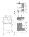
- a fifth step following the fourth step including depositing a contact stopper film, depositing an interlayer insulating film and performing chemical mechanical polishing to expose an upper portion of the second dummy gate and an upper portion of the first dummy gate, removing the second dummy gate and the first dummy gate, removing the second insulating film and the fourth insulating film, forming a gate insulating film around the pillar-shaped semiconductor layer and on inner sides of the fifth insulating film, depositing a metal, and performing etch-back to form a gate electrode and a gate line.
- a contact stopper film 118 is deposited and an interlayer insulating film 119 is deposited.
- the contact stopper film 118 is preferably a nitride film.
- chemical mechanical polishing is performed to expose an upper portion of the second dummy gate 113 and an upper portion of the first dummy gate 106 .
- the metal-semiconductor compound 117 formed in the upper portion of the second dummy gate 113 is removed.
- the second dummy gate 113 and the first dummy gate 106 are removed.
- the second insulating film 105 and the fourth insulating film 110 are removed.
- a gate insulating film 120 is formed around the pillar-shaped silicon layer 109 and on inner sides of the fifth insulating film (side wall) 114 , and a metal 121 is deposited.
- a gate electrode 121 a is formed around the pillar-shaped silicon layer 109 .
- a gate line 121 b is also formed. Since the gate insulating film 120 is formed around and at bottoms of the gate electrode 121 a and the gate line 121 b , the gate electrode 121 a and the gate line 121 b can be insulated from the pillar-shaped silicon layer 109 and the fin-shaped silicon layer 103 .
- the metal 121 is etched back to expose an upper portion of the pillar-shaped silicon layer 109 .
- an oxide film 122 is deposited.
- the oxide film 122 , the gate insulating film 120 , and the interlayer insulating film 119 are etched to form contact holes 124 and 125 .
- the oxide film 122 and the gate insulating film 120 are etched to form a contact hole 127 .
- a metal 128 is deposited to form contacts 129 , 130 , and 131 are formed.
- sixth resists 132 , 133 , and 134 for forming metal wiring are formed.
- the metal 128 is etched to form metal wiring 135 , 136 , and 137 .
- the sixth resists 132 , 133 , and 134 are removed.
- FIGS. 1A to 1C illustrate a structure of a semiconductor device obtained by the production method described above.
- a width of the pillar-shaped silicon layer 109 in a direction perpendicular to the fin-shaped silicon layer 103 is equal to a width of the fin-shaped silicon layer 103 in the direction perpendicular to the direction in which the fin-shaped semiconductor layer extends.
- the gate insulating film is also disposed around and at bottoms of gate electrode and the gate line.
- An outer width W 1 of the gate electrode 121 a is equal to a width W 2 of the gate line 121 b.
- the gate electrode 121 a and the gate line 121 b can be insulated from the pillar-shaped silicon layer 109 and the fin-shaped silicon layer 103 due to the presence of the gate insulating film 120 formed around and at bottoms of the gate electrode 121 a and the gate line 121 b.
- the technical scope of the present invention naturally includes a method for producing a semiconductor device in which the conductivity types, p (including p + ) and n (including n + ), are reversed from the embodiments described above, and a semiconductor device obtained through the method.
Landscapes
- Engineering & Computer Science (AREA)
- Power Engineering (AREA)
- Microelectronics & Electronic Packaging (AREA)
- Computer Hardware Design (AREA)
- Physics & Mathematics (AREA)
- Condensed Matter Physics & Semiconductors (AREA)
- General Physics & Mathematics (AREA)
- Ceramic Engineering (AREA)
- Manufacturing & Machinery (AREA)
- Chemical & Material Sciences (AREA)
- Crystallography & Structural Chemistry (AREA)
- Insulated Gate Type Field-Effect Transistor (AREA)
- Electrodes Of Semiconductors (AREA)
Priority Applications (2)
| Application Number | Priority Date | Filing Date | Title |
|---|---|---|---|
| US15/342,217 US10186601B2 (en) | 2013-06-10 | 2016-11-03 | Method for producing semiconductor device |
| US15/342,237 US10056471B2 (en) | 2013-06-10 | 2016-11-03 | Semiconductor device |
Applications Claiming Priority (1)
| Application Number | Priority Date | Filing Date | Title |
|---|---|---|---|
| PCT/JP2013/065998 WO2014199433A1 (ja) | 2013-06-10 | 2013-06-10 | 半導体装置の製造方法、及び、半導体装置 |
Related Parent Applications (1)
| Application Number | Title | Priority Date | Filing Date |
|---|---|---|---|
| PCT/JP2013/065998 Continuation WO2014199433A1 (ja) | 2013-06-10 | 2013-06-10 | 半導体装置の製造方法、及び、半導体装置 |
Related Child Applications (2)
| Application Number | Title | Priority Date | Filing Date |
|---|---|---|---|
| US15/342,237 Continuation US10056471B2 (en) | 2013-06-10 | 2016-11-03 | Semiconductor device |
| US15/342,217 Division US10186601B2 (en) | 2013-06-10 | 2016-11-03 | Method for producing semiconductor device |
Publications (2)
| Publication Number | Publication Date |
|---|---|
| US20150303296A1 US20150303296A1 (en) | 2015-10-22 |
| US9525038B2 true US9525038B2 (en) | 2016-12-20 |
Family
ID=52021769
Family Applications (3)
| Application Number | Title | Priority Date | Filing Date |
|---|---|---|---|
| US14/793,108 Active US9525038B2 (en) | 2013-06-10 | 2015-07-07 | Method for producing semiconductor device and semiconductor device |
| US15/342,217 Active 2033-10-26 US10186601B2 (en) | 2013-06-10 | 2016-11-03 | Method for producing semiconductor device |
| US15/342,237 Active 2033-10-12 US10056471B2 (en) | 2013-06-10 | 2016-11-03 | Semiconductor device |
Family Applications After (2)
| Application Number | Title | Priority Date | Filing Date |
|---|---|---|---|
| US15/342,217 Active 2033-10-26 US10186601B2 (en) | 2013-06-10 | 2016-11-03 | Method for producing semiconductor device |
| US15/342,237 Active 2033-10-12 US10056471B2 (en) | 2013-06-10 | 2016-11-03 | Semiconductor device |
Country Status (3)
| Country | Link |
|---|---|
| US (3) | US9525038B2 (ja) |
| JP (1) | JP5680801B1 (ja) |
| WO (1) | WO2014199433A1 (ja) |
Cited By (1)
| Publication number | Priority date | Publication date | Assignee | Title |
|---|---|---|---|---|
| US9653465B1 (en) * | 2016-09-12 | 2017-05-16 | International Business Machines Corporation | Vertical transistors having different gate lengths |
Families Citing this family (2)
| Publication number | Priority date | Publication date | Assignee | Title |
|---|---|---|---|---|
| JP5822326B1 (ja) * | 2014-02-18 | 2015-11-24 | ユニサンティス エレクトロニクス シンガポール プライベート リミテッドUnisantis Electronics Singapore Pte Ltd. | 半導体装置の製造方法、及び、半導体装置 |
| US9318447B2 (en) * | 2014-07-18 | 2016-04-19 | Taiwan Semiconductor Manufacturing Company Limited | Semiconductor device and method of forming vertical structure |
Citations (11)
| Publication number | Priority date | Publication date | Assignee | Title |
|---|---|---|---|---|
| JPH0271556A (ja) | 1988-09-06 | 1990-03-12 | Toshiba Corp | 半導体装置 |
| JPH02188966A (ja) | 1989-01-17 | 1990-07-25 | Toshiba Corp | Mos型半導体装置 |
| JPH03145761A (ja) | 1989-11-01 | 1991-06-20 | Toshiba Corp | 半導体装置 |
| US20070284623A1 (en) * | 2006-05-24 | 2007-12-13 | Sang-Jin Kim | Semiconductor device having vertical channel transistor |
| US20080173937A1 (en) * | 2007-01-18 | 2008-07-24 | Samsung Electronics Co., Ltd. | Semiconductor memory devices including vertically oriented transistors and methods of manufacturing such devices |
| JP2009182317A (ja) | 2008-01-29 | 2009-08-13 | Unisantis Electronics Japan Ltd | 半導体装置の製造方法 |
| WO2009110050A1 (ja) | 2008-02-15 | 2009-09-11 | 日本ユニサンティスエレクトロニクス株式会社 | 半導体装置の製造方法 |
| JP2010251586A (ja) | 2009-04-17 | 2010-11-04 | Unisantis Electronics Japan Ltd | 半導体装置 |
| US20120142154A1 (en) | 2008-02-15 | 2012-06-07 | Unisantis Electronics Singapore Pte Ltd. | Production method for semiconductor device |
| WO2013069102A1 (ja) | 2011-11-09 | 2013-05-16 | ユニサンティス エレクトロニクス シンガポール プライベート リミテッド | 半導体装置の製造方法及び半導体装置 |
| WO2013080378A1 (ja) | 2011-12-02 | 2013-06-06 | ユニサンティス エレクトロニクス シンガポール プライベート リミテッド | 半導体装置の製造方法と半導体装置 |
-
2013
- 2013-06-10 WO PCT/JP2013/065998 patent/WO2014199433A1/ja active Application Filing
- 2013-06-10 JP JP2014521767A patent/JP5680801B1/ja active Active
-
2015
- 2015-07-07 US US14/793,108 patent/US9525038B2/en active Active
-
2016
- 2016-11-03 US US15/342,217 patent/US10186601B2/en active Active
- 2016-11-03 US US15/342,237 patent/US10056471B2/en active Active
Patent Citations (11)
| Publication number | Priority date | Publication date | Assignee | Title |
|---|---|---|---|---|
| JPH0271556A (ja) | 1988-09-06 | 1990-03-12 | Toshiba Corp | 半導体装置 |
| JPH02188966A (ja) | 1989-01-17 | 1990-07-25 | Toshiba Corp | Mos型半導体装置 |
| JPH03145761A (ja) | 1989-11-01 | 1991-06-20 | Toshiba Corp | 半導体装置 |
| US20070284623A1 (en) * | 2006-05-24 | 2007-12-13 | Sang-Jin Kim | Semiconductor device having vertical channel transistor |
| US20080173937A1 (en) * | 2007-01-18 | 2008-07-24 | Samsung Electronics Co., Ltd. | Semiconductor memory devices including vertically oriented transistors and methods of manufacturing such devices |
| JP2009182317A (ja) | 2008-01-29 | 2009-08-13 | Unisantis Electronics Japan Ltd | 半導体装置の製造方法 |
| WO2009110050A1 (ja) | 2008-02-15 | 2009-09-11 | 日本ユニサンティスエレクトロニクス株式会社 | 半導体装置の製造方法 |
| US20120142154A1 (en) | 2008-02-15 | 2012-06-07 | Unisantis Electronics Singapore Pte Ltd. | Production method for semiconductor device |
| JP2010251586A (ja) | 2009-04-17 | 2010-11-04 | Unisantis Electronics Japan Ltd | 半導体装置 |
| WO2013069102A1 (ja) | 2011-11-09 | 2013-05-16 | ユニサンティス エレクトロニクス シンガポール プライベート リミテッド | 半導体装置の製造方法及び半導体装置 |
| WO2013080378A1 (ja) | 2011-12-02 | 2013-06-06 | ユニサンティス エレクトロニクス シンガポール プライベート リミテッド | 半導体装置の製造方法と半導体装置 |
Non-Patent Citations (4)
| Title |
|---|
| International Preliminary Report on Patentability and English language translation thereof, in corresponding International Application No. PCT/JP2013/065998 dated Dec. 23, 2015, 11 pages. |
| International Search Report and Written Opinion with English Translation for PCT/JP2013/065998 dated Aug. 20, 2013, 5 pages. |
| Mistry et al., "A 45nm Logic Technology with High-k+Metal Gate Transistors, Strained Silicon, 9 Cu Interconnect Layers, 193nm Dry Patterning, and 100% Pb-free Packaging", IEEE, pp. 247-250, 2007. |
| Wu et al., "High Performance 22/20nm FinFET CMOS Devices with Advanced High-K/Metal Gate Scheme", IEEE, pp. 27.1.1-27.1.4, 2010. |
Cited By (1)
| Publication number | Priority date | Publication date | Assignee | Title |
|---|---|---|---|---|
| US9653465B1 (en) * | 2016-09-12 | 2017-05-16 | International Business Machines Corporation | Vertical transistors having different gate lengths |
Also Published As
| Publication number | Publication date |
|---|---|
| US20170077267A1 (en) | 2017-03-16 |
| US10056471B2 (en) | 2018-08-21 |
| US20170077265A1 (en) | 2017-03-16 |
| WO2014199433A1 (ja) | 2014-12-18 |
| JPWO2014199433A1 (ja) | 2017-02-23 |
| US20150303296A1 (en) | 2015-10-22 |
| JP5680801B1 (ja) | 2015-03-04 |
| US10186601B2 (en) | 2019-01-22 |
Similar Documents
| Publication | Publication Date | Title |
|---|---|---|
| US10008595B2 (en) | Method for producing semiconductor device and semiconductor device | |
| US9876087B2 (en) | Surround gate transistor device and contact structure for same | |
| US9812547B2 (en) | Semiconductor device having fin-shaped semiconductor layer | |
| US9960277B2 (en) | Method for producing semiconductor device | |
| US10804397B2 (en) | Semiconductor device with surrounding gate transistor (SGT) | |
| US10056471B2 (en) | Semiconductor device | |
| US10937902B2 (en) | Method for producing a semiconductor device having a fin-shaped semiconductor layer | |
| US9842926B2 (en) | Method for producing semiconductor device and semiconductor device | |
| US9647142B2 (en) | Method for producing semiconductor device and semiconductor device | |
| JP5861197B2 (ja) | 半導体装置の製造方法、及び、半導体装置 | |
| JP6121386B2 (ja) | 半導体装置の製造方法、及び、半導体装置 | |
| JP2015159337A (ja) | 半導体装置の製造方法、及び、半導体装置 |
Legal Events
| Date | Code | Title | Description |
|---|---|---|---|
| AS | Assignment |
Owner name: UNISANTIS ELECTRONICS SINGAPORE PTE. LTD., SINGAPO Free format text: ASSIGNMENT OF ASSIGNORS INTEREST;ASSIGNORS:MASUOKA, FUJIO;NAKAMURA, HIROKI;SIGNING DATES FROM 20150616 TO 20150617;REEL/FRAME:036013/0303 |
|
| STCF | Information on status: patent grant |
Free format text: PATENTED CASE |
|
| MAFP | Maintenance fee payment |
Free format text: PAYMENT OF MAINTENANCE FEE, 4TH YR, SMALL ENTITY (ORIGINAL EVENT CODE: M2551); ENTITY STATUS OF PATENT OWNER: SMALL ENTITY Year of fee payment: 4 |
|
| MAFP | Maintenance fee payment |
Free format text: PAYMENT OF MAINTENANCE FEE, 8TH YR, SMALL ENTITY (ORIGINAL EVENT CODE: M2552); ENTITY STATUS OF PATENT OWNER: SMALL ENTITY Year of fee payment: 8 |