US9520759B2 - Motor driven compressor - Google Patents
Motor driven compressor Download PDFInfo
- Publication number
- US9520759B2 US9520759B2 US14/070,037 US201314070037A US9520759B2 US 9520759 B2 US9520759 B2 US 9520759B2 US 201314070037 A US201314070037 A US 201314070037A US 9520759 B2 US9520759 B2 US 9520759B2
- Authority
- US
- United States
- Prior art keywords
- bolt
- insertion hole
- cover
- housing
- motor
- Prior art date
- Legal status (The legal status is an assumption and is not a legal conclusion. Google has not performed a legal analysis and makes no representation as to the accuracy of the status listed.)
- Expired - Fee Related, expires
Links
- 239000011347 resin Substances 0.000 claims abstract description 57
- 229920005989 resin Polymers 0.000 claims abstract description 57
- 230000037431 insertion Effects 0.000 claims abstract description 52
- 238000003780 insertion Methods 0.000 claims abstract description 52
- 229910052751 metal Inorganic materials 0.000 claims abstract description 17
- 239000002184 metal Substances 0.000 claims abstract description 17
- 230000006835 compression Effects 0.000 claims abstract description 14
- 238000007906 compression Methods 0.000 claims abstract description 14
- 238000007789 sealing Methods 0.000 claims description 25
- 125000006850 spacer group Chemical group 0.000 claims description 8
- 229910052782 aluminium Inorganic materials 0.000 description 6
- XAGFODPZIPBFFR-UHFFFAOYSA-N aluminium Chemical compound [Al] XAGFODPZIPBFFR-UHFFFAOYSA-N 0.000 description 6
- XEEYBQQBJWHFJM-UHFFFAOYSA-N Iron Chemical compound [Fe] XEEYBQQBJWHFJM-UHFFFAOYSA-N 0.000 description 4
- 230000015556 catabolic process Effects 0.000 description 4
- 238000006731 degradation reaction Methods 0.000 description 4
- 239000003507 refrigerant Substances 0.000 description 4
- 239000004020 conductor Substances 0.000 description 2
- 229910052742 iron Inorganic materials 0.000 description 2
- RYGMFSIKBFXOCR-UHFFFAOYSA-N Copper Chemical compound [Cu] RYGMFSIKBFXOCR-UHFFFAOYSA-N 0.000 description 1
- 239000000853 adhesive Substances 0.000 description 1
- 230000001070 adhesive effect Effects 0.000 description 1
- 230000002411 adverse Effects 0.000 description 1
- 229910052802 copper Inorganic materials 0.000 description 1
- 239000010949 copper Substances 0.000 description 1
- 230000007797 corrosion Effects 0.000 description 1
- 238000005260 corrosion Methods 0.000 description 1
- 239000011810 insulating material Substances 0.000 description 1
- 230000002093 peripheral effect Effects 0.000 description 1
- XLYOFNOQVPJJNP-UHFFFAOYSA-N water Substances O XLYOFNOQVPJJNP-UHFFFAOYSA-N 0.000 description 1
Images



Classifications
-
- H—ELECTRICITY
- H02—GENERATION; CONVERSION OR DISTRIBUTION OF ELECTRIC POWER
- H02K—DYNAMO-ELECTRIC MACHINES
- H02K11/00—Structural association of dynamo-electric machines with electric components or with devices for shielding, monitoring or protection
- H02K11/01—Structural association of dynamo-electric machines with electric components or with devices for shielding, monitoring or protection for shielding from electromagnetic fields, i.e. structural association with shields
- H02K11/014—Shields associated with stationary parts, e.g. stator cores
- H02K11/0141—Shields associated with casings, enclosures or brackets
-
- F—MECHANICAL ENGINEERING; LIGHTING; HEATING; WEAPONS; BLASTING
- F04—POSITIVE - DISPLACEMENT MACHINES FOR LIQUIDS; PUMPS FOR LIQUIDS OR ELASTIC FLUIDS
- F04B—POSITIVE-DISPLACEMENT MACHINES FOR LIQUIDS; PUMPS
- F04B39/00—Component parts, details, or accessories, of pumps or pumping systems specially adapted for elastic fluids, not otherwise provided for in, or of interest apart from, groups F04B25/00 - F04B37/00
-
- H02K11/022—
-
- F—MECHANICAL ENGINEERING; LIGHTING; HEATING; WEAPONS; BLASTING
- F04—POSITIVE - DISPLACEMENT MACHINES FOR LIQUIDS; PUMPS FOR LIQUIDS OR ELASTIC FLUIDS
- F04B—POSITIVE-DISPLACEMENT MACHINES FOR LIQUIDS; PUMPS
- F04B35/00—Piston pumps specially adapted for elastic fluids and characterised by the driving means to their working members, or by combination with, or adaptation to, specific driving engines or motors, not otherwise provided for
- F04B35/04—Piston pumps specially adapted for elastic fluids and characterised by the driving means to their working members, or by combination with, or adaptation to, specific driving engines or motors, not otherwise provided for the means being electric
-
- F—MECHANICAL ENGINEERING; LIGHTING; HEATING; WEAPONS; BLASTING
- F04—POSITIVE - DISPLACEMENT MACHINES FOR LIQUIDS; PUMPS FOR LIQUIDS OR ELASTIC FLUIDS
- F04B—POSITIVE-DISPLACEMENT MACHINES FOR LIQUIDS; PUMPS
- F04B39/00—Component parts, details, or accessories, of pumps or pumping systems specially adapted for elastic fluids, not otherwise provided for in, or of interest apart from, groups F04B25/00 - F04B37/00
- F04B39/12—Casings; Cylinders; Cylinder heads; Fluid connections
-
- F—MECHANICAL ENGINEERING; LIGHTING; HEATING; WEAPONS; BLASTING
- F04—POSITIVE - DISPLACEMENT MACHINES FOR LIQUIDS; PUMPS FOR LIQUIDS OR ELASTIC FLUIDS
- F04B—POSITIVE-DISPLACEMENT MACHINES FOR LIQUIDS; PUMPS
- F04B39/00—Component parts, details, or accessories, of pumps or pumping systems specially adapted for elastic fluids, not otherwise provided for in, or of interest apart from, groups F04B25/00 - F04B37/00
- F04B39/12—Casings; Cylinders; Cylinder heads; Fluid connections
- F04B39/121—Casings
-
- F—MECHANICAL ENGINEERING; LIGHTING; HEATING; WEAPONS; BLASTING
- F04—POSITIVE - DISPLACEMENT MACHINES FOR LIQUIDS; PUMPS FOR LIQUIDS OR ELASTIC FLUIDS
- F04C—ROTARY-PISTON, OR OSCILLATING-PISTON, POSITIVE-DISPLACEMENT MACHINES FOR LIQUIDS; ROTARY-PISTON, OR OSCILLATING-PISTON, POSITIVE-DISPLACEMENT PUMPS
- F04C29/00—Component parts, details or accessories of pumps or pumping installations, not provided for in groups F04C18/00 - F04C28/00
-
- H—ELECTRICITY
- H02—GENERATION; CONVERSION OR DISTRIBUTION OF ELECTRIC POWER
- H02K—DYNAMO-ELECTRIC MACHINES
- H02K11/00—Structural association of dynamo-electric machines with electric components or with devices for shielding, monitoring or protection
- H02K11/02—Structural association of dynamo-electric machines with electric components or with devices for shielding, monitoring or protection for suppression of electromagnetic interference
-
- H—ELECTRICITY
- H02—GENERATION; CONVERSION OR DISTRIBUTION OF ELECTRIC POWER
- H02K—DYNAMO-ELECTRIC MACHINES
- H02K5/00—Casings; Enclosures; Supports
- H02K5/04—Casings or enclosures characterised by the shape, form or construction thereof
- H02K5/08—Insulating casings
-
- H—ELECTRICITY
- H02—GENERATION; CONVERSION OR DISTRIBUTION OF ELECTRIC POWER
- H02K—DYNAMO-ELECTRIC MACHINES
- H02K5/00—Casings; Enclosures; Supports
- H02K5/24—Casings; Enclosures; Supports specially adapted for suppression or reduction of noise or vibrations
Definitions
- the present invention relates to a motor-driven compressor.
- a motor-driven compressor includes a metal housing accommodating a compression unit, which compresses and discharges refrigerant, and an electric motor, which drives the compression unit.
- a cover that defines an accommodating chamber is coupled to the housing. The accommodating chamber accommodates a motor driving circuit that drives the electric motor.
- the cover When the cover is made of metal, the overall weight of the motor-driven compressor increases.
- the use of a resin cover allows for the motor-driven compressor to be lighter.
- a resin cover would transmit electromagnetic noise from outside the compressor to the motor driving circuit.
- electromagnetic noise from the motor driving circuit may leak out of the compressor through the resin cover.
- Japanese Laid-Open Patent Publication No. 2008-215236 discloses a laminated cover including a conductive layer (shield), which is made of a conductive material such as aluminum and iron, and an insulating layer (resin portion), which is made of an insulating material such as resin and rubber.
- the cover is coupled to a housing by a bolt, with the conductive layer in contact with the housing.
- Electromagnetic noise from the exterior is blocked by the conductive layer and transmitted to the housing. This suppresses electromagnetic noise entering the accommodating chamber through the insulating layer.
- electromagnetic noise from the motor driving circuit is blocked by the conductive layer and transmitted to the housing. This suppresses the leakage of electromagnetic noise from the motor driving circuit to the exterior through the insulating layer.
- the cover of the publication when the cover of the publication is coupled to the housing, the conductive layer and the insulating layer are held between the housing and the bolt.
- the axial force of the bolt tends to deform the insulating layer.
- Deformation of the insulating layer may loosen the bolt and adversely affect the seal between the housing and the cover. This may result in foreign matter or water entering the accommodating chamber through a gap between the housing and the cover.
- one aspect of the present invention is a motor-driven compressor that includes a metal housing accommodating a compression unit and an electric motor, a cover coupled to the housing, wherein the cover includes a resin portion and a metal shield, and the shield blocks electromagnetic noise, and a bolt that couples the cover to the housing.
- the housing and the cover define an accommodating chamber that accommodates a motor driving circuit that drives the electric motor.
- the cover includes an insertion hole into which the bolt is insertable.
- the shield includes a seat that surrounds the insertion hole and is held between the bolt and the housing. The cover is configured to allow for an axial force of the bolt to be applied to the seat and not to the resin portion.
- FIG. 1A is a partial cross-sectional view showing a motor-driven compressor of a first embodiment
- FIG. 1B is an enlarged cross-sectional view showing a bolt in the motor-driven compressor of FIG. 1 ;
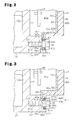
- FIG. 2 is an enlarged cross-sectional view showing a bolt of a second embodiment
- FIG. 3 is an enlarged cross-sectional view showing a bolt of another embodiment
- FIG. 4 is an enlarged cross-sectional view showing a bolt of a further embodiment.
- FIG. 5 is an enlarged cross-sectional view showing a bolt of a yet another embodiment.
- FIGS. 1A and 1B a motor-driven compressor of the first embodiment will now be described.
- a motor-driven compressor 10 includes a housing H that includes an aluminum (metal) discharge housing member 11 and an aluminum (metal) suction housing member 12 coupled to the discharge housing member 11 .
- the discharge housing member 11 and the suction housing member 12 are cylindrical, and each includes an open end and a closed end.
- the suction housing member 12 has a peripheral wall including a suction port (not shown).
- the suction port is connected to an external refrigerant circuit (not shown).
- the discharge housing member 11 includes a discharge port 14 connected to the external refrigerant circuit.
- the suction housing member 12 accommodates a compression unit 15 (indicated by the broken lines in FIG. 1 ), which compresses refrigerant, and an electric motor 16 , which drives the compression unit 15 .
- the compression unit 15 of the present embodiment includes a fixed scroll, which is fixed in the suction housing member 12 , and a movable scroll, which is engaged with the fixed scroll.
- a stator 17 is fixed to the inner surface of the suction housing member 12 .
- the stator 17 includes a stator core 17 a , which is fixed to the inner surface of the suction housing member 12 , and coils 17 b , which are wound around teeth (not shown) of the stator core 17 a .
- a rotatable rotation shaft 19 extends through the stator 17 in the suction housing member 12 .
- a rotor 18 is fixed to the rotation shaft 19 .
- the suction housing member 12 includes an end wall 12 a that includes an annular flange 12 f .
- the flange 12 f extends from the entire rim of the end wall 12 a in the direction of an axis L of the rotation shaft 19 .
- the flange 12 f has an open end to which a cover 41 is coupled.
- the cover 41 is cylindrical and has a closed end.
- the end wall 12 a , the flange 12 f , and the cover 41 define an accommodating chamber 41 a .
- the accommodating chamber 41 a accommodates a motor driving circuit 40 that drives the electric motor 16 .
- the motor driving circuit 40 is connected to the electric motor 16 by wires (not shown).
- the motor driving circuit 40 is coupled to the end wall 12 a in the accommodating chamber 41 a .
- the compression unit 15 , the electric motor 16 , and the motor driving circuit 40 are arranged in this order in the axial direction of the rotation shaft 19 .
- the cover 41 includes a resin portion 42 , which is cylindrical and has a closed end, and an aluminum (metal) shield 43 , which is formed from a thin plate.
- the cover 41 is molded from resin using the shield 43 as the core.
- the shield 43 is located inside the resin portion 42 .
- the resin portion 42 includes an outer tubular portion 42 a and an outer lid 42 b .
- the outer tubular portion 42 a is annular and extends in the axial direction of the rotation shaft 19 .
- the outer lid 42 b is continuous with the outer tubular portion 42 a and extends perpendicular to the outer tubular portion 42 a.
- the shield 43 includes a tubular portion 43 a and a lid 43 b .
- the tubular portion 43 a is annular and extends in the axial direction of the rotation shaft 19 .
- the lid 43 b is continuous with the tubular portion 43 a and extends perpendicular to the tubular portion 43 a .
- the tubular portion 43 a extends along the inner circumferential surface of the outer tubular portion 42 a of the resin portion 42 .
- the lid 43 b extends along the inner end surface of the lid 42 b of the resin portion 42 .
- the resin portion 42 includes an outer coupler 42 f that projects radially outward from the outer tubular portion 42 a .
- the shield 43 has a coupler 43 f extending along the inner end surface of the outer coupler 42 f .
- the outer coupler 42 f is located outside the coupler 43 f and covers the outer side of the coupler 43 f .
- the inner surface of the coupler 43 f that faces toward the suction housing member 12 is in contact with the flange 12 f of the suction housing member 12 .
- the shield 43 extends over the entire inner surface of the resin portion 42 and blocks electromagnetic noise transmitted from the resin portion 42 .
- the cover 41 includes an insertion hole 41 h into which a bolt 50 is insertable.
- the bolt 50 couples the cover 41 to the suction housing member 12 .
- the insertion hole 41 h includes a first insertion hole 43 h , which is formed in the coupler 43 f , and a second insertion hole 42 h , which is formed in the outer coupler 42 f .
- the second insertion hole 42 h has a larger diameter than the first insertion hole 43 h .
- the first insertion hole 43 h is aligned with the second insertion hole 42 h .
- the bolt 50 includes a threaded shaft 50 a and a head 50 b , which is located at one end of the shaft 50 a .
- a tube 51 is arranged in the second insertion hole 42 h .
- the bolt 50 is inserted into the tube 51 .
- the tube 51 functions as a spacer held between the bolt 50 and the coupler 43 f .
- the tube 51 is made of aluminum (metal).
- the tube 51 is integrally fixed to the outer coupler 42 f by an adhesive applied between the outer circumferential surface of the tube 51 and the outer coupler 42 f . This seals the gap between the tube 51 and the outer coupler 42 f .
- the end surface of the tube 51 facing toward the head 50 b is located outward from the outer surface of the outer coupler 42 f.
- An annular first sealing member 52 is arranged between the tube 51 and the head 50 b of the bolt 50 in the axial direction of the shaft 50 a of the bolt 50 .
- the first sealing member 52 which is made of aluminum (metal), surrounds the shaft 50 a and seals the gap between the tube 51 and the head 50 b.
- the end surface of the tube 51 that faces toward the suction housing member 12 is in contact with a portion of the coupler 43 f surrounding the first insertion hole 43 h .
- the wall of the first insertion hole 43 h is located at the inner side of the wall of the second insertion hole 42 h .
- the portion of the coupler 43 f surrounding the first insertion hole 43 h functions as a seat 43 e held between the head 50 b of the bolt 50 and the flange 12 f of the suction housing member 12 .
- the axial force of the bolt 50 is applied to the seat 43 e through the tube 51 and not applied to the resin portion 42 .
- the flange 12 f includes a threaded hole 12 h with which the shaft 50 a of the bolt 50 may be fastened.
- the axial force of the bolt 50 is applied to the seat 43 e through the tube 51 and not applied to the resin portion 42 .
- the seat 43 e and the tube 51 are held between the head 50 b of the bolt 50 and the flange 12 f of the suction housing member 12 . Consequently, when the cover 41 is coupled to the suction housing member 12 by the bolt 50 , the resin portion 42 is not held between the bolt 50 and the suction housing member 12 .
- the axial force of the bolt 50 does not deform the resin portion 42 . This avoids degradation of the seal between the suction housing member 12 and the cover 41 that would be caused when the resin portion 42 deforms and loosens the bolt 50 .
- the portion of the coupler 43 f surrounding the first insertion hole 43 h functions as the seat 43 e held between the head 50 b of the bolt 50 and the flange 12 f of the suction housing member 12 .
- the axial force of the bolt 50 is applied to the seat 43 e through the tube 51 and not applied to the resin portion 42 . Consequently, when the cover 41 is coupled to the suction housing member 12 by the bolt 50 , the resin portion 42 is not held between the bolt 50 and the suction housing member 12 .
- the axial force of the bolt 50 does not deform the resin portion 42 . This avoids degradation of the seal between the suction housing member 12 and the cover 41 that would be caused when the resin portion 42 deforms and loosens the bolt 50 .
- the second insertion hole 42 h receives the tube 51 into which the bolt 50 is inserted.
- the tube 51 receives the axial force of the bolt 50 and is held between the bolt 50 and the seat 43 e .
- the inner end surface of the tube 51 that faces toward the suction housing member 12 is in contact with the seat 43 e .
- the axial force of the bolt 50 is applied to the seat 43 e through the tube 51 , and the outer coupler 42 f does not receive the axial force of the bolt 50 .
- the tube 51 is integrally fixed to the outer coupler 42 f of the resin portion 42 . This ensures the seal between the tube 51 and the outer coupler 42 f.
- the first sealing member 52 is arranged between the tube 51 and the head 50 b of the bolt 50 in the axial direction of the shaft 50 a of the bolt 50 . This ensures the seal between the tube 51 and the head 50 b.
- the shield 43 extends over the entire inner surface of the resin portion 42 . That is, the shield 43 is not located outside of the resin portion 42 . This protects the shield 43 from corrosion.
- the outer end surface of the tube 51 that faces toward the head 50 b is located outward from the outer surface of the outer coupler 42 f of the resin portion 42 .
- the tube 51 restricts contact between the head 50 b of the bolt 50 and the outer surface of the outer coupler 42 f . This avoids deformation of the resin portion 42 that would be caused by the axial force of the bolt 50 .
- a bolt 60 includes a threaded shaft 60 a , which is arranged in the first insertion hole 43 h , a large diameter portion 60 c , which is arranged in the second insertion hole 42 h and has a larger diameter than the shaft 60 a , and a head 60 b .
- the head 60 b and the shaft 60 a are located at opposite sides of the large diameter portion 60 c .
- a first step 60 d is formed between the shaft 60 a and the large diameter portion 60 c
- a second step 60 e is formed between the large diameter portion 60 c and the head 60 b .
- the first step 60 d is in contact with the seat 43 e .
- the second step 60 e is located in the second insertion hole 42 h.
- An annular second sealing member 62 is arranged in the second insertion hole 42 h .
- the second sealing member 62 is arranged between the large diameter portion 60 c and the outer coupler 42 f and surrounds the large diameter portion 60 c .
- the second sealing member 62 which is made of rubber, is in contact with the second step 60 e and seals the gap between the large diameter portion 60 c and the outer coupler 42 f .
- the bolt 60 fastens the cover 41 to the suction housing member 12
- the second sealing member 62 is pressed by the second step 60 e toward the suction housing member 12 and elastically deformed.
- the second sealing member 62 is held between the second step 60 e and the coupler 43 f in the axial direction of the shaft 60 a of the bolt 60 . This further improves the seal between the large diameter portion 60 c and the outer coupler 42 f.
- the axial force of the bolt 60 is applied to the seat 43 e through the first step 60 d and not applied to the resin portion 42 .
- the seat 43 e and the large diameter portion 60 c are held between the head 60 b of the bolt 60 and the flange 12 f of the suction housing member 12 .
- the cover 41 is coupled to the suction housing member 12 by the bolt 60
- the resin portion 42 is not held between the bolt 60 and the suction housing member 12 .
- the axial force of the bolt 50 does not deform the resin portion 42 . This avoids degradation of the seal between the suction housing member 12 and the cover 41 that would be caused when the resin portion 42 deforms and loosens the bolt 60 .
- the second embodiment has the following advantages in addition to advantages (1) and (5) of the first embodiment.
- the bolt 60 includes the shaft 60 a , which is arranged in the first insertion hole 43 h , the large diameter portion 60 c , which is arranged in the second insertion hole 42 h and has a larger diameter than the shaft 60 a , and the head 60 b .
- the head 60 b and the shaft 60 a are located at opposite sides of the large diameter portion 60 c .
- the first step 60 d is formed between the shaft 60 a and the large diameter portion 60 c
- the second step 60 e is formed between the large diameter portion 60 c and the head 60 b .
- the first step 60 d is in contact with the seat 43 e .
- the axial force of the bolt 60 is applied to the seat 43 e by the first step 60 d .
- the second embodiment uses fewer components.
- the second sealing member 62 is arranged between the large diameter portion 60 c and the outer coupler 42 f and surrounds the large diameter portion 60 c . This ensures the seal between the large diameter portion 60 c and the outer coupler 42 f.
- the second sealing member 62 is pressed by the second step 60 e toward the suction housing member 12 and elastically deformed. This further improves the seal between the large diameter portion 60 c and the outer coupler 42 f.
- the second sealing member 62 is held between the second step 60 e and the coupler 43 f in the axial direction of the bolt 60 . If the second sealing member 62 were held between the second step 60 e and the resin portion 42 , for example, the resin portion 42 would receive the axial force of the bolt 60 through the second sealing member 62 and be deformed.
- the second insertion hole 42 h may include a large portion 421 h and a small portion 422 h .
- the small portion 422 h has a smaller diameter than the large portion 421 h and is closer to the shield 43 than the large portion 421 h .
- a step 423 h is formed between the large portion 421 h and the small portion 422 h .
- the second sealing member 62 may be arranged in the large portion 421 h between the large diameter portion 60 c and the outer coupler 42 f .
- the second sealing member 62 may be held between the second step 60 e and the step 423 h in the axial direction of the shaft 60 a of the bolt 60 . This facilitates deformation of the second sealing member 62 in the second insertion hole 42 h and further improves the seal between the large diameter portion 60 c and the outer coupler 42 f.
- annular sealing member 51 s may be arranged on the outer circumferential surface of the tube 51 .
- the sealing member 51 s seals the gap between the outer circumferential surface of the tube 51 and the outer coupler 42 f.
- the resin portion 42 does not have to include the outer coupler 42 f .
- the cover 41 may be coupled to the suction housing member 12 by inserting the bolt 50 into the first insertion hole 43 h and engaging the shaft 50 a with the threaded hole 12 h .
- the axial force of the bolt 50 is applied to the seat 43 e and not applied to the resin portion 42 , and the seat 43 e is held between the head 50 b of the bolt 50 and the flange 12 f of the suction housing member 12 .
- the cover 41 is coupled to the suction housing member 12 by the bolt 50 , the resin portion 42 is not held between the bolt 50 and the suction housing member 12 .
- the axial force of the bolt 50 does not deform the resin portion 42 .
- the cover 41 may include a further resin portion at the inner side of the shield 43 .
- the outer end surface of the tube 51 may be flush with the outer surface of the outer coupler 42 f . Further, the outer end surface of the tube 51 facing toward the head 50 b may be closer to the suction housing member 12 than the outer surface of the outer coupler 42 f . In this case, the head 50 b of the bolt 50 is required to not be in contact with the outer surface of the outer coupler 42 f and be located in the second insertion hole 42 h , for example.
- the shield 43 may be made of a conductive material such as iron or copper.
- the compression unit 15 , the electric motor 16 , and the motor driving circuit 40 do not have to be arranged in this order in the axial direction of the rotation shaft 19 .
- the cover 41 may be fixed to the circumferential wall of the suction housing member 12 , and the motor driving circuit 40 may be accommodated in an accommodating chamber defined by the circumferential wall of the suction housing member 12 and the cover 41 .
- the compression unit 15 may be of a piston type or a vane type.
- the electric motor includes a rotor
- the housing accommodates a rotation shaft that rotates integrally with the rotor
- the compression unit, the electric motor, and the motor driving circuit are arranged in this order in an axial direction of the rotation shaft.
Landscapes
- Engineering & Computer Science (AREA)
- Mechanical Engineering (AREA)
- General Engineering & Computer Science (AREA)
- Power Engineering (AREA)
- Physics & Mathematics (AREA)
- Electromagnetism (AREA)
- Compressor (AREA)
- Structures Of Non-Positive Displacement Pumps (AREA)
Applications Claiming Priority (2)
| Application Number | Priority Date | Filing Date | Title |
|---|---|---|---|
| JP2012251141A JP6098128B2 (ja) | 2012-11-15 | 2012-11-15 | 電動圧縮機 |
| JP2012-251141 | 2012-11-15 |
Publications (2)
| Publication Number | Publication Date |
|---|---|
| US20140134017A1 US20140134017A1 (en) | 2014-05-15 |
| US9520759B2 true US9520759B2 (en) | 2016-12-13 |
Family
ID=49518804
Family Applications (1)
| Application Number | Title | Priority Date | Filing Date |
|---|---|---|---|
| US14/070,037 Expired - Fee Related US9520759B2 (en) | 2012-11-15 | 2013-11-01 | Motor driven compressor |
Country Status (5)
| Country | Link |
|---|---|
| US (1) | US9520759B2 (de) |
| EP (1) | EP2733352B1 (de) |
| JP (1) | JP6098128B2 (de) |
| KR (1) | KR101482885B1 (de) |
| CN (1) | CN103821691B (de) |
Families Citing this family (7)
| Publication number | Priority date | Publication date | Assignee | Title |
|---|---|---|---|---|
| JP6098128B2 (ja) * | 2012-11-15 | 2017-03-22 | 株式会社豊田自動織機 | 電動圧縮機 |
| JP5751291B2 (ja) | 2013-07-30 | 2015-07-22 | 株式会社豊田自動織機 | 電動圧縮機 |
| JP2019152199A (ja) * | 2018-03-06 | 2019-09-12 | アイシン精機株式会社 | 電動ポンプ |
| JP7040406B2 (ja) * | 2018-10-31 | 2022-03-23 | 株式会社豊田自動織機 | 電動圧縮機 |
| JP7314814B2 (ja) * | 2020-01-29 | 2023-07-26 | 株式会社豊田自動織機 | 電動圧縮機 |
| US11387593B2 (en) * | 2020-08-05 | 2022-07-12 | Lg Electronics Inc. | High voltage connector assembly and motor-operated compressor including the same |
| GB2643445A (en) * | 2024-08-15 | 2026-02-18 | Jaguar Land Rover Ltd | Electric machine cover |
Citations (22)
| Publication number | Priority date | Publication date | Assignee | Title |
|---|---|---|---|---|
| US4499391A (en) * | 1981-12-28 | 1985-02-12 | Japan Servo Co., Ltd. | End bracket for motor |
| JPH0240106U (de) | 1988-09-12 | 1990-03-19 | ||
| JPH0253506U (de) | 1988-10-11 | 1990-04-18 | ||
| US4941769A (en) * | 1988-04-05 | 1990-07-17 | Yazaki Corporation | Structure for fastening a resin member with a threaded bolt |
| JPH09137813A (ja) | 1995-11-15 | 1997-05-27 | Aoyama Seisakusho:Kk | バンパー取付用鍔付ボルト |
| US6321536B1 (en) * | 2000-12-07 | 2001-11-27 | Cummins Engine Company, Inc. | Pneumatically controlled exhaust throttle for delivering EGR on turbocharged engines |
| JP2003133756A (ja) | 2001-10-25 | 2003-05-09 | Nissan Motor Co Ltd | 電子ユニットの筐体構造 |
| US6617719B2 (en) * | 2000-03-02 | 2003-09-09 | Calsonic Kansei Corporation | Brushless motor |
| US6619933B2 (en) * | 2000-08-29 | 2003-09-16 | Sanden Corporation | Motor-driven compressors |
| US20040108778A1 (en) * | 2002-12-05 | 2004-06-10 | Nissan Motor Co., Ltd. | Integrated drive motor unit for a vehicle |
| EP1450044A2 (de) | 2003-02-19 | 2004-08-25 | Kabushiki Kaisha Toyota Jidoshokki | Elektrischer Kompressor und dessen Zusammenbauverfahren |
| JP2005110328A (ja) | 2003-08-05 | 2005-04-21 | Shinwa Kogyo Kk | インバータカバー |
| US7122928B2 (en) * | 2003-01-20 | 2006-10-17 | Denso Corporation | Housing for electronic circuit |
| JP2008013020A (ja) | 2006-07-05 | 2008-01-24 | Hino Motors Ltd | ショック・アブソーバの取付け構造 |
| JP2008215236A (ja) | 2007-03-06 | 2008-09-18 | Mitsubishi Heavy Ind Ltd | 車載用電動圧縮機 |
| US20090251018A1 (en) * | 2008-04-07 | 2009-10-08 | Aisin Aw Co., Ltd. | Drive device |
| CN102207070A (zh) | 2010-03-31 | 2011-10-05 | 株式会社丰田自动织机 | 电动压缩机 |
| WO2012086244A1 (ja) | 2010-12-24 | 2012-06-28 | 三洋電機株式会社 | 電動圧縮機 |
| EP2500516A2 (de) | 2011-03-16 | 2012-09-19 | Kabushiki Kaisha Toyota Jidoshokki | Verdichter |
| EP2587060A1 (de) | 2011-10-31 | 2013-05-01 | Kabushiki Kaisha Toyota Jidoshokki | Motorbetriebener Verdichter |
| EP2653726A2 (de) | 2012-03-27 | 2013-10-23 | Kabushiki Kaisha Toyota Jidoshokki | Motorbetriebener Verdichter |
| US20140134017A1 (en) * | 2012-11-15 | 2014-05-15 | Kabushiki Kaisha Toyota Jidoshokki | Motor-driven compressor |
Family Cites Families (1)
| Publication number | Priority date | Publication date | Assignee | Title |
|---|---|---|---|---|
| JPH0550797U (ja) * | 1991-12-05 | 1993-07-02 | 小島プレス工業株式会社 | シールドケースのシールド構造 |
-
2012
- 2012-11-15 JP JP2012251141A patent/JP6098128B2/ja not_active Expired - Fee Related
-
2013
- 2013-11-01 US US14/070,037 patent/US9520759B2/en not_active Expired - Fee Related
- 2013-11-05 EP EP13191566.2A patent/EP2733352B1/de not_active Not-in-force
- 2013-11-11 KR KR20130136554A patent/KR101482885B1/ko not_active Expired - Fee Related
- 2013-11-12 CN CN201310559908.1A patent/CN103821691B/zh not_active Expired - Fee Related
Patent Citations (25)
| Publication number | Priority date | Publication date | Assignee | Title |
|---|---|---|---|---|
| US4499391A (en) * | 1981-12-28 | 1985-02-12 | Japan Servo Co., Ltd. | End bracket for motor |
| US4941769A (en) * | 1988-04-05 | 1990-07-17 | Yazaki Corporation | Structure for fastening a resin member with a threaded bolt |
| JPH0240106U (de) | 1988-09-12 | 1990-03-19 | ||
| JPH0253506U (de) | 1988-10-11 | 1990-04-18 | ||
| JPH09137813A (ja) | 1995-11-15 | 1997-05-27 | Aoyama Seisakusho:Kk | バンパー取付用鍔付ボルト |
| US6617719B2 (en) * | 2000-03-02 | 2003-09-09 | Calsonic Kansei Corporation | Brushless motor |
| US6619933B2 (en) * | 2000-08-29 | 2003-09-16 | Sanden Corporation | Motor-driven compressors |
| US6321536B1 (en) * | 2000-12-07 | 2001-11-27 | Cummins Engine Company, Inc. | Pneumatically controlled exhaust throttle for delivering EGR on turbocharged engines |
| JP2003133756A (ja) | 2001-10-25 | 2003-05-09 | Nissan Motor Co Ltd | 電子ユニットの筐体構造 |
| US20040108778A1 (en) * | 2002-12-05 | 2004-06-10 | Nissan Motor Co., Ltd. | Integrated drive motor unit for a vehicle |
| US7122928B2 (en) * | 2003-01-20 | 2006-10-17 | Denso Corporation | Housing for electronic circuit |
| EP1450044A2 (de) | 2003-02-19 | 2004-08-25 | Kabushiki Kaisha Toyota Jidoshokki | Elektrischer Kompressor und dessen Zusammenbauverfahren |
| JP2005110328A (ja) | 2003-08-05 | 2005-04-21 | Shinwa Kogyo Kk | インバータカバー |
| JP2008013020A (ja) | 2006-07-05 | 2008-01-24 | Hino Motors Ltd | ショック・アブソーバの取付け構造 |
| JP2008215236A (ja) | 2007-03-06 | 2008-09-18 | Mitsubishi Heavy Ind Ltd | 車載用電動圧縮機 |
| US20100074772A1 (en) | 2007-03-06 | 2010-03-25 | Mitsubishi Heavy Industries, Ltd. | Electric compressor for automobile use |
| US20090251018A1 (en) * | 2008-04-07 | 2009-10-08 | Aisin Aw Co., Ltd. | Drive device |
| CN102207070A (zh) | 2010-03-31 | 2011-10-05 | 株式会社丰田自动织机 | 电动压缩机 |
| US20110243767A1 (en) | 2010-03-31 | 2011-10-06 | Kabushiki Kaisha Toyota Jidoshokki | Motor-driven compressor |
| WO2012086244A1 (ja) | 2010-12-24 | 2012-06-28 | 三洋電機株式会社 | 電動圧縮機 |
| EP2500516A2 (de) | 2011-03-16 | 2012-09-19 | Kabushiki Kaisha Toyota Jidoshokki | Verdichter |
| US20120237376A1 (en) * | 2011-03-16 | 2012-09-20 | Kabushiki Kaisha Toyota Jidoshokki | Compressor |
| EP2587060A1 (de) | 2011-10-31 | 2013-05-01 | Kabushiki Kaisha Toyota Jidoshokki | Motorbetriebener Verdichter |
| EP2653726A2 (de) | 2012-03-27 | 2013-10-23 | Kabushiki Kaisha Toyota Jidoshokki | Motorbetriebener Verdichter |
| US20140134017A1 (en) * | 2012-11-15 | 2014-05-15 | Kabushiki Kaisha Toyota Jidoshokki | Motor-driven compressor |
Non-Patent Citations (4)
| Title |
|---|
| Communication dated Aug. 2, 2016, from the Japanese Patent Office in counterpart application No. 2012-251141. |
| Communication dated Aug. 25, 2015 from the State Intellectual Property Office of P.R. of China issued in corresponding application No. 201310559908.1. |
| Communication dated Dec. 22, 2015, issued by the Japan Patent Office in corresponding Japanese Application No. 2012-251141. |
| Extended European Search Report, dated Feb. 25, 2014, issued by the European Patent Office, in counterpart Application No. 13191566.2. |
Also Published As
| Publication number | Publication date |
|---|---|
| EP2733352A1 (de) | 2014-05-21 |
| CN103821691A (zh) | 2014-05-28 |
| JP2014098356A (ja) | 2014-05-29 |
| CN103821691B (zh) | 2016-06-15 |
| US20140134017A1 (en) | 2014-05-15 |
| KR20140066092A (ko) | 2014-05-30 |
| KR101482885B1 (ko) | 2015-01-15 |
| JP6098128B2 (ja) | 2017-03-22 |
| EP2733352B1 (de) | 2015-09-16 |
Similar Documents
| Publication | Publication Date | Title |
|---|---|---|
| US9520759B2 (en) | Motor driven compressor | |
| US9343940B2 (en) | Motor-driven compressor housing, cover, and seal | |
| EP2832996B1 (de) | Motorbetriebener Verdichter | |
| KR101290863B1 (ko) | 전동 압축기 | |
| EP2133571B1 (de) | Motorbetriebener Verdichter | |
| KR101463134B1 (ko) | 전동 압축기 | |
| US9831747B2 (en) | Motor-driven compressor | |
| US20150139831A1 (en) | Pump module and electric pump including the same | |
| KR101832218B1 (ko) | 전동 압축기 | |
| JP2007182793A (ja) | 電動圧縮機 | |
| US12338824B2 (en) | Electric compressor | |
| US12203480B2 (en) | Motor-driven compressor | |
| EP1867874B1 (de) | Elektromotorgetriebener verdichter | |
| JP2009030485A (ja) | 電装品箱ならびに電装品箱を備える圧縮機 |
Legal Events
| Date | Code | Title | Description |
|---|---|---|---|
| AS | Assignment |
Owner name: KABUSHIKI KAISHA TOYOTA JIDOSHOKKI, JAPAN Free format text: ASSIGNMENT OF ASSIGNORS INTEREST;ASSIGNORS:YANO, JUNYA;KINOSHITA, YUSUKE;EGAWA, SATORU;AND OTHERS;REEL/FRAME:031535/0310 Effective date: 20131022 |
|
| STCF | Information on status: patent grant |
Free format text: PATENTED CASE |
|
| FEPP | Fee payment procedure |
Free format text: MAINTENANCE FEE REMINDER MAILED (ORIGINAL EVENT CODE: REM.); ENTITY STATUS OF PATENT OWNER: LARGE ENTITY |
|
| LAPS | Lapse for failure to pay maintenance fees |
Free format text: PATENT EXPIRED FOR FAILURE TO PAY MAINTENANCE FEES (ORIGINAL EVENT CODE: EXP.); ENTITY STATUS OF PATENT OWNER: LARGE ENTITY |
|
| STCH | Information on status: patent discontinuation |
Free format text: PATENT EXPIRED DUE TO NONPAYMENT OF MAINTENANCE FEES UNDER 37 CFR 1.362 |
|
| FP | Lapsed due to failure to pay maintenance fee |
Effective date: 20201213 |