US9518567B2 - Adjusting device of a hydrostatic module - Google Patents
Adjusting device of a hydrostatic module Download PDFInfo
- Publication number
- US9518567B2 US9518567B2 US14/006,350 US201214006350A US9518567B2 US 9518567 B2 US9518567 B2 US 9518567B2 US 201214006350 A US201214006350 A US 201214006350A US 9518567 B2 US9518567 B2 US 9518567B2
- Authority
- US
- United States
- Prior art keywords
- piston
- yoke
- adjusting
- regulating valve
- sensing
- Prior art date
- Legal status (The legal status is an assumption and is not a legal conclusion. Google has not performed a legal analysis and makes no representation as to the accuracy of the status listed.)
- Active, expires
Links
Images


Classifications
-
- F—MECHANICAL ENGINEERING; LIGHTING; HEATING; WEAPONS; BLASTING
- F04—POSITIVE - DISPLACEMENT MACHINES FOR LIQUIDS; PUMPS FOR LIQUIDS OR ELASTIC FLUIDS
- F04B—POSITIVE-DISPLACEMENT MACHINES FOR LIQUIDS; PUMPS
- F04B1/00—Multi-cylinder machines or pumps characterised by number or arrangement of cylinders
- F04B1/12—Multi-cylinder machines or pumps characterised by number or arrangement of cylinders having cylinder axes coaxial with, or parallel or inclined to, main shaft axis
- F04B1/26—Control
- F04B1/30—Control of machines or pumps with rotary cylinder blocks
- F04B1/32—Control of machines or pumps with rotary cylinder blocks by varying the relative positions of a swash plate and a cylinder block
-
- F—MECHANICAL ENGINEERING; LIGHTING; HEATING; WEAPONS; BLASTING
- F04—POSITIVE - DISPLACEMENT MACHINES FOR LIQUIDS; PUMPS FOR LIQUIDS OR ELASTIC FLUIDS
- F04B—POSITIVE-DISPLACEMENT MACHINES FOR LIQUIDS; PUMPS
- F04B1/00—Multi-cylinder machines or pumps characterised by number or arrangement of cylinders
- F04B1/12—Multi-cylinder machines or pumps characterised by number or arrangement of cylinders having cylinder axes coaxial with, or parallel or inclined to, main shaft axis
- F04B1/26—Control
- F04B1/28—Control of machines or pumps with stationary cylinders
- F04B1/29—Control of machines or pumps with stationary cylinders by varying the relative positions of a swash plate and a cylinder block
-
- F—MECHANICAL ENGINEERING; LIGHTING; HEATING; WEAPONS; BLASTING
- F01—MACHINES OR ENGINES IN GENERAL; ENGINE PLANTS IN GENERAL; STEAM ENGINES
- F01B—MACHINES OR ENGINES, IN GENERAL OR OF POSITIVE-DISPLACEMENT TYPE, e.g. STEAM ENGINES
- F01B3/00—Reciprocating-piston machines or engines with cylinder axes coaxial with, or parallel or inclined to, main shaft axis
- F01B3/0032—Reciprocating-piston machines or engines with cylinder axes coaxial with, or parallel or inclined to, main shaft axis having rotary cylinder block
-
- F—MECHANICAL ENGINEERING; LIGHTING; HEATING; WEAPONS; BLASTING
- F01—MACHINES OR ENGINES IN GENERAL; ENGINE PLANTS IN GENERAL; STEAM ENGINES
- F01B—MACHINES OR ENGINES, IN GENERAL OR OF POSITIVE-DISPLACEMENT TYPE, e.g. STEAM ENGINES
- F01B3/00—Reciprocating-piston machines or engines with cylinder axes coaxial with, or parallel or inclined to, main shaft axis
- F01B3/10—Control of working-fluid admission or discharge peculiar thereto
-
- F—MECHANICAL ENGINEERING; LIGHTING; HEATING; WEAPONS; BLASTING
- F04—POSITIVE - DISPLACEMENT MACHINES FOR LIQUIDS; PUMPS FOR LIQUIDS OR ELASTIC FLUIDS
- F04B—POSITIVE-DISPLACEMENT MACHINES FOR LIQUIDS; PUMPS
- F04B1/00—Multi-cylinder machines or pumps characterised by number or arrangement of cylinders
- F04B1/04—Multi-cylinder machines or pumps characterised by number or arrangement of cylinders having cylinders in star- or fan-arrangement
- F04B1/10—Multi-cylinder machines or pumps characterised by number or arrangement of cylinders having cylinders in star- or fan-arrangement the cylinders being movable, e.g. rotary
-
- F—MECHANICAL ENGINEERING; LIGHTING; HEATING; WEAPONS; BLASTING
- F04—POSITIVE - DISPLACEMENT MACHINES FOR LIQUIDS; PUMPS FOR LIQUIDS OR ELASTIC FLUIDS
- F04B—POSITIVE-DISPLACEMENT MACHINES FOR LIQUIDS; PUMPS
- F04B1/00—Multi-cylinder machines or pumps characterised by number or arrangement of cylinders
- F04B1/12—Multi-cylinder machines or pumps characterised by number or arrangement of cylinders having cylinder axes coaxial with, or parallel or inclined to, main shaft axis
- F04B1/20—Multi-cylinder machines or pumps characterised by number or arrangement of cylinders having cylinder axes coaxial with, or parallel or inclined to, main shaft axis having rotary cylinder block
-
- F—MECHANICAL ENGINEERING; LIGHTING; HEATING; WEAPONS; BLASTING
- F04—POSITIVE - DISPLACEMENT MACHINES FOR LIQUIDS; PUMPS FOR LIQUIDS OR ELASTIC FLUIDS
- F04B—POSITIVE-DISPLACEMENT MACHINES FOR LIQUIDS; PUMPS
- F04B1/00—Multi-cylinder machines or pumps characterised by number or arrangement of cylinders
- F04B1/12—Multi-cylinder machines or pumps characterised by number or arrangement of cylinders having cylinder axes coaxial with, or parallel or inclined to, main shaft axis
- F04B1/26—Control
- F04B1/30—Control of machines or pumps with rotary cylinder blocks
- F04B1/32—Control of machines or pumps with rotary cylinder blocks by varying the relative positions of a swash plate and a cylinder block
- F04B1/328—Control of machines or pumps with rotary cylinder blocks by varying the relative positions of a swash plate and a cylinder block by changing the inclination of the axis of the cylinder barrel relative to the swash plate
-
- F—MECHANICAL ENGINEERING; LIGHTING; HEATING; WEAPONS; BLASTING
- F15—FLUID-PRESSURE ACTUATORS; HYDRAULICS OR PNEUMATICS IN GENERAL
- F15B—SYSTEMS ACTING BY MEANS OF FLUIDS IN GENERAL; FLUID-PRESSURE ACTUATORS, e.g. SERVOMOTORS; DETAILS OF FLUID-PRESSURE SYSTEMS, NOT OTHERWISE PROVIDED FOR
- F15B13/00—Details of servomotor systems ; Valves for servomotor systems
- F15B13/02—Fluid distribution or supply devices characterised by their adaptation to the control of servomotors
- F15B13/04—Fluid distribution or supply devices characterised by their adaptation to the control of servomotors for use with a single servomotor
- F15B13/0416—Fluid distribution or supply devices characterised by their adaptation to the control of servomotors for use with a single servomotor with means or adapted for load sensing
-
- F—MECHANICAL ENGINEERING; LIGHTING; HEATING; WEAPONS; BLASTING
- F15—FLUID-PRESSURE ACTUATORS; HYDRAULICS OR PNEUMATICS IN GENERAL
- F15B—SYSTEMS ACTING BY MEANS OF FLUIDS IN GENERAL; FLUID-PRESSURE ACTUATORS, e.g. SERVOMOTORS; DETAILS OF FLUID-PRESSURE SYSTEMS, NOT OTHERWISE PROVIDED FOR
- F15B9/00—Servomotors with follow-up action, e.g. obtained by feed-back control, i.e. in which the position of the actuated member conforms with that of the controlling member
- F15B9/02—Servomotors with follow-up action, e.g. obtained by feed-back control, i.e. in which the position of the actuated member conforms with that of the controlling member with servomotors of the reciprocatable or oscillatable type
- F15B9/08—Servomotors with follow-up action, e.g. obtained by feed-back control, i.e. in which the position of the actuated member conforms with that of the controlling member with servomotors of the reciprocatable or oscillatable type controlled by valves affecting the fluid feed or the fluid outlet of the servomotor
-
- F—MECHANICAL ENGINEERING; LIGHTING; HEATING; WEAPONS; BLASTING
- F16—ENGINEERING ELEMENTS AND UNITS; GENERAL MEASURES FOR PRODUCING AND MAINTAINING EFFECTIVE FUNCTIONING OF MACHINES OR INSTALLATIONS; THERMAL INSULATION IN GENERAL
- F16H—GEARING
- F16H61/00—Control functions within control units of change-speed- or reversing-gearings for conveying rotary motion ; Control of exclusively fluid gearing, friction gearing, gearings with endless flexible members or other particular types of gearing
- F16H61/38—Control of exclusively fluid gearing
- F16H61/40—Control of exclusively fluid gearing hydrostatic
- F16H61/42—Control of exclusively fluid gearing hydrostatic involving adjustment of a pump or motor with adjustable output or capacity
-
- F—MECHANICAL ENGINEERING; LIGHTING; HEATING; WEAPONS; BLASTING
- F04—POSITIVE - DISPLACEMENT MACHINES FOR LIQUIDS; PUMPS FOR LIQUIDS OR ELASTIC FLUIDS
- F04B—POSITIVE-DISPLACEMENT MACHINES FOR LIQUIDS; PUMPS
- F04B1/00—Multi-cylinder machines or pumps characterised by number or arrangement of cylinders
- F04B1/12—Multi-cylinder machines or pumps characterised by number or arrangement of cylinders having cylinder axes coaxial with, or parallel or inclined to, main shaft axis
- F04B1/20—Multi-cylinder machines or pumps characterised by number or arrangement of cylinders having cylinder axes coaxial with, or parallel or inclined to, main shaft axis having rotary cylinder block
- F04B1/2014—Details or component parts
- F04B1/2078—Swash plates
Definitions
- the invention relates to an adjusting device of a hydrostatic module comprising at least one axial piston machine, which can be adjusted in terms of the displacement volume thereof by means of pivoting the yoke, the adjusting device having a hydraulic adjusting cylinder, which is disposed radially spaced apart from and tangential with respect to the pivot axis of the yoke, the hydraulic adjusting cylinder having an adjusting piston, which is operatively connected to the yoke by means of a pivot lever and which can be acted on at two opposing piston surfaces with an adjusting pressure difference of a hydraulic pressure medium, and having a control arrangement, which has a position regulating valve in the form of an electromagnetically controllable hydraulic proportional valve having a control piston, by means of the axial position of which the adjusting pressure difference acting on the adjusting piston of the adjusting cylinder can be set, and having a non-positively locking mechanical return device, by means of which the pivoting position of the yoke can be transferred to the control piston of the position regulating valve.
- a hydrostatic axial piston machine is the band axis motor and the swash plate motor.
- Such axial piston machines can be used as a hydrostatic pump or as a hydrostatic motor with an essentially identical structure.
- a drive flange is rigidly connected to the allocated drive shaft.
- the piston rods of multiple displacement pistons are mounted in a jointed arrangement so that they are evenly distributed peripherally on the drive flange.
- the displacement pistons are each disposed in one of several axial cylinder bores correspondingly disposed such that they are peripherally distributed in a cylinder block.
- the cylinder block is drivingly connected to the drive shaft, for example by means of a central cardan shaft, and is rotatably mounted about its axis of rotation in a yoke, by means of the pivoting of which about a pivot axis extending perpendicular to the central axis of the drive shaft, the displacement volume of the band axis motor can be modified or adjusted.
- the skew angle range of a band axis motor is 45° (+/ ⁇ 5°) for a one-sided adjustment and is +/ ⁇ 45° (+/ ⁇ 5°) for a double-sided adjustment, i.e. with direction reversal.
- a cylinder block with multiple axial cylinder bores disposed such that they are peripherally distributed thereon, is rigidly connected to the allocated drive shaft.
- a displacement piston is disposed in each of the cylinder bores, the piston rod of each displacement piston being in sliding contact with an axially adjacent swash plate by means of a sliding shoe.
- the swash plate is rigidly or integrally connected to a yoke, by means of the pivoting of which about a pivot axis extending perpendicular to the central axis of the drive shaft, the displacement volume of the swash plate motor can be modified or adjusted.
- the skew angle range of a swash plate motor is 20° (+/ ⁇ 5°) for a one-sided adjustment and is +/ ⁇ 20° (+/ ⁇ 5°) for a double-sided adjustment, i.e. with direction reversal.
- a hydrostatic module is disclosed in DE 10 2008 002 140 A1 with reference to DE 10 2006 025 347 B3, which comprises two band axis motors that are hydraulically coupled with one another, the cylinder blocks of which band axis motors are disposed in a pivotable yoke so that they are offset to one another with respect to a common pivot axis.
- One of the band axis motors operates as a hydrostatic pump and can be driven by a drive motor by means of the allocated drive shaft.
- the other band axis motor operates as a hydrostatic motor and can deliver torque to a consumer load by means of an allocated drive shaft.
- the hydrostatic module thus forms a steplessly adjustable hydrostatic transmission, which, for example, could be used in wheel-mounted front-end loaders as the only gear box and in tractors in conjunction with a manual transmission disposed parallel to that hydrostatic module as a load-sharing transmission.
- the adjusting device of the hydrostatic module disclosed in DE 10 2008 002 140 A1 in which the yoke can be pivoted about its pivot axis and therefore the gear ratio of the hydrostatic transmission can be adjusted, comprises a hydraulic adjusting cylinder with an adjusting piston such that the hydraulic adjusting cylinder is axially disposed centered between the two band axis motors in a base plate in which the bearings of the yoke are integrated radially spaced apart from one another, and tangential with respect to the pivot axis of the yoke.
- the adjusting piston is in operative connection with the yoke by means of a pivot lever that is radially aligned with respect to the pivot axis of the yoke, rigidly connected to the yoke, and slidably and rotatably mounted by means of a ball end in a radial bore of the adjusting piston.
- a pivot lever that is radially aligned with respect to the pivot axis of the yoke, rigidly connected to the yoke, and slidably and rotatably mounted by means of a ball end in a radial bore of the adjusting piston.
- the present invention starts with a control arrangement having a relatively simple design, which comprises a position regulating valve in the form of an electromagnetically controllable hydraulic proportional valve having a control piston, by means of the axial position of which the adjusting pressure difference acting on the adjusting piston of the adjusting cylinder can be set, and a non-positive locking mechanical return device, by means of which the pivoting position of the yoke can be transferred to the control piston of the position regulating valve.
- a control arrangement of this kind, with a pressure-controlled position regulating valve, is disclosed in U.S. Pat. No. 5,205,201 A, the position regulating valve being disposed axially parallel to the adjusting cylinder and being operatively connected to the adjusting piston of the adjusting cylinder by means of a non-positive locking mechanical return device.
- the return device comprises a connecting rod, a casing and a return spring in the form of a helical spring.
- the casing is disposed inside the valve housing of the position regulating valve in an expanded pressure space coaxially over the return spring as well as an extended portion of the control piston, and is connected to the adjusting piston of the adjusting cylinder on one side by means of a connecting rod, and to the control piston of the position regulating valve on the other side by means of the return spring.
- DE 196 53 165 C2 discloses such a control arrangement having an electromagnetically controllable position regulating valve, which is disposed coaxially to and axially adjacent to the adjusting cylinder, and which is operatively connected to the adjusting piston of the adjusting cylinder by means of a non-positive locking mechanical return device.
- the return device comprises a return spring in the form of a helical spring, which is disposed inside the adjusting cylinder between the adjusting piston and the control piston of the adjacent position regulating valve.
- DE 101 38 554 C1 discloses such a control arrangement having two pressure-controlled or electromagnetically controllable position regulating valves, which are eccentrically disposed with a radial alignment adjacent to the adjusting cylinder, and each of which being operatively connected to the adjusting piston of the adjusting cylinder by means of a non-positive locking mechanical return device.
- the return device comprises a sensing piston adjacent to an eccentric conical portion of the adjusting piston and a return spring disposed between the respective sensing piston and the control piston of the allocated position regulating valve.
- the objective of the present invention is therefore to propose an adjusting device of a hydrostatic module of the type previously mentioned, the control arrangement of which exhibits increased precision in the position control of the yoke with the simplest possible design.
- the invention relates to an adjusting device of a hydrostatic module comprising at least one axial piston machine (diagrammatically shown in FIG. 2 ), which can be adjusted in terms of the displacement volume thereof by means of pivoting the yoke.
- the adjusting device has an adjusting cylinder with an adjusting piston disposed radially spaced apart from and tangential with respect to the pivot axis of the yoke, which is operatively connected to the yoke via a pivot lever and which can be acted on at two opposing piston surfaces with an adjusting pressure difference of a hydraulic pressure medium.
- An allocated control arrangement comprises a position regulating valve in the form of an electromagnetically controllable hydraulic proportional valve having a control piston, by means of the axial position of which the adjusting pressure difference acting on the adjusting piston of the adjusting cylinder can be set, and a non-positive locking mechanical return device, by means of which the pivoting position of the yoke can be transferred to the control piston of the position regulating valve.
- the position regulating valve is disposed axially parallel to the adjusting cylinder and disposed radially spaced apart from the pivot axis of the yoke.
- the return device comprises an axially movable, guided sensing piston and a return spring in the form of a helical spring, which are disposed coaxially and axially adjacent to the position regulating valve.
- the sensing piston rests against a feedback surface eccentrically disposed on the yoke with respect to the pivot axis and is operatively connected to the control piston of the position regulating valve by means of the return spring.
- This control arrangement is constructed in a simple and space-saving manner and fulfills the proposed purpose of a direct, non-positive locking return of the pivoting position of the yoke to the adjusting piston of the position regulating valve.
- the imprecision in the position control of the yoke caused by the return of the control position of the adjusting piston of the adjusting cylinder in the known control arrangements is thereby comparatively easily and effectively eliminated.
- the contour of the feedback surface is preferably convexly formed and adapted to the desired control characteristic of the position control of the yoke.
- the feedback surface is advantageously disposed on a component that is removably attached to the yoke.
- the existing component must only be replaced by a component having another feedback surface contour. If applicable, it may be necessary to replace the return spring with a spring having a different length and/or spring stiffness.
- the sensing piston can be in contact with the feedback surface of the yoke such that the sensing piston can slide by means of a smooth anti-friction surface disposed on the outer end thereof.
- the sensing piston is in contact with the feedback surface of the yoke by means of a ball mounted at the end of the sensing piston, the ball being rotatably mounted in a spherical indentation such that the sensing piston can roll, or by means of a roller at the outer end of that sensing piston, the roller being rotatably mounted about an axis oriented parallel to the pivot axis of the yoke such that the sensing piston can roll.
- this return spring is preferably guided in a central blind hole of the sensing piston on one side, and on a spring cap centrally disposed on the control piston of the position regulating valve on the other side.
- the sensing piston is guided in a bore of a component fixed to the housing such that the piston can suitably slide in an axial direction.
- position regulating valve has a cartridge design, as is preferably provided in the present case, that position regulating valve can also be disposed in a bore of a component fixed to the housing.
- the sensing piston, the return spring and the position regulating valve be disposed in a stepped bore of a base plate of the hydrostatic module, in which the bearings of the yoke are integrated, that is, in a common bore of a single component fixed to the housing, which can be realized in an especially cost-effective and space-saving manner.
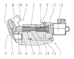
- FIG. 1 a sectional view of a control arrangement of a hydrostatic module according of the invention
- FIG. 2 a sectional view of a first refinement of the control arrangement according to the invention according to FIG. 1 , and
- FIG. 3 a sectional view of a second refinement of the control arrangement according to the invention according to FIG. 1 .
- FIG. 1 to FIG. 3 each show a control arrangement 1 , 1 ′, 1 * according to the invention, which are used to control a hydraulic adjusting cylinder (diagrammatically shown in FIG. 2 ), the control arrangement being disposed radially spaced apart from and tangential with respect to the pivot axis of a yoke 5 of a hydrostatic module, and being operatively connected to the yoke 5 by means of a pivot lever.
- the yoke 5 Through the pivoting of the yoke 5 by the adjusting cylinder, the displacement volume of at least one axial piston machine is adjusted.
- the hydrostatic module as described in DE 10 2008 002 140 A1, for example, which comprises two band axis motors that are hydraulically coupled with one another.
- the cylinder blocks of these two band axis motors are disposed in the pivotable yoke 5 offset to one another in reference to a common pivot axis.
- One of the band axis motors functions as a hydrostatic pump, and the other band axis motor functions as a hydrostatic motor, so that the hydrostatic module forms a steplessly adjustable hydrostatic transmission.
- the control arrangement 1 comprises a position regulating valve 2 in the form of an electromagnetically controllable hydraulic proportional valve having a control piston 3 , by means of the axial position of which the adjusting pressure difference acting on the adjusting piston of the adjusting cylinder can be set, and a non-positive locking mechanical return device 4 , by means of which the pivoting position of the yoke 5 can be transferred to the control piston 3 of the position regulating valve 2 .
- the position regulating valve 2 is disposed axially parallel to the adjusting cylinder and disposed radially spaced apart from the pivot axis of the yoke 5 .
- the mechanical return device 4 comprises an axially movable, guided sensing piston 6 and a return spring 7 in the form of a helical spring, which are disposed coaxially and axially adjacent to the position regulating valve 2 .
- the sensing piston 6 thereby rests against a feedback surface 8 eccentrically disposed on the yoke 5 with respect to the pivot axis and is operatively connected to the control piston 3 of the position regulating valve 2 by means of the return spring 7 .
- the feedback surface 8 is formed on a component 9 that is attached to the yoke 5 removable, and therefore easily replaced.
- the sensing piston 6 is in contact with the feedback surface 8 of the yoke 5 so that, that piston can slide by means of a smooth anti-friction surface 11 disposed on the outer end 10 of that sensing piston, and is guided in a bore 14 of a base plate 15 of the hydrostatic module, in which the bearings of the yoke 5 are incorporated so that the sensing piston can slide in an axial direction.
- the return spring 7 is guided in a blind hole 12 of the sensing piston 6 on one side, and on a spring cap 13 centered on the control piston 3 of the position regulating valve 2 on the other side.
- the position regulating valve 2 has a cartridge design and is disposed in a stepped section of the same bore 14 .
- the electromagnet 16 of the position regulating valve 2 is disposed on the side facing away from the sensing piston 6 as well as the return spring 7 and is operatively connected to the control piston 3 of the position regulating valve 2 by means of an anchor pin 17 .
- the electromagnet 16 When a specific pivoting position is to be set starting from a resting position of the yoke 5 , the electromagnet 16 is energized with a specific control current and a specific control force is thereby generated, which is transferred to the control piston 3 of the position regulating valve 2 by means of the anchor pin 17 .
- the control piston 3 is hereby displaced against the return force of the return spring 7 in the direction of the sensing piston 6 , and this sensing piston frees openings along its control edges for connecting a high-pressure line and a low-pressure line with the two pressure chambers of the adjusting cylinder.
- the adjusting piston of the adjusting cylinder is thereby axially displaced and the yoke 5 is pivoted by means of the pivot lever in the desired manner according to the indicated pivot arrow 18 .
- This pivoting movement is registered by means of the sensing piston 6 abutting the feedback surface 8 of the yoke 5 and returned to the control piston 3 of the position regulating valve 2 by means of thereby higher tensioned return spring 7 .
- the control piston 3 is thereby pushed far enough back in the direction of the electromagnet 16 , and the effective adjusting pressure difference acting on the adjusting piston of the adjusting cylinder is sufficiently reduced until a balance of forces between the magnetic force acting on the anchor pin 17 and the spring force of the return spring 7 has been reached.
- the components of the control arrangement 1 are matched to one another in such a way that the respective equilibrium point of the control piston 3 of the position regulating valve 2 corresponds to the desired pivoting position of the yoke 5 .
- the pivoting position of the yoke 5 correlating to a specific magnetic force or to the corresponding control current of the electromagnet 16 is thereby automatically adjusted with a high degree of precision by means of the return device 4 . Imprecisions that arise in the known control arrangements as a result of the return of the control position of the adjusting cylinder to the position regulating valve are thereby eliminated in the control arrangement 1 according to the invention.
- a first further development of the control arrangement 1 ′ according to FIG. 2 differs from what is otherwise the same design of the control arrangement 1 according to FIG. 1 in that the sensing piston 6 ′ is now in contact with the feedback surface 8 of the yoke 5 by means of a ball 20 at the outer end 10 of that sensing piston, the ball being rotatably mounted in a spherical indentation 19 such that the sensing piston can rotate. This results in a lower-friction, and therefore more precise, return of the pivoting position of the yoke 5 to the position regulating valve 2 .
- a second further development of the control arrangement 1 * according to the invention according to FIG. 3 differs from what is otherwise the same design of the control arrangement 1 according to FIG. 1 in that the sensing piston 6 * is now in contact with feedback surface 8 of the yoke 5 by means of a roller 22 at the outer end of that sensing piston 10 , the roller being rotatably mounted about an axis 21 oriented parallel to the pivot axis of the yoke 5 such that the sensing piston can roll.
- This also results in a lower-friction, and therefore more precise, return of the pivoting position of the yoke 5 to the position regulating valve 2 as compared with the sliding contact between the sensing piston 6 and the feedback surface 8 of the control arrangement 1 according to FIG. 1 .
Landscapes
- Engineering & Computer Science (AREA)
- General Engineering & Computer Science (AREA)
- Mechanical Engineering (AREA)
- Physics & Mathematics (AREA)
- Fluid Mechanics (AREA)
- Reciprocating Pumps (AREA)
- Hydraulic Motors (AREA)
Applications Claiming Priority (4)
| Application Number | Priority Date | Filing Date | Title |
|---|---|---|---|
| DE102011006102A DE102011006102A1 (de) | 2011-03-25 | 2011-03-25 | Stellvorrichtung eines Hydrostatmoduls |
| DE102011006102.9 | 2011-03-25 | ||
| DE102011006102 | 2011-03-25 | ||
| PCT/EP2012/051765 WO2012130505A1 (de) | 2011-03-25 | 2012-02-02 | Stellvorrichtung eines hydrostatmoduls |
Publications (2)
| Publication Number | Publication Date |
|---|---|
| US20140000449A1 US20140000449A1 (en) | 2014-01-02 |
| US9518567B2 true US9518567B2 (en) | 2016-12-13 |
Family
ID=45567006
Family Applications (1)
| Application Number | Title | Priority Date | Filing Date |
|---|---|---|---|
| US14/006,350 Active 2033-01-13 US9518567B2 (en) | 2011-03-25 | 2012-02-02 | Adjusting device of a hydrostatic module |
Country Status (7)
| Country | Link |
|---|---|
| US (1) | US9518567B2 (de) |
| EP (1) | EP2689132B1 (de) |
| JP (1) | JP2014511963A (de) |
| KR (1) | KR20140012685A (de) |
| CN (1) | CN103443456B (de) |
| DE (1) | DE102011006102A1 (de) |
| WO (1) | WO2012130505A1 (de) |
Cited By (1)
| Publication number | Priority date | Publication date | Assignee | Title |
|---|---|---|---|---|
| US10519939B2 (en) * | 2016-12-09 | 2019-12-31 | Robert Bosch Gmbh | Hydrostatic axial piston machine |
Families Citing this family (6)
| Publication number | Priority date | Publication date | Assignee | Title |
|---|---|---|---|---|
| AU2014270792B2 (en) | 2013-05-22 | 2017-08-31 | Hydac Drive Center Gmbh | Axial piston pump having a swash-plate type construction |
| JP6248843B2 (ja) * | 2014-07-16 | 2017-12-20 | 株式会社豊田自動織機 | 可変容量型ピストンポンプ |
| CN104612926B (zh) * | 2015-01-19 | 2016-08-17 | 西安交通大学 | 一种采用端面凸轮传动的斜盘式轴向柱塞泵伺服变量机构 |
| BR112018009773B8 (pt) | 2015-11-15 | 2022-11-22 | Eaton Intelligent Power Ltd | Sistema de controle de bomba hidráulica |
| CH714321A1 (de) * | 2017-11-11 | 2019-05-15 | Liebherr Machines Bulle Sa | Verstellvorrichtung für eine Axialkolbenmaschine. |
| DE102020201171A1 (de) | 2020-01-31 | 2021-08-05 | Inline Hydraulik Gmbh | Verstelleinrichtung für eine Hydromaschine, Hydromaschine |
Citations (15)
| Publication number | Priority date | Publication date | Assignee | Title |
|---|---|---|---|---|
| DE2215891A1 (de) | 1971-03-29 | 1972-10-12 | Abex Corp., New York, N.Y. (V.St.A.) | Kolbenpumpe oder Motor mit veränderbarem Volumen |
| DE3346000A1 (de) | 1982-12-21 | 1984-06-28 | Linde Ag, 6200 Wiesbaden | Hydraulische stelleinrichtung fuer eine hydrostatische maschine |
| US5205201A (en) | 1991-08-19 | 1993-04-27 | Sauer, Inc. | Displacement control valve |
| DE19653165C1 (de) | 1996-12-19 | 1998-04-02 | Brueninghaus Hydromatik Gmbh | Verstelleinrichtung zur Verstellung des Fördervolumens einer Axialkolbenpumpe |
| DE10043451A1 (de) | 1999-09-03 | 2001-04-19 | Sauer Inc | Einteilige Proportionalregelung |
| DE10138554C1 (de) | 2001-08-06 | 2003-01-23 | Sauer Danfoss Neumuenster Gmbh | Steuerungseinrichtung für eine proportional verstellbare Hydraulikpumpe und Verstellpumpe für einen hydrostatischen Antrieb |
| US6883320B2 (en) | 2003-07-08 | 2005-04-26 | G. W. Lisk Company, Inc. | Control system regulating air flow to engine intake |
| JP2005201175A (ja) | 2004-01-16 | 2005-07-28 | Hitachi Constr Mach Co Ltd | 可変容量型斜板式液圧回転機 |
| US20070137475A1 (en) * | 2005-12-20 | 2007-06-21 | Sauer-Danfoss Inc. | Axial piston machine having an adjustable bent axis valve segment and a variable unit for the electrically proportional adjustment of the displacement |
| US20070277520A1 (en) | 2006-05-31 | 2007-12-06 | Sauer-Danfoss Inc | Hydraulic module with two integrated swashplate or oblique axis drive units |
| DE102008038435A1 (de) | 2007-08-20 | 2009-02-26 | Robert Bosch Gmbh | Hydraulisches System mit einer verstellbaren hydrostatischen Maschine |
| DE102008002140A1 (de) | 2008-06-02 | 2009-12-03 | Zf Friedrichshafen Ag | Hydromodul |
| DE102008031768A1 (de) | 2008-07-04 | 2010-01-07 | Alpha Fluid Hydrauliksysteme Müller GmbH | Regelanordnung für proportionale Winkelverstellung |
| US20100107626A1 (en) * | 2008-10-31 | 2010-05-06 | Caterpillar Inc. | Hydraulic variator with adjustable drum plates |
| US20140116242A1 (en) * | 2012-10-31 | 2014-05-01 | Robert Bosch Gmbh | Adjustment apparatus for a hydrostatic piston machine, and hydrostatic piston machine having an adjustment apparatus of this kind |
Family Cites Families (2)
| Publication number | Priority date | Publication date | Assignee | Title |
|---|---|---|---|---|
| DE10325842A1 (de) * | 2003-06-06 | 2005-01-05 | Brueninghaus Hydromatik Gmbh | Reversierbare Axialkolbenmaschine mit Längsverstellung |
| CN201433868Y (zh) * | 2009-05-31 | 2010-03-31 | 重庆江陵仪器厂 | 一种轴向变量柱塞泵 |
-
2011
- 2011-03-25 DE DE102011006102A patent/DE102011006102A1/de not_active Withdrawn
-
2012
- 2012-02-02 US US14/006,350 patent/US9518567B2/en active Active
- 2012-02-02 EP EP20120702815 patent/EP2689132B1/de active Active
- 2012-02-02 KR KR1020137025112A patent/KR20140012685A/ko not_active Withdrawn
- 2012-02-02 WO PCT/EP2012/051765 patent/WO2012130505A1/de not_active Ceased
- 2012-02-02 CN CN201280015188.6A patent/CN103443456B/zh not_active Expired - Fee Related
- 2012-02-02 JP JP2014500301A patent/JP2014511963A/ja active Pending
Patent Citations (22)
| Publication number | Priority date | Publication date | Assignee | Title |
|---|---|---|---|---|
| DE2215891A1 (de) | 1971-03-29 | 1972-10-12 | Abex Corp., New York, N.Y. (V.St.A.) | Kolbenpumpe oder Motor mit veränderbarem Volumen |
| US3733963A (en) | 1971-03-29 | 1973-05-22 | Abex Corp | Method and apparatus for controlling displacement of a variable volume pump or motor |
| DE3346000A1 (de) | 1982-12-21 | 1984-06-28 | Linde Ag, 6200 Wiesbaden | Hydraulische stelleinrichtung fuer eine hydrostatische maschine |
| US5205201A (en) | 1991-08-19 | 1993-04-27 | Sauer, Inc. | Displacement control valve |
| DE19653165C1 (de) | 1996-12-19 | 1998-04-02 | Brueninghaus Hydromatik Gmbh | Verstelleinrichtung zur Verstellung des Fördervolumens einer Axialkolbenpumpe |
| US6260468B1 (en) * | 1999-02-26 | 2001-07-17 | Sauer-Danfoss Inc. | Single-piece proportional control |
| DE10043451A1 (de) | 1999-09-03 | 2001-04-19 | Sauer Inc | Einteilige Proportionalregelung |
| DE10138554C1 (de) | 2001-08-06 | 2003-01-23 | Sauer Danfoss Neumuenster Gmbh | Steuerungseinrichtung für eine proportional verstellbare Hydraulikpumpe und Verstellpumpe für einen hydrostatischen Antrieb |
| US6837046B2 (en) | 2001-08-06 | 2005-01-04 | Sauer-Danfoss, Inc. | Control device for a proportionally adjustable hydraulic pump and a variable displacement pump for a hydrostatic drive |
| US6883320B2 (en) | 2003-07-08 | 2005-04-26 | G. W. Lisk Company, Inc. | Control system regulating air flow to engine intake |
| JP2005201175A (ja) | 2004-01-16 | 2005-07-28 | Hitachi Constr Mach Co Ltd | 可変容量型斜板式液圧回転機 |
| US20070137475A1 (en) * | 2005-12-20 | 2007-06-21 | Sauer-Danfoss Inc. | Axial piston machine having an adjustable bent axis valve segment and a variable unit for the electrically proportional adjustment of the displacement |
| DE102005060960B3 (de) | 2005-12-20 | 2007-06-28 | Sauer-Danfoss Gmbh & Co Ohg | Axialkolbenmaschine mit einem verstellbaren Schrägachsen-Ventilsegment und einer Verstelleinheit zur elektrisch proportionalen Verstellung des Schluckvolumens |
| US20070277520A1 (en) | 2006-05-31 | 2007-12-06 | Sauer-Danfoss Inc | Hydraulic module with two integrated swashplate or oblique axis drive units |
| DE102006025347B3 (de) | 2006-05-31 | 2007-12-27 | Sauer-Danfoss Gmbh & Co Ohg | Hydromodul mit zwei integrierten Schrägscheiben- oder Schrägachsentriebwerken |
| DE102008038435A1 (de) | 2007-08-20 | 2009-02-26 | Robert Bosch Gmbh | Hydraulisches System mit einer verstellbaren hydrostatischen Maschine |
| US20100199838A1 (en) | 2007-08-20 | 2010-08-12 | Clemens Krebs | Hydraulic system having an adjustable hydrostatic machine |
| DE102008002140A1 (de) | 2008-06-02 | 2009-12-03 | Zf Friedrichshafen Ag | Hydromodul |
| US20110061524A1 (en) * | 2008-06-02 | 2011-03-17 | Zf Friedrichshafen Ag | Hydraulic module |
| DE102008031768A1 (de) | 2008-07-04 | 2010-01-07 | Alpha Fluid Hydrauliksysteme Müller GmbH | Regelanordnung für proportionale Winkelverstellung |
| US20100107626A1 (en) * | 2008-10-31 | 2010-05-06 | Caterpillar Inc. | Hydraulic variator with adjustable drum plates |
| US20140116242A1 (en) * | 2012-10-31 | 2014-05-01 | Robert Bosch Gmbh | Adjustment apparatus for a hydrostatic piston machine, and hydrostatic piston machine having an adjustment apparatus of this kind |
Non-Patent Citations (3)
| Title |
|---|
| German Search Report Corresponding to 10 2011 006 102.9 mailed Feb. 10, 2012. |
| International Search Report Corresponding to PCT/EP2012/051765 mailed Apr. 18, 2012. |
| Written Opinion Corresponding to PCT/EP2012/051765 mailed Apr. 18, 2012. |
Cited By (1)
| Publication number | Priority date | Publication date | Assignee | Title |
|---|---|---|---|---|
| US10519939B2 (en) * | 2016-12-09 | 2019-12-31 | Robert Bosch Gmbh | Hydrostatic axial piston machine |
Also Published As
| Publication number | Publication date |
|---|---|
| DE102011006102A1 (de) | 2012-09-27 |
| JP2014511963A (ja) | 2014-05-19 |
| EP2689132A1 (de) | 2014-01-29 |
| WO2012130505A1 (de) | 2012-10-04 |
| EP2689132B1 (de) | 2015-05-06 |
| CN103443456B (zh) | 2015-12-09 |
| CN103443456A (zh) | 2013-12-11 |
| US20140000449A1 (en) | 2014-01-02 |
| KR20140012685A (ko) | 2014-02-03 |
Similar Documents
| Publication | Publication Date | Title |
|---|---|---|
| US9518567B2 (en) | Adjusting device of a hydrostatic module | |
| US9664184B2 (en) | Axial piston pump having a swash-plate type construction | |
| US20090288552A1 (en) | Hydrostatic axial piston machine | |
| US20090282824A1 (en) | Concrete agitating drum driving device | |
| US8167580B2 (en) | Axial piston machine with hydrostatic support of the holding-down device | |
| EP3569860B1 (de) | Hydraulikpumpe | |
| JP2004526916A (ja) | バリエータの油圧制御回路 | |
| KR101210733B1 (ko) | 굴삭기의 유압펌프용 레귤레이터 | |
| KR101702250B1 (ko) | 펌프 용적 제어 장치 | |
| CN103573573A (zh) | 静液压的轴向活塞式机器 | |
| JP3986584B2 (ja) | 静油圧式無段変速機 | |
| JP6114089B2 (ja) | 対向式斜板型ピストンポンプ・モータ | |
| US20200355171A1 (en) | Axialpiston machine | |
| JP2010053854A (ja) | 可変容量型ピストンポンプ | |
| US6739128B2 (en) | Electronically controlled dampener for hydrostatic transmission | |
| KR20190096804A (ko) | 유압 펌프 | |
| JP6688980B2 (ja) | 可変容量型ピストンポンプ | |
| US10302073B2 (en) | Axial hydraulic piston pump | |
| JP3372578B2 (ja) | トロイダル型無段変速機 | |
| JP3569759B2 (ja) | 可変容量型斜板式液圧機械 | |
| US11428103B2 (en) | Axial piston machine | |
| US6568311B2 (en) | Hydraulic motor with shift transmission | |
| JP4457746B2 (ja) | トロイダル型無段変速機 | |
| US20070101857A1 (en) | Hydrostatic piston machine with two hydraulic circuits | |
| JPH09177663A (ja) | 可変容量ポンプ |
Legal Events
| Date | Code | Title | Description |
|---|---|---|---|
| AS | Assignment |
Owner name: ZF FRIEDRICHSHAFEN AG, GERMANY Free format text: ASSIGNMENT OF ASSIGNORS INTEREST;ASSIGNORS:BREHMER, UDO;SCHRAFF, BERND;REHTANZ, ROLAND;SIGNING DATES FROM 20130708 TO 20130710;REEL/FRAME:031290/0566 |
|
| FEPP | Fee payment procedure |
Free format text: PAYOR NUMBER ASSIGNED (ORIGINAL EVENT CODE: ASPN); ENTITY STATUS OF PATENT OWNER: LARGE ENTITY |
|
| STCF | Information on status: patent grant |
Free format text: PATENTED CASE |
|
| MAFP | Maintenance fee payment |
Free format text: PAYMENT OF MAINTENANCE FEE, 4TH YEAR, LARGE ENTITY (ORIGINAL EVENT CODE: M1551); ENTITY STATUS OF PATENT OWNER: LARGE ENTITY Year of fee payment: 4 |
|
| MAFP | Maintenance fee payment |
Free format text: PAYMENT OF MAINTENANCE FEE, 8TH YEAR, LARGE ENTITY (ORIGINAL EVENT CODE: M1552); ENTITY STATUS OF PATENT OWNER: LARGE ENTITY Year of fee payment: 8 |