US9475133B2 - Cutting insert, cutting tool, and method of manufacturing machined product using the same - Google Patents
Cutting insert, cutting tool, and method of manufacturing machined product using the same Download PDFInfo
- Publication number
- US9475133B2 US9475133B2 US14/126,300 US201214126300A US9475133B2 US 9475133 B2 US9475133 B2 US 9475133B2 US 201214126300 A US201214126300 A US 201214126300A US 9475133 B2 US9475133 B2 US 9475133B2
- Authority
- US
- United States
- Prior art keywords
- cutting edge
- corner
- rake
- cutting
- major
- Prior art date
- Legal status (The legal status is an assumption and is not a legal conclusion. Google has not performed a legal analysis and makes no representation as to the accuracy of the status listed.)
- Active, expires
Links
- 238000005520 cutting process Methods 0.000 title claims abstract description 395
- 238000004519 manufacturing process Methods 0.000 title claims description 16
- 230000003247 decreasing effect Effects 0.000 claims description 5
- 238000000034 method Methods 0.000 description 16
- 230000008569 process Effects 0.000 description 14
- 238000003801 milling Methods 0.000 description 8
- NRTOMJZYCJJWKI-UHFFFAOYSA-N Titanium nitride Chemical compound [Ti]#N NRTOMJZYCJJWKI-UHFFFAOYSA-N 0.000 description 5
- 239000011248 coating agent Substances 0.000 description 5
- 238000000576 coating method Methods 0.000 description 5
- 238000003754 machining Methods 0.000 description 4
- 230000004048 modification Effects 0.000 description 4
- 238000012986 modification Methods 0.000 description 4
- 230000002093 peripheral effect Effects 0.000 description 4
- 238000005452 bending Methods 0.000 description 3
- 238000000227 grinding Methods 0.000 description 3
- 230000008901 benefit Effects 0.000 description 2
- 239000003086 colorant Substances 0.000 description 2
- 230000000694 effects Effects 0.000 description 2
- 230000001747 exhibiting effect Effects 0.000 description 2
- 238000010304 firing Methods 0.000 description 2
- 229910001018 Cast iron Inorganic materials 0.000 description 1
- RTAQQCXQSZGOHL-UHFFFAOYSA-N Titanium Chemical compound [Ti] RTAQQCXQSZGOHL-UHFFFAOYSA-N 0.000 description 1
- UQZIWOQVLUASCR-UHFFFAOYSA-N alumane;titanium Chemical compound [AlH3].[Ti] UQZIWOQVLUASCR-UHFFFAOYSA-N 0.000 description 1
- 230000002457 bidirectional effect Effects 0.000 description 1
- 238000007599 discharging Methods 0.000 description 1
- 239000000463 material Substances 0.000 description 1
- 230000009467 reduction Effects 0.000 description 1
- 239000010936 titanium Substances 0.000 description 1
- 229910052719 titanium Inorganic materials 0.000 description 1
Images


Classifications
-
- B—PERFORMING OPERATIONS; TRANSPORTING
- B23—MACHINE TOOLS; METAL-WORKING NOT OTHERWISE PROVIDED FOR
- B23B—TURNING; BORING
- B23B27/00—Tools for turning or boring machines; Tools of a similar kind in general; Accessories therefor
- B23B27/14—Cutting tools of which the bits or tips or cutting inserts are of special material
- B23B27/141—Specially shaped plate-like cutting inserts, i.e. length greater or equal to width, width greater than or equal to thickness
- B23B27/143—Specially shaped plate-like cutting inserts, i.e. length greater or equal to width, width greater than or equal to thickness characterised by having chip-breakers
-
- B—PERFORMING OPERATIONS; TRANSPORTING
- B23—MACHINE TOOLS; METAL-WORKING NOT OTHERWISE PROVIDED FOR
- B23C—MILLING
- B23C5/00—Milling-cutters
- B23C5/02—Milling-cutters characterised by the shape of the cutter
- B23C5/06—Face-milling cutters, i.e. having only or primarily a substantially flat cutting surface
-
- B—PERFORMING OPERATIONS; TRANSPORTING
- B23—MACHINE TOOLS; METAL-WORKING NOT OTHERWISE PROVIDED FOR
- B23C—MILLING
- B23C5/00—Milling-cutters
- B23C5/16—Milling-cutters characterised by physical features other than shape
- B23C5/20—Milling-cutters characterised by physical features other than shape with removable cutter bits or teeth or cutting inserts
- B23C5/202—Plate-like cutting inserts with special form
- B23C5/205—Plate-like cutting inserts with special form characterised by chip-breakers of special form
-
- B23C5/207—
-
- B—PERFORMING OPERATIONS; TRANSPORTING
- B23—MACHINE TOOLS; METAL-WORKING NOT OTHERWISE PROVIDED FOR
- B23C—MILLING
- B23C2200/00—Details of milling cutting inserts
- B23C2200/04—Overall shape
- B23C2200/0405—Hexagonal
- B23C2200/0411—Hexagonal irregular
-
- B—PERFORMING OPERATIONS; TRANSPORTING
- B23—MACHINE TOOLS; METAL-WORKING NOT OTHERWISE PROVIDED FOR
- B23C—MILLING
- B23C2200/00—Details of milling cutting inserts
- B23C2200/08—Rake or top surfaces
- B23C2200/085—Rake or top surfaces discontinuous
-
- B—PERFORMING OPERATIONS; TRANSPORTING
- B23—MACHINE TOOLS; METAL-WORKING NOT OTHERWISE PROVIDED FOR
- B23C—MILLING
- B23C2200/00—Details of milling cutting inserts
- B23C2200/20—Top or side views of the cutting edge
- B23C2200/203—Curved cutting edges
-
- B—PERFORMING OPERATIONS; TRANSPORTING
- B23—MACHINE TOOLS; METAL-WORKING NOT OTHERWISE PROVIDED FOR
- B23C—MILLING
- B23C2200/00—Details of milling cutting inserts
- B23C2200/28—Angles
- B23C2200/286—Positive cutting angles
-
- B—PERFORMING OPERATIONS; TRANSPORTING
- B23—MACHINE TOOLS; METAL-WORKING NOT OTHERWISE PROVIDED FOR
- B23C—MILLING
- B23C2210/00—Details of milling cutters
- B23C2210/04—Angles
- B23C2210/0407—Cutting angles
- B23C2210/0442—Cutting angles positive
- B23C2210/045—Cutting angles positive axial rake angle
-
- Y—GENERAL TAGGING OF NEW TECHNOLOGICAL DEVELOPMENTS; GENERAL TAGGING OF CROSS-SECTIONAL TECHNOLOGIES SPANNING OVER SEVERAL SECTIONS OF THE IPC; TECHNICAL SUBJECTS COVERED BY FORMER USPC CROSS-REFERENCE ART COLLECTIONS [XRACs] AND DIGESTS
- Y10—TECHNICAL SUBJECTS COVERED BY FORMER USPC
- Y10T—TECHNICAL SUBJECTS COVERED BY FORMER US CLASSIFICATION
- Y10T407/00—Cutters, for shaping
- Y10T407/22—Cutters, for shaping including holder having seat for inserted tool
- Y10T407/2268—Cutters, for shaping including holder having seat for inserted tool with chip breaker, guide or deflector
-
- Y—GENERAL TAGGING OF NEW TECHNOLOGICAL DEVELOPMENTS; GENERAL TAGGING OF CROSS-SECTIONAL TECHNOLOGIES SPANNING OVER SEVERAL SECTIONS OF THE IPC; TECHNICAL SUBJECTS COVERED BY FORMER USPC CROSS-REFERENCE ART COLLECTIONS [XRACs] AND DIGESTS
- Y10—TECHNICAL SUBJECTS COVERED BY FORMER USPC
- Y10T—TECHNICAL SUBJECTS COVERED BY FORMER US CLASSIFICATION
- Y10T407/00—Cutters, for shaping
- Y10T407/23—Cutters, for shaping including tool having plural alternatively usable cutting edges
- Y10T407/235—Cutters, for shaping including tool having plural alternatively usable cutting edges with integral chip breaker, guide or deflector
-
- Y—GENERAL TAGGING OF NEW TECHNOLOGICAL DEVELOPMENTS; GENERAL TAGGING OF CROSS-SECTIONAL TECHNOLOGIES SPANNING OVER SEVERAL SECTIONS OF THE IPC; TECHNICAL SUBJECTS COVERED BY FORMER USPC CROSS-REFERENCE ART COLLECTIONS [XRACs] AND DIGESTS
- Y10—TECHNICAL SUBJECTS COVERED BY FORMER USPC
- Y10T—TECHNICAL SUBJECTS COVERED BY FORMER US CLASSIFICATION
- Y10T409/00—Gear cutting, milling, or planing
- Y10T409/30—Milling
- Y10T409/303752—Process
- Y10T409/303808—Process including infeeding
Definitions
- the present invention relates to a cutting insert, a cutting tool, and a method of manufacturing a machined product using the same.
- an insert for use in a face milling process, an insert configured so that major cutting edges 24 and 25 are gradually inclined downward as separating from a corner part has been proposed (for example, refer to Japanese Unexamined Patent Publication No. 11-333616).
- rake surfaces 35 and 36 located correspondingly to the major cutting edges 24 and 25 are flat surface shaped surfaces as shown in FIG. 7 and the like. Therefore, the chips generated by the major cutting edges 24 and 25 are discharged after passing through the flat surface shaped rake surfaces 35 and 36 while following the inclined shape of the major cutting edges 24 and 25 . Consequently, the chips are less susceptible to stable curling, and hence the chips may extend long. As a result, there is a risk that surface quality of a target machining surface of a workpiece may be deteriorated due to chip biting between the insert and the workpiece.
- An object of the present invention is to provide a cutting insert and a cutting tool each having excellent chip discharge performance, as well as a method of manufacturing a machined product using the cutting insert and the cutting tool.
- a cutting insert includes: a polygonal shaped upper surface; a lower surface being identical in shape to the upper surface; a side surface connected to each of the upper surface and the lower surface; and an upper cutting edge located at an intersection of the upper surface and the side surface.
- the upper surface includes first and second corners adjacent to each other, and a rake surface continuous with the upper cutting edge.
- the upper cutting edge includes, sequentially from the first corner to the second corner, a corner cutting edge, a minor cutting edge inclined as separating from the corner cutting edge at a first inclination angle on a basis of a vertical plane perpendicular to a central axis extending between the upper and lower surfaces, and a major cutting edge inclined as separating from the minor cutting edge at a second inclination angle on the basis of the vertical plane so as to become more closer to the lower surface than the minor cutting edge.
- the rake surface includes a minor rake surface being continuous with the minor cutting edge and inclined as going inward at a first rake angle on the basis of the vertical plane so as to approach the lower surface, and a major rake surface being continuous with the major cutting edge and inclined as going inward at a second rake angle on the basis of the vertical plane so as to approach the lower surface.
- a cross section of the rake surface obtained by cutting an inwardly located end portion thereof along a direction of the central axis has a straight line shape or concave shape in a region crossing over at least the minor rake surface and the major rake surface.
- a cutting insert includes: a polygonal shaped upper surface; a lower surface being identical in shape to the upper surface; a side surface connected to each of the upper surface and the lower surface; and an upper cutting edge located at an intersection of the upper surface and the side surface.
- the upper surface includes first and second corners adjacent to each other, and a rake surface continuous with the upper cutting edge.
- the upper cutting edge includes, sequentially from the first corner to the second corner, a corner cutting edge, a minor cutting edge inclined as separating from the corner cutting edge at a first inclination angle on a basis of a vertical plane perpendicular to a central axis extending between the upper and lower surfaces, and a major cutting edge inclined as separating from the minor cutting edge at a second inclination angle on the basis of the vertical plane so as to become more closer to the lower surface than the minor cutting edge.
- the rake surface includes a minor rake surface being continuous with the minor cutting edge and inclined as going inward at a first rake angle on the basis of the vertical plane so as to approach the lower surface, and a major rake surface being continuous with the major cutting edge and inclined as going inward at a second rake angle on the basis of the vertical plane so as to approach the lower surface.
- the first rake angle of the minor rake surface is larger at an end portion thereof located closer to the second corner than that at an end portion thereof located closer to the first corner
- the second rake angle of the major rake surface is larger at an end portion thereof located closer to the first corner than that at an end portion thereof located closer to the second corner.
- a cutting tool includes the cutting insert of the foregoing embodiment, and a holder configured to attach the cutting insert thereto.
- a cutting section of the upper cutting edge extending from the first corner to the second corner in the cutting insert has a positive axial rake angle.
- a method of manufacturing a machined product according to an embodiment of the present invention includes: rotating the cutting tool according to the foregoing embodiment on a basis of a rotation axis of the holder; bringing the upper cutting edge of the cutting tool being rotated into contact with a surface of a workpiece; and separating the cutting tool from the workpiece.
- the upper cutting edge includes, sequentially from the first corner to the second corner, the corner cutting edge, the minor cutting edge inclined as separating from the corner cutting edge at the first inclination angle on the basis of the vertical plane perpendicular to the central axis extending between the upper and lower surfaces, and the major cutting edge inclined as separating from the minor cutting edge at the second inclination angle on the basis of the vertical plane so as to become more closer to the lower surface than the minor cutting edge.
- the cross section of the rake surface obtained by cutting the inwardly located end portion thereof along the direction of the central axis has the straight line shape or concave shape in the region crossing over at least the minor rake surface and the major rake surface.
- convex-shaped chips generated by the region corresponding to the minor cutting edge and the major cutting edge of the upper cutting edge can be deformed into the straight line shape or concave shape in the process of passing through the rake surface. Therefore, excellent chip discharge performance is exhibitable by stably curling the chips in the following chip discharge process.
- the upper cutting edge includes, sequentially from the first corner to the second corner, the corner cutting edge, the minor cutting edge inclined as separating from the corner cutting edge at the first inclination angle on the basis of the vertical plane perpendicular to the central axis extending between the upper and lower surfaces, and the major cutting edge inclined as separating from the minor cutting edge at the second inclination angle on the basis of the vertical plane so as to become more closer to the lower surface than the minor cutting edge.
- the first rake angle of the minor rake surface is larger at the end portion thereof located closer to the second corner than that at the end portion thereof located closer to the first corner
- the second rake angle of the major rake surface is larger at the end portion thereof located closer to the first corner than that at the end portion thereof located closer to the second corner.
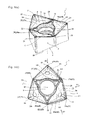
- FIG. 1( a ) is a perspective view of a cutting insert according to a first embodiment of the present invention
- FIG. 1( b ) is a plan view (top view) thereof;
- FIG. 2( a ) is a side view of the cutting insert shown in FIG. 1 , specifically a fragmentary view taken in the direction of an arrow X 1 ;
- FIG. 2( b ) is a fragmentary view taken in the direction of an arrow X 2 ;
- FIG. 2( c ) is a fragmentary view taken in the direction of an arrow X 3 ;
- FIG. 3 is a partially enlarged plan view (top view) of the cutting insert shown in FIG. 1 ;
- FIG. 4( a ) is a view of the cutting insert in FIG. 3 , taken from a first side surface, specifically a fragmentary side view taken in the direction of an arrow X 1 ;
- FIG. 4( b ) is a sectional view taken along line I-I therein;
- FIG. 4( c ) is a sectional view taken along line II-II therein;
- FIG. 5 is a partially enlarged plan view (top view) of a cutting insert according to a second embodiment of the present invention.
- FIG. 6( a ) is a sectional view showing a state that the cutting insert of FIG. 5 is cut away, specifically a sectional view taken along line a-a therein;
- FIG. 6( b ) is a sectional view taken along line b-b therein;
- FIG. 6( c ) is a sectional view taken along line c-c therein;
- FIG. 7( a ) is a perspective view of a cutting tool according to an embodiment of the present invention
- FIG. 7( b ) is a side view thereof
- FIG. 8( a ) is an enlarged side view of an attached state of the cutting insert in the cutting tool in FIG. 7 , specifically a view of the cutting insert taken from the side surface thereof;
- FIG. 8( b ) is a view of the cutting insert taken from the upper surface thereof;
- FIGS. 9( a ) to 9( c ) are process drawings showing a method of manufacturing a machined product according to a first embodiment of the present invention
- FIGS. 10( a ) to 10( c ) are process drawings showing a method of manufacturing a machined product according to a second embodiment of the present invention.
- FIG. 11 is a view showing a modification of a rake surface in the cutting insert in FIG. 1 , specifically a sectional view corresponding to FIG. 4( c ) .
- a cutting insert according to a first embodiment of the present invention is described in details below with reference to FIGS. 1 to 4 , taking the insert 1 having a hexagonal shape in a top view as an example.
- the insert 1 of the present embodiment generally includes an upper surface 2 having a polygonal shape (hexagonal shape), a lower surface 3 being identical in shape to the upper surface 2 , a side surface 4 connected to each of the upper surface 2 and the lower surface 3 , a through hole 6 (fitting hole) extending between the upper surface 2 and the lower surface 3 , an upper cutting edge 5 located at an intersection of the upper surface 2 and the side surface 4 , and a lower cutting edge 5 P located at an intersection of the lower surface 3 and the side surface 4 .
- the insert 1 may be configured so that the upper surface 2 measures 5-100 mm on each side and the upper and lower surfaces 2 and 3 respectively measure 3-100 mm thick.
- the through hole 6 of the present embodiment is located at a middle part on each of the upper surface 2 and the lower surface 3 .
- the insert 1 of the present embodiment has the hexagonal shape (approximately hexagonal shape) as shown in FIG. 1( b ) in the top view as described above.
- the phrase “top view” denotes a state that the insert 1 is viewed from the upper surface 2 .
- the insert 1 alternately has three major corners 21 (first to third major corners 21 a to 21 c ) as two or more major corners each having a first interior angle ⁇ 1, and three minor corners 22 (first to third minor corners 22 a to 22 c ) as two or more minor corners each having a second interior angle ⁇ 2 larger than the first interior angle ⁇ 1.
- the major corners 21 also respectively include a later-described first corner
- the minor corners also respectively include a later-described second corner.
- the first corner of the present embodiment corresponds to the first major corner 21 a and hence is described by using the same reference numeral as the first major corner 21 a .
- the second corner of the present embodiment corresponds to the first minor corner 22 a and hence is described by using the same reference numeral as the first minor corner 22 a.
- hexagonal shape includes somewhat deformation in such a range in which a certain function can be exhibited, without being limited to the case of a strict hexagonal shape (regular hexagon). That is, the hexagonal shape of the present embodiment includes the cases where, for example, individual sides or vertexes thereof have a slightly curved line shape.
- the upper cutting edge 5 is located over the entire periphery of the upper surface 2 , and includes first and second major cutting parts 5 a and 5 c (cutting sections) of identical shape which are extended from the single major corner 21 to the two adjacent minor corners 22 and 22 on both sides of the single major corner 21 . Therefore, a cutting process can be performed at each of the three major corners 21 by causing a bidirectional rotation for a right-handed operation and a left-handed operation. That is, the insert 1 of the present embodiment is usable as an insert substantially having the six major corners by using each of the three major corners 21 for the right-handed operation and the left-handed operation.
- the first interior angle ⁇ 1 is preferably an approximately right angle.
- the phrase “approximately right angle” denotes a substantially right angle.
- the approximately right angle in the present embodiment includes ones in the range of 90° ⁇ 3°.
- the first interior angle ⁇ 1 is preferably larger than 90°.
- the second interior angle ⁇ 2 is preferably set in the range of 140° to 150°.
- the lengths of the individual sides are preferably identical from the viewpoint of ensuring a large length of the cutting edges contributing to cutting while using all of the individual sides for the cutting process.
- the insert 1 of the present embodiment is the so-called negative type insert allowing both the upper surface 2 and the lower surface 3 to be respectively used as the surface that exhibits a rake function as shown in FIGS. 1( a ) and 2( a ) . Accordingly, when the cutting process is performed with the lower cutting edge 5 P, a part of the lower surface 3 is usable as a rake surface, and a part of the upper surface 2 , namely, a later-described upper mount part 26 included in the upper surface 2 is usable as a seating surface (mount part). That is, according to the insert 1 of the present embodiment, the upper surface 2 and the lower surface 3 have the same shape, thus making both the upper and lower surfaces usable for the cutting process.
- a part of the lower surface 3 namely, a flat surface shaped lower mount part 36 included in the lower surface 3 functions as a seating surface (mount part) for ensuring attachment to a holder 11 (refer to FIG. 8 ).
- the description of the upper surface 2 is applicable to the lower surface 3 .
- the upper surface 2 is the surface having a so-called rake function for discharging chips, and includes sequentially, as going inward from the upper cutting edge 5 , a rake surface 23 inclined toward the lower surface 3 , a connection surface 24 inclined toward the lower surface 3 , and the flat surface shaped upper mount part 26 substantially perpendicular to a central axis S 1 .
- the term “inward” denotes being located inside the insert 1 with respect to the upper cutting edge 5 and located closer to the through hole 6 (the central axis S 1 ).
- the phrase “central axis S 1 ” is the axis that extends between the upper surface 2 and the lower surface 3 , and serves as a rotation axis when the insert 1 is rotated in a top view.
- the rake surface 23 , the connection surface 24 and the upper mount part 26 are continuous with each other. This ensures a larger area of the upper mount part 26 , thereby improving attachment stability to the holder 11 . That is, for example, a distance from a top portion 26 t of the upper mount part 26 to a corner cutting edge 51 , namely, an amount of overhang can be reduced, thereby reducing a bending moment exerted on the insert 1 . Consequently it is capable of reducing the probability that the insert 1 is damaged during the cutting process.
- the rake surface 23 is the region mainly exhibiting the foregoing rake function and is continuous with the upper cutting edge 5 .
- the rake surface 23 is inclined downward from the upper cutting edge 5 toward the central axis S 1 , namely, at a rake angle ⁇ on the basis of a vertical plane S 1 b perpendicular to the central axis S 1 so as to approach the lower surface 3 (refer to FIG. 6 ).
- the rake angle ⁇ is located over the entire periphery of the insert 1 .
- the rake angle ⁇ is preferably set in the range of 10° to 30°.
- the rake surface 23 includes a corner rake surface 23 a , a minor rake surface 23 b and a major rake surface 23 c as shown in FIG. 3 .
- the minor rake surface 23 b is continuous with a later-described minor cutting edge 52 and is inclined downward as going inward, namely, at a first rake angle ⁇ 1 on the basis of the vertical plane S 1 b so as to approach the lower surface 3 .
- the major rake surface 23 c is continuous with a later-described major cutting edge 53 and is inclined downward as going inward, namely, at a second rake angle ⁇ 2 on the basis of the vertical plane S 1 b so as to approach the lower surface 3 .
- the region between the minor rake surface 23 b and the major rake surface 23 c is a connection surface having a gentle curved surface shape.
- a cross section of the rake surface 23 obtained by cutting an inwardly located end portion 23 A along the direction of the central axis S 1 has a straight line shape or concave shape in a region 23 B crossing over at least the minor rake surface 23 b and the major rake surface 23 c .
- the cross section of the rake surface 23 of the present embodiment has the straight line shape in the region 23 B.
- the insert 1 of the present embodiment has the foregoing configuration, and hence convex-shaped chips generated by the region corresponding to the minor cutting edge 52 and the major cutting edge 53 of the upper cutting edge 5 as described later can be deformed into the straight line shape or concave shape while the convex-shaped chips pass through the rake surface 23 . Therefore, the excellent chip discharge performance is exhibitable by stably curling the chips in the following chip discharge process.
- the foregoing cross section preferably has the straight line shape or concave shape in an approximately entire region of the minor rake surface 23 b and the major rake surface 23 c . According to this configuration, the excellent chip discharge performance is exhibitable under condition of a wide cutting depth.
- the inwardly located end portion 23 A of the rake surface 23 preferably has a straight line shape in a top view as shown in FIG. 3 . This contributes to enhancement of chip curling stability.
- a width W 1 of the rake surface 23 is preferably decreased from the first corner 21 a to the second corner 22 a in a top view as shown in FIG. 3 . That is, the rake surface 23 of the present embodiment has a relationship of W 1 a >W 1 b . According to this configuration, the excellent chip discharge performance is exhibitable under the condition of the wide cutting depth.
- the rake surface 23 further includes a land surface 231 located at an end portion thereof and located closer to the upper cutting edge 5 .
- the land surface 231 is substantially parallel to the vertical plane S 1 b . This configuration contributes to improved strength of the upper cutting edge 5 , thus allowing the insert 1 to be suitably used under machining conditions of so-called heavy-duty cutting.
- the upper mount part 26 is the flat surface shaped region located more inward than the rake surface 23 on the upper surface 2 as shown in FIG. 1 and the like.
- the upper mount part 26 generally has a polygonal shape, particularly a hexagonal shape in a top view in the insert 1 of the present embodiment.
- the concept of the phrase “polygonal shape” includes, for example, the configuration that a connection part between the sides is somewhat curved in such a range in which a predetermined operation advantage can be obtained, without being limited to the case of strictly having vertexes.
- the outer periphery of the through hole 6 is located inside a region surrounded by a straight line L 1 connecting top portions 26 t corresponding to the three major corners 21 of the upper mount part 26 in a top view as shown in FIG. 1( b ) .
- the phrase “top portions” denotes the regions corresponding to the vertexes of the polygonal shape, however, it may indicate regions in the vicinity of the vertexes which are respectively oval-shaped zones shown by dotted lines as shown in FIG. 1( b ) . This is also true for the following.
- the upper mount part 26 is preferably provided with three separate parts 26 a spaced apart from each other as shown in FIG. 1( b ) . Accordingly, when the insert 1 is attached to the holder 11 , the three separate parts 26 a of the insert 1 can individually be brought into contact with their corresponding contact surfaces of the holder 11 , thereby improving the attachment stability to the holder 11 . For example, even when the shape of the upper mount part 26 is subjected to deformation, such as bending, in the firing process in the manufacturing process of the insert 1 , the three separate parts 26 a , which are independent of one another, can be relatively strongly brought into contact with the contact surfaces of the holder 11 without requiring any additional process, such as grinding process.
- Each of the three separate parts 26 a has a triangular shape in a top view. Particularly, one top portion of the triangular shape of each of the separate parts 26 a is preferably most adjacent to the major corner 21 . This configuration further improves the attachment stability to the holder 11 .
- the lower mount part 36 of the lower surface 3 serves as the surface brought into contact with the holder 11 , and vice versa.
- the upper mount part 26 of the upper surface 2 is located on the most underside, namely, located closest to the lower surface 3 among any regions of the upper cutting edge 5 in a side view as shown in FIG. 2 .
- the phrase “side view” denotes a state that the insert 1 is viewed from the side surface 4 .
- This configuration reduces the probability that the chips generated by the upper cutting edge 5 collide with the upper mount part 26 during the cutting process, thereby reducing damage to the upper mount part 26 .
- a large space for generating the chips can be ensured and the chip discharge performance can be improved.
- the shape of the upper mount part 26 is subjected to deformation, such as bending, during a firing process in the manufacturing process of the insert 1 , it is difficult to shape the upper mount part 26 by grinding process when the upper mount part 26 is located more closer to the lower surface 3 than the upper cutting edge 5 .
- a stable contact with the contact surfaces of the holder 11 can be ensured by sloping the upper mount part 26 without requiring the grinding process.
- An end portion of the lower mount part 36 of the lower surface 3 which is located more closer to the central axis S 1 than the other end portion located closer to the lower cutting edge 5 P, is located closer to the upper surface 2 , namely, on the upper side on the basis of the vertical plane S 1 b .
- an outer peripheral region of the lower mount part 36 is located more outward than a middle region thereof on the lower surface 3 in the thickness direction of the insert 1 .
- the end portion of the lower mount part 36 located closer to the lower cutting edge 5 P can be relatively strongly brought into contact with the corresponding contact surface of the holder 11 , and the end portion thereof located closer to the central axis S 1 can be relatively weakly brought into contact with the corresponding contact surface of the holder 11 . Consequently, the attachment to the holder 11 via the end portion located closer to the lower cutting edge 5 P can be assisted by the end portion located closer to the central axis S 1 , thereby improving the attachment stability to the holder 11 .
- An inclination angle from the middle region to the outer peripheral region of the lower mount part 36 is preferably set in the range of 80° to 90° on the basis of the central axis S 1 .
- connection surface 24 is located between the rake surface 23 and the upper mount part 26 , and is connected to each of the rake surface 23 and the upper mount part 26 on the upper surface 2 as shown in FIGS. 1 and 3 .
- the connection surface 24 functions as a clearance for chips passing through the rake surface 23 , and also contributes to ensuring a large area of the upper mount part 26 .
- connection surface 24 is inclined downward as going inward, namely, at a connection angle ⁇ on the basis of the vertical plane S 1 b so as to approach the lower surface 3 (refer to FIG. 6 ).
- the connection angle ⁇ of the connection surface 24 is larger than both the first rake angle ⁇ 1 of the minor rake surface 23 b and the second rake angle ⁇ 2 of the major rake surface 23 c .
- a width W 2 of the connection surface 24 is preferably decreased from the first corner 21 a to the second corner 22 a in a top view as shown in FIG. 3 . That is, the connection surface 24 of the present embodiment has a relationship of W 2 a >W 2 b . According to this configuration, the foregoing excellent chip discharge performance is exhibitable under the condition of the wide cutting depth.
- the upper surface 2 may further include a concave part 25 located more closer to the lower surface 3 , namely, more downwardly than the upper amount part 26 on the circumference of the through hole 6 as shown in FIG. 1 .
- the three separate parts 26 a are spaced apart from one another with the through hole 6 and the concave part 25 interposed therebetween. This configuration allows each of the three separate parts 26 a to be more surely brought into contact with the corresponding contact surfaces of the holder 11 , thereby further improving the attachment stability to the holder 11 .
- the upper cutting edge 5 includes the corner cutting edge 51 , the minor cutting edge 52 and the major cutting edge 53 as shown in FIGS. 1 and 2 .
- the upper cutting edge 5 of the present embodiment includes the corner cutting edge 51 , the minor cutting edge 52 inclined downward as separating from the corner cutting edge 5 , namely, at a first inclination angle ⁇ 1 on the basis of the vertical plane S 1 b so as to approach the lower surface 3 , and the major cutting edge 53 inclined downward as separating from the minor cutting edge 52 , namely, at a second inclination angle ⁇ 2 on the basis of the vertical plane S 1 b so as to become more closer to the lower surface 3 than the minor cutting edge 52 .
- the corner cutting edge 51 , the minor cutting edge 52 and the major cutting edge 53 are located sequentially, for example, from the first major corner (first corner) 21 a of the three major corners 21 to the first minor corner (second corner) 22 a of the three minor corners 22 which is adjacent to the first major corner 21 a . Consequently, the chips generated by the minor cutting edge 52 and the major cutting edge 53 of the upper cutting edge 5 are formed into the convex shape as described above.
- the insert 1 is capable of having both low cutting resistance and excellent fracture resistance by combining the inclination configuration of the individual cutting edge regions of the upper cutting edge 5 with the major corner 21 having the first interior angle ⁇ 1 and the minor corner 22 having the second interior angle ⁇ 2 .
- the upper cutting edge 5 also includes the corner cutting edge 51 , the minor cutting edge 52 and the major cutting edge 53 , which are disposed sequentially from the first major corner (first corner) 21 a to another adjacent second minor corner 22 b of the three minor corners 22 . That is, the insert 1 of the present embodiment is configured to be usable for the right-handed and left-handed operations as described above.
- the corner cutting edge 51 is located at an intersection of a later-described major corner side surface 41 of the side surface 4 and the upper surface 2 as shown in FIG. 2 , and functions to suppress fracture of the upper cutting edge 5 due to cutting force applied thereto during the cutting process.
- the corner cutting edge 51 is parallel to the vertical plane S 1 b in the present embodiment.
- the corner cutting edge 51 preferably has a straight line shape in a top view in the present embodiment. In comparison with the case of a rounded corner, this configuration increases the width of the front end of the cutting edge in the top view, thereby ensuring high cutting edge strength. This permits reduction of the thickness of chips generated by the major corner 21 , thus making it possible to effectively suppress fracture, so-called edge chipping, of edge portions of a workpiece even during machining of cast iron that is a relatively brittle workpiece.
- the corner cutting edge 51 is preferably inclined at approximately 45° on the basis of a part of the upper cutting edge 5 adjacent thereto (for example, the minor cutting edge 52 ). This allows the insert 1 to be usable for both right-handed and left-handed operations.
- the minor cutting edge 52 is located closer to the corner cutting edge 51 in the intersection of a later-described first side surface 42 of the side surface 4 and the upper surface 2 . As shown in FIG. 1( b ) , the minor cutting edge 52 functions as first and second major cutting edge sections 5 a and 5 c together with the major cutting edge 53 .
- the minor cutting edge 52 is also the cutting edge, so-called flat drag, functioning mainly to improve the accuracy of a later-described finished surface 102 of a workpiece 100 .
- the minor cutting edge 52 has a straight line shape both in a top view and a side view as shown in FIGS. 2 and 3 .
- the minor cutting edge 52 is preferably inclined downward as separating from the corner cutting edge 51 , namely, at a first inclination angle ⁇ 1 on the basis of a vertical plane S 1 b so as to approach the lower surface 3 .
- This configuration reduces the cutting resistance of the minor cutting edge 52 during the cutting process.
- the first inclination angle ⁇ 1 of the minor cutting edge 52 may be oriented upward, namely, in a direction to separate from the lower surface 3 , on the basis of the vertical plane S 1 b.
- the first inclination angle ⁇ 1 of the minor cutting edge 52 is preferably set in the range of 3° to 15° toward the lower surface 3 .
- first inclination angle ⁇ 1 denotes an angle formed by the vertical plane S 1 b and a virtual extension line L 2 of the minor cutting edge 52 .
- virtual extension line L 2 denotes a straight line obtained by extending a tangential line at a start point of the minor cutting edge 52 , namely, an end portion of the minor cutting edge 52 located closer to the corner cutting edge 51 .
- the major cutting edge 53 is located more closer to the first minor corner 22 a than the minor cutting edge 52 in the intersection of the first side surface 42 and the upper surface 2 as shown in FIG. 2 .
- the major cutting edge 53 functions mainly to generate chips during the cutting process.
- the second inclination angle ⁇ 2 of the major cutting edge 53 is preferably set in the range of 7° to 19° toward the lower surface 3 .
- the phrase “second inclination angle ⁇ 2” denotes an angle formed by the vertical plane S 1 b and a virtual extension line L 3 of the major cutting edge 53 .
- the phrase “virtual extension line L 3 ” denotes a straight line obtained by extending a tangential line at a start point of the major cutting edge 53 , namely, an end portion of the major cutting edge 53 located closer to the minor cutting edge 52 .
- the major cutting edge 53 has a concave shape recessed toward the lower surface 3 in a side view. That is, the major cutting edge 53 is curved toward the lower surface 3 in the side view as shown in FIGS. 2( a ) and 4( a ) .
- the first inclination angle ⁇ 1 of the minor cutting edge 52 is preferably smaller than the second inclination angle ⁇ 2 of the major cutting edge 53 . This configuration ensures both high cutting strength on the minor cutting edge 52 and low cutting resistance on the major cutting edge 53 .
- connection part 54 of the major cutting edge 53 and the minor cutting edge 52 is preferably set to have a convex shape in a side view, namely, so as to be curved in the range of R1.0 to R10.0 in a direction to separate from the lower surface 3 (i.e. upwardly).
- the thickness of the insert 1 is decreased from the major corner (first corner) 21 a to the first minor corner (second corner) 22 a as shown in FIG. 2( a )
- the second interior angle ⁇ 2 of the second corner 22 a is larger than the first interior angle ⁇ 1 of the first corner 21 a as shown in FIG. 1( b ) , thereby ensuring high cutting edge strength in each of cutting edge regions of the upper cutting edge 5 .
- the lower cutting edge 5 P also includes a corner cutting edge 51 P, a minor cutting edge 52 P and a major cutting edge 53 P as shown in FIG. 2( a ) .
- the configurations of the corner cutting edge 51 P, the minor cutting edge 52 P and the major cutting edge 53 P are respectively identical to those of the corner cutting edge 51 , the minor cutting edge 52 and the major cutting edge 53 .
- the side surface 4 is the surface functioning as a so-called clearance part for reducing contact with the workpiece 100 .
- the side surface 4 is perpendicular to the upper surface 2 and the lower surface 3 , namely, perpendicular on the basis of the central axis S 1 .
- This configuration ensures the thickness of the insert 1 in a direction perpendicular to the central axis S 1 , and hence the insert 1 has excellent fracture resistance in comparison with an insert whose side surface 4 has a clearance angle between the upper surface 2 or the lower surface 3 .
- the side surface 4 connected to the hexagonal shaped upper surface 2 has, sequentially from the first major corner 21 a to the second major corner 21 b , a major corner side surface 41 , a first side surface 42 , a minor corner side surface 43 and a second side surface 44 as shown in FIG. 2( a ) .
- Both the first side surface 42 and the second side surface 44 are flat surfaces.
- the minor corner side surface 43 is a curved surface
- the major corner side surface 41 is a flat surface. This configuration corresponds to the fact that the corner cutting edge 51 located at the intersection of the major corner side surface 41 and the upper surface 2 has the straight line shape in the top view.
- the through hole 6 extends between the upper surface 2 and the lower surface 3 as shown in FIG. 1 and the like, and functions to fix the insert 1 to the later-described holder 11 . That is, a fitting screw 12 (fixing member) is inserted into the through hole 6 and is further screwed to the holder 11 . Thus, by fixing the insert 1 to the holder 11 in this manner, a cutting tool 10 is obtained.
- the central axis of the through hole 6 exists at the same position as the central axis S 1 .
- FIGS. 5 and 6 An insert according to a second embodiment of the present invention is described in details below with reference to FIGS. 5 and 6 .
- the basis configuration of the insert of the present embodiment is identical to that of the insert of the foregoing first embodiment. Therefore, the same components as those in the insert of the first embodiment are identified by the same reference numerals in these drawings and the description thereof is omitted. The following description is focused on portions that differ in configuration from the foregoing insert.
- a rake surface 23 in the insert 1 of the present embodiment includes a minor rake surface 23 b that is continuous with a minor cutting edge 52 and is inclined as going inward, namely, at a first rake angle ⁇ 1 on the basis of a vertical plane S 1 b so as to approach a lower surface 3 , and a major rake surface 23 c that is continuous with a major cutting edge 53 and is inclined as going inward, namely, at a second rake angle ⁇ 2 on the basis of the vertical plane S 1 b so as to approach the lower surface 3 as shown in FIGS. 5 and 6 .
- the first rake angle ⁇ 1 of the minor rake surface 23 b is large at an end portion 23 b 2 located more closer to a second corner 22 a than an end portion 23 b 1 located closer to a first corner 21 a
- the second rake angle ⁇ 2 of the major rake surface 23 c is large at an end portion 23 c 2 located more closer to the first corner 21 a than an end portion 23 c 1 located closer to the second corner 22 a .
- the insert 1 of the present embodiment is also capable of deforming convex-shaped chips generated by the region corresponding to the minor cutting edge 52 and the major cutting edge 53 of the upper cutting edge 5 into a straight line shape or concave shape while the convex-shaped chips pass through the rake surface 23 . Therefore, excellent chip discharge performance is exhibitable by stably curling the chips in the following chip discharge process.
- the line a-a is located between the end portion 213 b 1 and the end portion 23 b 2
- the line c-c is located between the end portion 23 c 1 and the end portion 23 c 2 .
- the first rake angle ⁇ 1 of the minor rake surface 23 b is increased from the first corner 21 a to the second corner 22 a
- the second rake angle ⁇ 2 of the major rake surface 23 c is increased from the second corner 22 a to the first corner 21 a .
- the first rake angle ⁇ 1 and the second rake angle ⁇ 2 are increased toward the connection part 23 C of the minor rake surface 23 b and the major rake surface 23 c , thereby achieving smoother chip discharge.
- a cutting tool according to an embodiment of the present invention is described in details below with reference to FIGS. 7 and 8 .
- the cutting tool 10 of the present embodiment includes a plurality of inserts 1 as described above, and the holder 11 configured to attach the plurality of inserts 1 thereto by using a fixing member.
- the holder 11 has a plurality of insert pockets 11 a at outer peripheral front ends thereof.
- the inserts 1 are respectively attached to outer peripheral positions in the insert pockets 11 a . Specifically, when the cutting tool 10 is rotated in an arrowed direction A in FIG. 7( a ) , the inserts 1 are attached so that the upper surface (rake surface) 2 is oriented forward in the arrowed direction A as the rotation direction, and the major cutting edge 53 is located at the outermost periphery of the holder 11 .
- the plurality of inserts 1 are respectively fixed to the holder 11 by inserting the fitting screw 12 (fixing member) into each of the through holes 6 of the plurality of inserts 1 , and by screwing the fitting screw 12 to the holder 11 .
- each of the inserts 1 is attached to the holder 11 in a state that the first major cutting section 5 a of the upper cutting edge 5 extending from the first major corner (first corner) 21 a to the first minor corner (second corner) 22 a adjacent thereto has a positive axial rake angle ⁇ a, and the non-cutting section 5 b of the upper cutting edge 5 extending from the first minor corner 22 a to the second major corner 21 b adjacent thereto has a negative axial rake angle ⁇ b on the basis of the parallel plane S 2 a parallel to a rotation axis S 2 of the holder 11 .
- the first major cutting section 5 a includes the minor cutting edge 52 and the major cutting edge 53 , and has a positive axial rake angle ⁇ a both in the minor cutting edge 52 and the major cutting edge 53 in the present embodiment.
- the axial rake angle of the minor cutting edge 52 is preferably set in the range of 0° to 10°
- the axial rake angle of the major cutting edge 53 is preferably set in the range of 5° to 20°.
- the axial rake angle ⁇ a may be measured using a straight line L 4 obtained by extending a tangential line at a start point of the major cutting edge 53 , namely, an end portion thereof located closer to the minor cutting edge 52 .
- the axial rake angle ⁇ b may be measured using a straight line L 5 obtained by extending a tangential line at a start point of the non-cutting section 5 b , namely, an end portion thereof located closer to the first minor corner 22 a.
- each of the inserts 1 is also attached to the holder 11 in a state that a straight line L 6 connecting the first major corner 21 a and the second major corner 21 b of the upper cutting edge 5 has a negative axial rake angle ⁇ c.
- the entirety including the first major cutting section 5 a and the non-cutting section 5 b has a negative axial rake angle.
- the cutting tool 10 is obtained by attaching the inserts 1 to the holder 11 in the above manner.
- the workpiece 100 can be subjected to various kinds of cutting processes, such as the face milling process and a plunging milling process, as described later by rotating the cutting tool 10 in the arrowed direction A.
- a cut surface 101 can be formed by cutting the workpiece 100 with the first major cutting section 5 a of the insert 1
- a finished surface 102 can be formed by cutting the workpiece 100 with the minor cutting edge 52 .
- a setting is made so that the minor cutting edge 52 has a substantially parallel relationship with the vertical plane S 2 b perpendicular to the rotation axis S 2 of the holder 11 .
- the method of manufacturing a machined product according to the first or second embodiment includes rotating the cutting tool 10 of the foregoing embodiment on the basis of the rotation axis S 2 of the holder 11 ; bringing the upper cutting edge 5 of the cutting tool 10 being rotated into contact with a surface of the workpiece 100 ; and separating the cutting tool 10 from the workpiece 100 .
- the first and second embodiments are respectively described in details below.
- the method of manufacturing a machined product according to the present embodiment includes the following steps (i) to (iii). In the following, the order of these steps may be changed suitably unless otherwise stated.
- the step (i) includes: rotating the cutting tool 10 around the rotation axis S 2 of the holder 11 (cutting tool 10 ) in the arrowed direction A as shown in FIG. 9( a ) ; and bringing the cutting tool 10 near the workpiece 100 by moving the cutting tool 10 in an arrowed direction B.
- the step (ii) is to bring the upper cutting edge 5 of the cutting tool 10 being rotated into contact with the surface of the workpiece 100 as shown in FIG. 9( b ) .
- the step (ii) includes the following three substeps.
- the first substep is to allow the cutting tool 10 being rotated to move in an arrowed direction C that is the direction perpendicular to the rotation axis S 2 . Thereby, the workpiece 100 can be subjected to the face milling process.
- the second substep is to bring the first major cutting section 5 a of the upper cutting edge 5 extending from the first major corner 21 a to the first minor corner 22 a adjacent thereto in the cutting tool 10 being rotated, into contact with the surface of the workpiece 100 . Consequently, a target cutting surface of the workpiece 100 cut by being brought into contact with the first major cutting section 5 a becomes a cut surface 101 as shown in FIG. 9( b ) .
- the third substep is to bring the minor cutting edge 52 of the upper cutting edge 5 located between the first major corner 21 a and the second minor corner 22 b in the cutting tool 10 being rotated, into contact with the target cutting surface of the workpiece 100 formed by being brought into contact with the first major cutting section 5 a .
- the portion of the target cutting surface of the workpiece 100 cut by the first major cutting section 5 a in the foregoing second substep which remains without being directly cut by the first major cutting section 5 a , can be smoothed by the minor cutting edge 52 , resulting in the finished surface 102 as shown in FIG. 9( b ) .
- the step (iii) is to separate the cutting tool 10 from the workpiece 100 by moving the cutting tool 10 just as it is in an arrowed direction C as shown in FIG. 9( c ) .
- a machined product 110 which is obtained by cutting the workpiece 100 into the desired shape as shown in FIG. 9( c ) , is manufactured by being subjected to the foregoing individual steps.
- the major corner 21 of the upper cutting edge 5 used for the cutting process can be used by rotating the insert 1 by 120° with respect to the central axis S 1 .
- the single major corner 21 of the insert 1 is usable for a reverse-handed cutting process by rotating the cutting tool 10 in the opposite direction to the arrowed direction A.
- the present embodiment permits use as the insert substantially having the six major corners by using each of the three major corners 21 for the right-handed and left-handed operations.
- the minor cutting edge 52 in the first major cutting section 5 a functions as a cutting edge for forming the finished surface 102 .
- the above description of the upper cutting edge 5 is also true for the lower cutting edge 5 P.
- the workpiece 100 may be rotated while keeping the cutting tool 10 stationary.
- the cutting tool 10 and the workpiece 100 need to be closer to each other.
- the workpiece 100 may be brought near the cutting tool 10 .
- the workpiece 100 and the cutting tool 10 need to be separated from each other.
- the workpiece 100 may be separated from the cutting tool 10 being held at a predetermined position.
- the method of manufacturing a machined product according to the present embodiment includes the following steps (i) to (iii). In the following, the order of these steps may be changed suitably unless otherwise stated.
- the step (i) includes: rotating the cutting tool 10 around the rotation axis S 2 of the holder 11 (cutting tool 10 ) in an arrowed direction A as shown in FIG. 10( a ) ; and bringing the cutting tool 10 near the workpiece 100 by moving the cutting tool 10 in an arrowed direction D.
- the step (ii) is to bring the upper cutting edge 5 of the cutting tool 10 being rotated into contact with a surface of the workpiece 100 as shown in FIG. 10( b ) .
- the step (ii) includes the following three substeps.
- the first substep is to allow the cutting tool 10 being rotated to move in an arrowed direction D that is the direction parallel to the rotation axis S 2 . Thereby, the workpiece 100 can be subjected to the plunge milling process.
- the second substep is to bring the second major cutting section 5 c of the upper cutting edge 5 extending from the first major corner 21 a to the second minor corner 22 b adjacent thereto in the cutting tool 10 being rotated, into contact with the surface of the workpiece 100 . Consequently, a target cutting surface of the workpiece 100 cut by being brought into contact with the second major cutting section 5 c becomes a cut surface 101 as shown in FIG. 10( b ) .
- the third substep is to bring the minor cutting edge 52 of the upper cutting edge 5 located between the first major corner 21 a and the first minor corner 22 a in the cutting tool 10 being rotated, into contact with the target cutting surface of the workpiece 100 formed by being brought into contact with the second major cutting section 5 c .
- the portion of the target cutting surface of the workpiece 100 cut by the second major cutting section 5 c in the foregoing second substep which remains without being directly cut by the second major cutting section 5 c , can be smoothed by the minor cutting edge 52 , resulting in a finished surface 102 as shown in FIG. 10( b ) .
- the step (iii) is to separate the cutting tool 10 from the workpiece 100 by moving the cutting tool 10 in an arrowed direction E as shown in FIG. 10( c ) .
- a machined product 110 which is obtained by cutting the workpiece 100 into the desired shape as shown in FIG. 10( c ) , is manufactured by being subjected to the foregoing individual steps.
- the inserts 1 of the foregoing embodiments have the hexagonal shape (approximately hexagonal shape) in the top view as shown in FIG. 1( b ) .
- the present invention is applicable to different polygonal shapes, such as quadrangular shape and pentagonal shape. Even in such cases, the foregoing operation advantages are achievable by having the foregoing configurations.
- the upper surface 2 and the lower surface 3 of the inserts 1 are identical in shape.
- the upper surface 2 and the lower surface 3 may have different shapes.
- a configuration that ensures a large clearance angle of the side surface 4 corresponding to the upper cutting edge 5 may be employed to obtain a so-called one side insert for use in the cutting process with the upper cutting edge 5 of the upper surface 2 .
- This configuration is achievable by, for example, making the area of the lower surface 3 smaller than the area of the upper surface 2 .
- connection surface 24 is disposed between the rake surface 23 and the upper mount part 26 on the upper surface 2 .
- the inserts 1 may be configured to have a protruded surface between the rake surface 23 and the upper mount part 26 .
- the protruded surface is inclined upward from the upper cutting edge 5 to the central axis S 1 , namely, in a direction to depart from the lower surface 3 on the basis of the vertical surface S 1 b . According to this configuration, chips can be deformed in a small-diameter curl shape when the chips are discharged, thereby improving the chip discharge performance.
- the protruded surface is preferably disposed at portions corresponding to the three minor corners 22 .
- the rake surface 23 is preferably continuous with the upper mount part 26 at portions corresponding to the three major corners 21 , and is preferably continuous with the upper mount part 26 with the protruded surface interposed therebetween at portions corresponding to the three minor corners 22 .
- the inclination angle of the protruded surface is preferably set in the range of 40° to 70° in a direction to separate from the lower surface 3 on the basis of the vertical plane S 1 b.
- the rake surface 23 is configured to have the straight line shape in the region 23 B in the foregoing cross section.
- the rake surface 23 may be configured to have a concave shape in the region 23 B (refer to FIG. 11 ).
- the rake surface 23 has a relatively smooth surface shape.
- the portion of the rake surface 23 corresponding to the corner cutting edge 51 may have a convex part (not shown). According to this configuration, chips generated under low cutting depth conditions or low feed conditions can be curled in a relatively small size by the convex part, thus exhibiting excellent chip discharge performance during finish machining process or the like.
- the entirety of the convex part is preferably disposed so as to fall within the region of the rake surface 23 . Further, the highest portion of the convex part is preferably in a lower position than the upper cutting edge 5 .
- the inserts 1 configured so that the upper mount part 26 includes the three separate parts 26 a .
- the inserts 1 may employ a structure that connects the three separate parts 26 a at their respective portions adjacent to each other as far as a similar effect can be obtained.
- the upper surface 2 and the lower surface 3 may have different colors though not particularly mentioned in the inserts 1 of the foregoing embodiments.
- either the upper surface 2 or the lower surface 3 is preferably coated with gold-colored titanium nitride (TiN).
- TiN titanium nitride
- both the upper surface 2 and the lower surface 3 function as the rake surface, and hence an erroneous attachment of the inserts might occur.
- TiN titanium nitride
- a target coating surface of either the upper surface 2 or the lower surface 3 need not be entirely coated.
- a similar effect is obtainable by coating, for example, a part of the target coating surface (e.g., a portion other than the cutting edges) with TiN.
- the material used for the coating is not limited to TiN as far as one can recognize a color difference between the upper surface 2 and the lower surface 3 .
- the insert body is made of cemented carbide, it is also possible to employ bright reddish brown colored titanium carbonitride (TiCN), dark reddish brown colored titanium aluminum nitride (TiAlN), or the like.
- the upper surface 2 of the inserts 1 of the foregoing embodiments has the hexagonal shape
- the upper surface 2 may have any polygonal shape other than the hexagonal shape.
Landscapes
- Engineering & Computer Science (AREA)
- Mechanical Engineering (AREA)
- Milling Processes (AREA)
- Cutting Tools, Boring Holders, And Turrets (AREA)
Applications Claiming Priority (3)
| Application Number | Priority Date | Filing Date | Title |
|---|---|---|---|
| JP2011146250 | 2011-06-30 | ||
| JP2011-146250 | 2011-06-30 | ||
| PCT/JP2012/061391 WO2013001907A1 (ja) | 2011-06-30 | 2012-04-27 | 切削インサートおよび切削工具、並びにそれを用いた切削加工物の製造方法 |
Related Parent Applications (1)
| Application Number | Title | Priority Date | Filing Date |
|---|---|---|---|
| PCT/JP2012/061391 A-371-Of-International WO2013001907A1 (ja) | 2011-06-30 | 2012-04-27 | 切削インサートおよび切削工具、並びにそれを用いた切削加工物の製造方法 |
Related Child Applications (1)
| Application Number | Title | Priority Date | Filing Date |
|---|---|---|---|
| US15/299,868 Continuation US10464146B2 (en) | 2011-06-30 | 2016-10-21 | Cutting insert, cutting tool, and method of manufacturing machined product using the same |
Publications (2)
| Publication Number | Publication Date |
|---|---|
| US20140126974A1 US20140126974A1 (en) | 2014-05-08 |
| US9475133B2 true US9475133B2 (en) | 2016-10-25 |
Family
ID=47423813
Family Applications (2)
| Application Number | Title | Priority Date | Filing Date |
|---|---|---|---|
| US14/126,300 Active 2032-12-07 US9475133B2 (en) | 2011-06-30 | 2012-04-27 | Cutting insert, cutting tool, and method of manufacturing machined product using the same |
| US15/299,868 Active 2032-06-28 US10464146B2 (en) | 2011-06-30 | 2016-10-21 | Cutting insert, cutting tool, and method of manufacturing machined product using the same |
Family Applications After (1)
| Application Number | Title | Priority Date | Filing Date |
|---|---|---|---|
| US15/299,868 Active 2032-06-28 US10464146B2 (en) | 2011-06-30 | 2016-10-21 | Cutting insert, cutting tool, and method of manufacturing machined product using the same |
Country Status (5)
| Country | Link |
|---|---|
| US (2) | US9475133B2 (ja) |
| EP (1) | EP2727672B1 (ja) |
| JP (1) | JP5739995B2 (ja) |
| CN (1) | CN103619517B (ja) |
| WO (1) | WO2013001907A1 (ja) |
Cited By (3)
| Publication number | Priority date | Publication date | Assignee | Title |
|---|---|---|---|---|
| US20160375506A1 (en) * | 2014-06-02 | 2016-12-29 | Sumitomo Electric Hardmetal Corp. | Cutting insert and milling cutter |
| US20180065194A1 (en) * | 2011-05-31 | 2018-03-08 | Kyocera Corporation | Cutting insert, cutting tool, and method of manufacturing machined product using the same |
| US20210339321A1 (en) * | 2018-08-30 | 2021-11-04 | Mitsubishi Materials Corporation | Cutting insert and cutting edge replacement type cutting tool |
Families Citing this family (17)
| Publication number | Priority date | Publication date | Assignee | Title |
|---|---|---|---|---|
| JP5824526B2 (ja) | 2011-10-31 | 2015-11-25 | 京セラ株式会社 | 切削インサートおよび切削工具、並びにそれを用いた切削加工物の製造方法 |
| EP2774705B1 (en) * | 2011-10-31 | 2020-12-23 | Kyocera Corporation | Cutting insert, cutting tool, and method for manufacturing cutting workpiece using same |
| ES2657114T3 (es) * | 2011-11-25 | 2018-03-01 | Sumitomo Electric Hardmetal Corp. | Accesorio de corte indexable para fresado |
| JP6228229B2 (ja) * | 2013-11-20 | 2017-11-08 | 京セラ株式会社 | 切削インサート、切削工具及び切削加工物の製造方法 |
| US9289836B2 (en) * | 2014-01-09 | 2016-03-22 | Iscar, Ltd. | Double-sided indexable cutting insert and cutting tool therefor |
| WO2015156373A1 (ja) * | 2014-04-11 | 2015-10-15 | 株式会社タンガロイ | 切削インサート、刃先交換式切削工具のボデーおよび刃先交換式切削工具 |
| US10099294B2 (en) * | 2014-07-29 | 2018-10-16 | Kyocera Corporation | Cutting insert, cutting tool, and method for manufacturing machined product |
| JP6267349B2 (ja) * | 2014-08-27 | 2018-01-24 | 京セラ株式会社 | 切削インサートおよび切削工具並びに切削加工物の製造方法 |
| EP3059037B1 (en) * | 2015-02-20 | 2023-08-02 | Seco Tools Ab | Double-sided high feed milling insert, high feed milling tool and method |
| DE102016109452A1 (de) * | 2016-05-23 | 2017-11-23 | Hartmetall-Werkzeugfabrik Paul Horn Gmbh | Schneidplatte für ein Fräswerkzeug und Fräswerkzeug |
| CN109715328B (zh) * | 2016-10-14 | 2020-09-29 | 住友电工硬质合金株式会社 | 切削刀具 |
| EP3311941B1 (en) * | 2016-10-19 | 2021-10-06 | Seco Tools Ab | Turning insert |
| WO2019026698A1 (ja) * | 2017-08-02 | 2019-02-07 | 京セラ株式会社 | 切削インサート、切削工具及び切削加工物の製造方法 |
| KR102015290B1 (ko) * | 2017-11-14 | 2019-08-28 | 한국야금 주식회사 | 절삭 인서트 및 이를 장착한 절삭 공구 |
| EP3560638B1 (en) * | 2018-04-26 | 2021-01-13 | AB Sandvik Coromant | Turning insert |
| JP7119780B2 (ja) * | 2018-08-30 | 2022-08-17 | 三菱マテリアル株式会社 | 切削インサートおよび刃先交換式切削工具 |
| JP7119781B2 (ja) * | 2018-08-30 | 2022-08-17 | 三菱マテリアル株式会社 | 切削インサートおよび刃先交換式切削工具 |
Citations (25)
| Publication number | Priority date | Publication date | Assignee | Title |
|---|---|---|---|---|
| US5544984A (en) * | 1993-01-27 | 1996-08-13 | Sandvik Ab | Cutting insert with twisted chip surface |
| JPH08323510A (ja) * | 1995-06-01 | 1996-12-10 | Mitsubishi Materials Corp | スローアウェイチップ及びスローアウェイ式カッタ |
| US5807031A (en) | 1995-03-10 | 1998-09-15 | Mitsubishi Materials Corp. | Throw-away tip and throw-away type cutter |
| US5810521A (en) * | 1993-01-27 | 1998-09-22 | Sandvik Ab | Cutting insert with twisted chip surface |
| US5876154A (en) * | 1994-11-19 | 1999-03-02 | Komet Praezisionswerkzeuge Robert Bruening Gmbh | Cutting insert for chip forming machining of work pieces |
| JPH11333616A (ja) | 1998-05-06 | 1999-12-07 | Sandvik Ab | 割り出し可能なエンドミル用インサ―ト |
| US20010051077A1 (en) | 2000-05-23 | 2001-12-13 | Mitsubishi Materials Corporation | Throwaway insert and throwaway-type cutter |
| JP2003275920A (ja) * | 2002-03-20 | 2003-09-30 | Mitsubishi Materials Corp | スローアウェイチップおよびスローアウェイ式切削工具 |
| US20070003384A1 (en) * | 2005-06-30 | 2007-01-04 | Iscar Ltd. | Cutting Insert Having Cylindrically Shaped Side Surface Portions |
| US20070071559A1 (en) * | 2005-09-28 | 2007-03-29 | Seco Tools Ab | Milling insert and a milling tool |
| WO2007142224A1 (ja) | 2006-06-06 | 2007-12-13 | Mitsubishi Materials Corporation | 切削工具及び切削インサート |
| US20080304924A1 (en) * | 2007-06-05 | 2008-12-11 | Tord Engstrom | Indexable end-milling insert |
| DE102008016732B3 (de) * | 2008-03-31 | 2009-06-04 | Hartmetall-Werkzeugfabrik Paul Horn Gmbh | Schneidwerkzeug für spanende Bearbeitung von Werkstücken, sowie Halter für ein Schneidwerkzeug |
| US20090238649A1 (en) * | 2006-09-19 | 2009-09-24 | Jacek Kruszynski | Indexable insert and use of the indexable in a solid drill |
| US20100080662A1 (en) | 2007-04-01 | 2010-04-01 | Amir Satran | Cutting Insert |
| JP2010142948A (ja) * | 2008-12-17 | 2010-07-01 | Sandvik Intellectual Property Ab | 両面割出し可能正面切削インサート |
| US20100202839A1 (en) | 2009-02-12 | 2010-08-12 | Tdy Industries, Inc. | Double-sided cutting inserts for high feed milling |
| JP2010228053A (ja) * | 2009-03-27 | 2010-10-14 | Kyocera Corp | 切削インサートおよび切削工具 |
| WO2011024595A1 (ja) * | 2009-08-31 | 2011-03-03 | 京セラ株式会社 | 切削工具およびそれを用いた切削加工物の製造方法 |
| JP2011093043A (ja) | 2009-10-29 | 2011-05-12 | Kyocera Corp | 切削インサートおよび切削工具ならびに被削加工物の製造方法 |
| US8157489B2 (en) * | 2006-09-25 | 2012-04-17 | Sandvik Intellectual Property Ab | Tool for chip removing machining and a cutting insert therefor |
| EP2450139A1 (en) | 2009-06-29 | 2012-05-09 | Kyocera Corporation | Cutting insert, cutting tool, and manufacturing method for cut product using the same |
| US20140076117A1 (en) * | 2011-05-31 | 2014-03-20 | Kyocera Corporation | Cutting insert, cutting tool, and method of manufacturing machined product using the same |
| US20140314509A1 (en) * | 2011-10-31 | 2014-10-23 | Kyocera Corporation | Cutting insert, cutting tool, and method of producing machined product using the same |
| US20150190868A1 (en) * | 2014-01-09 | 2015-07-09 | Iscar, Ltd. | Double-Sided Indexable Cutting Insert and Cutting Tool Therefor |
Family Cites Families (4)
| Publication number | Priority date | Publication date | Assignee | Title |
|---|---|---|---|---|
| CN1154670A (zh) * | 1995-03-24 | 1997-07-16 | 伊斯卡有限公司 | 镶装刀片 |
| JPH1133616A (ja) | 1997-05-23 | 1999-02-09 | Nippon Steel Corp | 鋼帯の捲取温度制御装置 |
| KR101239036B1 (ko) * | 2011-01-17 | 2013-03-04 | 대구텍 유한회사 | 직각 가공용 절삭 인서트 및 이를 구비한 밀링 커터 |
| CN103492109B (zh) * | 2011-04-28 | 2016-10-19 | 京瓷株式会社 | 切削镶刀、切削工具以及使用切削工具切削加工物的方法 |
-
2012
- 2012-04-27 CN CN201280029982.6A patent/CN103619517B/zh active Active
- 2012-04-27 US US14/126,300 patent/US9475133B2/en active Active
- 2012-04-27 WO PCT/JP2012/061391 patent/WO2013001907A1/ja active Application Filing
- 2012-04-27 EP EP12803557.3A patent/EP2727672B1/en active Active
- 2012-04-27 JP JP2013522509A patent/JP5739995B2/ja active Active
-
2016
- 2016-10-21 US US15/299,868 patent/US10464146B2/en active Active
Patent Citations (30)
| Publication number | Priority date | Publication date | Assignee | Title |
|---|---|---|---|---|
| US5544984A (en) * | 1993-01-27 | 1996-08-13 | Sandvik Ab | Cutting insert with twisted chip surface |
| US5810521A (en) * | 1993-01-27 | 1998-09-22 | Sandvik Ab | Cutting insert with twisted chip surface |
| US5876154A (en) * | 1994-11-19 | 1999-03-02 | Komet Praezisionswerkzeuge Robert Bruening Gmbh | Cutting insert for chip forming machining of work pieces |
| US5807031A (en) | 1995-03-10 | 1998-09-15 | Mitsubishi Materials Corp. | Throw-away tip and throw-away type cutter |
| JPH08323510A (ja) * | 1995-06-01 | 1996-12-10 | Mitsubishi Materials Corp | スローアウェイチップ及びスローアウェイ式カッタ |
| JPH11333616A (ja) | 1998-05-06 | 1999-12-07 | Sandvik Ab | 割り出し可能なエンドミル用インサ―ト |
| US6196770B1 (en) | 1998-05-06 | 2001-03-06 | Sandvik Ab | Indexible cutting insert for end mills |
| JP2002046010A (ja) | 2000-05-23 | 2002-02-12 | Mitsubishi Materials Corp | スローアウェイチップ及びスローアウェイ式カッタ |
| US20010051077A1 (en) | 2000-05-23 | 2001-12-13 | Mitsubishi Materials Corporation | Throwaway insert and throwaway-type cutter |
| JP2003275920A (ja) * | 2002-03-20 | 2003-09-30 | Mitsubishi Materials Corp | スローアウェイチップおよびスローアウェイ式切削工具 |
| US20070003384A1 (en) * | 2005-06-30 | 2007-01-04 | Iscar Ltd. | Cutting Insert Having Cylindrically Shaped Side Surface Portions |
| US20070071559A1 (en) * | 2005-09-28 | 2007-03-29 | Seco Tools Ab | Milling insert and a milling tool |
| US20100221076A1 (en) | 2006-06-06 | 2010-09-02 | Mitsubishi Materials Corporation | Cutting tool and cutting insert |
| WO2007142224A1 (ja) | 2006-06-06 | 2007-12-13 | Mitsubishi Materials Corporation | 切削工具及び切削インサート |
| US20090238649A1 (en) * | 2006-09-19 | 2009-09-24 | Jacek Kruszynski | Indexable insert and use of the indexable in a solid drill |
| US8157489B2 (en) * | 2006-09-25 | 2012-04-17 | Sandvik Intellectual Property Ab | Tool for chip removing machining and a cutting insert therefor |
| US20100080662A1 (en) | 2007-04-01 | 2010-04-01 | Amir Satran | Cutting Insert |
| JP2010523352A (ja) | 2007-04-01 | 2010-07-15 | イスカーリミテッド | 切削インサート |
| US20080304924A1 (en) * | 2007-06-05 | 2008-12-11 | Tord Engstrom | Indexable end-milling insert |
| DE102008016732B3 (de) * | 2008-03-31 | 2009-06-04 | Hartmetall-Werkzeugfabrik Paul Horn Gmbh | Schneidwerkzeug für spanende Bearbeitung von Werkstücken, sowie Halter für ein Schneidwerkzeug |
| JP2010142948A (ja) * | 2008-12-17 | 2010-07-01 | Sandvik Intellectual Property Ab | 両面割出し可能正面切削インサート |
| US20100202839A1 (en) | 2009-02-12 | 2010-08-12 | Tdy Industries, Inc. | Double-sided cutting inserts for high feed milling |
| JP2010228053A (ja) * | 2009-03-27 | 2010-10-14 | Kyocera Corp | 切削インサートおよび切削工具 |
| EP2450139A1 (en) | 2009-06-29 | 2012-05-09 | Kyocera Corporation | Cutting insert, cutting tool, and manufacturing method for cut product using the same |
| WO2011024595A1 (ja) * | 2009-08-31 | 2011-03-03 | 京セラ株式会社 | 切削工具およびそれを用いた切削加工物の製造方法 |
| US20120128440A1 (en) * | 2009-08-31 | 2012-05-24 | Kyocera Corporation | Cutting tool and method of manufacturing machined product using the same |
| JP2011093043A (ja) | 2009-10-29 | 2011-05-12 | Kyocera Corp | 切削インサートおよび切削工具ならびに被削加工物の製造方法 |
| US20140076117A1 (en) * | 2011-05-31 | 2014-03-20 | Kyocera Corporation | Cutting insert, cutting tool, and method of manufacturing machined product using the same |
| US20140314509A1 (en) * | 2011-10-31 | 2014-10-23 | Kyocera Corporation | Cutting insert, cutting tool, and method of producing machined product using the same |
| US20150190868A1 (en) * | 2014-01-09 | 2015-07-09 | Iscar, Ltd. | Double-Sided Indexable Cutting Insert and Cutting Tool Therefor |
Non-Patent Citations (2)
| Title |
|---|
| Extended European Search Report Dated Feb. 6, 2015 for European Application No. 12803557.3. |
| International Search Report, PCT/JP2012/061391, Jun. 4, 2012, 5 pp. |
Cited By (6)
| Publication number | Priority date | Publication date | Assignee | Title |
|---|---|---|---|---|
| US20180065194A1 (en) * | 2011-05-31 | 2018-03-08 | Kyocera Corporation | Cutting insert, cutting tool, and method of manufacturing machined product using the same |
| US10442013B2 (en) * | 2011-05-31 | 2019-10-15 | Kyocera Corporation | Cutting insert, cutting tool, and method of manufacturing machined product using the same |
| US20160375506A1 (en) * | 2014-06-02 | 2016-12-29 | Sumitomo Electric Hardmetal Corp. | Cutting insert and milling cutter |
| US9884377B2 (en) * | 2014-06-02 | 2018-02-06 | Sumitomo Electric Hardmetal Corp. | Cutting insert and milling cutter |
| US20210339321A1 (en) * | 2018-08-30 | 2021-11-04 | Mitsubishi Materials Corporation | Cutting insert and cutting edge replacement type cutting tool |
| US12030128B2 (en) * | 2018-08-30 | 2024-07-09 | Mitsubishi Materials Corporation | Cutting insert and cutting edge replacement type cutting tool |
Also Published As
| Publication number | Publication date |
|---|---|
| EP2727672B1 (en) | 2020-04-15 |
| JPWO2013001907A1 (ja) | 2015-02-23 |
| WO2013001907A1 (ja) | 2013-01-03 |
| US20140126974A1 (en) | 2014-05-08 |
| US10464146B2 (en) | 2019-11-05 |
| EP2727672A4 (en) | 2015-03-11 |
| CN103619517B (zh) | 2016-04-06 |
| JP5739995B2 (ja) | 2015-06-24 |
| EP2727672A1 (en) | 2014-05-07 |
| CN103619517A (zh) | 2014-03-05 |
| US20170100787A1 (en) | 2017-04-13 |
Similar Documents
| Publication | Publication Date | Title |
|---|---|---|
| US10464146B2 (en) | Cutting insert, cutting tool, and method of manufacturing machined product using the same | |
| US10507536B2 (en) | Cutting insert, cutting tool, and method of producing machined product using the same | |
| US10058937B2 (en) | Cutting insert, cutting tool, and method of manufacturing machined product using the same | |
| US10442013B2 (en) | Cutting insert, cutting tool, and method of manufacturing machined product using the same | |
| US9889511B2 (en) | Cutting insert, cutting tool, and method of producing machined product using the same | |
| US8998542B2 (en) | Cutting insert, cutting tool, and method of manufacturing machined product using them | |
| US8979440B2 (en) | Cutting insert, cutting tool, and method of manufacturing machined product using them | |
| EP2495060B1 (en) | Cutting insert and cutting tool, and cut workpiece manufacturing method using same | |
| US8985915B2 (en) | Cutting insert, cutting tool, and method of manufacturing machined product using the same | |
| EP2474378B1 (en) | Cutting tool and production method for cut items using the same | |
| JP4729894B2 (ja) | インサートおよびスローアウェイ式切削工具 | |
| JP5639710B2 (ja) | 切削インサートおよび切削工具、並びにそれを用いた切削加工物の製造方法 | |
| US12030128B2 (en) | Cutting insert and cutting edge replacement type cutting tool |
Legal Events
| Date | Code | Title | Description |
|---|---|---|---|
| AS | Assignment |
Owner name: KYOCERA CORPORATION, JAPAN Free format text: ASSIGNMENT OF ASSIGNORS INTEREST;ASSIGNOR:KOGA, KENICHIROU;REEL/FRAME:031877/0382 Effective date: 20131210 |
|
| STCF | Information on status: patent grant |
Free format text: PATENTED CASE |
|
| MAFP | Maintenance fee payment |
Free format text: PAYMENT OF MAINTENANCE FEE, 4TH YEAR, LARGE ENTITY (ORIGINAL EVENT CODE: M1551); ENTITY STATUS OF PATENT OWNER: LARGE ENTITY Year of fee payment: 4 |
|
| MAFP | Maintenance fee payment |
Free format text: PAYMENT OF MAINTENANCE FEE, 8TH YEAR, LARGE ENTITY (ORIGINAL EVENT CODE: M1552); ENTITY STATUS OF PATENT OWNER: LARGE ENTITY Year of fee payment: 8 |