US9470781B2 - Radar device and a method for detecting a malfunction of a receiver channel of a radar device - Google Patents
Radar device and a method for detecting a malfunction of a receiver channel of a radar device Download PDFInfo
- Publication number
- US9470781B2 US9470781B2 US14/359,891 US201214359891A US9470781B2 US 9470781 B2 US9470781 B2 US 9470781B2 US 201214359891 A US201214359891 A US 201214359891A US 9470781 B2 US9470781 B2 US 9470781B2
- Authority
- US
- United States
- Prior art keywords
- signal
- control means
- oscillator
- receiver
- frequency
- Prior art date
- Legal status (The legal status is an assumption and is not a legal conclusion. Google has not performed a legal analysis and makes no representation as to the accuracy of the status listed.)
- Active, expires
Links
- 238000000034 method Methods 0.000 title claims description 18
- 230000007257 malfunction Effects 0.000 title claims description 10
- 230000005540 biological transmission Effects 0.000 claims abstract description 21
- 239000012634 fragment Substances 0.000 claims description 73
- 238000001228 spectrum Methods 0.000 claims description 4
- 238000001514 detection method Methods 0.000 abstract description 23
- 230000002950 deficient Effects 0.000 description 4
- 230000005284 excitation Effects 0.000 description 3
- 230000032683 aging Effects 0.000 description 2
- 230000003044 adaptive effect Effects 0.000 description 1
- 230000001427 coherent effect Effects 0.000 description 1
- 238000013016 damping Methods 0.000 description 1
- 230000007423 decrease Effects 0.000 description 1
- 230000001419 dependent effect Effects 0.000 description 1
- 238000013213 extrapolation Methods 0.000 description 1
- 238000001914 filtration Methods 0.000 description 1
- 230000001151 other effect Effects 0.000 description 1
- 230000003071 parasitic effect Effects 0.000 description 1
- 238000005476 soldering Methods 0.000 description 1
- 230000002123 temporal effect Effects 0.000 description 1
- 238000011144 upstream manufacturing Methods 0.000 description 1
Images


Classifications
-
- G—PHYSICS
- G01—MEASURING; TESTING
- G01S—RADIO DIRECTION-FINDING; RADIO NAVIGATION; DETERMINING DISTANCE OR VELOCITY BY USE OF RADIO WAVES; LOCATING OR PRESENCE-DETECTING BY USE OF THE REFLECTION OR RERADIATION OF RADIO WAVES; ANALOGOUS ARRANGEMENTS USING OTHER WAVES
- G01S13/00—Systems using the reflection or reradiation of radio waves, e.g. radar systems; Analogous systems using reflection or reradiation of waves whose nature or wavelength is irrelevant or unspecified
- G01S13/02—Systems using reflection of radio waves, e.g. primary radar systems; Analogous systems
-
- G—PHYSICS
- G01—MEASURING; TESTING
- G01S—RADIO DIRECTION-FINDING; RADIO NAVIGATION; DETERMINING DISTANCE OR VELOCITY BY USE OF RADIO WAVES; LOCATING OR PRESENCE-DETECTING BY USE OF THE REFLECTION OR RERADIATION OF RADIO WAVES; ANALOGOUS ARRANGEMENTS USING OTHER WAVES
- G01S7/00—Details of systems according to groups G01S13/00, G01S15/00, G01S17/00
- G01S7/02—Details of systems according to groups G01S13/00, G01S15/00, G01S17/00 of systems according to group G01S13/00
- G01S7/40—Means for monitoring or calibrating
- G01S7/4004—Means for monitoring or calibrating of parts of a radar system
- G01S7/4008—Means for monitoring or calibrating of parts of a radar system of transmitters
-
- G—PHYSICS
- G01—MEASURING; TESTING
- G01S—RADIO DIRECTION-FINDING; RADIO NAVIGATION; DETERMINING DISTANCE OR VELOCITY BY USE OF RADIO WAVES; LOCATING OR PRESENCE-DETECTING BY USE OF THE REFLECTION OR RERADIATION OF RADIO WAVES; ANALOGOUS ARRANGEMENTS USING OTHER WAVES
- G01S13/00—Systems using the reflection or reradiation of radio waves, e.g. radar systems; Analogous systems using reflection or reradiation of waves whose nature or wavelength is irrelevant or unspecified
- G01S13/02—Systems using reflection of radio waves, e.g. primary radar systems; Analogous systems
- G01S13/06—Systems determining position data of a target
- G01S13/08—Systems for measuring distance only
- G01S13/32—Systems for measuring distance only using transmission of continuous waves, whether amplitude-, frequency-, or phase-modulated, or unmodulated
- G01S13/36—Systems for measuring distance only using transmission of continuous waves, whether amplitude-, frequency-, or phase-modulated, or unmodulated with phase comparison between the received signal and the contemporaneously transmitted signal
- G01S13/38—Systems for measuring distance only using transmission of continuous waves, whether amplitude-, frequency-, or phase-modulated, or unmodulated with phase comparison between the received signal and the contemporaneously transmitted signal wherein more than one modulation frequency is used
-
- G—PHYSICS
- G01—MEASURING; TESTING
- G01S—RADIO DIRECTION-FINDING; RADIO NAVIGATION; DETERMINING DISTANCE OR VELOCITY BY USE OF RADIO WAVES; LOCATING OR PRESENCE-DETECTING BY USE OF THE REFLECTION OR RERADIATION OF RADIO WAVES; ANALOGOUS ARRANGEMENTS USING OTHER WAVES
- G01S13/00—Systems using the reflection or reradiation of radio waves, e.g. radar systems; Analogous systems using reflection or reradiation of waves whose nature or wavelength is irrelevant or unspecified
- G01S13/88—Radar or analogous systems specially adapted for specific applications
- G01S13/93—Radar or analogous systems specially adapted for specific applications for anti-collision purposes
- G01S13/931—Radar or analogous systems specially adapted for specific applications for anti-collision purposes of land vehicles
-
- G—PHYSICS
- G01—MEASURING; TESTING
- G01S—RADIO DIRECTION-FINDING; RADIO NAVIGATION; DETERMINING DISTANCE OR VELOCITY BY USE OF RADIO WAVES; LOCATING OR PRESENCE-DETECTING BY USE OF THE REFLECTION OR RERADIATION OF RADIO WAVES; ANALOGOUS ARRANGEMENTS USING OTHER WAVES
- G01S7/00—Details of systems according to groups G01S13/00, G01S15/00, G01S17/00
- G01S7/02—Details of systems according to groups G01S13/00, G01S15/00, G01S17/00 of systems according to group G01S13/00
- G01S7/40—Means for monitoring or calibrating
- G01S7/4004—Means for monitoring or calibrating of parts of a radar system
- G01S7/4021—Means for monitoring or calibrating of parts of a radar system of receivers
Definitions
- the invention relates to a radar device for transmitting and receiving a signal in a frequency band for target detection.
- the invention includes a control means, an oscillator, with an input of the oscillator being connected via a converter to the control means, with it being able to address the oscillator via control means in order to generate a signal, and with it being possible to tap the signal generated via the oscillator at an output of the oscillator, at least one transmission antenna for transmitting the signals provided at the output of the oscillator, with the transmission antenna being connected to the output of the oscillator, and at least one receiver channel for receiving a receiver signal, for processing the receiver signal, and for forwarding the processed receiver signal to the control means, with the receiver channel comprising at least one receiving antenna for receiving the receiver signal and a mixer for mixing the receiver signal with the signal provided at the output of the oscillator, and with the mixer being connected to the output of the oscillator.
- Such a radar device is known from the patent publication DE 100 50 278 B4. It can be used to determine, via a LFMSK-transmission method, the distance and/or relative speed of a vehicle in reference to an object.
- the abbreviation here represents Linear Frequency Modulated Shift Keying.
- FIG. 1 shows the control means 1 , the oscillator 2 , the transmission antenna 3 , the receiving antenna 4 , and the mixer 5 .
- the control means can address the oscillator 2 .
- an output of the control means 1 is connected to a digital-analog converter 9 , which converts a predetermined digital value into an analog voltage.
- each signal portion A, B, C, . . . . of the signal shows a sequence of signal fragments A i , B i , C i , . . . .
- First signal fragments A 1 , B 1 , C 1 , . . . of the various signal portions A, B, C, . . . of the signal show different frequencies f 1 A , f 1 B , f 1 C , . . . and follow each other.
- the first signal fragments A 1 , B 1 , C 1 , . . . are followed by additional signal fragments A i , B i , C i , . . . of the signal portion A, B, C, . . . of the signal, which also follow each other.
- the frequency f i A , f i B , f i C , . . . of the signal fragments A i , B i , C i , . . . of a signal portion A, B, C, . . . of the signals increases during one cycle either from one signal fragment to the next signal fragment by one frequency increment ⁇ f or decreases during the cycle from one signal fragment to the next signal fragment by the frequency increment ⁇ f. It is also possible for the frequency f i A , f i B , f i C , . . . of the signal fragments A i , B i , C i , . . . of a signal portion A, B, C, . . . to remain steady during a cycle.
- the signal fragments also called bursts, show for example a length of 25 ⁇ s.
- the frequency f i A , f i B , f i C , . . . within a signal fragment A i , B i , C i , . . . of an arbitrary signal portion A, B, C, . . . of the signal is constant and during a cycle, based on a frequency f 0 A , f 0 B , f 0 C , . . . of a signal fragment A 0 , B 0 , C 0 , . . . of a single portion A, B, C, . . .
- a cycle is also called upchirp, downchirp, or Doppler chirp.
- Upchirps, downchirps, and/or Doppler chirps are preferably transmitted alternating.
- the different signal portions A, B, C, . . . of the signal are nested, i.e. here the signal fragments A i , B i , C i , . . . of the various signal portions A, B, C, . . . follow each other in a preferably fixed sequence, as shown in FIG. 2 for an upchirp .
- the frequencies of the first signal fragments A, B, C, . . . of the various signal portions A, B, C, . . . are distinguished from each other by a difference which is very small in reference to the frequencies.
- the frequency increments ⁇ f are also very small in reference to the frequencies of the various signal portions A, B, C, . . . , when they are above or below zero.
- the signal generated by the oscillator 2 is transmitted by the transmitting antenna 3 .
- the signal transmitted by the transmitting antenna 3 may be reflected by one or more targets, and the reflections, generally mixed with signals of other sources, can be received by at least two receiving antennas 4 .
- the signals received by the receiving antennas 4 are called receiver signals.
- the receiver signals are first amplified with an amplifier 6 and mixed in the mixer 5 with the signal at the output of the oscillator 2 such that wavelets develop, which show a frequency portion in the basic band. From the wavelets, which are filtered via a band pass filter 7 , the distance and the relative speed of a target, which cause a reflection, are determined in the control means 1 , particularly from a Doppler shift and phasing, as disclosed in the patent publication DE 100 50 278 B4. For this purpose, the wavelets are digitized at the input of the control means via an analog-digital converter 8 .
- the incident angle of the reflections can be determined. The information gathered this way and additional information can then be forwarded to another processing step.
- calibration cycles have essentially two objectives:
- the calibration of the voltage controlled oscillator occurs in the radar device of the applicant via a calibration signal generated in the control means 1 , which is supplied to a mixer 5 instead of a receiver signal.
- the calibration signal is mixed with the signal generated by the voltage controlled oscillator 2 in the mixer 5 .
- the mixed signal is then forwarded via the receiver channel to the control means 1 and used for calibrating the voltage controlled oscillator 2 .
- the detection of a malfunction of a receiver channel of the radar devices is also possible.
- the detection of a malfunction is possible during operation, i.e. during the upchirps, the downchirps, or the Doppler chirps.
- the high frequency signal received by the receiver antenna 4 which shows the reflections of the transmitted signal of objects to be detected in the environment of the radar device, is supplied via an amplifier 6 to the mixer 5 .
- the mixer 5 by the (coherent) mixing with the signal generated by the voltage controlled oscillator 2 a basic band signal develops, with the progression of its amplitude in an ideal mixer exclusively being determined by the phasing of the receiver signal in reference to the signal generated by the voltage controlled oscillator.
- the output signal of a real mixer 5 includes, in addition to the above-mentioned mixing product, also a so-called parasitic portion, which is also called mixer bias.
- This mixer bias is dependent on the absolute frequency of the signal generated by the voltage controlled oscillator at 24 GHz. In the frequency band used showing 100 MHz and/or 200 MHz, approximately a linear dependency can be assumed. The precise parameters of this dependency are different, though, from one mixer 5 to the next mixer 5 due to parts and soldering tolerances of the high-frequency components, particularly the mixer diodes, being arbitrary and variable both quantitatively as well as qualitatively.
- the analog filtering following in the mixer is not only designed as a low pass filter for limiting the noise but also as a band pass filter 7 , in order to dampen the low-frequency mixer bias in the receiver signal.
- the damped portion of the mixer bias is present in the receiver signals and in this form it is the basis for detecting a channel failure. This detection occurs digitally, because the output signal of the band pass filter is already converted from analog to digital by an analog-digital converter 8 for the other signal processing means at a resolution of 12 Bit.
- the option known to the applicant of detecting a channel failure comprises here to estimate the mixer bias, which due to its low frequency changes only very slowly over time, using an adaptive algorithm.
- this algorithm yields an expected signal portion, it can be assumed that the portion of the receiver channel operates without malfunctions from the mixer 5 to the analog-digital converter 8 .
- a malfunction of a channel is very probable, for example by an interrupted contact or a defective part between the mixer 5 and the analog-digital converter 8 .
- the detection of a channel failure requires storage and computing capacities of the control means 1 , which must be provided in addition to the storage and computing capacities of the control means 1 for target detection because the detection of a channel failure occurs during target detection. This can be considered disadvantageous.
- the target detection in the frequency ranges of the mixer bias required a strong damping of the basic band signal in the receiver channels. This is counter productive for detecting a channel failure, because the mixer bias is here damped to such an extent that a functional receiver channel can erroneously be detected as being defective.
- the present invention was based on the objective to suggest a radar device, by which the detection of a channel failure is possible, which requires no additional storage or computing capacities, and in which the detection of a channel failure can occur regardless of any measures for detecting a target.
- the output of the oscillator is connected to the input of the control means and that the control means is suitable and provided to address the oscillator in order to generate first signal portions for the purpose of detecting a channel failure, which show signal fragments, with their frequencies being equivalent to a lower cut-off frequency of the frequency band and an upper cut-off frequency of a frequency band, with it being possible that the signal fragments with the lower cut-off frequency and the signal fragments with the upper cut-off frequency can be generated alternating. From the selection of the frequencies of the signal fragments the term cut-off frequency mode is deducted for an operation of the radar device according to the invention.
- the objective is further attained according to the invention such that the output of the oscillator is connected to an input of the control means and that the control means is suitable and embodied to address the oscillator for the purpose of detecting a channel failure in order to generate first signal portions, which show signal fragments with their frequencies being within the frequency band, with here the frequency of two successive signal fragments differing by more than 4 MHz.
- the signal fragments may show frequencies, which are used as support frequencies for calibrating the oscillator.
- the title of support frequency mode is deducted from the selection of the frequencies of the signal fragments for an operation of the radar device according to the invention.
- a radar device according to the invention may be operated in the cut-off frequency mode or in the support frequency mode.
- the control means of the radar device is advantageously suitable and embodied that it uses the first signal portion generated for the purpose of detecting a channel failure also for calibrating the oscillator in order to generate signals transmitted via the transmission antenna.
- the output of the oscillator is returned to the control means.
- the output signal of the oscillator can therefore be processed in the control means in order to determine the characteristic of the oscillator and perhaps, by way of adjusting the voltage emitted by the control device, adjust it with regards to a desired progression.
- a frequency counting method is used for calibrating the oscillator, which allows the adjustment of several frequencies in the 24 GHz-band, with it being required that each individual frequency is kept constant over a period of approximately one millisecond. During this period, an efficient counting occurs of the respective frequency in the 24 GHz-band equivalent to the voltages. For the calibration, here an adjustment and a subsequent counting of several so-called support frequencies, distributed over the frequency band, are necessary within one calibration cycle.
- the temporal arrangement of the support frequencies itself is irrelevant for the calibration. However, it allows that the support frequencies can be used for detecting the channel failure and/or the signal fragments of the first signal portion, which are transmitted for detecting a channel failure, are used as support frequencies.
- the goal of a suitable sequence of the signal fragments is an excitation of the receiver channels as strong as possible. This can occur either by a reflection of the (transmitted) frequency shift between two signal fragments of the signal portion transmitted to detect a channel failure to objects in the environment of the radar device (case 1 ) or, if no objects are present in the environment of the radar device, by different amplitudes of the mixer bias due to the various signal fragments of the signal portion transmitted to detect the channel failure (case 2 ).
- case 1 sets no particular requirements to the sequence of frequencies of the signal fragments of the signal portion transmitted to detect the channel failure
- sufficiently large frequency shifts must occur so that in the mixer bias sufficiently large amplitudes can be detected, i.e. sufficiently large dynamics are given in the mixer bias. Due to the fact that for typical transmission band widths of 100 MHz or 200 MHz an approximately linear progression exists between the amplitude of the mixer bias of a channel and the absolute frequency at 24 GHz, shifts between chronological signal fragments are desired as large as possible during one cycle in order to detect a channel failure and/or for calibration. Large shifts between chronological signal fragments during a cycle can be achieved by radar devices according to claim 1 and/or radar devices according to claim 2 .
- the radar device allows the detection of a channel failure and a calibration of the oscillator typically in a start-up phase of the radar device.
- the radar device and particularly the control means of the radar device are then embodied such that initially estimated voltage values are set for the upper and lower cut-off frequencies of the transmission frequency band.
- the frequency counting method allows measuring the frequencies in the transmission frequency band according to the voltages set. Voltages for all desired frequencies within the frequency band can be approximated by interpolation or extrapolation.
- the upper and the lower cut-off frequencies are transmitted preferably as an alternating sequence of 20 signal fragments. This ensures an excitation of the receiver channels with 19 frequency shifts of maximally permitted height.
- the radar device with the features according to claim 2 allows with regards to the calibration of the oscillator that the estimated voltage values for the frequencies are adjusted between the upper and the lower cut-off frequencies at the oscillator using the control means.
- the frequency of the signal fragments generated by the oscillator is measured by the frequency counting method.
- the detection of the characteristic of the oscillator can be achieved with the control means, allowing a compensation of the non-linearity of the characteristic of the oscillator.
- an adequate frequency sequence is also selected in the radar device according to claim 2 . For example, 21 frequencies of the signal fragments, evenly distributed over the transmission frequency band, can allow an excitation of the receiver channels with frequency shifts which are considerably higher than the frequency shifts developing during the cycles in which a target detection occurs.
- the radar device according to the invention can be suitable and embodied for the purpose of target detection, with here the control means addressing the oscillator such
- the control means of a radar device can be suitable and embodied to evaluate, after the transmission of the first signal portion, the receiver signal processed in the receiver channel and forwarded to the control means, in order to detect a malfunction of a receiver channel.
- the control means can further be suitable and embodied, in order to evaluate the receiver signal forwarded to the control means, for determining a mean value of the receiver signal, forwarded to the control means during a time interval, and minimum and maximum values of the receiver signal forwarded to the control means during a time interval to the receiver signal, forwarded to the control means.
- the control means can be suitable and embodied, in order to evaluate the receiver signal forwarded to the control means, for comparing the mean value and the minimum value and the maximum value with each other and/or with predetermined values, and particularly for forming differences between the mean value, the minimum value, and/or the maximum value, and for comparing them with predetermined values. This can be a first way to detect high dynamics of the mixer bias in the receiver signal.
- the control means can be suitable and embodied, in order to evaluate the receiver signal forwarded to the control means, for determining and analyzing shifts in the receiver signal forwarded to the control means at predetermined points of time during the transmission of the first signal portion.
- the predetermined points of time may be times, at which frequency shifts are given in the signal generated by the oscillator. This may be a second way to determine high dynamics of the mixer bias in the receiver signal.
- the control device of a radar device can be suitable and embodied, for evaluating the receiver signal forwarded to the control means, for determining and analyzing the frequency spectrum of the receiver signal forwarded to the control means during the transmission of the first signal portion. This may be a third way to detect high dynamics of the mixer bias in the receiver signal.
- the determination and analysis of the forwarded receiver signal and particularly the mixer bias in the forwarded receiver signal can then occur temporarily offset in reference to the target detection so that the same resources, particularly the same storage and computing resources of the control device, can be used for the detection of a malfunction of one of the receiver channels and for target detection.
- control means In order to detect a malfunction of a receiver channel of a radar device, it may occur that repeatedly the control means addresses the oscillator in order to generate a first signal portion and evaluates the receiver signal, processed in the receiver channel and forwarded to the control means, for the purpose of detecting a channel failure of one of the receiver channels.
- the control means can detect a channel failure when a mixer bias of the receiver signal, forwarded to the control means, shows very low dynamics during the transmission of a first signal section.
- FIG. 1 is a schematic illustration of a radar device according to prior art
- FIG. 2 is a signal process in a method according to prior art
- FIG. 3 is a schematic illustration of a radar device according to the invention.
- FIG. 4 is a signal progression in the cut-off frequency mode
- FIG. 5 is a signal progression in the support frequency mode
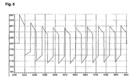
- FIG. 6 is a receiver signal forwarded in the cut-off frequency mode to the control means, without any targets in the environment of the radar device,
- FIG. 7 is a receiver signal forwarded in the support frequency mode to the control means without any targets in the environment of the radar device.
- the radar device according to the invention shown in FIG. 3 shows largely identical features to the radar device shown in FIG. 1 , therefore initially reference is made to the description of the radar device according to FIG. 1 .
- the radar device according to FIG. 3 differs essentially in a modified control means 1 , which is embodied according to the invention.
- the control means 1 shows a frequency counter 12 , which enables the radar device to measure the frequency at the output of the oscillator 2 according to the frequency counting method.
- a frequency splitter 11 is arranged upstream of the frequency counter 12 , which may be omitted depending on the embodiment of the frequency counter 12 . Due to the fact that the calibration occurs by the frequency counter and the output signal of the oscillator 2 , the transmission of a calibration signal from the control means to the receiver channel is not necessary, as shown in the radar device according to FIG. 1 .
- the radar device according to the invention shown in FIG. 3 is capable, both in the cut-off frequency mode ( FIG. 4 ) as well as in the support frequency mode ( FIG. 5 ) to generate first signal portions, which on the one side are used for calibrating the oscillator 2 of the radar device and on the other side allow the detection of a channel failure of a receiver channel.
- the first signal portion shown in FIG. 4 comprises several signal fragments.
- the signal fragments show a frequency which is either equivalent to the upper cut-off frequency or the lower cut-off frequencies of the frequency band selected for the radar device.
- the control means 1 controls the oscillator 2 with an interposed digital-analog converter 9 such that the signal fragments with the upper cut-off frequency alternate with the signal fragments with the lower cut-off frequency.
- the successive signal fragments show a frequency distance of 80 MHz, so that frequency shifts of 80 MHz shall occur during the change from one signal fragment to the subsequent signal fragment.
- the signal fragments preferably show a length of 1 ms.
- the first signal portion shown in FIG. 5 also comprises several signal fragments.
- the signal fragments show a frequency equivalent to the support frequencies selected for calibration.
- the control means 1 controls the oscillator 2 with the digital-analog converter 9 being interposed such that the frequency of one signal fragment to another signal fragment increases by at least 4 MHz. Greater frequency shifts are possible when another sequence of the signal fragments is selected.
- the signal fragments transmitted in the support frequency mode also show a length of preferably 1 ms.
- FIGS. 6 and 7 show the received signals repeatedly applied at the control means 1 and processed as measured in a real radar device. Both figures show a signal progression with high dynamics. Here it is possible to distinguish noise, as potentially developing in a defective channel, for the receiver signals according to FIGS. 6 and 7 with very simple and hardly expensive methods and means of signal processing. Accordingly, a very high reliability can be achieved for detecting channels failures.
- a method to detect channel failures to detect the mean value of the signal and its maximum and minimum value over the period shown.
- the differences between the mean value, the maximum value, and/or the minimum value amount to a multiple of the mean noise amplitude of a defective channel. As soon as a sufficiently large difference has been detected it can be assumed that the monitored receiver channel operates correctly.
Landscapes
- Engineering & Computer Science (AREA)
- Radar, Positioning & Navigation (AREA)
- Remote Sensing (AREA)
- Physics & Mathematics (AREA)
- Computer Networks & Wireless Communication (AREA)
- General Physics & Mathematics (AREA)
- Electromagnetism (AREA)
- Radar Systems Or Details Thereof (AREA)
Applications Claiming Priority (4)
| Application Number | Priority Date | Filing Date | Title |
|---|---|---|---|
| DE102011055693 | 2011-11-24 | ||
| DE102011055693.1 | 2011-11-24 | ||
| DE102011055693A DE102011055693A1 (de) | 2011-11-24 | 2011-11-24 | Radargerät und Verfahren zur Erkennung eines Ausfalls eines Empfangskanals eines Radargerätes |
| PCT/EP2012/073201 WO2013076126A1 (de) | 2011-11-24 | 2012-11-21 | Radargerät und verfahren zur erkennung eines ausfalls eines empfangskanals eines radargerätes |
Publications (2)
| Publication Number | Publication Date |
|---|---|
| US20140340254A1 US20140340254A1 (en) | 2014-11-20 |
| US9470781B2 true US9470781B2 (en) | 2016-10-18 |
Family
ID=47324079
Family Applications (1)
| Application Number | Title | Priority Date | Filing Date |
|---|---|---|---|
| US14/359,891 Active 2032-12-23 US9470781B2 (en) | 2011-11-24 | 2012-11-21 | Radar device and a method for detecting a malfunction of a receiver channel of a radar device |
Country Status (5)
| Country | Link |
|---|---|
| US (1) | US9470781B2 (de) |
| EP (1) | EP2783237B1 (de) |
| CN (1) | CN104024882B (de) |
| DE (1) | DE102011055693A1 (de) |
| WO (1) | WO2013076126A1 (de) |
Cited By (2)
| Publication number | Priority date | Publication date | Assignee | Title |
|---|---|---|---|---|
| US10234542B2 (en) * | 2015-09-30 | 2019-03-19 | Texas Instruments Incorporated | Measurement of transceiver performance parameters in a radar system |
| US20220236406A1 (en) * | 2017-05-05 | 2022-07-28 | Conti Temic Microelectronic Gmbh | Radar system with monitoring of the frequency position of a sequence of similar transmission signals |
Families Citing this family (27)
| Publication number | Priority date | Publication date | Assignee | Title |
|---|---|---|---|---|
| DE102013111512A1 (de) | 2013-10-18 | 2015-04-23 | Hella Kgaa Hueck & Co. | Radargerät und Verfahren zum Betreiben eines Radargerätes |
| DE102013111517A1 (de) | 2013-10-18 | 2015-04-23 | Hella Kgaa Hueck & Co. | Radargerät und Verfahren zum Betreiben eines Radargerätes |
| DE102013113806A1 (de) * | 2013-12-11 | 2015-06-11 | Hella Kgaa Hueck & Co. | Radarvorrichtung und Verfahren hierfür |
| DE102014014307A1 (de) * | 2014-09-25 | 2016-03-31 | Audi Ag | Verfahren zum Betrieb einer Mehrzahl von Radarsensoren in einem Kraftfahrzeug und Kraftfahrzeug |
| FR3030774B1 (fr) * | 2014-12-19 | 2017-01-20 | Thales Sa | Procede de determination de parametres d'un filtre de compression et radar multivoies associe |
| DE102015103149B4 (de) * | 2015-03-04 | 2024-06-06 | HELLA GmbH & Co. KGaA | Radarvorrichtung |
| KR102422396B1 (ko) * | 2015-09-01 | 2022-07-20 | 주식회사 에이치엘클레무브 | 선형 위상 어레이 안테나의 공간 보간 방법 및 보간 장치 |
| WO2017175190A1 (en) | 2016-04-07 | 2017-10-12 | Uhnder, Inc. | Adaptive transmission and interference cancellation for mimo radar |
| US10261179B2 (en) * | 2016-04-07 | 2019-04-16 | Uhnder, Inc. | Software defined automotive radar |
| US9846228B2 (en) | 2016-04-07 | 2017-12-19 | Uhnder, Inc. | Software defined automotive radar systems |
| WO2017187331A1 (en) | 2016-04-25 | 2017-11-02 | Uhnder, Inc. | Vehicle radar system with a shared radar and communication system |
| US9945935B2 (en) | 2016-04-25 | 2018-04-17 | Uhnder, Inc. | Digital frequency modulated continuous wave radar using handcrafted constant envelope modulation |
| US9772397B1 (en) | 2016-04-25 | 2017-09-26 | Uhnder, Inc. | PMCW-PMCW interference mitigation |
| US9753121B1 (en) | 2016-06-20 | 2017-09-05 | Uhnder, Inc. | Power control for improved near-far performance of radar systems |
| US10641866B2 (en) * | 2016-08-05 | 2020-05-05 | Texas Instruments Incorporated | Failure detection in a radar system |
| JP6815840B2 (ja) * | 2016-11-16 | 2021-01-20 | 株式会社デンソーテン | レーダ装置および物標検知方法 |
| US10670695B2 (en) | 2017-02-10 | 2020-06-02 | Uhnder, Inc. | Programmable code generation for radar sensing systems |
| WO2018146530A1 (en) | 2017-02-10 | 2018-08-16 | Uhnder, Inc. | Reduced complexity fft-based correlation for automotive radar |
| US11454697B2 (en) | 2017-02-10 | 2022-09-27 | Uhnder, Inc. | Increasing performance of a receive pipeline of a radar with memory optimization |
| US11105890B2 (en) | 2017-12-14 | 2021-08-31 | Uhnder, Inc. | Frequency modulated signal cancellation in variable power mode for radar applications |
| US11145146B2 (en) * | 2018-01-31 | 2021-10-12 | Mentor Graphics (Deutschland) Gmbh | Self-diagnosis of faults in an autonomous driving system |
| US11474225B2 (en) | 2018-11-09 | 2022-10-18 | Uhnder, Inc. | Pulse digital mimo radar system |
| IT201900002319A1 (it) * | 2019-02-18 | 2020-08-18 | Inxpect S P A | Sistema di rilevamento di oggetti in un ambiente |
| WO2020183392A1 (en) | 2019-03-12 | 2020-09-17 | Uhnder, Inc. | Method and apparatus for mitigation of low frequency noise in radar systems |
| US11513190B2 (en) * | 2019-05-31 | 2022-11-29 | Texas Instruments Incorporated | Methods and apparatus to test radar integrated circuits |
| CN112782674A (zh) * | 2019-11-07 | 2021-05-11 | 上海禾赛科技股份有限公司 | 激光雷达及其控制方法 |
| WO2021144711A2 (en) | 2020-01-13 | 2021-07-22 | Uhnder, Inc. | Method and system for intefrence management for digital radars |
Citations (18)
| Publication number | Priority date | Publication date | Assignee | Title |
|---|---|---|---|---|
| US325096A (en) | 1885-08-25 | And john coffin | ||
| US893125A (en) | 1903-07-17 | 1908-07-14 | Stromberg Carlson Telephone | Selective signaling system. |
| US4180816A (en) * | 1977-08-29 | 1979-12-25 | Nissan Motor Company, Limited | Testing circuit for radar-operated vehicle safety assurance systems |
| US4245221A (en) * | 1979-04-27 | 1981-01-13 | Rca Corporation | FM-CW Radar ranging system with automatic calibration |
| US4945360A (en) * | 1988-09-12 | 1990-07-31 | Messerschmitt-Boelkow-Blohm Gmbh | Radar altimeter |
| US5432516A (en) * | 1994-01-13 | 1995-07-11 | Armatron International, Inc. | Radar obstacle detection system with self test |
| US5867536A (en) | 1997-02-11 | 1999-02-02 | Hittite Microwave Corporation | Digital synchronization of broadcast frequency |
| US6278399B1 (en) * | 1999-02-22 | 2001-08-21 | Honda Giken Kogyo Kabushiki Kaisha | Radar apparatus and method for detecting malfunction of radar apparatus |
| EP1141744A1 (de) | 1998-11-11 | 2001-10-10 | Siemens Aktiengesellschaft | Verfahren zur detektion und korrektur von nichtlinearitäten hochfrequenter, spannungsgesteuerter oszillatoren |
| US6369747B1 (en) * | 1999-02-24 | 2002-04-09 | Honda Giken Kogyo Kabushiki Kaisha | Radar apparatus |
| US6414628B1 (en) * | 1999-02-05 | 2002-07-02 | Honda Giken Kogyo Kabushiki Kaisha | Method of detecting fault of radar apparatus using movement distance and radar apparatus for the same |
| JP2004171402A (ja) | 2002-11-21 | 2004-06-17 | Hitachi Ltd | 故障診断機能付信号処理装置 |
| US6825799B2 (en) * | 2003-03-04 | 2004-11-30 | Fujitsu Ten Limited | Radar apparatus equipped with abnormality detection function |
| DE10050278B4 (de) | 2000-10-10 | 2005-06-02 | S.M.S., Smart Microwave Sensors Gmbh | Verfahren und Vorrichtung zur Bestimmung von Abstand und Relativgeschwindigkeit eines entfernten Objektes |
| US7209074B2 (en) * | 2002-12-19 | 2007-04-24 | Trw Limited | Temperature compensation improvements in radar apparatus |
| JP2008032495A (ja) | 2006-07-27 | 2008-02-14 | Murata Mfg Co Ltd | レーダ装置 |
| US7427946B2 (en) * | 2005-04-12 | 2008-09-23 | Honda Motor Co., Ltd. | Object sensing apparatus |
| DE102009002143A1 (de) | 2009-04-02 | 2010-10-14 | Robert Bosch Gmbh | Vorrichtung und Verfahren zum Bestimmen einer Frequenz eines Signals |
Family Cites Families (14)
| Publication number | Priority date | Publication date | Assignee | Title |
|---|---|---|---|---|
| US4893125A (en) * | 1988-11-01 | 1990-01-09 | Delco Electronics Corporation | Vehicle diplex doppler near-obstacle detection system |
| JP3244792B2 (ja) * | 1992-08-04 | 2002-01-07 | 富士通株式会社 | 自己動作不良検知機能付自動車衝突防止レーダ |
| EP0655142B1 (de) * | 1992-08-14 | 1999-06-23 | Vorad Safety Systems, Inc. | Intelligenter totwinkelerfassungssensor |
| JP3639056B2 (ja) * | 1996-08-16 | 2005-04-13 | 富士通株式会社 | レーダ装置の故障判別装置 |
| KR100387212B1 (ko) * | 1999-09-21 | 2003-06-12 | 가부시키가이샤 무라타 세이사쿠쇼 | 듀플렉서 및 통신 장치 |
| EP1672381A1 (de) * | 2004-12-20 | 2006-06-21 | Siemens Aktiengesellschaft | Frequenzmodulierendes Dauerstrich-Radarsystem für Automatisierungskomponenten einer technischen Anlage |
| KR100703366B1 (ko) * | 2004-12-21 | 2007-04-03 | 삼성전자주식회사 | 무선 송수신기의 노이즈 제거 장치 |
| DE102005053442A1 (de) * | 2005-11-07 | 2007-05-10 | S.M.S Smart Microwave Sensors Gmbh | Verfahren zur Stabilisierung der Sendefrequenz eines Sendesignals und Radargerät |
| JP4855190B2 (ja) * | 2006-09-12 | 2012-01-18 | 富士通株式会社 | 位相同期発振器及びその制御方法 |
| JP2008172634A (ja) * | 2007-01-12 | 2008-07-24 | Denso Corp | Ad変換器の故障検出装置 |
| US7737885B2 (en) * | 2007-08-01 | 2010-06-15 | Infineon Technologies Ag | Ramp linearization for FMCW radar using digital down-conversion of a sampled VCO signal |
| US8429484B2 (en) * | 2009-04-16 | 2013-04-23 | Lockheed Martin Corporation | Digitized radar information redundancy method and system |
| DE102009047931B4 (de) * | 2009-10-01 | 2023-04-20 | HELLA GmbH & Co. KGaA | Verfahren und Vorrichtung zur Bestimmung von Abstand und Relativgeschwindigkeit wenigstens eines entfernten Objektes |
| KR101137038B1 (ko) * | 2010-01-05 | 2012-04-19 | 주식회사 만도 | 레이더 장치, 안테나 장치 및 데이터 획득 방법 |
-
2011
- 2011-11-24 DE DE102011055693A patent/DE102011055693A1/de active Pending
-
2012
- 2012-11-21 CN CN201280065687.6A patent/CN104024882B/zh active Active
- 2012-11-21 US US14/359,891 patent/US9470781B2/en active Active
- 2012-11-21 WO PCT/EP2012/073201 patent/WO2013076126A1/de active Application Filing
- 2012-11-21 EP EP12798210.6A patent/EP2783237B1/de active Active
Patent Citations (18)
| Publication number | Priority date | Publication date | Assignee | Title |
|---|---|---|---|---|
| US325096A (en) | 1885-08-25 | And john coffin | ||
| US893125A (en) | 1903-07-17 | 1908-07-14 | Stromberg Carlson Telephone | Selective signaling system. |
| US4180816A (en) * | 1977-08-29 | 1979-12-25 | Nissan Motor Company, Limited | Testing circuit for radar-operated vehicle safety assurance systems |
| US4245221A (en) * | 1979-04-27 | 1981-01-13 | Rca Corporation | FM-CW Radar ranging system with automatic calibration |
| US4945360A (en) * | 1988-09-12 | 1990-07-31 | Messerschmitt-Boelkow-Blohm Gmbh | Radar altimeter |
| US5432516A (en) * | 1994-01-13 | 1995-07-11 | Armatron International, Inc. | Radar obstacle detection system with self test |
| US5867536A (en) | 1997-02-11 | 1999-02-02 | Hittite Microwave Corporation | Digital synchronization of broadcast frequency |
| EP1141744A1 (de) | 1998-11-11 | 2001-10-10 | Siemens Aktiengesellschaft | Verfahren zur detektion und korrektur von nichtlinearitäten hochfrequenter, spannungsgesteuerter oszillatoren |
| US6414628B1 (en) * | 1999-02-05 | 2002-07-02 | Honda Giken Kogyo Kabushiki Kaisha | Method of detecting fault of radar apparatus using movement distance and radar apparatus for the same |
| US6278399B1 (en) * | 1999-02-22 | 2001-08-21 | Honda Giken Kogyo Kabushiki Kaisha | Radar apparatus and method for detecting malfunction of radar apparatus |
| US6369747B1 (en) * | 1999-02-24 | 2002-04-09 | Honda Giken Kogyo Kabushiki Kaisha | Radar apparatus |
| DE10050278B4 (de) | 2000-10-10 | 2005-06-02 | S.M.S., Smart Microwave Sensors Gmbh | Verfahren und Vorrichtung zur Bestimmung von Abstand und Relativgeschwindigkeit eines entfernten Objektes |
| JP2004171402A (ja) | 2002-11-21 | 2004-06-17 | Hitachi Ltd | 故障診断機能付信号処理装置 |
| US7209074B2 (en) * | 2002-12-19 | 2007-04-24 | Trw Limited | Temperature compensation improvements in radar apparatus |
| US6825799B2 (en) * | 2003-03-04 | 2004-11-30 | Fujitsu Ten Limited | Radar apparatus equipped with abnormality detection function |
| US7427946B2 (en) * | 2005-04-12 | 2008-09-23 | Honda Motor Co., Ltd. | Object sensing apparatus |
| JP2008032495A (ja) | 2006-07-27 | 2008-02-14 | Murata Mfg Co Ltd | レーダ装置 |
| DE102009002143A1 (de) | 2009-04-02 | 2010-10-14 | Robert Bosch Gmbh | Vorrichtung und Verfahren zum Bestimmen einer Frequenz eines Signals |
Cited By (5)
| Publication number | Priority date | Publication date | Assignee | Title |
|---|---|---|---|---|
| US10234542B2 (en) * | 2015-09-30 | 2019-03-19 | Texas Instruments Incorporated | Measurement of transceiver performance parameters in a radar system |
| US10598767B2 (en) | 2015-09-30 | 2020-03-24 | Texas Instruments Incorporated | Measurement of transceiver performance parameters in a radar system |
| US11231484B2 (en) | 2015-09-30 | 2022-01-25 | Texas Instruments Incorporated | Measurement of transceiver performance parameters in a radar system |
| US20220236406A1 (en) * | 2017-05-05 | 2022-07-28 | Conti Temic Microelectronic Gmbh | Radar system with monitoring of the frequency position of a sequence of similar transmission signals |
| US11709257B2 (en) * | 2017-05-05 | 2023-07-25 | Conti Temic Microelectronic Gmbh | Radar system with monitoring of the frequency position of a sequence of similar transmission signals |
Also Published As
| Publication number | Publication date |
|---|---|
| EP2783237B1 (de) | 2021-12-01 |
| EP2783237A1 (de) | 2014-10-01 |
| US20140340254A1 (en) | 2014-11-20 |
| CN104024882A (zh) | 2014-09-03 |
| WO2013076126A1 (de) | 2013-05-30 |
| DE102011055693A1 (de) | 2013-05-29 |
| CN104024882B (zh) | 2017-10-24 |
Similar Documents
| Publication | Publication Date | Title |
|---|---|---|
| US9470781B2 (en) | Radar device and a method for detecting a malfunction of a receiver channel of a radar device | |
| CN106371097B (zh) | 雷达系统 | |
| US20160245909A1 (en) | Frequency-Modulated Continuous-Wave (FMCW) | |
| US7248209B2 (en) | Radar apparatus | |
| US10473753B2 (en) | Fill level measurement device comprising interfering signal detection | |
| US10386458B2 (en) | Radar signal processing device and method | |
| US7990313B2 (en) | Radar arrangement | |
| US7187321B2 (en) | Interference determination method and FMCW radar using the same | |
| US9547072B2 (en) | Weather radar | |
| US8947293B2 (en) | Radar apparatus | |
| JP3600499B2 (ja) | Fmパルスドップラーレーダー装置 | |
| US20200088838A1 (en) | System and Method for Determining Interference in a Radar System | |
| WO2019234946A1 (ja) | レーダ装置、レーダ装置の故障検出方法、及びレーダ装置の運用方法 | |
| US6509864B1 (en) | Distance measuring device and method for calibrating a distance measuring device | |
| JP2010515061A (ja) | レーダー干渉信号の影響を低下させるためのシステムおよび方法 | |
| US6278398B1 (en) | Sensor system operating method and a sensor system | |
| US20160139257A1 (en) | Fmcw radar device and fmcw radar signal processing method | |
| KR102063468B1 (ko) | 능동형 레이더 모의 타겟 장치 | |
| US10162045B2 (en) | Radar unit and method for operating a radar unit | |
| US10859691B2 (en) | Radar range accuracy improvement method | |
| US20040174293A1 (en) | Radar apparatus equipped with abnormality detection function | |
| US7138939B2 (en) | Radar | |
| US10001549B2 (en) | Method of determining the operability of a switchable reception amplifier | |
| US20160061943A1 (en) | Reception signal processing device, radar, and object detection method | |
| US20200150225A1 (en) | Determining transmission phase shifts for a radar with a plurality of juxtaposed transmission paths |
Legal Events
| Date | Code | Title | Description |
|---|---|---|---|
| AS | Assignment |
Owner name: HELLA KGAA HUECK & CO., GERMANY Free format text: ASSIGNMENT OF ASSIGNORS INTEREST;ASSIGNOR:HESSE, THOMAS;REEL/FRAME:033696/0624 Effective date: 20140606 |
|
| STCF | Information on status: patent grant |
Free format text: PATENTED CASE |
|
| CC | Certificate of correction | ||
| AS | Assignment |
Owner name: HELLA GMBH & CO. KGAA, GERMANY Free format text: CHANGE OF NAME;ASSIGNOR:HELLA KGAA HUECK & CO.;REEL/FRAME:046219/0517 Effective date: 20171013 |
|
| MAFP | Maintenance fee payment |
Free format text: PAYMENT OF MAINTENANCE FEE, 4TH YEAR, LARGE ENTITY (ORIGINAL EVENT CODE: M1551); ENTITY STATUS OF PATENT OWNER: LARGE ENTITY Year of fee payment: 4 |
|
| MAFP | Maintenance fee payment |
Free format text: PAYMENT OF MAINTENANCE FEE, 8TH YEAR, LARGE ENTITY (ORIGINAL EVENT CODE: M1552); ENTITY STATUS OF PATENT OWNER: LARGE ENTITY Year of fee payment: 8 |