US9463519B2 - Machine tool and method for the machining of workpieces having at least two separate machining units - Google Patents
Machine tool and method for the machining of workpieces having at least two separate machining units Download PDFInfo
- Publication number
- US9463519B2 US9463519B2 US14/448,546 US201414448546A US9463519B2 US 9463519 B2 US9463519 B2 US 9463519B2 US 201414448546 A US201414448546 A US 201414448546A US 9463519 B2 US9463519 B2 US 9463519B2
- Authority
- US
- United States
- Prior art keywords
- machining
- machine tool
- accordance
- machine
- workpieces
- Prior art date
- Legal status (The legal status is an assumption and is not a legal conclusion. Google has not performed a legal analysis and makes no representation as to the accuracy of the status listed.)
- Active, expires
Links
- 238000003754 machining Methods 0.000 title claims abstract description 84
- 238000000034 method Methods 0.000 title abstract description 6
- 238000004519 manufacturing process Methods 0.000 claims abstract description 13
- 238000005520 cutting process Methods 0.000 claims description 20
- 238000003801 milling Methods 0.000 claims description 11
- 238000007514 turning Methods 0.000 claims description 6
- 238000005452 bending Methods 0.000 description 5
- 238000010276 construction Methods 0.000 description 4
- 238000000227 grinding Methods 0.000 description 3
- 238000005553 drilling Methods 0.000 description 2
- 230000008092 positive effect Effects 0.000 description 2
- 238000002360 preparation method Methods 0.000 description 2
- 238000010521 absorption reaction Methods 0.000 description 1
- 230000000694 effects Effects 0.000 description 1
- 238000005242 forging Methods 0.000 description 1
- 238000010862 gear shaping Methods 0.000 description 1
- 238000007781 pre-processing Methods 0.000 description 1
- 238000000926 separation method Methods 0.000 description 1
Images


Classifications
-
- B—PERFORMING OPERATIONS; TRANSPORTING
- B23—MACHINE TOOLS; METAL-WORKING NOT OTHERWISE PROVIDED FOR
- B23F—MAKING GEARS OR TOOTHED RACKS
- B23F17/00—Special methods or machines for making gear teeth, not covered by the preceding groups
- B23F17/006—Special methods or machines for making gear teeth, not covered by the preceding groups using different machines or machining operations
-
- B—PERFORMING OPERATIONS; TRANSPORTING
- B23—MACHINE TOOLS; METAL-WORKING NOT OTHERWISE PROVIDED FOR
- B23Q—DETAILS, COMPONENTS, OR ACCESSORIES FOR MACHINE TOOLS, e.g. ARRANGEMENTS FOR COPYING OR CONTROLLING; MACHINE TOOLS IN GENERAL CHARACTERISED BY THE CONSTRUCTION OF PARTICULAR DETAILS OR COMPONENTS; COMBINATIONS OR ASSOCIATIONS OF METAL-WORKING MACHINES, NOT DIRECTED TO A PARTICULAR RESULT
- B23Q1/00—Members which are comprised in the general build-up of a form of machine, particularly relatively large fixed members
- B23Q1/01—Frames, beds, pillars or like members; Arrangement of ways
- B23Q1/012—Portals
-
- B—PERFORMING OPERATIONS; TRANSPORTING
- B23—MACHINE TOOLS; METAL-WORKING NOT OTHERWISE PROVIDED FOR
- B23Q—DETAILS, COMPONENTS, OR ACCESSORIES FOR MACHINE TOOLS, e.g. ARRANGEMENTS FOR COPYING OR CONTROLLING; MACHINE TOOLS IN GENERAL CHARACTERISED BY THE CONSTRUCTION OF PARTICULAR DETAILS OR COMPONENTS; COMBINATIONS OR ASSOCIATIONS OF METAL-WORKING MACHINES, NOT DIRECTED TO A PARTICULAR RESULT
- B23Q1/00—Members which are comprised in the general build-up of a form of machine, particularly relatively large fixed members
- B23Q1/25—Movable or adjustable work or tool supports
- B23Q1/44—Movable or adjustable work or tool supports using particular mechanisms
- B23Q1/48—Movable or adjustable work or tool supports using particular mechanisms with sliding pairs and rotating pairs
- B23Q1/4804—Movable or adjustable work or tool supports using particular mechanisms with sliding pairs and rotating pairs a single rotating pair followed perpendicularly by a single sliding pair
- B23Q1/4819—Movable or adjustable work or tool supports using particular mechanisms with sliding pairs and rotating pairs a single rotating pair followed perpendicularly by a single sliding pair followed perpendicularly by a single sliding pair
-
- B—PERFORMING OPERATIONS; TRANSPORTING
- B23—MACHINE TOOLS; METAL-WORKING NOT OTHERWISE PROVIDED FOR
- B23Q—DETAILS, COMPONENTS, OR ACCESSORIES FOR MACHINE TOOLS, e.g. ARRANGEMENTS FOR COPYING OR CONTROLLING; MACHINE TOOLS IN GENERAL CHARACTERISED BY THE CONSTRUCTION OF PARTICULAR DETAILS OR COMPONENTS; COMBINATIONS OR ASSOCIATIONS OF METAL-WORKING MACHINES, NOT DIRECTED TO A PARTICULAR RESULT
- B23Q1/00—Members which are comprised in the general build-up of a form of machine, particularly relatively large fixed members
- B23Q1/25—Movable or adjustable work or tool supports
- B23Q1/44—Movable or adjustable work or tool supports using particular mechanisms
- B23Q1/50—Movable or adjustable work or tool supports using particular mechanisms with rotating pairs only, the rotating pairs being the first two elements of the mechanism
- B23Q1/52—Movable or adjustable work or tool supports using particular mechanisms with rotating pairs only, the rotating pairs being the first two elements of the mechanism a single rotating pair
- B23Q1/522—Movable or adjustable work or tool supports using particular mechanisms with rotating pairs only, the rotating pairs being the first two elements of the mechanism a single rotating pair which is perpendicular to the working surface
-
- B—PERFORMING OPERATIONS; TRANSPORTING
- B23—MACHINE TOOLS; METAL-WORKING NOT OTHERWISE PROVIDED FOR
- B23Q—DETAILS, COMPONENTS, OR ACCESSORIES FOR MACHINE TOOLS, e.g. ARRANGEMENTS FOR COPYING OR CONTROLLING; MACHINE TOOLS IN GENERAL CHARACTERISED BY THE CONSTRUCTION OF PARTICULAR DETAILS OR COMPONENTS; COMBINATIONS OR ASSOCIATIONS OF METAL-WORKING MACHINES, NOT DIRECTED TO A PARTICULAR RESULT
- B23Q3/00—Devices holding, supporting, or positioning work or tools, of a kind normally removable from the machine
- B23Q3/155—Arrangements for automatic insertion or removal of tools, e.g. combined with manual handling
- B23Q3/15506—Arrangements for automatic insertion or removal of tools, e.g. combined with manual handling the tool being inserted in a tool holder directly from a storage device (without transfer device)
-
- B—PERFORMING OPERATIONS; TRANSPORTING
- B23—MACHINE TOOLS; METAL-WORKING NOT OTHERWISE PROVIDED FOR
- B23Q—DETAILS, COMPONENTS, OR ACCESSORIES FOR MACHINE TOOLS, e.g. ARRANGEMENTS FOR COPYING OR CONTROLLING; MACHINE TOOLS IN GENERAL CHARACTERISED BY THE CONSTRUCTION OF PARTICULAR DETAILS OR COMPONENTS; COMBINATIONS OR ASSOCIATIONS OF METAL-WORKING MACHINES, NOT DIRECTED TO A PARTICULAR RESULT
- B23Q41/00—Combinations or associations of metal-working machines not directed to a particular result according to classes B21, B23, or B24
- B23Q41/04—Features relating to relative arrangements of machines
-
- B—PERFORMING OPERATIONS; TRANSPORTING
- B23—MACHINE TOOLS; METAL-WORKING NOT OTHERWISE PROVIDED FOR
- B23B—TURNING; BORING
- B23B3/00—General-purpose turning-machines or devices, e.g. centre lathes with feed rod and lead screw; Sets of turning-machines
- B23B3/30—Turning-machines with two or more working-spindles, e.g. in fixed arrangement
-
- B—PERFORMING OPERATIONS; TRANSPORTING
- B23—MACHINE TOOLS; METAL-WORKING NOT OTHERWISE PROVIDED FOR
- B23F—MAKING GEARS OR TOOTHED RACKS
- B23F21/00—Tools specially adapted for use in machines for manufacturing gear teeth
- B23F21/12—Milling tools
-
- B—PERFORMING OPERATIONS; TRANSPORTING
- B23—MACHINE TOOLS; METAL-WORKING NOT OTHERWISE PROVIDED FOR
- B23F—MAKING GEARS OR TOOTHED RACKS
- B23F23/00—Accessories or equipment combined with or arranged in, or specially designed to form part of, gear-cutting machines
- B23F23/02—Loading, unloading or chucking arrangements for workpieces
- B23F23/04—Loading or unloading arrangements
-
- B—PERFORMING OPERATIONS; TRANSPORTING
- B23—MACHINE TOOLS; METAL-WORKING NOT OTHERWISE PROVIDED FOR
- B23F—MAKING GEARS OR TOOTHED RACKS
- B23F5/00—Making straight gear teeth involving moving a tool relatively to a workpiece with a rolling-off or an enveloping motion with respect to the gear teeth to be made
- B23F5/20—Making straight gear teeth involving moving a tool relatively to a workpiece with a rolling-off or an enveloping motion with respect to the gear teeth to be made by milling
- B23F5/205—Making straight gear teeth involving moving a tool relatively to a workpiece with a rolling-off or an enveloping motion with respect to the gear teeth to be made by milling with plural tools
-
- B—PERFORMING OPERATIONS; TRANSPORTING
- B23—MACHINE TOOLS; METAL-WORKING NOT OTHERWISE PROVIDED FOR
- B23Q—DETAILS, COMPONENTS, OR ACCESSORIES FOR MACHINE TOOLS, e.g. ARRANGEMENTS FOR COPYING OR CONTROLLING; MACHINE TOOLS IN GENERAL CHARACTERISED BY THE CONSTRUCTION OF PARTICULAR DETAILS OR COMPONENTS; COMBINATIONS OR ASSOCIATIONS OF METAL-WORKING MACHINES, NOT DIRECTED TO A PARTICULAR RESULT
- B23Q3/00—Devices holding, supporting, or positioning work or tools, of a kind normally removable from the machine
- B23Q3/155—Arrangements for automatic insertion or removal of tools, e.g. combined with manual handling
- B23Q3/15513—Arrangements for automatic insertion or removal of tools, e.g. combined with manual handling the tool being taken from a storage device and transferred to a tool holder by means of transfer devices
-
- B—PERFORMING OPERATIONS; TRANSPORTING
- B23—MACHINE TOOLS; METAL-WORKING NOT OTHERWISE PROVIDED FOR
- B23Q—DETAILS, COMPONENTS, OR ACCESSORIES FOR MACHINE TOOLS, e.g. ARRANGEMENTS FOR COPYING OR CONTROLLING; MACHINE TOOLS IN GENERAL CHARACTERISED BY THE CONSTRUCTION OF PARTICULAR DETAILS OR COMPONENTS; COMBINATIONS OR ASSOCIATIONS OF METAL-WORKING MACHINES, NOT DIRECTED TO A PARTICULAR RESULT
- B23Q3/00—Devices holding, supporting, or positioning work or tools, of a kind normally removable from the machine
- B23Q3/155—Arrangements for automatic insertion or removal of tools, e.g. combined with manual handling
- B23Q3/1552—Arrangements for automatic insertion or removal of tools, e.g. combined with manual handling parts of devices for automatically inserting or removing tools
-
- B—PERFORMING OPERATIONS; TRANSPORTING
- B23—MACHINE TOOLS; METAL-WORKING NOT OTHERWISE PROVIDED FOR
- B23Q—DETAILS, COMPONENTS, OR ACCESSORIES FOR MACHINE TOOLS, e.g. ARRANGEMENTS FOR COPYING OR CONTROLLING; MACHINE TOOLS IN GENERAL CHARACTERISED BY THE CONSTRUCTION OF PARTICULAR DETAILS OR COMPONENTS; COMBINATIONS OR ASSOCIATIONS OF METAL-WORKING MACHINES, NOT DIRECTED TO A PARTICULAR RESULT
- B23Q3/00—Devices holding, supporting, or positioning work or tools, of a kind normally removable from the machine
- B23Q3/155—Arrangements for automatic insertion or removal of tools, e.g. combined with manual handling
- B23Q3/157—Arrangements for automatic insertion or removal of tools, e.g. combined with manual handling of rotary tools
-
- Y—GENERAL TAGGING OF NEW TECHNOLOGICAL DEVELOPMENTS; GENERAL TAGGING OF CROSS-SECTIONAL TECHNOLOGIES SPANNING OVER SEVERAL SECTIONS OF THE IPC; TECHNICAL SUBJECTS COVERED BY FORMER USPC CROSS-REFERENCE ART COLLECTIONS [XRACs] AND DIGESTS
- Y10—TECHNICAL SUBJECTS COVERED BY FORMER USPC
- Y10T—TECHNICAL SUBJECTS COVERED BY FORMER US CLASSIFICATION
- Y10T29/00—Metal working
- Y10T29/51—Plural diverse manufacturing apparatus including means for metal shaping or assembling
- Y10T29/5104—Type of machine
- Y10T29/5109—Lathe
-
- Y—GENERAL TAGGING OF NEW TECHNOLOGICAL DEVELOPMENTS; GENERAL TAGGING OF CROSS-SECTIONAL TECHNOLOGIES SPANNING OVER SEVERAL SECTIONS OF THE IPC; TECHNICAL SUBJECTS COVERED BY FORMER USPC CROSS-REFERENCE ART COLLECTIONS [XRACs] AND DIGESTS
- Y10—TECHNICAL SUBJECTS COVERED BY FORMER USPC
- Y10T—TECHNICAL SUBJECTS COVERED BY FORMER US CLASSIFICATION
- Y10T408/00—Cutting by use of rotating axially moving tool
- Y10T408/36—Machine including plural tools
- Y10T408/365—Axes of tools moving with work during operation
-
- Y—GENERAL TAGGING OF NEW TECHNOLOGICAL DEVELOPMENTS; GENERAL TAGGING OF CROSS-SECTIONAL TECHNOLOGIES SPANNING OVER SEVERAL SECTIONS OF THE IPC; TECHNICAL SUBJECTS COVERED BY FORMER USPC CROSS-REFERENCE ART COLLECTIONS [XRACs] AND DIGESTS
- Y10—TECHNICAL SUBJECTS COVERED BY FORMER USPC
- Y10T—TECHNICAL SUBJECTS COVERED BY FORMER US CLASSIFICATION
- Y10T408/00—Cutting by use of rotating axially moving tool
- Y10T408/91—Machine frame
- Y10T408/93—Machine frame including pivotally mounted tool-carrier
- Y10T408/935—Machine frame including pivotally mounted tool-carrier including laterally movable tool-carrier
-
- Y—GENERAL TAGGING OF NEW TECHNOLOGICAL DEVELOPMENTS; GENERAL TAGGING OF CROSS-SECTIONAL TECHNOLOGIES SPANNING OVER SEVERAL SECTIONS OF THE IPC; TECHNICAL SUBJECTS COVERED BY FORMER USPC CROSS-REFERENCE ART COLLECTIONS [XRACs] AND DIGESTS
- Y10—TECHNICAL SUBJECTS COVERED BY FORMER USPC
- Y10T—TECHNICAL SUBJECTS COVERED BY FORMER US CLASSIFICATION
- Y10T409/00—Gear cutting, milling, or planing
- Y10T409/10—Gear cutting
- Y10T409/101431—Gear tooth shape generating
- Y10T409/105883—Using rotary cutter
-
- Y—GENERAL TAGGING OF NEW TECHNOLOGICAL DEVELOPMENTS; GENERAL TAGGING OF CROSS-SECTIONAL TECHNOLOGIES SPANNING OVER SEVERAL SECTIONS OF THE IPC; TECHNICAL SUBJECTS COVERED BY FORMER USPC CROSS-REFERENCE ART COLLECTIONS [XRACs] AND DIGESTS
- Y10—TECHNICAL SUBJECTS COVERED BY FORMER USPC
- Y10T—TECHNICAL SUBJECTS COVERED BY FORMER US CLASSIFICATION
- Y10T409/00—Gear cutting, milling, or planing
- Y10T409/30—Milling
- Y10T409/306664—Milling including means to infeed rotary cutter toward work
- Y10T409/306776—Axially
- Y10T409/307168—Plural cutters
-
- Y—GENERAL TAGGING OF NEW TECHNOLOGICAL DEVELOPMENTS; GENERAL TAGGING OF CROSS-SECTIONAL TECHNOLOGIES SPANNING OVER SEVERAL SECTIONS OF THE IPC; TECHNICAL SUBJECTS COVERED BY FORMER USPC CROSS-REFERENCE ART COLLECTIONS [XRACs] AND DIGESTS
- Y10—TECHNICAL SUBJECTS COVERED BY FORMER USPC
- Y10T—TECHNICAL SUBJECTS COVERED BY FORMER US CLASSIFICATION
- Y10T409/00—Gear cutting, milling, or planing
- Y10T409/30—Milling
- Y10T409/30784—Milling including means to adustably position cutter
- Y10T409/307952—Linear adjustment
- Y10T409/308288—Linear adjustment including gantry-type cutter-carrier
-
- Y—GENERAL TAGGING OF NEW TECHNOLOGICAL DEVELOPMENTS; GENERAL TAGGING OF CROSS-SECTIONAL TECHNOLOGIES SPANNING OVER SEVERAL SECTIONS OF THE IPC; TECHNICAL SUBJECTS COVERED BY FORMER USPC CROSS-REFERENCE ART COLLECTIONS [XRACs] AND DIGESTS
- Y10—TECHNICAL SUBJECTS COVERED BY FORMER USPC
- Y10T—TECHNICAL SUBJECTS COVERED BY FORMER US CLASSIFICATION
- Y10T409/00—Gear cutting, milling, or planing
- Y10T409/30—Milling
- Y10T409/30784—Milling including means to adustably position cutter
- Y10T409/307952—Linear adjustment
- Y10T409/308344—Plural cutters
-
- Y—GENERAL TAGGING OF NEW TECHNOLOGICAL DEVELOPMENTS; GENERAL TAGGING OF CROSS-SECTIONAL TECHNOLOGIES SPANNING OVER SEVERAL SECTIONS OF THE IPC; TECHNICAL SUBJECTS COVERED BY FORMER USPC CROSS-REFERENCE ART COLLECTIONS [XRACs] AND DIGESTS
- Y10—TECHNICAL SUBJECTS COVERED BY FORMER USPC
- Y10T—TECHNICAL SUBJECTS COVERED BY FORMER US CLASSIFICATION
- Y10T409/00—Gear cutting, milling, or planing
- Y10T409/30—Milling
- Y10T409/30784—Milling including means to adustably position cutter
- Y10T409/308568—Plural cutters
-
- Y—GENERAL TAGGING OF NEW TECHNOLOGICAL DEVELOPMENTS; GENERAL TAGGING OF CROSS-SECTIONAL TECHNOLOGIES SPANNING OVER SEVERAL SECTIONS OF THE IPC; TECHNICAL SUBJECTS COVERED BY FORMER USPC CROSS-REFERENCE ART COLLECTIONS [XRACs] AND DIGESTS
- Y10—TECHNICAL SUBJECTS COVERED BY FORMER USPC
- Y10T—TECHNICAL SUBJECTS COVERED BY FORMER US CLASSIFICATION
- Y10T483/00—Tool changing
- Y10T483/17—Tool changing including machine tool or component
- Y10T483/1733—Rotary spindle machine tool [e.g., milling machine, boring, machine, grinding machine, etc.]
Definitions
- the present disclosure relates to an apparatus as well as to a method for the manufacture or processing of large tooth systems for internal or external teeth or large cogs in small production runs, wherein at least two machining methods are used with the aim of a complete machining of precision-relevant surfaces at these workpieces and while realizing production times which are as short as possible.
- gear cutting machines are known from the prior art which can currently machine machining diameters of 16,000 mm and more. In this respect they are hobbing and profile milling machines as well as gear planing machines. These machines are also available as gear grinding machines and gear shaping machines for somewhat smaller workpiece diameters.
- the workpieces for the gear cutting process come from a preprocessing such as a forging operation or are assembled from individual segments with very large workpieces, they first have to be subjected to a turning, milling and/or drill machining before a gear cutting machining in order thus to provide the functional surfaces for the use of these gears.
- the throughput times for these machining operations can take one day up to several days in part, including the set-up times, with workpieces of this order of magnitude.
- a combination machine which can carry out both the gear cutting operations and also the preparatory cutting operations such as turning, milling or drilling or further additional operations such as plane and/or external circular grinding.
- the two columns move parallel to the workpiece (Y direction) and thus move the cross-member fastened between these two columns over the workpiece.
- a support carriage is mounted on the cross-member which can be moved along the transverse carriage at a right angle (X direction) to the direction of travel of the columns. Practically all positions over the workpiece can be traveled to by these movements in the X/Y directions with a sufficient travel path.
- the delivery of the cutting tool to the workpiece takes place via a lowering movement of the cross-bar (W direction) and a vertical delivery (Z direction, parallel to the W direction) of the RAM configuration with the milling head fastened thereto to bring the tool into engagement with the workpiece.
- the cross-bar in this configuration has to absorb bending and torsion forces which result from the machining forces and the weight of the machining head.
- a gear-cutting machine in a vertical construction is described in a similar embodiment in DE 10 2009 008 012 A.1
- the two columns having the cross-bar are not moved, but are stationary, with respect to the first-named publication. Instead the machine table moves relative to the workpiece in the direction of the machining head.
- the moved masses of the machine table are smaller in this embodiment with respect to the above-named embodiment.
- the forces are, however, lower, have a different direction of force effect and can be absorbed more easily by this construction without any great losses in quality for the normal turning, milling or drilling operation carried out at these workpieces. If the second machining is a grinding machining, even lower forces have to be taken up by the second machining head.
- the length of the cross-member has a considerable influence on its bending and torsion properties or a shorter cross-member of the same construction has much better properties with respect to its bending and torsion.
- the present disclosure now combines the positive properties of a gear-cutting machine with the positive properties of an upright machining center for turning/milling operations in a two-column embodiment and in so doing simultaneously increases the stability of the total machine. This is achieved by a machine tool having a correspondingly smaller space requirement being required instead of a plurality of individual machines.
- a gear-cutting machine for large machines in accordance with the prior art is combined with a vertical turning/milling device having two columns.
- this machine differs at least in that the transverse portal does not extend over the total machine width and in this respect has to be very long and thus flexible.
- the second column is located in the middle of the machine table, where the self-supporting length can be almost halved and the cross-beam becomes a lot stiffer or can be configured with a smaller cross-section with the same bending stiffness.
- the cross-member/portal carrier in the machine in accordance with the present disclosure is configured as outwardly pivotable.
- the column in the middle of the machine in the table can be lowered so that the workpieces can be conveyed more easily onto the table.
- the outward pivotability of the cross-member/portal carrier furthermore offers still a further advantage.
- Further machining units and/or tool holders can thus be supported within the machine housing at defined preparation spaces. These spaces can be moved to under NC control by the machining head via the portal carrier.
- a change of the machining heads and/or a tool change can take place there via an automatic interface in dependence on the design of the selected interface or in accordance with the selected machining operation.
- the portal carrier can be lowered together with the middle column and the outer column so that the linear axles of the RAM configuration do not project so far outwardly during machining, which produces a much more stable axle, which in turn produces a better machining result or makes much higher cutting performances possible.
- a movability of the transverse portal over the workpiece is not necessary since rotationally symmetrical workpieces may be machined using this machine. All required work positions can be traveled to by a combination of the rotational movement of the table with a linear travelability of the second machining unit radially to the table.
- FIG. 1 shows a gear-cutting machine, in particular for large teeth, in accordance with the prior art.
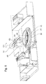
- FIG. 2 shows a machine tool having a machining head for outer teeth in accordance with an embodiment of the present disclosure.
- FIG. 3 shows a machine tool having a machining head for inner teeth in accordance with an embodiment of the present disclosure.
- FIG. 4 shows a machine tool having an inwardly pivoted portal in accordance with an embodiment of the present disclosure.
- FIG. 5 shows a machine tool having an inwardly pivoted portal and the second machining head in its work position in accordance with an embodiment of the present disclosure.
- FIG. 6 shows a machine tool having an inwardly pivoted portal and the second machining head in its work position in accordance with an embodiment of the present disclosure.
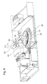
- FIG. 7 shows a section through a machine tool in accordance with an embodiment of the present disclosure.
- the figures are drawn approximately to scale and thus illustrate example relative dimensions and positioning with respect to each other, although other relative dimensions and positioning may be used, if desired.
- FIG. 1 shows a perspective view of a gear-cutting machine 1 for machining inner teeth in accordance with the prior art for machining large teeth.
- the gear-cutting machine in this respect has the degrees of freedom required for the machining and can in particular carry out the drawn movements A 1 , B 1 , C 1 , X 1 and Z 1 .
- X 1 describes the radial movement of the column carriage
- Z 1 the axial movement of the tool
- B 1 the rotary movement of the tool
- C 1 the rotary movement of the workpiece
- a 1 the pivot movement of the tool.
- Workpieces which are fastened to the machine table 30 can be machined at their inner diameters with the machining head shown for inner teeth 75 .
- the machining head for inner teeth 75 is moved by the machine column 10 to the machining site with the X 1 axle and dips during the machining by a linear movement of the Z 1 axle into the workpiece and in so doing generates the teeth, with the tool rotating about its B 1 axis for this purpose.
- This is controlled by an NC control with an operating unit 95 .
- the further machining heads 70 , 80 can be replaced as required with the machining head for inner teeth 75 if, e.g., outer teeth are to be machined.
- the machining head for outer teeth 70 is mounted instead of the machining head for inner teeth 75 .
- FIG. 2 a perspective representation of an embodiment of the machine in accordance with the present disclosure is shown.
- the machining head for outer teeth 70 is mounted at the machine column 10 .
- the portal carrier 50 with the second machining head 60 mounted thereat is located in an outwardly pivoted position. This position is reached in that the portal carrier is pivoted about the C 3 axis on the outer support column 45 .
- the support column 40 is here shown in the middle of the machine table 30 in its lowered position.
- the second machining head 60 in this embodiment has a vertical guide 65 via which a machining unit 85 can be supplied by the Z 5 axle in the direction toward the workpiece 25 and is there brought into engagement with the workpiece.
- the workpiece 25 is in this respect clamped on the apparatus 35 and on the machine table 30 .
- a change of the machining units 85 or of the tool for a machining unit can take place.
- the machining head 60 is for this purpose moved via the Y 1 axle along the portal carrier 50 for so long until an empty preparation space 90 is located beneath the machining head 60 .
- the machining unit 85 is lowered via the linear unit in the Z 5 axial direction and the no longer required machining unit 85 or the tool is placed down in this space in that the automatic interface is opened after reaching the placing down position.
- the linear unit 65 is again moved upwardly and the machining head 60 travels over the position with the new tool or the new machining unit.
- the linear unit 65 there travels downwardly until its automated interface travels onto the next tool or the next machining head.
- the interface closes and the linear unit 65 again travels back together with the tool or machining unit 85 into the working position by a Y 1 axial movement and an inward pivoting of the portal carrier about the C 3 axis.
- the working space is closed during the machining in that the two sliding doors 100 are moved together.
- FIG. 3 now shows a perspective representation of the machine in accordance with the present disclosure in which the middle support column is raised.
- the portal carrier can now be moved into its working position by pivoting the portal carrier about the C 3 axis.
- the front end of the carrier is coupled via coupler elements suitable for this purpose with the support column in the table middle 40 as is shown in FIG. 4 .
- the second machining head 60 can now be moved along the Y 1 axis in the direction toward the table middle into its working position. This situation is shown in FIG. 5 .
- the machining unit 85 is in this respect located in engagement with the workpiece 25 and machines its surface.
- FIG. 6 shows the machine in accordance with the present disclosure in an embodiment in which the two columns 40 , 45 were lowered together with the portal carrier to bring the tool into engagement.
- the outward projection of the linear unit is hereby considerably reduced. Higher cutting performances can hereby be processed or the quality of the machined surface is improved due to a lower sag of the linear unit.
- FIG. 7 A section through an embodiment of the machine in accordance with the present disclosure is shown in FIG. 7 .
- the support column 40 is shown in the middle of the machine table 30 in its lowered position.
- the column is supported in its support position 55 which allows a movement of the support column in the direction of the Z 4 axis.
- a workpiece 25 with the apparatus 35 is mounted on the machine table 30 .
- the machining head 70 is delivered with the column 10 along the X 1 axis on the column bed 20 in the direction toward the workpiece 25 .
- the carriage 15 serves to adjust the height of the machining head 70 in the Z 1 direction or to move the machining head 70 in the axial direction of the workpiece 25 , while the tool generates or machines the teeth.
Landscapes
- Engineering & Computer Science (AREA)
- Mechanical Engineering (AREA)
- Machine Tool Units (AREA)
- Gear Processing (AREA)
- Milling Processes (AREA)
Abstract
Description
Claims (9)
Applications Claiming Priority (3)
| Application Number | Priority Date | Filing Date | Title |
|---|---|---|---|
| DE102013013276.2 | 2013-08-08 | ||
| DE102013013276.2A DE102013013276A1 (en) | 2013-08-08 | 2013-08-08 | Machine tool and method for machining workpieces with at least two separate machining units |
| DE102013013276 | 2013-08-08 |
Publications (2)
| Publication Number | Publication Date |
|---|---|
| US20150043984A1 US20150043984A1 (en) | 2015-02-12 |
| US9463519B2 true US9463519B2 (en) | 2016-10-11 |
Family
ID=51178732
Family Applications (1)
| Application Number | Title | Priority Date | Filing Date |
|---|---|---|---|
| US14/448,546 Active 2034-09-03 US9463519B2 (en) | 2013-08-08 | 2014-07-31 | Machine tool and method for the machining of workpieces having at least two separate machining units |
Country Status (6)
| Country | Link |
|---|---|
| US (1) | US9463519B2 (en) |
| EP (1) | EP2835203B1 (en) |
| CN (1) | CN104339175B (en) |
| AU (1) | AU2014204532B2 (en) |
| DE (1) | DE102013013276A1 (en) |
| RU (1) | RU2596543C2 (en) |
Cited By (2)
| Publication number | Priority date | Publication date | Assignee | Title |
|---|---|---|---|---|
| US10197367B1 (en) * | 2016-05-19 | 2019-02-05 | Precision Machining Services, Inc. | Method of machining V-notch grooves for controlled fragmentation of warheads |
| US11179815B2 (en) | 2016-12-23 | 2021-11-23 | 9349-3039 Québec Inc. | Apparatus for reconditioning a heavy workpiece |
Families Citing this family (7)
| Publication number | Priority date | Publication date | Assignee | Title |
|---|---|---|---|---|
| CN104874867A (en) * | 2015-05-06 | 2015-09-02 | 宝鸡市新福泉机械科技发展有限责任公司 | High-precision and high-efficiency herringbone gear machine tool |
| DE102015219564A1 (en) * | 2015-10-09 | 2017-04-13 | Robert Bosch Gmbh | TOOL ANALYSIS DEVICE AND METHOD FOR ANALYZING A WORKING OF A WORKPIECE WITH A TOOL |
| CN108581075A (en) * | 2018-05-10 | 2018-09-28 | 重庆润跃机械有限公司 | Processing unit (plant) for gear |
| CN108747551B (en) * | 2018-09-05 | 2024-01-05 | 南通跃通数控设备股份有限公司 | Machining equipment |
| CN110293402B (en) * | 2019-07-04 | 2020-12-22 | 东北特钢集团山东鹰轮机械有限公司 | Multifunctional gear machining numerical control machine tool |
| GB2589874B (en) * | 2019-12-10 | 2024-05-01 | Fives Landis Ltd | Machine tools and methods of operation thereof |
| CN112475922B (en) * | 2020-12-14 | 2021-09-03 | 雄名航空科工(芜湖)股份有限公司 | Numerical control machine tool for three-body end-toothed disc production and processing |
Citations (20)
| Publication number | Priority date | Publication date | Assignee | Title |
|---|---|---|---|---|
| DE971083C (en) | 1953-02-23 | 1958-12-04 | Escher Wyss Gmbh | Carousel lathe |
| US2876650A (en) * | 1955-01-13 | 1959-03-10 | Sundstrand Machine Tool Co | Apparatus for automatically relatively positioning workholders, tools and the like |
| US3575086A (en) | 1969-07-03 | 1971-04-13 | Lockheed Aircraft Corp | Routing machine |
| JPS5828417A (en) | 1981-08-10 | 1983-02-19 | Hitachi Ltd | Compound gear working machine |
| US4589174A (en) * | 1984-03-27 | 1986-05-20 | Brigham Young University | Polar coordinate apparatus |
| US4658485A (en) * | 1984-08-21 | 1987-04-21 | Yang Tai Her | Machine tool with articulated crossbeam |
| US5081889A (en) * | 1988-02-17 | 1992-01-21 | Honda Giken Kogyo Kabushiki Kaisha | Workpiece machining system |
| DE19645324A1 (en) | 1996-11-04 | 1998-05-14 | Doerries Scharmann Gmbh | Machine tool for machining large components |
| US5779406A (en) * | 1996-07-17 | 1998-07-14 | Dresser Industries, Inc. | Forming a nonuniform groove in an annular bore wall |
| US5839323A (en) * | 1995-12-29 | 1998-11-24 | Helis S.A. | Moving gantry machine having uprights movable relative to each other |
| US5919012A (en) * | 1995-09-28 | 1999-07-06 | The Institute Of Physical And Chemical Research (Riken) | Method of high speed cutting mold and ultra-high speed milling machine |
| US6067695A (en) * | 1996-10-11 | 2000-05-30 | Noran S.L. | Double arm vertical miller |
| US20020107122A1 (en) * | 1998-12-28 | 2002-08-08 | Hoppe | Machine tool |
| US6865788B2 (en) * | 2001-08-21 | 2005-03-15 | O.M.V. Officine Meccaniche Venete S.R.L. | Numerical-control milling machine |
| US20060270540A1 (en) * | 2005-05-25 | 2006-11-30 | Mori Seiki Co., Ltd. | Machine Tool |
| US20070170140A1 (en) * | 2006-01-24 | 2007-07-26 | Asm Technology Singapore Pte Ltd | Gantry positioning system |
| DE202007012450U1 (en) | 2007-09-05 | 2007-11-08 | Schiess Gmbh | Vertical machining center in two-post version |
| DE102009008012A1 (en) | 2008-03-12 | 2009-10-15 | Honda Motor Co., Ltd. | motorcycle |
| US20090308214A1 (en) * | 2006-08-04 | 2009-12-17 | Citizen Holdings Co., Ltd. | Combined processing lathe and its tool post |
| WO2013037947A2 (en) | 2011-09-16 | 2013-03-21 | Mag Modul Verzahntechnik Gmbh | Machine tool for producing toothings on workpieces |
Family Cites Families (12)
| Publication number | Priority date | Publication date | Assignee | Title |
|---|---|---|---|---|
| CN2034486U (en) * | 1988-08-05 | 1989-03-22 | 耿建国 | Multifunctional drilling machine |
| CN2059863U (en) * | 1990-01-12 | 1990-08-01 | 江西省机床研究所 | Combined drill and mill machine with spindle box rotatable around column |
| CN2124793U (en) * | 1992-04-25 | 1992-12-16 | 黄明主 | Combined machine tool |
| DE102005034431A1 (en) * | 2005-07-14 | 2007-01-18 | Chiron-Werke Gmbh & Co. Kg | Machine tool with at least one machining unit and method for machining workpieces with such a machine tool |
| CN100411806C (en) * | 2006-03-02 | 2008-08-20 | 宜昌长机科技有限责任公司 | Numberical control milling-slotting combined machine tool and gear working method |
| CN200995308Y (en) * | 2007-01-24 | 2007-12-26 | 南京工业大学 | Numerical control milling and gear hobbing combined machine tool |
| CN201192786Y (en) * | 2008-04-29 | 2009-02-11 | 上海宝钢设备检修有限公司 | Cantilever rotary support |
| EP2161092B1 (en) * | 2008-09-04 | 2012-04-18 | GLEASON-PFAUTER, Maschinenfabrik GmbH | Gear grinder and method for dressing a grinding tool |
| CN201455626U (en) * | 2009-08-03 | 2010-05-12 | 张跃成 | Spring assembly pressing machine for coking oven door |
| RU98350U1 (en) * | 2009-10-14 | 2010-10-20 | ОАО "Стерлитамакский станкостроительный завод" ОАО "Стерлитамак-М.Т.Е." | MULTI-PURPOSE MACHINE WITH NUMERIC SOFTWARE CONTROL AND AUTOMATIC TOOL CHANGE |
| CN101700620B (en) * | 2009-11-11 | 2012-04-18 | 南京工业大学 | Large gantry polar coordinate CNC milling, hobbing and grinding compound machine tool |
| CN201990405U (en) * | 2011-04-15 | 2011-09-28 | 湖南骏昇机械制造有限公司 | Lifting device for top cover of cylinder body |
-
2013
- 2013-08-08 DE DE102013013276.2A patent/DE102013013276A1/en not_active Withdrawn
-
2014
- 2014-07-10 EP EP14176539.6A patent/EP2835203B1/en active Active
- 2014-07-21 AU AU2014204532A patent/AU2014204532B2/en not_active Ceased
- 2014-07-31 US US14/448,546 patent/US9463519B2/en active Active
- 2014-08-07 CN CN201410386921.6A patent/CN104339175B/en not_active Expired - Fee Related
- 2014-08-07 RU RU2014132702/02A patent/RU2596543C2/en not_active IP Right Cessation
Patent Citations (20)
| Publication number | Priority date | Publication date | Assignee | Title |
|---|---|---|---|---|
| DE971083C (en) | 1953-02-23 | 1958-12-04 | Escher Wyss Gmbh | Carousel lathe |
| US2876650A (en) * | 1955-01-13 | 1959-03-10 | Sundstrand Machine Tool Co | Apparatus for automatically relatively positioning workholders, tools and the like |
| US3575086A (en) | 1969-07-03 | 1971-04-13 | Lockheed Aircraft Corp | Routing machine |
| JPS5828417A (en) | 1981-08-10 | 1983-02-19 | Hitachi Ltd | Compound gear working machine |
| US4589174A (en) * | 1984-03-27 | 1986-05-20 | Brigham Young University | Polar coordinate apparatus |
| US4658485A (en) * | 1984-08-21 | 1987-04-21 | Yang Tai Her | Machine tool with articulated crossbeam |
| US5081889A (en) * | 1988-02-17 | 1992-01-21 | Honda Giken Kogyo Kabushiki Kaisha | Workpiece machining system |
| US5919012A (en) * | 1995-09-28 | 1999-07-06 | The Institute Of Physical And Chemical Research (Riken) | Method of high speed cutting mold and ultra-high speed milling machine |
| US5839323A (en) * | 1995-12-29 | 1998-11-24 | Helis S.A. | Moving gantry machine having uprights movable relative to each other |
| US5779406A (en) * | 1996-07-17 | 1998-07-14 | Dresser Industries, Inc. | Forming a nonuniform groove in an annular bore wall |
| US6067695A (en) * | 1996-10-11 | 2000-05-30 | Noran S.L. | Double arm vertical miller |
| DE19645324A1 (en) | 1996-11-04 | 1998-05-14 | Doerries Scharmann Gmbh | Machine tool for machining large components |
| US20020107122A1 (en) * | 1998-12-28 | 2002-08-08 | Hoppe | Machine tool |
| US6865788B2 (en) * | 2001-08-21 | 2005-03-15 | O.M.V. Officine Meccaniche Venete S.R.L. | Numerical-control milling machine |
| US20060270540A1 (en) * | 2005-05-25 | 2006-11-30 | Mori Seiki Co., Ltd. | Machine Tool |
| US20070170140A1 (en) * | 2006-01-24 | 2007-07-26 | Asm Technology Singapore Pte Ltd | Gantry positioning system |
| US20090308214A1 (en) * | 2006-08-04 | 2009-12-17 | Citizen Holdings Co., Ltd. | Combined processing lathe and its tool post |
| DE202007012450U1 (en) | 2007-09-05 | 2007-11-08 | Schiess Gmbh | Vertical machining center in two-post version |
| DE102009008012A1 (en) | 2008-03-12 | 2009-10-15 | Honda Motor Co., Ltd. | motorcycle |
| WO2013037947A2 (en) | 2011-09-16 | 2013-03-21 | Mag Modul Verzahntechnik Gmbh | Machine tool for producing toothings on workpieces |
Non-Patent Citations (1)
| Title |
|---|
| English Translation of DE 971083 C. * |
Cited By (2)
| Publication number | Priority date | Publication date | Assignee | Title |
|---|---|---|---|---|
| US10197367B1 (en) * | 2016-05-19 | 2019-02-05 | Precision Machining Services, Inc. | Method of machining V-notch grooves for controlled fragmentation of warheads |
| US11179815B2 (en) | 2016-12-23 | 2021-11-23 | 9349-3039 Québec Inc. | Apparatus for reconditioning a heavy workpiece |
Also Published As
| Publication number | Publication date |
|---|---|
| US20150043984A1 (en) | 2015-02-12 |
| RU2596543C2 (en) | 2016-09-10 |
| EP2835203A2 (en) | 2015-02-11 |
| DE102013013276A1 (en) | 2015-02-12 |
| AU2014204532A1 (en) | 2015-02-26 |
| RU2014132702A (en) | 2016-02-27 |
| CN104339175B (en) | 2018-01-02 |
| EP2835203A3 (en) | 2015-12-09 |
| EP2835203B1 (en) | 2019-12-04 |
| AU2014204532B2 (en) | 2017-01-12 |
| CN104339175A (en) | 2015-02-11 |
Similar Documents
| Publication | Publication Date | Title |
|---|---|---|
| US9463519B2 (en) | Machine tool and method for the machining of workpieces having at least two separate machining units | |
| DE10029967B4 (en) | Device for processing optical workpieces | |
| EP2255907B1 (en) | Machine tool and method for machining workpieces, in particular metal workpieces | |
| US7461441B2 (en) | Device and method for soft machining of bevel gears and use of the device | |
| EP2714309B1 (en) | Machine tool | |
| CN102161159A (en) | Vertical-horizontal combined machining centre | |
| EP2714308B1 (en) | Machine tool | |
| CN201970090U (en) | Vertical-horizontal combined machining center | |
| EP4316702B1 (en) | Numerically controlled multi-spindle lathe | |
| JP6807192B2 (en) | Machine Tools | |
| CN103084931A (en) | Double main shaft horizontal type combined processing center | |
| CN109318060A (en) | A kind of double main shaft double-workbench horizontal Machining centers of fixed column type | |
| US20130164090A1 (en) | Multi-Spindle Hobbing Machine | |
| CN114227500A (en) | PCB drill bit processing equipment | |
| CN101342614A (en) | Finger cutter type helical bevel gear processing device | |
| CN203019157U (en) | Horizontal composite processing center | |
| WO2019149761A1 (en) | Machine-tool | |
| CN109759935A (en) | A kind of five axis bull polishing machines | |
| CN110340412B (en) | Vertical and horizontal combined machining center | |
| CN102728900A (en) | Gear milling machine of fine-modulus spiral bevel gear | |
| KR101801202B1 (en) | Machining center with multiple spindle | |
| KR102144133B1 (en) | Universal head attachment for machine tool | |
| CN110039376B (en) | Six-axis double-tool magazine machining center | |
| KR20110067860A (en) | Straddle tool in vertical turning center | |
| CN210789966U (en) | Novel major axis turning lathe |
Legal Events
| Date | Code | Title | Description |
|---|---|---|---|
| AS | Assignment |
Owner name: LIEBHERR-VERZAHNTECHNIK GMBH, GERMANY Free format text: ASSIGNMENT OF ASSIGNORS INTEREST;ASSIGNOR:KELLER, THOMAS;REEL/FRAME:033438/0607 Effective date: 20140722 |
|
| AS | Assignment |
Owner name: LIEBHERR-VERZAHNTECHNIK GMBH, GERMANY Free format text: CORRECTIVE ASSIGNMENT TO CORRECT THE LAST NAME OF THE INVENTOR PREVIOUSLY RECORDED AT REEL: 033438 FRAME: 0607. ASSIGNOR(S) HEREBY CONFIRMS THE ASSIGNMENT;ASSIGNOR:ZELLER, THOMAS;REEL/FRAME:039417/0605 Effective date: 20140722 |
|
| STCF | Information on status: patent grant |
Free format text: PATENTED CASE |
|
| MAFP | Maintenance fee payment |
Free format text: PAYMENT OF MAINTENANCE FEE, 4TH YEAR, LARGE ENTITY (ORIGINAL EVENT CODE: M1551); ENTITY STATUS OF PATENT OWNER: LARGE ENTITY Year of fee payment: 4 |
|
| MAFP | Maintenance fee payment |
Free format text: PAYMENT OF MAINTENANCE FEE, 8TH YEAR, LARGE ENTITY (ORIGINAL EVENT CODE: M1552); ENTITY STATUS OF PATENT OWNER: LARGE ENTITY Year of fee payment: 8 |