US9446410B2 - Thermal cycler apparatus with elastomeric adhesive - Google Patents
Thermal cycler apparatus with elastomeric adhesive Download PDFInfo
- Publication number
- US9446410B2 US9446410B2 US13/989,344 US201113989344A US9446410B2 US 9446410 B2 US9446410 B2 US 9446410B2 US 201113989344 A US201113989344 A US 201113989344A US 9446410 B2 US9446410 B2 US 9446410B2
- Authority
- US
- United States
- Prior art keywords
- thermal cycler
- well
- cycler apparatus
- wells
- peltier device
- Prior art date
- Legal status (The legal status is an assumption and is not a legal conclusion. Google has not performed a legal analysis and makes no representation as to the accuracy of the status listed.)
- Active, expires
Links
Images


Classifications
-
- B—PERFORMING OPERATIONS; TRANSPORTING
- B01—PHYSICAL OR CHEMICAL PROCESSES OR APPARATUS IN GENERAL
- B01L—CHEMICAL OR PHYSICAL LABORATORY APPARATUS FOR GENERAL USE
- B01L7/00—Heating or cooling apparatus; Heat insulating devices
- B01L7/52—Heating or cooling apparatus; Heat insulating devices with provision for submitting samples to a predetermined sequence of different temperatures, e.g. for treating nucleic acid samples
-
- B—PERFORMING OPERATIONS; TRANSPORTING
- B01—PHYSICAL OR CHEMICAL PROCESSES OR APPARATUS IN GENERAL
- B01L—CHEMICAL OR PHYSICAL LABORATORY APPARATUS FOR GENERAL USE
- B01L2200/00—Solutions for specific problems relating to chemical or physical laboratory apparatus
- B01L2200/12—Specific details about manufacturing devices
-
- B—PERFORMING OPERATIONS; TRANSPORTING
- B01—PHYSICAL OR CHEMICAL PROCESSES OR APPARATUS IN GENERAL
- B01L—CHEMICAL OR PHYSICAL LABORATORY APPARATUS FOR GENERAL USE
- B01L2200/00—Solutions for specific problems relating to chemical or physical laboratory apparatus
- B01L2200/14—Process control and prevention of errors
- B01L2200/143—Quality control, feedback systems
- B01L2200/147—Employing temperature sensors
-
- B—PERFORMING OPERATIONS; TRANSPORTING
- B01—PHYSICAL OR CHEMICAL PROCESSES OR APPARATUS IN GENERAL
- B01L—CHEMICAL OR PHYSICAL LABORATORY APPARATUS FOR GENERAL USE
- B01L2300/00—Additional constructional details
- B01L2300/02—Identification, exchange or storage of information
- B01L2300/023—Sending and receiving of information, e.g. using Bluetooth®
-
- B—PERFORMING OPERATIONS; TRANSPORTING
- B01—PHYSICAL OR CHEMICAL PROCESSES OR APPARATUS IN GENERAL
- B01L—CHEMICAL OR PHYSICAL LABORATORY APPARATUS FOR GENERAL USE
- B01L2300/00—Additional constructional details
- B01L2300/02—Identification, exchange or storage of information
- B01L2300/024—Storing results with means integrated into the container
-
- B—PERFORMING OPERATIONS; TRANSPORTING
- B01—PHYSICAL OR CHEMICAL PROCESSES OR APPARATUS IN GENERAL
- B01L—CHEMICAL OR PHYSICAL LABORATORY APPARATUS FOR GENERAL USE
- B01L2300/00—Additional constructional details
- B01L2300/02—Identification, exchange or storage of information
- B01L2300/025—Displaying results or values with integrated means
- B01L2300/027—Digital display, e.g. LCD, LED
-
- B—PERFORMING OPERATIONS; TRANSPORTING
- B01—PHYSICAL OR CHEMICAL PROCESSES OR APPARATUS IN GENERAL
- B01L—CHEMICAL OR PHYSICAL LABORATORY APPARATUS FOR GENERAL USE
- B01L2300/00—Additional constructional details
- B01L2300/04—Closures and closing means
- B01L2300/046—Function or devices integrated in the closure
-
- B—PERFORMING OPERATIONS; TRANSPORTING
- B01—PHYSICAL OR CHEMICAL PROCESSES OR APPARATUS IN GENERAL
- B01L—CHEMICAL OR PHYSICAL LABORATORY APPARATUS FOR GENERAL USE
- B01L2300/00—Additional constructional details
- B01L2300/08—Geometry, shape and general structure
- B01L2300/0809—Geometry, shape and general structure rectangular shaped
- B01L2300/0829—Multi-well plates; Microtitration plates
-
- B—PERFORMING OPERATIONS; TRANSPORTING
- B01—PHYSICAL OR CHEMICAL PROCESSES OR APPARATUS IN GENERAL
- B01L—CHEMICAL OR PHYSICAL LABORATORY APPARATUS FOR GENERAL USE
- B01L2300/00—Additional constructional details
- B01L2300/08—Geometry, shape and general structure
- B01L2300/0832—Geometry, shape and general structure cylindrical, tube shaped
-
- B—PERFORMING OPERATIONS; TRANSPORTING
- B01—PHYSICAL OR CHEMICAL PROCESSES OR APPARATUS IN GENERAL
- B01L—CHEMICAL OR PHYSICAL LABORATORY APPARATUS FOR GENERAL USE
- B01L2300/00—Additional constructional details
- B01L2300/12—Specific details about materials
-
- B—PERFORMING OPERATIONS; TRANSPORTING
- B01—PHYSICAL OR CHEMICAL PROCESSES OR APPARATUS IN GENERAL
- B01L—CHEMICAL OR PHYSICAL LABORATORY APPARATUS FOR GENERAL USE
- B01L2300/00—Additional constructional details
- B01L2300/16—Surface properties and coatings
-
- B—PERFORMING OPERATIONS; TRANSPORTING
- B01—PHYSICAL OR CHEMICAL PROCESSES OR APPARATUS IN GENERAL
- B01L—CHEMICAL OR PHYSICAL LABORATORY APPARATUS FOR GENERAL USE
- B01L2300/00—Additional constructional details
- B01L2300/18—Means for temperature control
- B01L2300/1805—Conductive heating, heat from thermostatted solids is conducted to receptacles, e.g. heating plates, blocks
- B01L2300/1822—Conductive heating, heat from thermostatted solids is conducted to receptacles, e.g. heating plates, blocks using Peltier elements
-
- B—PERFORMING OPERATIONS; TRANSPORTING
- B01—PHYSICAL OR CHEMICAL PROCESSES OR APPARATUS IN GENERAL
- B01L—CHEMICAL OR PHYSICAL LABORATORY APPARATUS FOR GENERAL USE
- B01L2300/00—Additional constructional details
- B01L2300/18—Means for temperature control
- B01L2300/1894—Cooling means; Cryo cooling
-
- Y—GENERAL TAGGING OF NEW TECHNOLOGICAL DEVELOPMENTS; GENERAL TAGGING OF CROSS-SECTIONAL TECHNOLOGIES SPANNING OVER SEVERAL SECTIONS OF THE IPC; TECHNICAL SUBJECTS COVERED BY FORMER USPC CROSS-REFERENCE ART COLLECTIONS [XRACs] AND DIGESTS
- Y10—TECHNICAL SUBJECTS COVERED BY FORMER USPC
- Y10T—TECHNICAL SUBJECTS COVERED BY FORMER US CLASSIFICATION
- Y10T156/00—Adhesive bonding and miscellaneous chemical manufacture
- Y10T156/10—Methods of surface bonding and/or assembly therefor
- Y10T156/1052—Methods of surface bonding and/or assembly therefor with cutting, punching, tearing or severing
- Y10T156/1056—Perforating lamina
- Y10T156/1057—Subsequent to assembly of laminae
Definitions
- the present disclosure relates generally to an apparatus for thermal cycling. Certain embodiments relate more specifically to a method of manufacturing an apparatus and a method of using the apparatus.
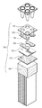
- FIG. 1 is a perspective view of a sample plate above a thermal cycler apparatus.
- FIG. 2 is a perspective view of the sample plate on a thermal cycler apparatus with a partial cut-away view.
- FIG. 3 is a cross-sectional view of the sample plate on the thermal cycler apparatus taken along cutting line 3 - 3 in FIG. 2 .
- FIG. 4 is an isolated sectional view taken along cutting line 4 - 4 in FIG. 2 of the thermal cycler apparatus.
- FIG. 5 is an exploded perspective of the sections shown in FIG. 4 of the sample plate on the thermal cycler apparatus.
- FIG. 6 is a cross-sectional side view taken along cutting line 6 - 6 in FIG. 4 of the embodiment of the thermal cycler apparatus and sample plate that are shown in FIGS. 1-5 .
- FIG. 7 is a cross-sectional side view of a different embodiment of thermal cycler apparatus.
- FIG. 8A is a cross-sectional side view of another embodiment of a thermal cycler apparatus.
- FIG. 8B is a perspective view of the embodiment of a thermal cycler apparatus shown in FIG. 8A with a cross-sectional view to show a clamp.
- FIG. 9 is a cross-sectional side view of an additional embodiment of a thermal cycler apparatus.
- FIG. 10 is a cross-sectional side view of another embodiment of a thermal cycler apparatus.
- FIG. 11 is a cross-sectional side view of yet another embodiment of a thermal cycler apparatus.
- FIG. 12 is a cross-sectional side view of the embodiment of the thermal cycler apparatus and sample plate shown in FIGS. 1-5 that shows the configuration of the thermal block plate.
- FIG. 13 is a perspective view of the well block shown in FIG. 1 .
- FIG. 14 is a cross-sectional side view of the well block taken along cutting line 14 - 14 in FIG. 13 .
- FIG. 15A is a perspective view of the well block and a base plate before they are joined together.
- FIG. 15B is a perspective view of the well block and a base plate after they are joined together.
- FIG. 15C is a perspective view, looking at the bottom of the wells, of the well block and paired sections of the base plate after removal of portions of the base plate.
- FIG. 16 is a perspective view, looking into the wells, of the well block and paired sections of the base plate after removal of portions of the base plate.
- FIG. 17 is a side cross-sectional view, of the well block and paired sections of the base plate after removal of portions of the base plate.
- FIG. 18 is a plan view of the paired section of the base plate on the well block as shown in FIGS. 15C-17 .
- FIG. 19 is a plan view of sections of the base plate that are on a plurality of wells of a well block.
- FIG. 20 is a perspective view of sections of the base plate that are on a plurality of wells of a well block.
- FIG. 21 is a perspective view, looking into the wells of the well block and sections of the base plate on a plurality of wells of the well block.
- FIG. 22 is a side cross-sectional view, of the well block and sections of the base plate on a plurality of wells of a well block.
- FIG. 23A is a perspective view of a peltier device receiving a temperature detector.
- FIG. 23B is a perspective view of a temperature detector on a peltier device.
- FIG. 24 is a perspective view of a peltier device on an adhesive on a heat sink.
- FIG. 25 is an exploded perspective view of peltier devices on a well block, adhesive, and base plates attached to a well block.
- FIG. 26 is a perspective view of a series of twenty-four peltier devices on a printed circuit and the wires that connect the devices with the printed circuit.
- FIG. 27 is a perspective view of a well block on the peltier devices shown in FIG. 26 and their associated wires.
- FIG. 28 is a block diagram of an automated system for nucleic acid amplification and analysis.
- FIG. 1 shows a sample plate 80 with sample wells 82 ready to be positioned on a well block 110 of a thermal cycler apparatus 100 such that each sample well 82 is positioned in a well 120 of well block 110 .
- FIG. 2 shows the same components after sample plate 80 is positioned on thermal block plate 110 .
- the configuration of thermal cycler apparatus 100 can be appreciated by studying FIGS. 3-6 .
- FIG. 3 is an enlarged view of the cut-away provided in FIG. 2 .
- FIGS. 4-6 provided isolated sectional views taken along cutting line 4 - 4 in FIG. 2 of the sample plate on the thermal block plate.
- FIGS. 3-6 show a sample 90 , illustratively for PCR, in each sample well 82 and the components of the embodiment of the thermal cycler apparatus shown at 100 including a well block 110 , a base plate 140 , a layer of adhesive 150 , a peltier device 160 , another layer of adhesive 170 and a heat sink 180 .
- well block 110 extends roughly half way up side wall 84 of sample well 82 .
- this is exemplary only and it is understood that other well block heights are within the scope of this invention, such as the tall well block 110 ′ shown in FIG. 7 .
- FIG. 5 provides the most insightful view as it can be seen that there is a pair of base plates 140 for each 4-well zone, and each pair spans between two adjacent wells. It can also be seen in FIG. 5 that the layer of adhesive 150 provides an interface with peltier device 160 . Additionally, it can be seen that peltier device 160 is thermally coupled to the pair of base plates 140 via the layer of adhesive 150 .
- FIG. 6 More detail regarding the plurality of wells 120 of well block 110 can be seen in FIG. 6 .
- Well 120 is shown having an upper conical sidewall 122 , a transitional sidewall 124 , a lower cylindrical sidewall 126 and a bottom 128 that is flat and extends between lower cylindrical sidewall 126 .
- Flat bottom 128 rests on base plate 140 , which rests on adhesive 150 to be thermally coupled to peltier plate 160 .
- FIG. 6 also shows more details about the configuration of sample well 82 including sidewall 84 , rounded bottom-section 86 of well 82 and the round apex 88 .
- the layers of adhesive 150 and 170 may be the same material.
- the adhesive is ductile and flexible, has relatively high thermal conductivity and low viscosity.
- the adhesive enhances the uniformity of heat transfer between peltier 160 and wells 120 .
- the adhesive permits apparatus 100 to be assembled without the use of conventional clamps used to clamp a well block to a heat sink.
- the adhesive is capable of retaining the peltier device 160 adjacent to the structure contacted by the adhesive such as the wells 120 of well block 110 and/or heat sink 180 even when apparatus 100 is turned upside down without clamping well block 110 to heat sink 180 .
- a suitable adhesive are capable of cycling between a temperature at least as high as 95° C. and at least as low as 60° C. at least about 5,000 times, at least about 10,000 times, at least about 100,000 times, or at least about 200,000 times and still be capable of retaining peltier device 160 .
- Various embodiments of a suitable adhesive may have an elongation, as defined below in the Examples, of at least about 15%, 20%, 22%, 35%, 40%, 50%, 55%, 60%, 70%, 90%, 110%, 120%, 180%, 200%, 400% or ranges within combinations of these values such as about 15% to about 1,000%, about 35% to about 700%, about 70% to about 500%, or between 100% to about 200%.
- Suitable adhesives may also have an unprimed adhesion lap shear of between about 1 kgf/cm 2 and about 75 kgf/cm 2 , over about 10 kgf/cm 2 , between about 10 kgf/cm 2 and about 45 kgf/cm 2 .
- the viscosity of the adhesive may range between about 1,000 centipoise and about 200,000 centipoise, between about 10,000 centipoise and about 150,000 centipoise, between about 20,000 centipoise and about 80,000 centipoise, or between about 30,000 centipoise and about 40,000 centipoise.
- Various embodiments may also have a thermal conductivity, as defined below in the Examples, of at least about 0.39, 0.40, 0.74, 0.77, 0.84, 0.85, 0.9, 0.92, 0.95, 1.1, 1.4, 1.53, 1.8, 1.9, 1.97, 2.2, 2.5 or ranges within combinations of these values such as about 0.74 to about 2.5 or about 0.9 to about 1.8.
- the adhesive has a thermal conductivity at 25° C./77° F. of between about 0.7 Watt/meter-K and about 2.5 Watt/meter-K.
- the adhesive has a thermal conductivity at 25° C./77° F. of between about 0.8 Watt/meter-K and about 2.0 Watt/meter-K.
- the adhesive has a thermal conductivity at 25° C./77° F. of between about 0.9 Watt/meter-K and about 1.5 Watt/meter-K. In yet another embodiment, the adhesive has a thermal conductivity at 25° C./77° F. of over about 1.0 Watt/meter-K. In a further embodiment, the polymer has a thermal conductivity at 25° C./77° F. of about 1.1 Watt/meter-K.
- suitable adhesives include thermally conductive silicone pastes, which are non-curing.
- suitable thermally conductive silicone pastes which are non-curing.
- Specific trade names of suitable thermally conductive silicone pastes, which are non-curing, are provided by those listed in the Examples.
- apparatus 100 ′ differs from apparatus 100 as apparatus 100 ′ does not have base plates such as base plate 140 .
- apparatus 100 ′ features a well block 110 ′ having wells 120 ′ with taller side walls 122 ′.
- the embodiments of the well blocks disclosed herein may each have such taller side walls instead of side walls 122 or side walls 422 .
- Wells 120 ′ have flat bottoms 128 that are directly over and in contact with a layer of adhesive 150 .
- apparatus 100 ′ provides less area for layer of adhesive 150 to bond to relative to the configuration of apparatus 100
- the configuration of apparatus 100 ′ also permits faster heat transfer between peltier device 160 and wells 120 ′ as there is less mass for the heat to pass through without a base plate.
- FIGS. 8A-8B depicts another embodiment of a thermal cycler apparatus at 200 .
- Apparatus 200 features a carbon sheet or grease or other non-binding thermal interface material at 270 instead of an adhesive.
- the non-binding thermal interface material 270 may also replace the layer of adhesive 150 .
- Clamp bar 230 may alternatively rest on a thin compression pad or compliant layer 232 that may be formed from a suitable material such as silicone.
- Clamp bar 230 extends across adjacent base plates 140 and can be attached at its ends with conventional mechanisms for clamp systems to the apparatus 200 . It is also possible use clamp screws that extend through the well block and into the heat sink.
- Various clamp bar and clamp screw embodiments are known in the art.
- FIG. 9 depicts another embodiment of a thermal cycler apparatus at 300 .
- Apparatus 300 features solder 370 between peltier device 160 and heat sink 180 . As with the embodiments shown in FIGS. 6-7 , with this configuration, it is also not necessary for well block 110 to be clamped to heat sink 180 .
- FIG. 10 depicts another embodiment of a thermal cycler apparatus at 400 .
- Apparatus 400 features a well block 410 with wells 420 that have sidewalls 422 , which transition to rounded bottoms 426 and have a rounded apex 428 instead of a flat bottom. Also, the rounded bottom of each well 420 rests in solder 440 illustratively with rounded apex 428 directly contacting peltier device 160 . Wells with flat bottoms such as wells 120 can also be soldered like wells 420 directly to a peltier device, as shown in FIG. 7 .
- FIG. 11 depicts another embodiment of a thermal cycler apparatus at 500 .
- Apparatus 500 features well block 110 , on base plate 240 , which is soldered to peltier device 160 via solder 350 .
- Peltier device 160 rests on non-binding thermal interface material 270 so clamp bar 230 is also used with the same configuration as described above with respect to apparatus 200 .
- apparatus 500 can be modified by replacing solder 350 with adhesive 150 or with non-binding thermal interface material 270 such as carbon or grease.
- FIG. 12 corresponds with the embodiment shown in FIGS. 1-6 and shows all of the components of a single zone.
- Apparatus 100 has a well block 110 that comprises a plurality of 4-well zones, wherein each 4-well zone comprises a first pair of wells 120 and a second pair of wells 120 , and wherein each first pair of wells 120 and each second pair of wells 120 are respectively over a first base plate and a second base plate such that one peltier device 160 provides for heat transfer for one 4-well zone.
- Each peltier device 160 heats or cools a pair of base plates 140 via adhesive 150 to heat or cool the sample in the four sample wells via each bottom 128 and side walls 122 of the four wells 120 .
- Heat sink 180 is thermally connected to peltier device 160 via adhesive 170 . It is understood that the 4-well zone is illustrative only, and that each zone may comprise various other numbers of wells.
- FIG. 14 provides references for describing the dimensions of well 120 .
- the length of lower cylindrical sidewall 126 is identified as L 1
- the diameter of flat bottom 128 is identified as L 2
- the depth of well 120 is identified as L 3
- the angle between the upper conical sidewall 122 and a line extending from the lower cylindrical sidewall 126 is identified as ⁇ 1 .
- the angle, ⁇ 1 between the upper conical sidewall 122 and the lower cylindrical sidewall 126 in one embodiment is about 16°, such as 16.3°, however other angles are within the scope of this invention and may approximately correspond to external dimensions of commercially available microtiter plates.
- the angle, ⁇ 2 between the lower cylindrical sidewall 126 and flat bottom 128 is equal to or slightly greater than 90°, such as 92°, however other angles are within the scope of this invention. While a 90° angle ⁇ 2 is contemplated, angles slightly greater than 90° may be desired, illustratively to ease removal of well block 110 from the mold used in the manufacturing process. It is understood that if angles slightly greater than 90° for ⁇ 2 are used, that cylindrical sidewall 126 will define a generally cylindrical section that is, in fact, slightly conical. Illustratively, ⁇ 2 is less than 90°+ ⁇ 1 , illustratively 95° degrees or less, and more illustratively, 92° or less.
- flat bottom 128 An advantage of flat bottom 128 relative to prior art configurations is that the shape can be manufactured with greater uniformity, and provides additional surface area that enables heat to be transferred with greater uniformity and at a more rapid rate.
- flat bottom 128 may have rounded edges near sidewall 126 or otherwise may not be completely flat from one side of cylindrical sidewall 126 to the other.
- lower cylindrical sidewall 126 does not interfere with insertion of the sample well 82 into well 120 , the shape of the well 120 allows sample well 82 to have maximal contact with the sidewall 122 of the wells in each well block.
- An average well 120 ′ of well block 110 ′ is close to the height of sample well 82 and illustratively has a depth of about 0.5 inches-0.6 inches for a 96-well plate.
- Such a well block allows sample well 82 to be filled with a large sample volume and also mitigates against the effects of a heated lid that may be at a static temperature.
- Most embodiments illustrated in this disclosure, including in FIGS. 1-6, 8-17, 20-22, and 25 have a depth of well 120 , L 3 , that is shorter, illustratively only about 0.3 inches for a 96-well plate.
- An advantage of this configuration is a decrease in the incidence of sidewall condensation, particularly during cooling.
- FIGS. 15A-15C depict an illustrative method of manufacturing a well block assembly 149 to yield pairs of base plates on the bottoms of wells.
- First a precursor base plate sheet 142 is obtained as shown in FIG. 15A and then is attached to flat bottom 128 illustratively by soldering, as illustrated in FIG. 15B . Then, portions of the precursor base plate sheet are removed to yield pairs of base plates 144 a , 144 b that span adjacent wells, as shown in FIG. 15C .
- the portions of the base plate sheet may be removed by any conventional method such as machining, punching, stamping, or dicing. Alternatively, the base sheet could be cut first and the base plates added thereto.
- channels 141 are formed that may be used as space for wiring, illustratively to wire the peltiers 160 or temperature detectors 167 , as shown in FIGS. 26-27 .
- FIG. 16 shows another view of well block 110 with paired sections of the base plate.
- FIG. 17 provides the identification of the length of base plate 140 , which is L 4 .
- FIGS. 18 and 19 provide the same view of different embodiments.
- FIG. 18 corresponds with apparatus 100 .
- FIG. 19 shows base plates 240 that connects more than four wells. Such an embodiment may result in increased uniformity, albeit with a reduction in control.
- Base plates 240 are also more easily used with a clamp bar such as clamp bar 230 shown in FIGS. 8A-8B and FIG. 11 .
- a solid base plate may be acceptable in some embodiments, illustratively with recessed temperature sensors.
- FIGS. 20-22 show the same embodiment depicted in FIG. 19 but from a different views.
- FIG. 22 provides the identification of the length of base plate 140 ′, which is L 5 when it spans wells that are at the perimeter and is L 6 when it spans wells not at the perimeter.
- FIGS. 23A-23B provide more detailed views of peltier device 160 .
- heat directing element 163 is connected to printed circuit 166 , which is connected, illustratively by solder or adhesive, to a temperature detector 167 , illustratively a resistance temperature detector.
- FIGS. 24-25 depict a method of manufacturing apparatus 100 .
- FIG. 24 shows peltier device 160 being placed on adhesive 170 .
- FIG. 25 shows the subsequent steps of placing adhesive 150 on peltiers 160 followed by placement of base plates 140 on adhesive 150 .
- An advantage of this configuration is that clamps or screws such as those described above are not necessary. However, use of such clamps or screws is not precluded with apparatus 100 .
- peltiers 160 are used, although it is understood that more or fewer peltiers 160 may be used, depending on the desired application.
- a 96-well plate between 4 and 96 peltiers may be used, with zones of 24 wells if 4 peltiers are used, down to zones of one well, with each peltier controlling an individual well.
- each peltier device 160 is individually driven.
- the peltiers 160 are not in series nor parallel.
- Such may be used to provide greater well-to-well uniformity, for example by heating the exterior peltiers to a slightly higher temperature, thus reducing the issue of cooler maximum temperatures in the exterior wells, particularly in the corner wells.
- Individually driven peltiers 160 also may be used to provide for a temperature gradient across the plate.
- FIG. 26 is a perspective view of a series of twenty-four peltier devices 160 on heat sink 180 and their wires that connect peltier devices 160 to a printed circuit.
- the printed circuit is connected to the temperature detectors 167 .
- FIG. 27 shows well block 110 on peltier devices shown in FIG. 26 and their associated wires 181 .
- a channel 141 which is a space, between each pair of base plates 140 , so when well block 110 and base plates 140 are placed on peltier devices 160 , the wires extending from peltier devices 160 may extend through this space.
- FIG. 28 shows an automated system containing thermal cycler apparatus 100 .
- Thermal cycler apparatus 100 is mounted within a housing 101 .
- Well block 110 is positioned to receive sample plate 80 once sample plate 80 is inserted into opening 102 .
- Opening 102 is a movable lid, but it is understood that opening 102 can be any type of opening as are known in the art, including a slot, a door, etc.
- the lid mechanism may close down onto sample plate 80 to seal the sample within sample wells 82 or to force wells 82 of sample plate 80 into better contact with wells 120 of well block 110 .
- an optics block 109 may be provided for sample excitation and detection.
- Optics block 109 may provide single-color or multi-color detection, as is known in the art.
- the system includes a computing device 104 , which may comprise one or more processors, memories, computer-readable media, one or more HMI devices 103 (e.g., input-output devices, displays, printers, and the like), one or more communications interfaces (e.g., network interfaces, Universal Serial Bus (USB) interfaces, etc.), and the like.
- Computing device 104 may be provided within housing 101 , or may be provided separately, such as a laptop or desktop computer, or portions of computing device 104 may be resident within housing 101 , while other portions are located separately and may be coupled through wiring or wirelessly.
- Computing device 104 may be configured to load computer-readable program code for controlling thermal cycler apparatus 100 and optics block 109 .
- thermal cycler apparatus 100 in housing 101 may be provided in an automated system with a robotics unit 105 .
- the robotics unit 105 may be programmed to load the samples into sample wells 82 and then load sample plate 80 into housing 101 through opening 102 .
- robotics unit 105 may also prepare the samples prior to loading into sample wells 82 .
- Teach points may be used by robotics unit 105 for orienting plate 80 into well block 110 . Teach points 134 a - c are best seen in FIG. 16 , where three teach points are used.
- teach point 134 a is located near a first edge 177
- teach points 134 b and 134 c are located near a second edge 178 of well block 110 .
- the robotics unit 105 can easily identify the orientation of well block 110 .
- three teach points is illustrative and any number of teach points can be used.
- Control of robotics unit 105 may be through computing device 104 , or robotics unit 105 may be controlled by a separate processor.
- robotics unit 105 may be configured to load samples into multiple thermal cycler devices.
- the apparatus may be the following, although similar equipment may be used provided it is capable of the accuracy and precision required.
- the dies used may be the ASTM D412 die C or others as specified, from any suitable source.
- the marker used may be a bench marker with two parallel lines 1+/ ⁇ 0.003 in. (2.54+/ ⁇ 0.0076 cm) apart for dies C and D and 2+/ ⁇ 0.003 in. (5.08/+/ ⁇ 0.0076 cm) for A, B, E and F, from any suitable source of commercial rubber stamp pads.
- the micrometer used should be capable to +/ ⁇ 0.001 in.
- the molds used may be aluminum and may prepare samples at least 4 in. ⁇ 4 in. (10.2 cm ⁇ 10.2 cm) and between 0.06 in and 0.12 in. (0.15 cm and 0.30 cm) thick, as specified, from any suitable source.
- the press may be any small hand operated press suitable for cutting the test bars. Examples of such presses include tensile testers from Monsanto Instruments, Akron, Ohio; Instron Corp., Canton, Mass.; or United Testing Systems, Auburn Heights, Mich.
- a standard test slab (0.080+/ ⁇ 0.008 inches thick, 2.0+/ ⁇ 0.2 mm) of the material to be tested was molded and cured as specified. The slab was allowed to rest at room temperature on a flat surface for at least 3 h. The room in which the testing was performed was maintained at 23+/ ⁇ 2° C. Using the ASTM D412 Disc or other specified die and a press, three bars (or the specified number of test bars) were cut parallel with the grain, if any, of the material.
- A W/[(D) (L)] where A is the area in cm 2 ; W is the weight in air in g; D is the density in g/cm 3 ; and L is the length in cm.
- pieces of tubing too small to cut suitable bars from may be pulled, if the area is calculated. For tubing with OD 3 ⁇ 8 in. (0.95 cm) or less, this may be approximated.
- A (CSA, 1 ) ⁇ (CSA, 2 ); where CSA, 1 is the area using outside diameter and CSA, 2 is the area using inside diameter.
- each test bar was marked with a 1 in. (2.54 cm), “L,o” bench mark that was equidistant from the center line of the reduced section and perpendicular to its longitudinal axis. It is noted that whenever samples were heat aged or stored prior to testing, they are marked for identification by notching the ends rather than with an ink mark if there is the possibility of the ink affecting the samples.
- test bar was placed in the grips of the tester and adjusted so the tension was uniformly distributed over the cross section of the bar during the test.
- the machine was started, the bar was stretched to the breaking point and the necessary data to complete the calculations as specified was recorded.
- instrument may be equipped with a mechanical or electrical measuring system and may have a manual or automatic recording system.
- the calculations may be performed by a computer attached to the test instrument.
- the rupture points of the bars should be observed as an indication of problem with the dies. Thus, if all samples break in the same area, a die problem may exist. If this occurred, the test was repeated with the remaining test bars. The required result was calculated and the median values were reported unless another reporting mode is specified. If specified, other reporting modes or values may be reported, e.g. average, weighted average, lowest value, highest value.
- the tensile tester, bench marker, and micrometer were on a routine calibration schedule.
- Elongation is the extension of a test bar to rupture expressed as a percentage of the original length and measured by the bench marks. It is also known as ultimate elongation or elongation at break. The term may also be used to describe a specific percentage extension when used with modulus or tension set (i.e. modulus at 200% elongation).
- Elongation, 5 is calculated as [ ⁇ (L, 1 ) ⁇ (L,o) ⁇ (100)]/(L,o) where L, 1 is the length at break between bench marks and I,o is the original length between bench marks. With an elongation gage and a 1 in. (2.54 cm) bench mark spacing, the percentage elongation may be read directly as E, %.
- Tensile stress is the applied force per unit of original cross sectional area of a test bar.
- Tension set after break is the set (extension) remaining after a test bar has been stretched to rupture and allowed to retract for 10 min, expressed as a percentage of the original length of the bench mark. This is not to be confused with tension set.
- Tension set is the set (extension) remaining after a test bar has been stretched to a given percentage elongation and allowed to retract, expressed as a percentage of the original length of the bench mark.
- the value is obtained as follows: the bar is placed in the grips. The grips are spread at 20 in./min (50.8+/ ⁇ 2.5 cm/min) to the specified percentage elongation. The machine is secured and the sample is allowed to remain under tension for a specified time. The sample is released quickly but without snap and the bar is removed. The bar is allowed to rest flat for a specified time and the distance between the bench marks to 1% of the original length is measured. Calculate as for tension set after break. The result is generally reported with the percentage elongation, such as “tension set, 200 .”
- the precision of the various results should be within +/ ⁇ 15% to ensure repeatability, reproducibility, and accuracy.
- thermally conductive compounds listed in Table 1, below, are available from DOW CORNING, and were all tested using the exemplary method described previously. Relevant data is shown.
- the compound AS 1808 available from ACC SILICONES (Somerset, UK), was tested using a method comparable to the exemplary method described previously. Its thermal conductivity at 25° C./77° F. (Watt/meter-K), Elongation (%), and Overlap Shear Strength Aluminum (kg/cm2) are 1.79, 91, and 12.31, respectively.
- PCR strand displacement amplification
- NASBA nucleic acid sequence-based amplification
- CRCA cascade rolling circle amplification
- ICAN isothermal and chimeric primer-initiated amplification of nucleic acids
- TMA transcription-mediated amplification
- Asymmetric PCR may also be used. Therefore, when the term PCR is used herein, it should be understood to include variations on PCR as well as other alternative amplification methods, as well as post-PCR processing, such as melt curve analysis.
- melt curve analysis can be found in U.S. Pat. No. 7,387,887, which is incorporated herein by reference.
- the devices of this disclosure may be suitable for a variety of other biological and non-biological reactions that require temperature control.
- Any methods disclosed herein comprise one or more steps or actions for performing the described method.
- the method steps and/or actions may be interchanged with one another.
- the order and/or use of specific steps and/or actions may be modified.
- any reference to “one embodiment,” “an embodiment,” or “the embodiment” means that a particular feature, structure, or characteristic described in connection with that embodiment is included in at least one embodiment.
- the quoted phrases, or variations thereof, as recited throughout this specification are not necessarily all referring to the same embodiment.
Landscapes
- Health & Medical Sciences (AREA)
- Chemical & Material Sciences (AREA)
- Life Sciences & Earth Sciences (AREA)
- Biochemistry (AREA)
- General Health & Medical Sciences (AREA)
- Molecular Biology (AREA)
- Clinical Laboratory Science (AREA)
- Chemical Kinetics & Catalysis (AREA)
- Apparatus Associated With Microorganisms And Enzymes (AREA)
- Devices For Use In Laboratory Experiments (AREA)
- Measuring Or Testing Involving Enzymes Or Micro-Organisms (AREA)
- Sampling And Sample Adjustment (AREA)
Priority Applications (1)
| Application Number | Priority Date | Filing Date | Title |
|---|---|---|---|
| US13/989,344 US9446410B2 (en) | 2010-12-03 | 2011-12-02 | Thermal cycler apparatus with elastomeric adhesive |
Applications Claiming Priority (3)
| Application Number | Priority Date | Filing Date | Title |
|---|---|---|---|
| US41968010P | 2010-12-03 | 2010-12-03 | |
| US13/989,344 US9446410B2 (en) | 2010-12-03 | 2011-12-02 | Thermal cycler apparatus with elastomeric adhesive |
| PCT/US2011/063005 WO2012075360A1 (en) | 2010-12-03 | 2011-12-02 | Thermal cycler apparatus and related methods |
Related Parent Applications (1)
| Application Number | Title | Priority Date | Filing Date |
|---|---|---|---|
| PCT/US2011/063005 A-371-Of-International WO2012075360A1 (en) | 2010-12-03 | 2011-12-02 | Thermal cycler apparatus and related methods |
Related Child Applications (1)
| Application Number | Title | Priority Date | Filing Date |
|---|---|---|---|
| US15/229,046 Division US11376599B2 (en) | 2010-12-03 | 2016-08-04 | Thermal cycler apparatus and related methods |
Publications (2)
| Publication Number | Publication Date |
|---|---|
| US20140051155A1 US20140051155A1 (en) | 2014-02-20 |
| US9446410B2 true US9446410B2 (en) | 2016-09-20 |
Family
ID=46172282
Family Applications (2)
| Application Number | Title | Priority Date | Filing Date |
|---|---|---|---|
| US13/989,344 Active 2032-06-13 US9446410B2 (en) | 2010-12-03 | 2011-12-02 | Thermal cycler apparatus with elastomeric adhesive |
| US15/229,046 Active 2033-03-11 US11376599B2 (en) | 2010-12-03 | 2016-08-04 | Thermal cycler apparatus and related methods |
Family Applications After (1)
| Application Number | Title | Priority Date | Filing Date |
|---|---|---|---|
| US15/229,046 Active 2033-03-11 US11376599B2 (en) | 2010-12-03 | 2016-08-04 | Thermal cycler apparatus and related methods |
Country Status (7)
| Country | Link |
|---|---|
| US (2) | US9446410B2 (de) |
| EP (1) | EP2646542B1 (de) |
| JP (2) | JP5934241B2 (de) |
| CN (1) | CN103347994A (de) |
| CA (1) | CA2819254C (de) |
| SG (2) | SG190979A1 (de) |
| WO (1) | WO2012075360A1 (de) |
Cited By (2)
| Publication number | Priority date | Publication date | Assignee | Title |
|---|---|---|---|---|
| US20200041405A1 (en) * | 2017-01-19 | 2020-02-06 | Agilent Technologies, Inc. | Multi-temperature optical spectrometer modules, systems and methods of using the same |
| US12077813B2 (en) | 2021-09-23 | 2024-09-03 | N6 Tec, Inc. | Methods and systems for sample analysis |
Families Citing this family (23)
| Publication number | Priority date | Publication date | Assignee | Title |
|---|---|---|---|---|
| EP2646542B1 (de) | 2010-12-03 | 2023-10-18 | BioFire Defense, LLC | Thermocycler-vorrichtung |
| AU2013202793B2 (en) * | 2012-07-31 | 2014-09-18 | Gen-Probe Incorporated | System, method and apparatus for automated incubation |
| US20140273181A1 (en) | 2013-03-15 | 2014-09-18 | Biofire Diagnostics, Inc. | Compact optical system for substantially simultaneous monitoring of samples in a sample array |
| USD749713S1 (en) * | 2014-07-31 | 2016-02-16 | Innovative Medical Equipment, Llc | Heat exchanger |
| US10613031B2 (en) | 2015-12-18 | 2020-04-07 | Biofire Defense, Llc | Solid fluorescence standard |
| EP3747546B1 (de) * | 2016-09-01 | 2022-04-13 | Roche Diagnostics GmbH | Anordnung, instrument zur durchführung einer temperaturabhängigen reaktion und verfahren zur durchführung einer temperaturabhängigen reaktion in einer anordnung |
| TWI698879B (zh) * | 2017-06-09 | 2020-07-11 | 英業達股份有限公司 | 自動燒錄系統 |
| CN108531390A (zh) * | 2018-04-11 | 2018-09-14 | 张薇 | 一种便携式可用于现场检测核酸的设备 |
| KR102022198B1 (ko) * | 2018-09-17 | 2019-09-18 | 서강대학교산학협력단 | 플라즈몬 가열 및 온도 산출 시스템 및 그 방법 |
| US11474055B2 (en) * | 2018-10-22 | 2022-10-18 | Waters Technologies Corporation | High sample throughput differential scanning calorimeter |
| KR101946217B1 (ko) | 2018-11-30 | 2019-02-08 | 김학진 | 진온플레이트 |
| KR102651375B1 (ko) * | 2019-03-18 | 2024-03-26 | 주식회사 씨젠 | 샘플 홀더 어셈블리를 포함하는 써멀 사이클러 |
| EP3831490A1 (de) * | 2019-12-03 | 2021-06-09 | Eppendorf AG | Thermoblock zur aufnahme und temperierung mindestens eines laborprobengefässes, herstellungsverfahren und simulationsverfahren |
| CN112827524A (zh) * | 2020-08-10 | 2021-05-25 | 深圳市瑞沃德生命科技有限公司 | 一种热循环装置 |
| KR102578721B1 (ko) * | 2020-10-05 | 2023-09-15 | (주)바이오니아 | 핵산증폭검사장치 및 이를 구비하는 시료자동분석시스템 |
| DE102021126130A1 (de) | 2021-10-08 | 2023-04-13 | Bayerische Motoren Werke Aktiengesellschaft | System mit einer steuerbaren Kühleinrichtung und Kraftfahrzeug |
| FR3130646A1 (fr) * | 2021-11-15 | 2023-06-23 | Biomerieux | Système de préparation automatisée d’un échantillon biologique |
| CN115074236B (zh) * | 2022-07-21 | 2022-10-25 | 鲲鹏基因(北京)科技有限责任公司 | 用于pcr仪的温控装置、扩增设备和pcr仪 |
| WO2024107618A1 (en) * | 2022-11-16 | 2024-05-23 | 10X Genomics, Inc. | Systems and methods for thermal management of reagent well plates |
| EP4695027A1 (de) * | 2023-04-14 | 2026-02-18 | Foundation Medicine, Inc. | Verfahren und systeme zur erzielung temperaturgesteuerter reaktionsbedingungen in mikroplattenbehältern mit grossem volumen |
| US20240382970A1 (en) * | 2023-05-19 | 2024-11-21 | Opentrons LabWorks Inc. | Apparatus for controlled release of a thermocycler seal |
| WO2025127693A1 (en) * | 2023-12-13 | 2025-06-19 | Seegene, Inc. | Thermal cycler |
| WO2025143897A1 (ko) * | 2023-12-28 | 2025-07-03 | 주식회사 씨젠 | 중간부 슬릿이 형성된 방열판을 포함하는 써멀 모듈 |
Citations (17)
| Publication number | Priority date | Publication date | Assignee | Title |
|---|---|---|---|---|
| US6197572B1 (en) | 1998-05-04 | 2001-03-06 | Roche Diagnostics Corporation | Thermal cycler having an automatically positionable lid |
| JP2001241761A (ja) | 2000-02-28 | 2001-09-07 | Noritz Corp | 流体加熱機器の加熱制御方法 |
| US6337435B1 (en) | 1999-07-30 | 2002-01-08 | Bio-Rad Laboratories, Inc. | Temperature control for multi-vessel reaction apparatus |
| JP2002010775A (ja) | 2000-04-27 | 2002-01-15 | Hitachi Electronics Eng Co Ltd | Dnaサンプル作成用反応装置 |
| US20030008308A1 (en) * | 2001-04-06 | 2003-01-09 | California Institute Of Technology | Nucleic acid amplification utilizing microfluidic devices |
| US20060094108A1 (en) | 2002-12-20 | 2006-05-04 | Karl Yoder | Thermal cycler for microfluidic array assays |
| JP2006224060A (ja) | 2005-02-21 | 2006-08-31 | Yamaha Corp | マイクロチップ用の温度制御装置 |
| US20060286659A1 (en) | 1990-11-29 | 2006-12-21 | Applera Corporation | Thermal cycler for automatic performance of the polymerase chain reaction with close temperature control |
| WO2008030914A2 (en) | 2006-09-06 | 2008-03-13 | Applera Corporation | Device for carrying out chemical or biological reactions |
| CN101194021A (zh) | 2005-05-13 | 2008-06-04 | 阿普里拉股份有限公司 | 低质量的热循环均温块 |
| WO2008070198A2 (en) | 2006-05-17 | 2008-06-12 | California Institute Of Technology | Thermal cycling system |
| US7387887B2 (en) | 2004-04-20 | 2008-06-17 | University Of Utah Research Foundation | Nucleic acid melting analysis with saturation dyes |
| US20090130719A1 (en) * | 2007-07-13 | 2009-05-21 | Handylab, Inc. | Microfluidic Cartridge |
| US20090263782A1 (en) | 2006-09-19 | 2009-10-22 | David Ward | Reaction apparatus |
| JP2009278971A (ja) | 2008-05-19 | 2009-12-03 | F Hoffmann La Roche Ag | 改良された冷却器/加熱器の構成 |
| US20100081191A1 (en) | 2008-09-26 | 2010-04-01 | Marlow Industries, Inc. | Anisotropic heat spreader for use with a thermoelectric device |
| WO2012075360A1 (en) | 2010-12-03 | 2012-06-07 | Idaho Technology, Inc. | Thermal cycler apparatus and related methods |
Family Cites Families (12)
| Publication number | Priority date | Publication date | Assignee | Title |
|---|---|---|---|---|
| AU736484B2 (en) * | 1997-03-28 | 2001-07-26 | Applied Biosystems, Llc | Improvements in thermal cycler for PCR |
| US6657169B2 (en) * | 1999-07-30 | 2003-12-02 | Stratagene | Apparatus for thermally cycling samples of biological material with substantial temperature uniformity |
| EP1088590B1 (de) * | 1999-09-29 | 2003-04-16 | Tecan Trading AG | Thermocycler sowie Hebeelement für Mikrotiterplatte |
| DE29917313U1 (de) * | 1999-10-01 | 2001-02-15 | MWG-BIOTECH AG, 85560 Ebersberg | Vorrichtung zur Durchführung chemischer oder biologischer Reaktionen |
| US7169355B1 (en) * | 2000-02-02 | 2007-01-30 | Applera Corporation | Apparatus and method for ejecting sample well trays |
| US20040241048A1 (en) * | 2003-05-30 | 2004-12-02 | Applera Corporation | Thermal cycling apparatus and method for providing thermal uniformity |
| CN2842313Y (zh) * | 2005-09-23 | 2006-11-29 | 陈传生 | 半导体冷暖电器 |
| US7512308B2 (en) * | 2006-06-30 | 2009-03-31 | Corning Incorporated | Optical fiber transition device |
| WO2009034988A1 (ja) * | 2007-09-14 | 2009-03-19 | Shimane Prefectural Government | Pcr用温度制御装置 |
| US8373312B2 (en) * | 2008-01-31 | 2013-02-12 | General Electric Company | Solar power generation stabilization system and method |
| JP5421562B2 (ja) * | 2008-08-29 | 2014-02-19 | サーモジェン有限会社 | 熱サイクル処理装置 |
| CN102164674B (zh) | 2008-09-23 | 2014-07-16 | 皇家飞利浦电子股份有限公司 | 热循环设备 |
-
2011
- 2011-12-02 EP EP11844934.7A patent/EP2646542B1/de active Active
- 2011-12-02 CA CA2819254A patent/CA2819254C/en active Active
- 2011-12-02 SG SG2013042734A patent/SG190979A1/en unknown
- 2011-12-02 WO PCT/US2011/063005 patent/WO2012075360A1/en not_active Ceased
- 2011-12-02 US US13/989,344 patent/US9446410B2/en active Active
- 2011-12-02 JP JP2013542194A patent/JP5934241B2/ja active Active
- 2011-12-02 CN CN2011800664990A patent/CN103347994A/zh active Pending
- 2011-12-02 SG SG10201705523UA patent/SG10201705523UA/en unknown
-
2016
- 2016-05-06 JP JP2016093311A patent/JP6518210B2/ja active Active
- 2016-08-04 US US15/229,046 patent/US11376599B2/en active Active
Patent Citations (19)
| Publication number | Priority date | Publication date | Assignee | Title |
|---|---|---|---|---|
| US20080138887A2 (en) | 1990-11-29 | 2008-06-12 | Applera Corporation | Thermal Cycler for Automatic Performance of the Polymerase Chain Reaction with Close Temperature Control |
| US20060286659A1 (en) | 1990-11-29 | 2006-12-21 | Applera Corporation | Thermal cycler for automatic performance of the polymerase chain reaction with close temperature control |
| US6197572B1 (en) | 1998-05-04 | 2001-03-06 | Roche Diagnostics Corporation | Thermal cycler having an automatically positionable lid |
| US6337435B1 (en) | 1999-07-30 | 2002-01-08 | Bio-Rad Laboratories, Inc. | Temperature control for multi-vessel reaction apparatus |
| JP2001241761A (ja) | 2000-02-28 | 2001-09-07 | Noritz Corp | 流体加熱機器の加熱制御方法 |
| JP2002010775A (ja) | 2000-04-27 | 2002-01-15 | Hitachi Electronics Eng Co Ltd | Dnaサンプル作成用反応装置 |
| US20030008308A1 (en) * | 2001-04-06 | 2003-01-09 | California Institute Of Technology | Nucleic acid amplification utilizing microfluidic devices |
| US20060094108A1 (en) | 2002-12-20 | 2006-05-04 | Karl Yoder | Thermal cycler for microfluidic array assays |
| US7387887B2 (en) | 2004-04-20 | 2008-06-17 | University Of Utah Research Foundation | Nucleic acid melting analysis with saturation dyes |
| JP2006224060A (ja) | 2005-02-21 | 2006-08-31 | Yamaha Corp | マイクロチップ用の温度制御装置 |
| CN101194021A (zh) | 2005-05-13 | 2008-06-04 | 阿普里拉股份有限公司 | 低质量的热循环均温块 |
| WO2008070198A2 (en) | 2006-05-17 | 2008-06-12 | California Institute Of Technology | Thermal cycling system |
| JP2009537152A (ja) | 2006-05-17 | 2009-10-29 | カリフォルニア インスティテュート オブ テクノロジー | 温度サイクルシステム |
| WO2008030914A2 (en) | 2006-09-06 | 2008-03-13 | Applera Corporation | Device for carrying out chemical or biological reactions |
| US20090263782A1 (en) | 2006-09-19 | 2009-10-22 | David Ward | Reaction apparatus |
| US20090130719A1 (en) * | 2007-07-13 | 2009-05-21 | Handylab, Inc. | Microfluidic Cartridge |
| JP2009278971A (ja) | 2008-05-19 | 2009-12-03 | F Hoffmann La Roche Ag | 改良された冷却器/加熱器の構成 |
| US20100081191A1 (en) | 2008-09-26 | 2010-04-01 | Marlow Industries, Inc. | Anisotropic heat spreader for use with a thermoelectric device |
| WO2012075360A1 (en) | 2010-12-03 | 2012-06-07 | Idaho Technology, Inc. | Thermal cycler apparatus and related methods |
Non-Patent Citations (2)
| Title |
|---|
| International Search Report for PCT/US2011/063005 dated Apr. 3, 2012. |
| Singapore Search Report and Written Opinion based on Application No. 2013042734 dated Feb. 22, 2016. |
Cited By (4)
| Publication number | Priority date | Publication date | Assignee | Title |
|---|---|---|---|---|
| US20200041405A1 (en) * | 2017-01-19 | 2020-02-06 | Agilent Technologies, Inc. | Multi-temperature optical spectrometer modules, systems and methods of using the same |
| US10890523B2 (en) * | 2017-01-19 | 2021-01-12 | Agilent Technologies, Inc. | Multi-temperature optical spectrometer modules, systems and methods of using the same |
| US12077813B2 (en) | 2021-09-23 | 2024-09-03 | N6 Tec, Inc. | Methods and systems for sample analysis |
| US12297494B2 (en) | 2021-09-23 | 2025-05-13 | N6 Tec, Inc. | Methods and systems for sample analysis |
Also Published As
| Publication number | Publication date |
|---|---|
| EP2646542A1 (de) | 2013-10-09 |
| CA2819254C (en) | 2020-04-14 |
| US20140051155A1 (en) | 2014-02-20 |
| JP6518210B2 (ja) | 2019-05-22 |
| CA2819254A1 (en) | 2012-06-07 |
| EP2646542A4 (de) | 2017-11-08 |
| EP2646542B1 (de) | 2023-10-18 |
| JP2016215190A (ja) | 2016-12-22 |
| JP5934241B2 (ja) | 2016-06-15 |
| CN103347994A (zh) | 2013-10-09 |
| SG10201705523UA (en) | 2017-08-30 |
| JP2014504853A (ja) | 2014-02-27 |
| US20160339437A1 (en) | 2016-11-24 |
| US11376599B2 (en) | 2022-07-05 |
| WO2012075360A1 (en) | 2012-06-07 |
| SG190979A1 (en) | 2013-07-31 |
Similar Documents
| Publication | Publication Date | Title |
|---|---|---|
| US11376599B2 (en) | Thermal cycler apparatus and related methods | |
| US20130157376A1 (en) | Thermal Cycler Calibration Device and Related Methods | |
| EP2539073B1 (de) | Multi-behälter streifen | |
| US8721972B2 (en) | Device for the carrying out of chemical or biological reactions | |
| US7462323B1 (en) | Apparatus for performing heat-exchanging chemical reactions | |
| US7727479B2 (en) | Device for the carrying out of chemical or biological reactions | |
| EP3003558B1 (de) | Gehäuse und gehäusehalter für biologische proben und zugehöriges verfahren zur verwendung | |
| US8367014B2 (en) | Low-mass sample block with rapid response to temperature change | |
| WO2005028110A2 (en) | Microplates useful for conducting thermocycled nucleotide amplification | |
| US9267170B2 (en) | Systems and methods for biological analysis | |
| JP2025102763A (ja) | ポリヌクレオチド含有サンプルの増幅を強化するためのマイクロ流体カートリッジ | |
| US20140242593A1 (en) | Sample Chamber Array and Method for Processing a Biological Sample | |
| CN112912721B (zh) | 高样本通量差示扫描量热仪 | |
| US10173218B2 (en) | Microplate and methods for making the same | |
| US20140363885A1 (en) | Tear-away multi well plate | |
| WO2004024330A2 (en) | Thermocycler and sample holder | |
| JP2015534824A (ja) | 生体試料を収容するためのケースおよび対応する使用方法 | |
| US20070077179A1 (en) | Component used in microprocess control | |
| TWI893500B (zh) | 溫度控制裝置 | |
| CN211205988U (zh) | 一种分子检测器 |
Legal Events
| Date | Code | Title | Description |
|---|---|---|---|
| AS | Assignment |
Owner name: IDAHO TECHNOLOGY, INC., UTAH Free format text: ASSIGNMENT OF ASSIGNORS INTEREST;ASSIGNORS:EVANS, ZACKERY KENT;BODILY, THOMAS KNIGHT;RILEY, PATRICK L.;AND OTHERS;REEL/FRAME:030477/0886 Effective date: 20110308 Owner name: BIOFIRE DIAGNOSTICS, INC., UTAH Free format text: CHANGE OF NAME;ASSIGNOR:IDAHO TECHNOLOGY, INC.;REEL/FRAME:030478/0027 Effective date: 20120808 |
|
| AS | Assignment |
Owner name: IDAHO TECHNOLOGY, INC., UTAH Free format text: CORRECT ERROR IN A COVER SHEET PREVIOUSLY RECORDED REEL/FRAME: 030477/0886;ASSIGNORS:EVANS, ZACKERY KENT;BODILY, THOMAS KNIGHT;ABBOTT, RICHARD DAVID;AND OTHERS;REEL/FRAME:030640/0881 Effective date: 20110308 |
|
| AS | Assignment |
Owner name: BIOFIRE DEFENSE, LLC, UTAH Free format text: CHANGE OF NAME;ASSIGNOR:BIOFIRE DIAGNOSTICS, INC.;REEL/FRAME:032436/0680 Effective date: 20140116 |
|
| STCF | Information on status: patent grant |
Free format text: PATENTED CASE |
|
| MAFP | Maintenance fee payment |
Free format text: PAYMENT OF MAINTENANCE FEE, 4TH YEAR, LARGE ENTITY (ORIGINAL EVENT CODE: M1551); ENTITY STATUS OF PATENT OWNER: LARGE ENTITY Year of fee payment: 4 |
|
| MAFP | Maintenance fee payment |
Free format text: PAYMENT OF MAINTENANCE FEE, 8TH YEAR, LARGE ENTITY (ORIGINAL EVENT CODE: M1552); ENTITY STATUS OF PATENT OWNER: LARGE ENTITY Year of fee payment: 8 |